1
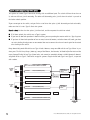
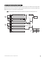
what is included
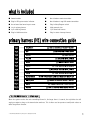
■ Control module
■
One 4-button remote transmitter
■ Plug-in LED system status indicator
■
One 5-button 2-way LCD remote transmitter
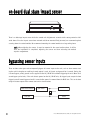
■ An on-board dual zone impact sensor
■
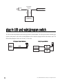
Plug-in Valet/Program switch
■ 12-pin primary harness
■
High-powered siren
■ 3-pin auxiliary harness
■
7-pin door lock harness
■ Plug-in 544N transceiver
■
Plug-in starter interrupt harness
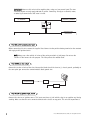
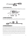
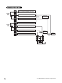
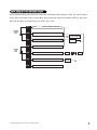
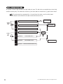
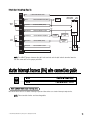
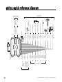
primary harness (H1) wire connection guide
H1/1
H1/2
H1/3
H1/4
H1/5
H1/6
H1/7
H1/8
H1/9
H1/10
H1/11
______
______
______
______
______
______
______
______
______
______
______
H1/12 ______
RED/WHITE
RED
(-) 200 mA CHANNEL 2 VALIDITY OUTPUT
(+)12V CONSTANT POWER INPUT
BROWN
(+) SIREN OUTPUT
YELLOW
(+) IGNITION INPUT, ZONE 5
BLACK
(-) CHASSIS GROUND INPUT
VIOLET
(+) DOOR TRIGGER INPUT, ZONE 3
BLUE
GREEN
BLACK/WHITE
WHITE/BLUE
WHITE
ORANGE
(-) MULTIPLEX TRIGGER INPUT, ZONE 1
(-) DOOR TRIGGER INPUT, ZONE 3
OUTPUT OF INTERIOR LIGHT ILLUMINATION RELAY #30
(-) 200 mA CHANNEL 3 VALIDITY OUTPUT
(+/-) SELECTABLE LIGHT FLASH OUTPUT
(-) 500 mA GROUND-WHEN-ARMED OUTPUT
H1/1 RED/WHITE channel 2, (-) 200mA output
When the system receives the code controlling Channel 2, for longer than 1.5 seconds, the red/white wire will
supply an output as long as the transmission continues. This is often used to operate a trunk/hatch release or
other relay-driven function.
© 2005 Directed Electronics, Vista, CA—all rights reserved
3