1
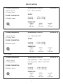
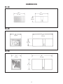
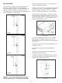
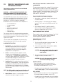
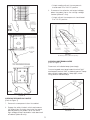
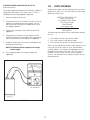
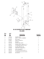
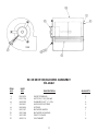
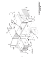
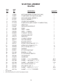
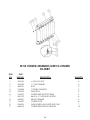
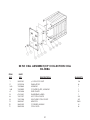
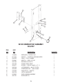
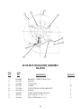
ELECTRONIC AIR CLEANERS
INSTALLATION AND OPERATION MANUAL
MODEL SE 30
MODEL SE 40
MODEL SE 50
SPECIFICATIONS
POWER REQUIREMENTS
AIR HANDLING CAPACITY
115 VAC, 60 HZ
3.2 Amps (max.)
Low - 150 to 420 CFM*
MODEL SE 30
WEIGHT
POWER CONSUMPTION
370 Watts (max.)
Hanging. . . . . . 75 lbs. (34 kg)
Shipping. . . . . . 82 lbs. (37 kg)
DIMENSIONS
Height
10 7/8"
(28 cm)
Width
20 1/4"
(51 cm)
Length
31"
(79 cm)
*CFM is variable
POWER REQUIREMENTS
AIR HANDLING CAPACITY
115 VAC, 60 HZ
6.0 Amps (max.)
Low - 450 to 950 CFM*
MODEL SE 40
WEIGHT
POWER CONSUMPTION
690 Watts (max.)
Hanging . . . . . 113 lbs. (51 kg)
Shipping. . . . . 120 lbs. (54 kg)
DIMENSIONS
Height
12 7/8"
(33 cm)
Width
21"
(53 cm)
Length
40"
(102 cm)
*CFM is variable
POWER REQUIREMENTS
AIR HANDLING CAPACITY
115 VAC, 60 HZ
7.0 Amps (max.)
High speed tap - 1,060 to 1,500 CFM*
Low speed tap - 590 to 1,300 CFM*
POWER CONSUMPTION
800 Watts (max.)
MODEL SE 50
WEIGHT
Hanging . . . . . 140 lbs. (63.5 kg)
Shipping . . . . . 151 lbs. (68.5 kg)
DIMENSIONS
Height
20"
(51 cm)
*CFM is variable
1
Width
19 1/2"
(50 cm)
Length
40"
(102 cm)
DIMENSIONS
SE 30
201⁄4"
51 cm
31"
79 cm
107⁄8"
28 cm
SE 40
21"
53 cm
40"
102 cm
127⁄8"
33 cm
SE 50
40"
102 cm
191⁄2"
50 cm
20"
51 cm
2
TABLE OF CONTENTS
SECTION
PAGE
I.
Introduction
4
II.
Inspection of Equipment
4
Ill.
How Your Air Cleaner Operates
4
IV.
Installation
4
V.
Operation
6
VI.
Cleaning
6
THE FOLLOWING INFORMATION IS PROVIDED
FOR TRAINED SERVICE PERSONNEL ONLY.
VII.
Periodic Maintenance and Troubleshooting
VIII.
Parts Ordering
10
Illustrated Parts
SE 30
SE 40
SE 50
Wiring Diagrams
12
18
24
30
IX.
IMPORTANT NOTICE
BEFORE OPERATION, PLEASE REMOVE ALL PACKING MATERIAL FROM INSIDE
UNIT. THIS CAN INCLUDE MARKED TIE DOWN SCREWS, CARDBOARD,
STYROFOAM AND PLASTIC WRAP ON CARBON FILTER. MODELS VARY IN
MATERIAL USED.
3
8
I.
INTRODUCTION
COMPONENTS THAT MAKE IT WORK
NOW YOU CAN BREATHE A LOT EASIER...
PREFILTER traps the larger particles and evenly distributes
the air across the ionizing section to maximize efficiency.
... you and everyone else who breathe the air cleaned
electronically by SMOKEETER®. Your new electronic air
cleaner is the most advanced product of its type on the
market today. As you begin its operation, we would like
to remind you of a few important facts.
IONIZER is made up of fine tungsten wires supported
between metal plates. When high voltage is applied to
these parts, a “corona” field is generated which imparts
a high-voltage charge on particles that pass through it.
First, we appreciate your business and because we
appreciate your business, we have manufactured an
electronic air cleaner worthy of your consideration.
SMOKEETER is designed and engineered to rigid
specifications incorporating the latest technological
advances. It is built using the highest grade materials
available. It is subjected to rigorous quality control
checks before it leaves our factory. And, the unit is
backed by a factory warranty as described on the back
cover.
COLLECTION CELL is made up of a series of convoluted
metal plates. These plates act like a magnet and attract
the charged particles removing them from the air. The
plates are alternately charged positive and ground. The
positive plates repel the particles while the ground plates
attract them, yielding a very high efficiency.
NOTE: The SE 40 contains an ionizer and collection cell as
a one piece assembly known as a unicell.
SPEED CONTROL SWITCH allows you to adjust the airflow
between 150 and 420 cubic feet of air per minute (CFM)
on the SE 30 and 450 and 950 CFM on the SE 40. The
switch on the SE 50 allows you to adjust the airflow
between 1,060 and 1,500 CFM on the high speed tap
and between 590 and 1,300 CFM on the low speed tap.
The SE 50 is shipped on high tap.
Second, like any piece of precision equipment, your
SMOKEETER unit needs periodic maintenance. Properly
cared for, it will operate at peak efficiency for many
years to come.
Finally, while we hope you never have any problems,
United Air Specialists, Inc. (UAS) is always ready to lend
assistance. We have factory-trained distributors
worldwide. Should you need information or service,
contact your local distributor or Customer Service at
United Air Specialists, Inc., 4440 Creek Road, Cincinnati,
Ohio 45242, 1-800-252-4647, www.uasinc.com.
II.
MOTOR/BLOWER produces air movement by a low
speed, dynamically-balanced, forward-curved blower.
The direct drive motor is thermally protected.
IV.
INSPECTION OF EQUIPMENT
NOTE: This product has been designed specifically for
commercial applications, such as offices, night
clubs, bowling centers and bingo halls. United Air
Specialists assumes no responsibility for those
applications unlike the aforementioned.
Upon receipt of your unit, check for any shipping
damage. A damaged carton indicates that the
equipment may have received rough handling during
shipping that may have caused internal damage.
Notify your delivery carrier and enter a claim
if any damage is found.
Ill.
INSTALLATION
HOW YOUR AIR CLEANER
OPERATES
The motor/blower assembly draws air through an
aluminum mesh filter which removes the larger particles in
the contaminated air. As the particles pass through the
ionizer section, they are given an intense positive charge.
These charged particles are then collected on cell plates.
The clean air is redistributed into the room by adjustable
outlet diffusers.
CAUTION: To reduce the risk of electric shock, this
equipment has a grounding-type plug that has
a third (grounding) pin. This plug will only fit
into a grounding-type power outlet. If the plug
does not fit into the outlet, contact qualified
personnel to install the proper outlet. Do not
alter the plug in any way.
SMOKEETER is designed to draw the contaminated air
through the unit and exhaust clean air back into the
room. The clean air is used to push contaminated air
around the room to the inlet of the unit. Directions of air
patterns and proper placement of the unit should be
established by your local SMOKEETER distributor or by
United Air Specialists, Inc.
The unit can be installed by mounting on a wall or
suspending from the ceiling joists/structure.
4
WALL MOUNTING
Remove the components from the unit to lighten the
weight and facilitate handling.
Level and securely attach the mounting cleat to the
wall, ensuring given dimension from ceiling to bolt
centerline as shown in Figure 1. Holes provided on wall
mounting cleat are spaced 12", 16" or 24" on center
mounting patterns. Use fasteners and anchoring devices
to ensure support of the SMOKEETER.
Attach the mounting cleat to the top back edge of the
unit with two 3/8-16 x 3/4” hex head bolts and washers
that are provided. Install two 3/8-16 x 11/4” leveling
screws in the bottom outside holes. Refer to Figure 2.
Place the unit on a lifting device. Position the lifting
device under the wall mounting cleat. Raise the unit
into position and engage the wall mounting cleat with
cleat mounted to the unit. Ensure engagement by
visually checking from the end.
SE 30
75 lbs.
SE 40
FIGURE 2
Check level and adjust leveling screws as needed.
Mark location on hold-down fastener on the wall.
Hole is located behind the collection cell and marked
with a label.
Remove the unit from mounting and prepare wall for
hold-down fastener.
Reinstall the unit as before and install hold-down
fastener.
The fasteners should now be tested to support the
weight previously mentioned.
113 lbs.
Completed installation should be as shown in Figure 3,
with mounting cleat fully engaged, leveling screw in
position and hold-down bolt in wall.
SE 50
138 lbs.
FIGURE 1
WARNING — ATTACH WALL MOUNT TO CLEAT TO WALL
AND TEST LOAD CAPACITY AS SHOWN IN ILLUSTRATION.
FIGURE 3
5
SUSPENSION
V.
Threaded rod, wire or eyebolts and chain may be used
for hanging the unit. Four “knockouts,” located as
shown in Figure 4, must be removed.
For best results and to assure maximum air quality, your
SMOKEETER unit should be started before the air
becomes contaminated. An indicator lamp indicates
that high voltage to the components is on. A variablespeed control switch allows you to adjust the blower
speed. If you notice a decrease of cleaning
efficiency, increase the blower speed to increase
effectiveness of the unit.
It is recommended that a nut on the inside and outside
of the cabinet be used to lock the fastener in place.
Refer to Figure 4.
OPERATION
Test the unit for secure support.
FOR YOUR INFORMATION — The equipment has been
thoroughly tested prior to shipment from the factory.
Even so, there may be some initial arcing of the
components at start-up. The noise should cease after
a few minutes of operation.
VI.
CLEANING
CAUTION: Servicing this product for purposes other than
routine cleaning of the collection
components should be performed by
trained authorized service personnel. Any
effort to exceed this service (by nonqualified personnel) may lead to bodily
injury and/or equipment failure.
SE 30
This section is defined for cleaning and periodic
maintenance. The internal components must be
removed prior to cleaning.
CAUTION: The unit should be inspected frequently and
dirt removed to prevent excessive
accumulation which may result in flashover
or fire damage. An electrical interlock is
provided for protection — do not defeat its
purpose.
HOW TO REMOVE COMPONENTS
1.
• Open the access door.
• For added safety, manually discharge the
ionizer and collection cell/unicell in the
following manner. Place the blade of a
common screwdriver (with insulated handle)
across the ionizer wire support and then the
ionizer frame. Next, place the screwdriver blade
across the cell end plate and then across a cell
“hot” plate. This will remove any residual
charge that may not have bled off. Refer to
Figure 5.
SE 40
2.
SE 50
FIGURE 4
Turn off the unit.
6
Slide components from the cabinet.
CLEANING
Major cleaning is confined to the prefilter, ionizer,
collection cell and the inside cabinet. These should be
cleaned periodically to assure continued efficiency.
Cleaning may be required from once a month to once
every four months depending on the air quality.
NOTE: The carbon filter cannot be cleaned and needs
to be replaced as required.
SE 30
SE 40
I.
Disconnect power to unit and remove
components.
2.
The ionizer, collection cell/unicell and prefilter
can be cleaned by soaking in a hot solution of
SMOKEETER brand detergent for 30 to 60 minutes.
If possible, agitate the solution to aid in dirt
removal. If agitation is not possible, soaking time
should be increased.
CAUTION: Do not use temperature exceeding 160°F
and do not steam clean as this may cause
permanent damage to the components. If
detergent other than SMOKEETER brand is
used, care must be taken to assure that it
contains an aluminum inhibitor so that it
does not attack the aluminum components.
Be sure to follow manufacturer’s cleaning
instructions.
NOTE: The SE 40 contains an ionizer and collection cell
as a one piece assembly known as a unicell.
FIGURE 5
7
3.
Remove the components from the detergent
bath and immediately flush away any residue and
rinse thoroughly with clear hot (less 160°F) water.
Shake off excess water and let components dry
for 30 to 60 minutes. Set the cell so that its plates
are in a vertical position for drainage.
4.
Vacuum clean the interior of the cabinet and
clean off all electrical connections before
reinstalling the components.
5.
Reinstall the components into the cabinet.
6.
Apply power to unit and confirm indicator light is
illuminated.
VIl.
HOW THE HIGH VOLTAGE IS SUPPLIED TO THE
COMPONENTS
PERIODIC MAINTENANCE AND
TROUBLESHOOTING
The power pack supplies high voltage DC to the ionizer
and collection cell by the use of high voltage lead
wires. Two separate terminals are used on the output
side of the pack. Terminal #8 supplies nominal 11,000
volts DC positive to the ionizer. Terminal #7 supplies
5,500 volts DC to the cell.
The following sections are for the use of trained
service personnel only.
WARNING — THE FOLLOWING PROCEDURES WILL
EXPOSE HAZARDOUS LIVE AND MOVING PARTS.
DISCONNECT AIR CLEANER BEFORE PROCEEDING.
TOOLS REQUIRED FOR TROUBLESHOOTING
All SMOKEETER air cleaners are manufactured to
give years of trouble-free performance. As with
any piece of equipment, however, breakdowns
can occur. Due to the simplicity of design,
breakdowns are restricted to these components:
•
•
•
•
•
•
•
the motor/blower*
the power pack
ionizer
collection cell/unicell
blower control switch
safety switch
indicator lamp
•
Screwdriver — (common type) 8” or longer with
insulated handle.
•
Volt-Ohm Meter — for measuring low voltage
input (115 VAC), continuity (OHMS) and low voltage DC.
•
High Voltage Probe (DC) positive polarity —
for checking the high voltage power supply
(minimum range from 0 to 15 KV DC).
HOW TO MEASURE HIGH VOLTAGE
This section covers the troubleshooting procedure
and a table which will enable you to determine the
cause of most problems. Refer to Section VIII for
replacement parts.
To accurately measure the high voltage, a 0 to 15 KV
minimum scale high voltage probe capable of
measuring positive polarity is required.
MEASURING HIGH VOLTAGE
(Refer to Figure 6)
*These models are equipped with permanently
lubricated motors. No further oiling is required.
1 . Turn the unit off and open the access door. This
will disengage the safety interlock.
COMPONENT FUNCTION
1. Power Pack - the electrical circuit is designed
around the power pack which contains the
necessary components to convert 115 Volts,
single-phase, 60 hertz to the high voltage DC
required for the components.
2. Connect the ground clip of the positive polarity
probe to the side of the cabinet.
CAUTION: Always ground the high-voltage probe
to a solid ground connection on the
metal cabinet.
2. Ionizer - the ionizing section supports several
tungsten wires charged positive to a nominal
11,000 volts DC. The baffle plates parallel to the
wire are at ground potential. The ionizer’s function
is to electrically charge the contaminated
particles as they pass through the ionizer.
3. Turn unit control switch on and cautiously
engage the safety interlock switch.
CAUTION: Be sure to disengage safety interlock
switch after measuring voltages.
3. Collection Cell - the collecting section consists of
alternately charged plates. Plates are alternately
charged with a nominal 5,500 volts DC positive.
The field between the plates forces the charged
particles to the ground plates removing them from
the airstream.
IONIZER VOLTAGE
Place the probe’s tip on the ionizer (refer to
Figure 6) and measure the positive DC voltage.
The voltage should read 10 to 11 KV DC.
• If measurements are abnormal, refer to the troubleshooting table (page 11) for cause and correction.
NOTE: The SE 40 contains an ionizer and collection cell
as a one piece assembly known as a unicell.
CELL VOLTAGE
Place the probe’s tip on one of the charged plates.
The voltage reading should be 4 to 6 KV DC.
4. Motor/Blower - draws in contaminated air and
exhausts clean air through the outlet.
• If measurements are abnormal, refer to the troubleshooting table (page 11) for cause and correction.
8
• Output reading without the components
should read 10 to 12 KV DC positive.
3. To measure the collection cell output voltage,
place the probe’s tip on the cell high voltage
contact (follow #7 wire).
• Output without the components should read
5 to 7 KV DC positive.
SE 30
SE 40
FIGURE 7
(Contact point locations may vary)
CHECKING LAMP TERMINAL OUTPUT
(Refer to Figure 8)
Disconnect unit indicator lamp (neon lamp).
Connect a good neon lamp to pack terminal “light”
and to pack terminal “GND” or cabinet ground. If lamp
does not light, replace pack. If lamp lights, check
wiring and unit indicator lamp.
SE 50
FIGURE 6
CHECKING THE POWER PACK OUTPUT
(Refer to Figure 7)
1. Remove the components from the cabinet.
2. Engage the safety interlock switch and measure
the output from the ionizer terminal of the power
pack by placing the probe’s tip on the ionizer
high voltage contact located on inside back wall
of cabinet (follow #8 wire).
FIGURE 8
9
CHECKING MOTOR CAPACITOR (SE 40 & SE 50)
(Refer to Figure 9)
VIII.
PARTS ORDERING
Replacement parts can be ordered from your local
distributor or from UAS. For information on your local
distributor, call or write:
The motor capacitor located on the side of the blower is
designed to start and run the motor when 115 VAC is
supplied (refer to wiring diagrams, page 30).
UNITED AIR SPECIALISTS, INC.
4440 CREEK ROAD
CINCINNATI, OHIO 45242
TEL. (513) 891-0400
1-800-252-4647
www.uasinc.com
1. Disconnect power to the unit.
2. Using a volt meter with a scale of 120 VAC minimum,
place the two leads of the meter across the two
connections at the top of the capacitor to ensure
no voltage is present.
ATTN: CUSTOMER SERVICE
DEPARTMENT
3. Remove the two brown wires from the top of the
capacitor.
The following information will be required for prompt
service:
4. Using a Volt-Ohm Meter with the scale on 10,000
(10K) OHM, place the two leads of the meter across
the two connections at the top of the capacitor.
1. Unit model number inside access door.
2. Unit serial number inside access door.
3. Part number of part (refer to Illustrated Parts).
5. Read the VOM scale. The meter should deflect to 0
and slowly rise to infinity.
When returning a defective part under warranty, you
must call UAS for a customer return authorization
number (RMA). This number should appear on the
package that is being returned. With this control
number, we can assure you will receive prompt
service. You can also return defective parts to your
local distributor.
NOTE: This indicates that the capacitor will charge
and discharge.
6. If the capacitor does not charge, replace the
capacitor.
FIGURE 9
10
TROUBLESHOOTING TABLE*
PROBLEM
POSSIBLE CAUSE
A.
Control switch on,
indicator lamp off,
blower operates.
1.
2.
3.
4.
B.
Control switch on,
indicator lamp on,
blower does not
operate.
1. Motor faulty.
2. Foreign object blocking
motor.
3. Faulty control switch.
4. Connector not properly
connected at control
switch.
1. Replace motor.
2. Clean foreign object from
motor.
3. Replace control switch.
4. Check connection at
control switch.
1. Loss of input 115 VAC.
2. Safety interlock switch
not engaged.
3. Safety interlock switch
defective.
4. Control switch defective.
1. Determine loss of input
voltage.
2. Engage safety interlock
switch.
3. Replace safety interlock
switch.
4. Replace control switch.
C. Control switch on,
motor and lamp off.
Defective lamp.
Faulty connection to lamp.
Loss of high voltage.
Loss of continuity of high
voltage.
CORRECTIVE ACTION
1.
2.
3.
4.
Replace lamp.
Check connection to lamp.
Check power pack.
Refer to Problem “E.” Follow
steps 1-4.
D.
Motor operates on
low or high speed
only.
1. Control switch defective.
1. Replace control switch.
E.
Poor air quality.
1. Ionizer/collection cell/
unicell dirty.
2. Ionizer/collection cell/
unicell malfunctioning.
1. Clean components.
3. Components installed
backwards or upside down.
4. High voltage contacts
dirty.
5. Unit being operated on too
low of a speed.
6. Placement of unit not
creating a good air
pattern.
F.
Loss of high voltage
output.
1. Loss of input 115 VAC.
2. Ionizer/collection cell/
unicell malfunctioning.
3. Power pack defective.
*Refer to wiring diagram and illustrated parts.
11
2. Check for:
A. Foreign matter
between plates.
B. Ionizer wire loose or
broken.
C. Defects in insulators.
3. Install components as
shown in Section IX.
4. Clean high voltage
contacts.
5. Increase blower speed.
6. Contact your local
distributor or United
Air Specialists.
1. Determine loss of input
voltage.
2. Check for:
A. Foreign matter
between plates.
B. Ionizer wire loose or
broken.
C. Defects in insulators.
3. Replace power pack.
IX.
SE 30 FINAL ASSEMBLY
02-2620
ILLUSTRATED PARTS
12
SE 30 FINAL ASSEMBLY
02-2620
*
+
ITEM
NO.
PART
NO.
1
2
3
4
6
7*
8A*
8B*
9*
10
11
12
13
14
15
16
18
20
22
25
26
29
31
32
33
34
35
36
37
42
45
47
48
49
50
02-0090
02-0522
20-2922
02-2608
02-2662
03-1076
30-0496
39-0120
10-2571
10-2711
10-2712
18-0763
20-0155
20-2921
21-1218
30-0015
30-0031
30-0038
30-0049
30-0163
30-0202
30-0030
33-0006
33-0017
33-0156
35-0191
36-0008
36-0016
37-0013
41-0674
41-1136
42-0156
42-0158
42-0176
42-0206
DESCRIPTION
IONIZER ASSEMBLY+
COLLECTION CELL+
CORD-IEC, 90 DEG.
CENTER POST ASSEMBLY+
MOTOR/BLOWER ASSEMBLY+
WIRE KIT (HIGH VOLTAGE)
LEVELER, FOOT
KNOB-SWITCH
HANGING BRACKET
MOTOR/BLOWER ACCESS DOOR
COMPONENT ACCESS DOOR
CABINET
BUSHING
IEC 30 POWER INLET
POWER PACK (GREY PLASTIC CONSTRUCTION)
SCREW, HEX HEAD
SCREW, OVAL HEAD
LOCKWASHER
WASHER-FLAT
CLIP (DOOR FASTENER)
FASTENER LOGO
LOCKNUT
FILTER-CARBON
FILTER- ALUMINUM MESH
DISCHARGE GRILLE
ACTUATOR ROD FOR SWITCH
HIGH-VOLTAGE CONTACT SPRING
GROUND SPRING
INSULATOR-CERAMIC
NAMEPLATE
LABEL, WIRING DIAGRAM
GASKET-NEOPRENE
GASKET-NEOPRENE
GASKET, 1/2” POLYESTER FOAM
GASKET - 1” X 1”
NOT SHOWN
SEE DETAIL PARTS LIST ON THE FOLLOWING PAGES
13
QUANTITY
1
1
1
1
1
1
2
1
2
1
1
1
2
1
1
1
2
1
2
1
2
2
1
1
1
1
2
2
2
1
1
1.5 ft.
0.9 ft.
2.7 ft.
0.9 ft.
SE 30 IONIZER ASSEMBLY
02-0090
ITEM
NO.
1
2
3
4
5
6
7
8
9
10
12
13
PART
NO.
DESCRIPTION
QUANTITY
10-0421
10-0367
10-0368
37-0004
36-0004
02-6274
10-0420
30-0030
35-0061
30-0315
30-0142
30-0081
END PLATE
CORNER CHANNEL
SUPPORT
INSULATOR, 1/2” X 21/2”
SPRING
WIRE-IONIZER W/LOOPED END 10M
PLATE
LOCKNUT, 1/4-20
ROD
RIVET, SEMI-TUBULAR
PAN HD. SCREW, #8-32 X 1/2” L
FLATWASHER, #8
2
2
2
4
8
4
3
4
2
8
8
4
14
SE 30 COLLECTION CELL ASSEMBLY
02-0522
ITEM
NO.
1
2
3
4
5
6
7
8
9
10
11
12*
PART
NO.
10-0348
10-0158
10-0157
35-0064
37-0008
35-0072
35-0067
30-0030
30-0316
30-0283
10-0779
10-0778
DESCRIPTION
END PLATE
CELL PLATE, HOT
CELL PLATE, GROUND
CORNER ANGLE
INSULATOR
ROD, THREADED
SPACER-PLAIN
LOCKNUT, 1/4-20
RIVET, SEMI-TUBULAR
WASHER, SPACER-CELL
CELL PLATE, GROUND NOTCHED
CELL PLATE, HOT NOTCHED
* NOT SHOWN
15
QUANTITY
2
10
10
4
8
8
124
16
16
8
5
6
SE 30 CENTER POST ASSEMBLY
02-2608
ITEM
NO.
1
2
3
4
5
6
7
8
9
10
11
12
14
15
PART
NO.
10-2708
02-1326
20-0229
20-0560
30-0164
30-0165
30-0301
30-0038
30-0345
37-0055
39-0105
30-0076
30-0036
30-0003
DESCRIPTION
CENTER POST
SPEED CONTROL ASSEMBLY
PILOT LIGHT
INTERLOCK SWITCH
RETAINER
SCREW, WING HEAD
SCREW, PAN HD, #6-32 X 11/4” L
LOCKWASHER, #6 INT TOOTH
DOUBLE SPEEDNUT, #6
LIMIT SWITCH INSULATION
LATCH, MAGNETIC
GROUND SCREW, #10-32 X 3/8”
LOCKWASHER, #10 EXT TOOTH
NUT, #10-32
16
QUANTITY
1
1
1
1
1
1
2
2
1
1
2
1
3
1
SE 30 MOTOR/BLOWER ASSEMBLY
02-2662
ITEM
NO.
3
4
6
7
8
9
10
11
12
PART
NO.
20-0323
22-0176
30-0049
30-0441
30-0443
32-0157
32-0158
32-0159
32-0013
DESCRIPTION
WIRE TERMINAL
MOTOR, 115/1/50-60
WASHER-FLAT, 1/4” DIA.
SHOULDER SCREW
SCREW
BLOWER WHEEL
BLOWER HOUSING
INLET FLANGE
GROMMET
17
QUANTITY
2
1
3
3
4
1
1
1
3
18
SE 40 FINAL ASSEMBLY
02-2724
SE 40 FINAL ASSEMBLY
02-2724
ITEM
NO.
1
2
3
4
5
6
7*
8*
9
10
11
12
13*
14
15
16
17
20
21
22
23
24
26
27
30
32
33
34
35
37
38
40
43
*
+
PART
NO.
10-2820
10-2821
02-2544
02-1321
02-2725
21-1218
03-1078
03-0667
33-0156
33-0054
33-0053
20-2922
10-2799
37-0013
36-0014
36-0077
10-2574
30-0031
30-0335
30-0206
30-0202
20-2921
20-0155
35-0191
30-0163
41-0674
42-0206
42-0156
42-0158
30-0119
30-0363
42-0149
42-0176
DESCRIPTION
MOTOR/BLOWER ACCESS DOOR (WG)
COMPONENT ACCESS DOOR (WG)
MOTOR/BLOWER ASSEMBLY +
UNICELL ASSEMBLY +
CENTER POST ASSEMBLY +
POWER PACK (GREY PLASTIC CONSTRUCTION)
WIRE KIT HV
INSTALLATIONS PARTS KIT
GRILLE
FILTER — MESH
FILTER — CARBON
CORD-IEC, 90 DEG.
HANGING BRACKET
INSULATOR
CONTACT SPRING
GROUND SPRING
BLOWER SUPPORT
SCREW OVAL HD #8-32 X 3/4” L
SCREW, HEX HD #8-32 X 3/8” L
SCR, FL HD #8-32 X 3/8” L
FASTENER
IEC 320 POWER INLET
BUSHING, 1/2” DIA.
ACTUATOR INTLK SWITCH
CLIP SOUTHCO
NAMEPLATE
GASKET — 1” X 1” POLYESTER
GASKET — NEOPRENE 1/16” X 3/8”
GASKET — NEOPRENE 1/8” X 1/2”
SCR, PAN HD. #8-32 X 5/16”
SCR, TEK #10-16 X 3/4”
GASKET — BUNA-N 3/16” X 11/2”
GASKET — 1/2” X 1” POLYESTER
NOT SHOWN
SEE DETAIL PARTS LIST ON THE FOLLOWING PAGES
19
QUANTITY
1
1
1
1
1
1
1
1
1
1
1
1
2
2
2
1
1
2
4
12
2
1
1
1
1
1
.83 ft.
2.6 ft.
1.0 ft.
2
3
.25 ft.
1.0 ft.
SE 40 UNICELL ASSEMBLY
02-1321
20
SE 40 UNICELL ASSEMBLY
02-1321
ITEM
NO.
PART
NO.
1
2
3
4
5
6
7
8
9
10
11
12
13
14
15
16
17
18
19
20
21
22
23
24
25
25A
26
27
35-0067
35-0175
10-1373
02-1318
10-1375
36-0004
03-0393
10-1374
37-0014
30-0142
30-0081
30-0520
30-0500
02-1318
35-0174
35-0194
30-0449
37-0008
10-1372
20-0155
10-0158
10-0157
10-1376
10-2283
03-0306
37-0042
10-1378
30-0030
DESCRIPTION
CELL SPACER
CELL ROD
AIR FOIL CORNER CHANNEL
CELL ROD TO CONTACT WIRE ASSEMBLY
IONIZER SUPPORT
IONIZER SPRING
IONIZER WIRE ASSEMBLY, SET OF 5
AIR FOIL CORNER CHANNEL
INSULATOR, IONIZER STAND OFF (1/2” DIA. 2”L)
#8-32 x 3/8” PAN HEAD SCREW
#8 FLAT WASHER
#10-32 x 1/2” HEX HEAD SCREW
#10-32 HEX NUT, LOCKING
IONIZER TO CONTACT WIRE ASSEMBLY
CELL HIGH-VOLTAGE CONTACT
IONIZER HIGH-VOLTAGE CONTACT
1
/4-20 HEX LOCK NUT
INSULATOR, CELL (DISC TYPE)
END PLATE
HOLE BUSHING
CELL PLATE (GROUND)
CELL PLATE (HOT)
IONIZER/CELL PLATE
CELL CORNER STRAP
CONTACT KIT, UNICELL HIGH-VOLTAGE
CELL HIGH-VOLTAGE CONTACT MOUNT PLATE
CELL CORNER ANGLE
1
/4-20 LOCKNUT (NYLON INSERT)
21
QUANTITY
156
8
1
1
2
10
1
1
4
8
4
4
4
1
1
1
1
8
2
1
15
20
4
1
1
1
1
15
SE 40 MOTOR/BLOWER ASSEMBLY
02-2544
ITEM
NO.
PART
NO.
1
2
3
4
5
6
32-0083
02-1327
20-0569
20-1298
30-0335
30-0077
DESCRIPTION
BLOWER — DIRECT DRIVE
MOTOR
CAPACITOR
CAPACITOR STRAP
SCREW — HEX HD #8-32 x 1/2” SELF TAP
SCREW — HEX HD 1/4” x 5/8” SELF TAP
22
QUANTITY
1
1
1
1
2
3
SE 40 CENTER POST ASSEMBLY
02-2725
ITEM
NO.
1
2
3
4
5
6
7
8
9
10
11
12
13
14
15
PART
NO.
10-2825
02-1326
20-0229
20-0560
30-0164
30-0165
30-0301
30-0038
30-0345
37-0055
39-0105
30-0076
02-2598
30-0036
39-0120
DESCRIPTION
EXTRUSION, CENTER POST
SWITCH — CONTROL VARIABLE SPEED
LIGHT — PILOT, AMBER
SWITCH — INTLK — DP NO
RETAINER, SOUTHCO
SCREW, WING HEAD
SCREW — PAN HD. #6-32 x 11/4” L
LOCKWASHER — #6 INT TOOTH
TINNERMAN NUT — #6, DOUBLE
INSULATION — SWITCH
LATCH, MAGNETIC
SCREW — #10-32 x 3/8” GROUND (GREEN)
WIRE HARNESS ASSEMBLY
LOCKWASHER — #10 EXT. TOOTH
SPEED CONTROL KNOB
23
QUANTITY
1
1
1
1
1
1
2
2
1
1
2
1
1
3
1
24
SE 50 FINAL ASSEMBLY
02-2726
SE 50 FINAL ASSEMBLY
02-2726
ITEM
NO.
1
2
3
4
5
6
7
8
9
10
11
12
13
14
15
16
17
18
19
20
21
22
23
24
26
27
28
29
30
32
33
35*
39*
40
41
43
44
45
47
48*
49*
*
+
PART
NO.
18-0800
10-2823
10-2822
02-2576
02-2727
33-0039
21-1218
33-0001
02-0089
02-0086
33-0007
10-2606
10-2799
20-2922
20-2921
36-0077
37-0013 or
37-0063
36-0008
30-0119
35-0191
30-0015
30-0038
30-0030
30-0036
30-0206
30-0031
30-0502
41-0674
42-0206
42-0156
42-0158
03-0030
30-0076
30-0063
42-0149
30-0163
30-0049
30-0363
42-0063
30-0363
36-0016
DESCRIPTION
CABINET WELDMENT
COMPONENT ACCESS DOOR
BLOWER ACCESS DOOR
MOTOR/BLOWER ASSEMBLY +
CENTER POST ASSEMBLY +
DISCHARGE GRILLE
POWER PACK (GREY PLASTIC CONSTRUCTION)
MESH FILTER
IONIZER ASSEMBLY +
COLLECTION CELL +
CARBON FILTER
BLOWER SUPPORT ANGLE
HANGING BRACKET
CORD-IEC, 90 DEG.
IEC 320 POWER INLET
SPRING GROUND
INSULATOR
INSULATOR
CONTACT SPRING
SCR, PAN HD 8-32 X 5/16” THD-CUT
ACTUATOR INTLK SWITCH
SCR-HEX HD SLOTTED #6-32 X 3/8”
LOCKWASHER #6 INT TOOTH
NUT HEX 10-32
LOCKWASHER #10 EXT TOOTH
SCR, FLT HD SELF-TAP 8-32 X 3/8”
SCR, OVAL HD #8 X 3/4” LG #6 HD
SCR, PAN HD #8-32 X 5/16” THD CUT
NAMEPLATE
GASKET — 1” X 1” POLYESTER FOAM
GASKET — NEOPRENE 1/16” X 3/8”
GASKET — NEOPRENE 1/8” X 1/2”
HV LEAD ASSEMBLY
SCR, HEX HD (GREEN) 10-32 X 3/8”
BOLT, HEX HD THD-CUT 1/4-20 X 5/8”
GASKET — BUNA-N 3/16” x 11/2”
CLIP
WASHER, FLAT FOR #10 SCR
SCR, TEK 10-16 X 3/4” WISEAL WASHER
GASKET — EDGE
GROUND SPRING FAST
GROUND SPRING
NOT SHOWN
SEE DETAIL PARTS LIST ON THE FOLLOWING PAGES
25
QUANTITY
1
1
1
1
1
1
1
1
1
1
1
1
2
1
1
2
1
1
2
2
1
1
1
2
5
14
4
2
1
1.5 ft.
2.4 ft.
1.6 ft.
1
3
1
.125 ft.
1
2
7
.08 ft.
2
2
SE 50 IONIZER ASSEMBLY/AIRFOIL IONIZER
02-0089
ITEM
NO.
1
2
3
4
5
6
7
8
9
10
11
PART
PART NO.
30-0030
30-0049
35-0027
10-0465
37-0004
10-0570
30-0142
30-0081
10-0420
02-6274
36-0004
DESCRIPTION
QUANTITY
/4-20 LOCK NUT
/4” FLAT WASHER
ROD
CORNER CHANNEL
INSULATOR
IONIZER WIRE SUPPORT RAILS
#8-32 X 1/2” PAN HEAD SCREW
#8 FLAT WASHER
IONIZER PLATE
WIRE-IONIZER W/LOOPED END 10M
IONIZER WIRE SUPPORT SPRING
4
4
2
2
4
2
8
4
6
7
14
1
1
26
SE 50 CELL ASSEMBLY/CP COLLECTION CELL
02-0086
ITEM
NO.
PART
NO.
1
2
3-A
3-B
4
5
6
8
9
10
11
30-0030
37-0008
10-0564
10-0559
10-0348
41-0330
10-0157
10-0158
35-0067
35-0049
35-0045
DESCRIPTION
1
/4-20 LOCK NUT
INSULATOR
HANDLE
COVER PLATE, HANDLE
END PLATE
WARNING LABEL
HOT CELL PLATE
GROUND CELL PLATE
SPACER
CORNER ANGLE
CELL ROD
27
QUANTITY
16
8
1
1
2
1
33
32
260
4
8
SE 50 CENTER/POST ASSEMBLY
02-2727
ITEM
NO.
1
2
3
4
5
6
7
8
9
10
11
12
13
PART
NO.
10-2826
02-1326
20-0229
20-0560
30-0164
30-0165
30-0301
30-0038
30-0345
37-0055
39-0105
02-2542
39-0120
DESCRIPTION
EXTRUSION, CENTER POST
SWITCH — CONTROL VARIABLE SPEED
LIGHT — PILOT, AMBER
SWITCH — INTLK - DP NO
RETAINER, SOUTHCO
SCREW, WING HEAD
SCREW — PAN HD. #6-32 x 11/4” L
LOCKWASHER — #6 INT. TOOTH
TINNERMAN NUT — #6, DOUBLE
INSULATION — SWITCH
LATCH, MAGNETIC
WIRE HARNESS ASSEMBLY
KNOB-SWITCH
28
QUANTITY
1
1
1
1
1
1
2
2
1
1
2
1
1
SE 50 MOTOR/BLOWER ASSEMBLY
02-2576
ITEM
NO.
PART
NO.
1
2
3
4
5
6
7
8
9
32-0085
02-1357
20-0569
42-0153
20-1298
20-0138
20-0290
30-0233
30-0335
DESCRIPTION
BLOWER — DIRECT DRIVE 10-10
MOTOR
CAPACITOR
GASKET
CAPACITOR MOUNTING BRACKET
WIRE TIE
CABLE TIE MOUNTING DEVICE
BOLT, HEX HD 1/4 -20 x 1” L
DRILL SCREW #8-32 x 1/2” L
29
QUANTITY
1
1
1
1 ft.
1
2
2
3
2
WIRING DIAGRAM
MODEL SE 30
41-2487
WIRING DIAGRAM
MODEL SE 40
MODEL SE 50
41-2488
30
UNITED AIR SPECIALISTS, INC,
LIMITED WARRANTY
UAS warrants all equipment manufactured and sold by UAS against defective parts and
workmanship for one year from date of shipment to Purchaser, except that commercial or
nonindustrial air cleaners (other than engineered systems) are warranted for three years
from such date. This warranty is subject to the limitations in UAS’ standard terms and
conditions provided to Purchaser. Any unauthorized repairs or modifications or abnormal
use or misuse of equipment will void all warranties. In no case will UAS’ responsibility or
warranty extend to equipment not manufactured by UAS.
THE FOREGOING WARRANTY IS EXCLUSIVE AND IN LIEU OF ALL OTHER WARRANTIES, WHETHER
WRITTEN, ORAL OR IMPLIED, INCLUDING ANY IMPLIED WARRANTY OF MERCHANTABILITY,
FITNESS FOR A PARTICULAR PURPOSE OR NONINFRINGEMENT.
As Purchaser’s exclusive remedy for any defects in the equipment, UAS will exchange or
repair any defective parts during the warranty period, provided such parts are returned,
prepaid, to UAS’ factory. The obligation of UAS is limited to furnishing replacement parts
F.O.B. UAS’ factory or making repairs at UAS’ factory of any parts which are determined,
upon inspection by UAS, to be defective. UAS is not responsible for labor or transportation
charges for the removal, reshipment or reinstallation of the parts.
IN NO EVENT WILL UAS BE RESPONSIBLE FOR ANY SPECIAL OR CONSEQUENTIAL DAMAGES.
4440 Creek Road • Cincinnati, Ohio 45242 USA
National Phone: (800) 252-4647
Telephone: (513) 891-0400 • Fax: (513) 891-4882
http://www.uasinc.com
An ISO 9001 Certified Company
© 1998, 2000 United Air Specialists, Inc.
PART NO. 44-2553
6/00
United Air Specialists, Inc. reserves the right to
change design or specifications without notice.