1
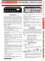
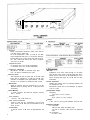
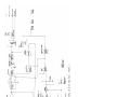
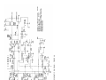
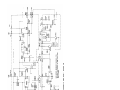
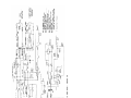
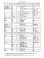
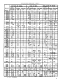
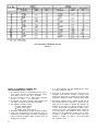
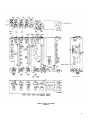
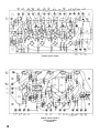
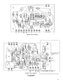
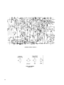
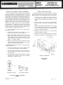
MODELS SE30 & SE30-2E
GATED COMPRESSOR/MIXER
OPERATING AND SERVICE MANUAL
Copyright 1981, Shure Brothers Inc.
27A8025 (AK) (90A8103)
Printed in U.S.A.
Table of Contents
List of Illustrations
WARNING
To reduce the risk of fire or electric shock, do not
expose this appliance to rain or extreme moisture.
(Model SE30 shown)
DESCRIPTION
The Shure Model SE30* Gated Compressor/Mixer is a
high-quality gated memory compressor combined with a
self-contained, portable, three-input mixer and remote
amplifier designed specifically for professional applications in AM, FM, and TV broadcasting, film, tape, and
disc recording, CATV, and sound reinforcement. An accessory cover is available (A100A) which covers the front
controls and provides a handle, as well as a support stand
for tilting the front panel upward for easier vision of controls during operation. An accessory rack-mount kit
(A100B) is available for permanently installed program
compressor applications.
Features include:
Three transformer coupled inputs, switchable, low impedance microphone or line level.
Individual feedback-type level controls for each input
to provide maximum clipping and minimum noise levels
over a wide dynamic range.
Low-frequency roll-off switch for each input.
Input 1 switchable on front panel to low-distortion, 1 kHz
tone oscillator.
Mix bus jack for adding additional mixers for additional
input capability.
Feedback-type output control (located after compression attenuator) to provide optimum output noise level
regardless of setting.
Binding posts for balanced 600-ohm line output plus
professional three-pin male audio connector switchable
from line to microphone level output.
Two-level headphone monitor jack for 600 to 2,000 ohm
headphones.
Compression range of 40 dB, with a slope or compression ratio of approximately 10 to 1 in the normal operating range.
Gated Memory with a meter indicator to minimize
“pumping.”
True average-responding compression to maximize
output level regardless of peak-to-average ratio of program material, either music or speech. (Peak responding
circuit to reduce gain rapidly for significant increases in
the input signal.)
Response rate (averaging time constant) adjustment on
front panel to compensate for various types of program
material.
Extremely low distortion, noise, and RF susceptibility,
with wide, flat frequency response at any level of compression.
+18 dB output capability.
Dual-scale illuminated meter for output VU indication
or dB compression.
+4 or +6 dBm range switch for VU meter.
AC or battery operation with built-in battery supply using
readily available 9-volt batteries.
*Unless otherwise noted, information applies to both SE30 and SE30-2E models.
Automatic, noiseless switch-over to batteries in the
event of ac line failure.
Battery-check switch to check battery condition without interrupting operation of unit.
Detachable ac line cord.
Auxiliary meter lamp operates independently from a “D”
type dry cell for meter illumination when ac power is
not available.
Auxiliary high level input and output on phone jacks for
special applications (approximately --20 dBV).
Microphone and line inputs and outputs phase indicated.
Stereo parallel jack for synchronizing the compression
circuits of two units.
Listed by Underwriters’ Laboratories and Canadian
Standards Association (SE30 only).
GUARANTEE
This Shure product is guaranteed in normal use to be
free from electrical and mechanical defects for a period
of one year from date of purchase. Please retain proof of
purchase date. This guarantee includes all parts and
labor. This guarantee is in lieu of any and all other guarantees or warranties, express or implied, and there shall
be no recovery for any consequential or incidental
damages.
SHIPPING INSTRUCTIONS
Carefully repack the unit and return it prepaid to:
Shure Brothers Incorporated
Attention: Service Department
1501 West Shure Drive
Arlington Heights, Illinois 60004
If outside the United States, return the unit to your dealer
or Authorized Shure Service Center for repair. The unit
will be returned to you prepaid.
SPECIFICATIONS
Frequency Response:
Flat ±2 dB, 30 to 20,000 Hz.
Gain:
(Below compression threshold, output terminated,
Line 600 ohms, Microphone 150 ohms, Aux. 47 K
ohms.)
Noise:
Equivalent input noise: -129.5 dBV maximum (Microphone input, 150 ohms, 20 kHz equivalent noise bandwidth with lower cutoff frequency of 300 Hz, at full
gain.)
Equivalent input hum and noise: -126 dBV maximum
(same as above, but lower cutoff frequency of 20 Hz.)
Output: (Input controls minimum):
3
SPECIFICATIONS (Cont’d)
Input/Output:
Distortion:
Below compression threshold, under 0.5% THD at
+15 dBm output, 30-20 kHz.
At 10 dB compression, under 1% THD at +15 dBm
output, Response Rate set to 7, 50-20 kHz. With Response Rate set to 0 (fast), under 2% THD at 50 Hz.
At 1 kHz, under 0.8% THD at any level of compression from 0 to 40 dB.
Compression Ratio:
8:1 minimum from 10 to 20 db compression.
5:1 minimum from 10 to 30 dB compression.
Compression Threshold:
Microphone: -96 dBV at maximum input gain.
Line: -48 dBV at maximum input gain.
Recovery Time:
Time required for gain to reach 90% of its final value
when input is reduced by 10 dB from 20 dB compression is adjustable from approximately 100 milliseconds to 8 seconds by Response Rate control.
Attack Time:
Same as recovery time for increases up to 12 dB.
Maintains peak to average ratio at 12 dB (sine-wave
equivalent).
Gated Memory:
In “hold” condition, less than 20 dB gain recovery
after 1 minute.
Tone Oscillator:
1.0 kHz ± 10%, THD under 1%.
Input Control Interaction:
Under 0.1 dB with any combination, mix bus jack
open. Under 1.5 dB with mix bus terminated in 50 K
ohms or less.
Lo-cut Filters:
-6 dB per octave, 3 dB down at approximately 150
Hz.
4
Mix bus:
Impedance 3.9 K ohms. Gain (through 3.9 K ohms)
from mix bus to line output, is 63 dB. Gain from microphone input to mix bus is 26 dB (terminated in 3.9 K
ohms). Overall gain drops by 10 dB with mix bus
terminated.
Circuit Protection:
Shorting the outputs, even for prolonged periods, will
not damage the unit.
Microphone inputs will not be damaged by signals
of up to 3 volts.
Temperature Range:
Operating:
-18°C (0°F) to 57°C (135°F).
Storage:
-29°C (-20°F) to 74°C (165°F).
Weight:
9 Ibs., 13½ oz. (4.5 kg) with batteries and line cord.
Operating Voltage:
AC Operation:
108-132 volts, 50/60 Hz (SE30 only).
108-132 or 216-264 volts, 50/60 Hz (SE30-2E
only).
DC Operation:
30 volts ± 20%.
SPECIFICATIONS (Cont’d)
Battery Operation:
27 volts nominal, 21.5 volts minimum. Current consumption at 27 volts, 10 ma. at no signal; 12 ma. at
20 dB compression and +8 dBm output.
Battery Life:
Estimated 80 hours at 4 hours use per day.
Battery Complement:
9 volt, 6 Eveready type 222 or 216 or equivalent.
One heavy-duty 1.5 volt “D” size cell, Eveready type
D99 or equivalent to power Aux. Light approximately
8 hours continuously.
CONTROL AND CONNECTOR
DESCRIPTIONS (See Figure 2)
(1) Input Controls: Control gain of individual input stages
to adjust relative levels between inputs and to adjust
amount of compression. Input 1 (1A) also controls
Tone Oscillator level when used.
(2) Lo-cut Filter Switches: Low frequency response is reduced by 6 dB per octave below approximately 150 Hz
with switch set to IN. Input 1 switch (2A) also activates
tone oscillator.
(3) Output Control: Controls output level when unit is
used in compression or acts as a master gain control
when compression is disabled. May be used for overall fading. Does not affect amount of compression.
(4) VU Range Switch: Selects meter sensitivity so 0 VU
indicates results from either +4 dBm or +8 dBm line
output level.
(5) Gated Memory Indicator: Will be red when Gated
Memory is “holding” prior amount of compression
during a low input signal. Will be white whenever input signal is above compression threshold, or if either
Gated Memory or compression is disabled. Illuminated by ac operated lamps or independent battery
operated auxiliary light.
(6) Response Rate Control: Adjusts time constant of
compression system to compensate for different types
of program material. Generally, a faster setting (lower
numbers) results in a more constant output level but
a more audible compression effect. Setting this control is a subjective matter, but the following guidelines may be used:
(7) Meter: Indicates either VU output level (upper VU
scale) or compression due to input signal above threshold by the amount indicated (lower DB Compression
scale). VU meter isolated from dc on line output. Illuminated by ac operated lamps or independent battery operated auxiliary light.
(8) Meter Switch: Selects function of meter for VU output level or DB Compression.
(9) Battery Check Switch: Spring-return switch overrides
Meter switch, allows checking battery condition without affecting operation of unit. A reading of 0 VU indicates end-of-life.
(10) Aux. Light Switch: Spring-return switch allows illumination of meter and Gated Memory indicator from
internal battery.
(11) Power Switch: Controls ac, external dc and internal
battery power applied to the unit, but will not prevent
power from being drawn from the internal batteries by
a load connected to 30 Volts DC jacks (26) when
switched to OFF.
REAR PANEL
Mix Bus Jack: Phono pin jack allows adding inputs by
interconnecting to a similar jack on another SE30
or M67 Mixer.
(13) Input Connectors: Female professional three-pin audio connectors* accept balanced low-impedance microphone or high-level line inputs. Wired with pins
2 and 3 “hot” and pin 1 ground.
(14) Mic/Line Input Switches: Select either microphone
or line level input sensitivity for each input.
(15) Aux. Line Input Jack: Three-conductor (tip, ring,
sleeve) phone jack provides a second balanced line
input for Input 1. May be used in conjunction with, or
instead of, three-pin input connector when input
switch (14A) is set to LINE. Inserting a two-conductor
phone plug will automatically unbalance the input
without otherwise affecting operation. Tip and ring
are “hot,” sleeve is ground, and tip is in phase with
pin 2 of input and output.
(16) Output Connector: Male professional three-pin audio
connector* provides balanced output at either line
level or microphone level (50 dB below line level).
Wired with pins 2 and 3 “hot” and pin 1 ground, in
phase with input connectors.
(17) Mic/Line Output Switch: Selects either microphone
or line level output at output connector.
Aux.
Output: Two-conductor (tip-sleeve) phone jack
(18)
provides isolated unbalanced aux. level (20 dB below
line level) output, for use with tape and cassette recorders and power amplifiers with high level, high
impedance inputs. Tip of jack is in phase with tip of
Aux. Line Input jack (15).
(19) Headphone Jack: Three-conductor (tip, ring, sleeve)
phone jack wired to provide two different output levels
for 600 to 2,000 ohm headphones. If a two-conductor
(tip, sleeve) phone jack is inserted partially (to the first
detent), output will be approximately .18 volts into
1,000 ohms at +4 dBm output. If the plug is inserted
fully, the voltage will be approximately .38 volts. If
stereo headphones are used, signal will appear in both
phones. The tip and ring are in phase with pin 3 of
the input and output.
(20) Line Output Terminals: Thumbscrews for direct wire
connections to balanced line, wired in parallel with
three-pin Output connector (16) in LINE position of
switch only. Phase is indicated by pin number references, and a ground thumbscrew is provided.
(21) Gated Memory Switch: Will disable Gated Memory
function without affecting other operation.
(22) Compression Switch: Will disable compression and
Gated Memory functions of the SE30, converting it to
a high-quality linear mixer and remote amplifier.
(23) Stereo Parallel Jack: Phono pin jack allows two units
to be synchronized to compress equally the channel
sum (L + R) signal. See Service section.
(24) Battery Compartment: Requires six readily available
O-volt batteries (Eveready type 222 or 216 or equivalent) wired in series-parallel for 27 volts dc and one
heavy-duty D cell (Eveready type D99 or equivalent)
*Designed to mate with Cannon XL series, Switchcraft A3 (Q. G.) series. or equivalent connector.
5
CONTROLS AND CONNECTORS
FIGURE 2
(25) AC Power Receptacle: Special internationally accepted connector for detachable ac line cord, threewire with safety ground pin.
(26) 30 Volts DC Jacks: May be used for powering the
unit from an external 30 ± 20% dc source, or for
powering external equipment (up to 5 ma) from the
batteries or ac operated power supply of the SE30.
Controlled by front-panel Power switch (11) except
that an external load will discharge the batteries with
the unit OFF. In this case, remove the Battery Compartment (24) when unit is turned off.
(27) Voltage Selector Switch: Selects operating voltage
range of 108-132 V or 216-264 V (SE30-2E only).
GENERAL OPERATION
(See Figure 2)
POWER CONNECTIONS:
AC Line Operation: Insert female end of ac line cord into
chassis power receptacle (25) and connect male plug to a
three-wire grounding ac power receptacle providing 108
to 132 V, 50/60 Hz (SE30 only). Model SE30-2E: Obtain
a suitable three-pin male plug and attach it to the line
cord. Plug should be installed by qualified service personnel. (Brown lead goes to “hot” or “live” terminal, blue
lead to neutral terminal, and green/yellow lead to ground
or earth terminal.) Select the proper operating voltage
(108-132 V or 216-264 V) using the voltage selector switch
(27). Insert female end of line cord into chassis power receptacle (25) and connect male plug to a three-wire
grounding ac power receptacle providing the proper operating voltage (108-132 V or 216-264 V, 50/60 Hz).
Battery Operation: Unit will automatically operate on batteries installed in Battery Compartment (24) if unit is not
supplied with ac power. Condition of the 9-volt batteries
should be checked periodically with the Batt. Check Switch
(9) and batteries should be replaced as the meter indication approaches 0 VU with the unit in operation. Standby
battery condition may be checked even during ac line
operation, but an indication of +½ VU should be considered as the replacement point, since the battery voltage
will drop somewhat under load. The auxiliary light D cell
may be checked by operating the Aux. Light switch (10).
If the light becomes extremely dim, promptly replace or
remove the D cell to avoid damage due to leakage.
The unit will remain operative, except for the light, regardless of the condition of this cell.
Automatic Switchover: If batteries are installed in Battery
Compartment (24). operating power will be supplied by
these batteries in the event that the ac line voltage drops
too low or is removed. The switchover is automatic and
noiseless.
External DC Operation: An external source of dc may be
connected to the 30 Volts DC jacks (26) to operate the
unit if ac power is not used. The SE30 will draw approximately 12 ma. at 30 volts and must be operated at 30 volts
± 20%.
INPUT CONNECTIONS:
Microphones: Inputs (13) with switches (14) set to MIC.
are designed to accept signals from low impedance (25 to
600 ohms) dynamic, ribbon, or condenser microphones,
or microphone level signals such as the low impedance
microphone level output of a mixer. Inputs are balanced
(transformer coupled, mumetal shielded) and connections
are pins 2 and 3 “hot,” pin 1 ground. For unbalanced
sources, connect either pin 2 or pin 3 to ground at the
input cable connector.
High Level Signals: With switches (14) set to LINE the
inputs (13) will accept balanced 600-ohm line signals.
Inputs are bridging (with 66 K ohm impedance) so that
higher impedance sources such as Aux. signals (up to
33 K ohms) may also be used. For such unbalanced inputs, the signal may be applied to pin 3, with pins 1 and
2 ground. Input 1 can accept two high-level signals simultaneously through the three-pin Input connector (13a), and
through the Aux. Line Input jack (15), which are electrically
isolated but identical in gain and impedance.
OUTPUT CONNECTIONS:
Microphone: The microphone level output is available at
the Output connector (16) when the switch (17) set to MIC.
It is used for feeding a low-impedance microphone line
or the low impedance microphone input of an associated
piece of equipment. This is a balanced output with pin 1
ground and pins 2 and 3 “hot” and in phase with the corresponding input pins. This output is isolated and may be
used simultaneously with all other outputs appearing on
other connectors.
Line: The line output is available at the Output connector
(16) when the switch (17) is set to LINE, and at all times
at the Line Output terminals (20). These two connectors
are then wired in parallel and are provided for interconnection convenience for either standard three-pin audio
connectors or for wires such as a telephone twisted pair.
This is a balanced output, transformer coupled with pin 1
ground and pins 2 and 3 “hot” and in phase with the corresponding input pins. The Line Output terminals (20) are
similarly numbered for phase indication. This output may
be used to drive impedances above 150 ohms but the VU
meter is properly calibrated for use with a 600-ohm terminated line. The line output transformer will operate properly with up to 100 ma. flowing through the line, permitting
the use of ordinary “dialed-up” telephone lines with dc
across them. Operation at +4 dBm output is recommended
for this use to avoid any significant increase in distortion
due to overdriving the phone line. This output is isolated
and may be used simultaneously with all other outputs except that the Output connector (16) and Line Output terminals (20) are wired in parallel when the switch (17) is set to
LINE.
Aux. Output: An unbalanced output 20 dB below line level
is available at the Aux. Output jack (18) for a Separate,
isolated lower level feed. The impedance is 4.3 K ohms,
suitable for driving high impedance (10 K ohms or greater)
loads, such as reel to reel or cassette tape recorders or
power amplifiers. Tip of jack is in phase with tip of Aux.
Line Input jack (15).
Headphones: The headphone output appears on the rear
panel and is designated “Headphones.” A three-conductor
phone jack is used to provide a choice of level for different
sensitivity or impedance headphones. Normally, a two-conductor phone plug should be used. If inserted only partially (to the first detent), the available voltage is approximately .18 volts into 1,000 ohms with +4 dBm out of the
Line Output. With the same output conditions (+4 dBm),
the second position will provide approximately .38 volts.
These voltages are selected for normal operation with
600-ohm to 2,000-ohm headphones. Other headphone impedances may be used, but with a variation in the headphone monitor level. The headphone jack is isolated from
the line output and with the headphone output shorted the
maximum change in line level output is .5 dB. If stereo
phones are used, the three-conductor plug may be inserted
completely (to second position) and output will appear in
both phones.
7
GENERAL OPERATION (Cont’d)
The “Tip” connection of the headphone plug will be in
phase with Pin 3 of all Input (13) and Output (16) connectors, and with the tip of the Mix Bus jack (12).
TYPICAL SET-UP AND OPERATION
A typical set-up and operation procedure is described
for remote amplifier applications, with a single input source
(microphone).
1. Connect microphone to Input 1 connector (13a) and
set Input switches (14) to MIC. Set Output Switch (17)
to LINE and connect phone line either to Output jack
(16) or Line Output terminals (20). Insert ac line cord
into ac receptacle (25) and plug cord into ac source,
unless battery operation is desired. Monitor headphones may be connected to Headphone jack (19).
2. Set Compressor (22) and Gated Memory (21) switches
to ON, Meter switch (8) to DB COMP, Lo-Cut switches
(2) and VU Range switch (4) as appropriate.
3. Rotate Input Control (1) and Output Control (3) full
counterclockwise to 0, and set Response Rate Control
(6) to 3, assuming a typical speech input.
4. Turn Power switch (11) ON and wait approximately 1
minute for the circuitry to stabilize. DB Comp. meter (7)
should read full scale left (line below zero on lower
scale) and Gated Memory indicator (5) should be red.
5. Set Input 1 switch (2a) to TONE OSC. and rotate Input
1 Control (la) clockwise for a DB Compression meter
(7) reading of 10 (lower scale). Gated Memory indicator (5) will change to white.
6. Set Meter switch (8) to VU and rotate Output Control
(3) for a VU meter (7) reading of 0 VU (upper scale).
Tone will be heard in headphones. The signal thus applied to the line may be used for calibration of the
equipment receiving the signal.
7. Reduce setting of the Output control (3) for a meter
reading of -2 VU, and return Input 1 switch (2a) to
IN. Note setting of Output Control (3) for future use.
(This reduction in sine-wave output is made to account
for the moderate short-term output dynamic range encountered for speech with the suggested Response
Rate control setting. A faster setting would eliminate
the need for this, but the compression would then become more audible.)
8. Set Meter switch (8) to DB COMP.
9. Now, with the expected average sound level entering
the microphone, set the Input 1 control (la) for an
average DB Compression meter (7) reading of approximately 10 (lower scale). This is the recommended
operating level for the SE30, since the unit will now
be able to maintain a substantially constant output
level for input reductions of 10 dB and increases of
as much as 30 dB.
10. Observe the operation of the Gated Memory indicator
(5). It should be white during speech input and change
to red during pauses between sentences and words,
indicating that the DB compression level is being
“remembered” during program lapses.
If the indicator remains white or “jitters” with no
spoken input to the microphone, it is an indication
that the acoustic background noise level at the microphone is near or above the Gated Memory threshold.
The solution to this is to reduce the setting of the
Input 1 Control (1a) until the Gated Memory Indicator
(5) is consistently red without speaking into the microphone. The DB Compression level will then be determined by the loudness of the speaker and his proximity
8
to the microphone. This adjustment is very important
to insure proper operation in situations having very
high background noise levels, such as sporting events
or parades.
OPERATING CONSIDERATIONS
LARGE CHANGES IN INPUT LEVEL
If the overall sound and noise levels entering the microphone do not significantly change from those encountered
during set-up, as indicated by a DB Compression meter
(7) reading of 0 to 20 dB, and if proper operation of the
Gated Memory indicator (15) continues, it will not be necessary to adjust any controls further.
If, however, large changes in the signal going into the
microphone and/or in background noise do occur, some
Input 1 control (1A) readjustment may be advisable, as
indicated by the DB Compression meter and Gated Memory indicator. For example, a significant increase in background noise and signal may occur during an exciting portion of a sporting event, such that the Gated Memory no
longer “holds” during pauses and the DB Compression
reads higher than previously indicated. A gradual reduction of the Input 1 control (1a) setting will not be noticeable
to the listener, due to the automatic effect of the compressor, but proper action will be restored.
During a later, more subdued portion of the program, it
may become apparent that the DB Compression meter (7)
is reading near zero, and the Gated Memory indicator does
not always change to white during speaking. A gradual
increase of the Input 1 control (la) setting will then allow
operation at the proper level. Thus, during operation, after
setting the proper output level with the master gain control,
it is generally necessary only to monitor compression level
on the DB Compression meter (7) and to observe proper
action of the Gated Memory indicator (5).
Control setting changes need only be made for longterm, large changes in signal or noise levels. It is not necessary to “ride gain” to maintain a constant line output
level as measured by the VU meter, since that is the compressor’s function.
RESPONSE RATE ADJUSTMENT
The proper setting of the Response Rate control (6)
is determined by subjective factors, according to the type
of program material. Generally, a slower setting will result
in less audible compression, but a wider short-term output dynamic range, that is, a less consistent output level.
Faster settings will result in a more nearly constant output
level but will make the effect of compression more audible.
The Response Rate control (6) setting may be changed
during operation for more satisfactory results if desired. A
guideline for an initial setting according to program material is: Speech-3; Popular Music-5; Symphonic Music7. The output leveling effect may be observed for various
settings by observing the VU meter (Meter switch (8) set to
VU), while the subjective effect is best ascertained by
listening on monitor headphones.
MULTIPLE INPUTS
Up to three microphones or input sources may be used
simultaneously with the SE30. In this case, the overall
“mixed” signal and background noise levels determine
DB Compression and Gated Memory action. For the best
results when several inputs are to be used one at a time,
only the used Input controls should be turned up. For a
OPERATING CONSIDERATIONS (Cont’d)
conference or conversation situation, with several microphones “live” but only one speaker talking at a time, each
Input control should be set so that each speaker results in
approximately the same amount of compression, observing
that the overall level is correct for proper Gated Memory
action.
SIMULTANEOUS MIXED INPUTS
W ith simultaneous (mixed) inputs, the compressor will
automatically maintain a constant overall output level, so
that the balance among the sources may be adjusted easily
by monitoring with headphones. Simply observe that the
DB Compression meter (7) is reading in the normal operating range and that Gated Memory action is proper.
AUTOMATIC “DUCKING”
The balance between two sources may be adjusted to
produce automatic “ducking,” for example, for an announcer’s voice over musical programming. In this case,
set the Input control for the music source for a low amount
of compression, such as 5 dB. Then set the announcer’s
microphone Input control for 15 dB compression when he
is speaking. When the announcer talks during music, the
SE30’s gain will be reduced by 10 dB, “ducking” the music
level below the voice level by that amount. When he stops
speaking, the music will return to full output.
ADDITIONAL INPUTS
To accommodate more inputs than three, a Mix Bus
jack (12) is provided which may be connected to a similar
jack on another SE30 or M67 Mixer. When a Mixer
with a mix bus is used in conjunction with the SE30, a
compressed output may be obtained from the SE30, and
an uncompressed output of the same mixed material will
be available from the Mixer.
Inputs may also be added by connecting the line level
or microphone level output of another mixer to one of the
SE30 inputs.
EXCESSIVE AMBIENT NOISE
Under certain conditions, such as high noise levels,
it may be impossible to adjust the Input control (1) so that
the Gated Memory can consistently discriminate between
background and program. In such a case, the Gated Memory switch (21) should be set to Disable and the amount of
compression should be reduced to minimize the audible
effects of “pumping.”
In extremely severe cases, compression should not be
used at all, since the increase in background noise during
pauses will be quite unpleasant. The SE30 may then be
used as a high-quality linear mixer by setting the Comp.
switch (22) to DISABLE and setting the Meter switch (8)
to VU to monitor output level. As with any mixer it will then
be desirable to set the Input control (1) as high as possible without clipping, and set the output VU level with
the Output control (7), to provide best signal-to-noise ratio.
FADING TECHNIQUE WITH COMPRESSION
Fading of inputs with a compressor must be accomplished somewhat differently than with a linear mixer.
Since a slow reduction of input level within the compression region will be compensated for by an increase in
gain, no audible fading will occur. Consequently, fading
an input down should be done rapidly, at least to the point
at which the Gated Memory changes to the “hold” state.
For overall program fades, it is desirable to use the
Output control (3), since it does not affect the amount of
compression but only the output level.
SPECIAL APPLICATION
CONSIDERATIONS
SOUND REINFORCEMENT
The SE30 may be used in sound reinforcement installations, but some care must be exercised in such applications. Since this compressor can only reduce its gain when
a signal exceeds its compression threshold, maximum gain
occurs with low signal levels, and the sound-reinforcement
system’s gain must be adjusted to be stable (no ringing or
howling) with no compressor gain reduction. This may be
accomplished by adjusting system gain with the SE30’s
Comp. switch (22) set to DISABLE. With proper system
adjustment, the SE30 may be used to level the sound of
a “wavering” speaker, or to prevent power amplifier overdrive with extremely strong signals.
STEREO OPERATION
Two SE30’s may be synchronized to operate together for
stereo applications by interconnecting their Stereo Parallel
jacks (23) and performing the adjustment procedure outlined in the Service Section of the manual.
One unit will compress the left channel signal and the
other will compress the right channel signal, but both will
respond equally to the sum (left and right) signal to minimize apparent stereo image shift.
Because of the necessity of providing the two units
with a properly balanced stereo signal, it is recommended
that stereo applications be restricted to single inputs for
each channel, with mixing and balancing being accomplished in another mixer prior to the SE30’s.
SINGLE INPUT PROGRAM COMPRESSOR
When the SE30 is used as a single line input, permanently installed program compressor, it is possible to improve the signal-to-noise ratio by disabling two of the
inputs and thus reducing the electrical noise of the mixing
system. This modification is outlined in the Service Section.
RESPONSE RATE KNOB REMOVAL
To prevent inadvertent misadjustment of the Response
Rate control (6) the knob may be removed and the hole
filled with the plastic plug included with the SE30. This
procedure is described in the Service Section.
THEORY OF OPERATION
(See Figure 3)
Operation of the SE30 Gated Compressor/Mixer may be
explained by referring to the Functional Block Diagram,
Figure 3. The active devices in each stage, as well as other
important components, are identified by their reference
numbers, for ease of location on the Schematic Diagram
(Figure 4) and the Chassis Parts and Printed Circuit Board
Parts Placement diagrams (Figures 5 and 6). The first digit
of three-digit references indicates the printed circuit board
upon which the part is located.
INPUT-OUTPUT SIGNAL PATH
Balanced input signals entering through J1, J2, and J3
are amplified by the three transformer-coupled, variablegain input preamplifiers. Low-level signals are applied directly to the transformer primaries, and high-level (line)
signals are attenuated by balanced -48 dB resistive pads.
The Input controls are ganged, dual-section potentiometers
arranged such that a reduced control setting increases the
negative feedback around the stage, thus reducing gain
and increasing the input clipping level. Since the preamplifier stage gain cannot be reduced below 6 dB from its
9
FUNCTIONAL BLOCK DIAGRAM - FIGURE 3
THEORY OF OPERATION (Cont’d)
maximum of 30 dB, the second potentiometer section acts
as a conventional voltage divider output attenuator for low
control settings. The input transformers increase the signal
voltage by 21 dB.
Input 1 has a second line input, phone jack J12, which
operates only in the LINE position of S9. Additionally, this
stage (Q109, 110, 111) may be converted to a level-stabilized, low distortion, 1 kHz Wien bridge tone oscillator.
A feedback-type, virtual-ground, low gain (3 dB) mixing
amplifier (Q112, 113, 114) assures nearly zero interaction
among input level control settings. Each input to the mixing
stage has a resistance-capacitance low frequency rolloff
filter providing a 6 dB per octave slope, 3 dB down at about
150 Hz. The mix bus jack (J5) contains a switch so that
when a phono plug is inserted, the mix bus impedance is
increased from near zero to 3.9 K ohms, for compatibility
with conventional mixing systems.
Automatic gain reduction is accomplished by the voltage
variable FET attenuator, R401 and Q401. With signal levels
below compression threshold, or when compression is disabled, the FET gate-to-source voltage is sufficiently negative to prevent FET conduction. Increased signal levels,
however, are sensed and the dc control voltage is increased until the FET drain-to-source resistance is reduced
enough to maintain a nearly constant signal voltage across
Q401.
This compressed signal is applied to the Output Buffer
stage (Q402, 403, 404), which has variable feedback similar to the input preamplifiers, via the dual-section Output
potentiometer. This assures optimum output-stage clipping
and noise characteristics, either with a constant, compressed signal to the Output Buffer stage, or with compression disabled. The output amplifier (Q508, 509, 510,
511) is a class -AB, fixed gain line driver stage transformercoupled to the output load. A tertiary winding on T4 provides a microphone level balanced output, and headphone
and unbalanced auxiliary outputs are also derived from
the output amplifier stage through appropriate pads.
A three-transistor circuit (Q504, 505, 506) provides
full-wave rectification and power amplification to drive the
meter (Ml) with proper damping characteristics for the
VU output level function. The gain of the VU driver circuit
is changed by S4 for the two VU ranges.
D.C. CONTROL GENERATION
The signal voltage appearing across the attenuator FET
(Q401) travels through a portion of the Output Buffer
(Q402, 403, 404) and a unity-gain Phase lnverter (Q405,
406, 407) to the Compression Buffer (Q408, 409), a 30-dB
gain stage. The output of this stage may be shorted to
ground by switch S14 to disable compression, or it may be
connected in parallel with a similar stage in a second SE30
via its Stereo Parallel jack (J8) so that stereo difference
signals will be canceled out and thus not compressed, and
the stereo sum will be the controlling signal.
The signal at this point enters a small class-B power
amplifier, the Rectifier Driver (Q501, 502, 503). A full-wave
diode bridge rectifier (D201, 202, 203, 204) is driven from
this amplifier through Driver Transformer T5, thus generating full-wave rectified, unfiltered pulses whose amplitude is proportional to the absolute value of the signal
across the attenuator FET (Q401).
The Response Rate control (R5) and capacitor C203
form a resistance-capacitance integration or averaging
network with an adjustable time constant so that a smooth
dc voltage is generated, equal to the average value of the
full-wave rectified pulses. This dc voltage is amplified
(X2) by the AC/DC Amplifier (MC201, Q105) and applied
to the gate of the attenuator FET (Q401). The AC/DC Amplifier has low input bias current to minimize its discharging effect upon the integrating capacitor (C203). An adjustment associated with this amplifier applies an offset voltage
to the FET, setting the compression threshold.
The integrating R-C network assures an equal charge
and discharge time constant to provide a true averageresponding compression system. However, such a system
will exhibit a large overshoot in output when the input level
is suddenly increased. A Peak Detector (Q201, 203) is
therefore provided which monitors the instantaneous amplitude of the rectified pulses. If a pulse exceeds the average value by a preset amount, this detector will very
rapidly charge C203 enough to maintain the peak signal
amplitude within a reasonable upper limit. The Peak Detector threshold is set such that normal program material
at a constant level will not activate the circuit, but it will
reduce compressor gain rapidly for significant increases in
input level.
The AC/DC *Amplifier also has an input terminal for
signal voltage, fed via the Output Buffer and Phase Inverter. This serves to apply one-half of the signal voltage
across FET Q401 to its gate, along with the dc control
voltage, thus reducing distortion due to the FET’s nonlinear resistance characteristic.
The dc control voltage applied to the gate of Q401 is
used to drive meter Ml through the dB Compression Meter
Amplifier (MC201, Q206). This amplifier has gain, offset, and
gain reduction adjustments to allow calibration of the
meter reading to correspond at three points to actual levels
of compression, despite the nonlinear relationship between
compression and dc control voltage.
GATED MEMORY
The Gated Memory Switch FET Q204 allows the integrating capacitor (C203) to be charged and discharged
as described under normal signal conditions. However,
when the input signal drops below compression threshold,
Q204 becomes an open circuit, preventing discharge of
C203 and maintaining the amount of gain reduction just
prior to the opening of the FET switch.
The Gated Memory Amplifier (MC301, Q306) receives
the uncompressed signal, proportional to input level, from
the Mixing Amplifier. A fast-acting voltage doubler rectifier (D303, 304) converts this signal to a dc level which is
applied to the Comparator (MC301, Q304) after being
clamped by Q305 to assure fast recovery. The Comparator
output is a two-level dc signal applied to the gate of FET
Q204, and to the Gated Memory Indicator Driver (Q302,
303) to indicate the state of the Gated Memory circuit. The
gain of the Gated Memory Amplifier is adjustable to allow
setting the comparison threshold, and the switching FET
may be prevented from opening by switches S13 or S14.
When power is first applied to the SE30, approximately
30 seconds is required for the dc power supply voltages
to become properly established. During this interval, Timer
Q301 and Discharge Switch Q202 partially discharge integrating capacitor C203, preventing a possible “latch-up”
condition due to a turn-on transient combined with Gated
Memory Switch Q204 being open.
11
SCHEMATIC DIAGRAM - FIGURE 4A
SCHEMATIC DIAGRAM - FIGURE 4B
SCHEMATIC DIAGRAM - FIGURE 4C
SCHEMATIC DIAGRAM - FIGURE 4D
SCHEMATIC DIAGRAM
PIN CONNECTIONSTOP VIEW
INTEGRATED CIRCUIT MC201 AND MC301
FIGURE 4E
REPLACEMENT PARTS FOR SE30-TABLE 1
NOTE:
THE COMMECIAL ALTERNATES SHOWN ABOVE ARE NOT NECESSARILY EQUIVALENTS, BUT MAY BE USED IN THE EVENT THAT DIRECT FACTORY REPLACEMENTS ARE NOT
IMMEDIATELY AVAILABLE. TO MAINTAIN SPECIFICATIONS AND RELIABILITY, SHURE FACTORY REPLACEMENT PARTS SHOULD BE USED.
FOR REPLACEMENT, PURCHASE Q502-Q503 AND Q510-Q511 AS MATCHED PAIRS TIS92M-TIS93M.
ORDER REPLACEMENT PARTS UNDER THlS NUMBER WHEN APPLICABLE. IF NO NUMBER IS SHOWN IN THlS COLUMN, ORDER UNDER SHURE PART NUMBER.
REPLACEMENT OF THESE PARTS NECESSITATES RECALIBRATION OF UNIT. SEE SERVICE SECTION.
16
(TABLE 1 cont’d on next page)
TABLE 1 (Cont’d)
NOTE:
THE COMMERCIAL ALTERNATES SHOWN ABOVE ARE NOT NECESSARILY EQUIVALENTS BUT MAY BE USED IN THE EVENT THAT DIRECT FACTORY REPLACEMENTS ARE NOT
IMMEDIATELY AVAILABLE. TO MAINTAIN SPECIFICATIONS AND RELIABILITY, SHURE FACTORY REPLACMENT PARTS SHOULD BE USED.
FOR REPLACEMENT, PURCHASE Q502-Q503 AND Q510-Q511 AS MATCHED PAIRS TIS92M-TIS93M.
ORDER REPLACEMENT PARTS UNDER THIS NUMBER WHEN APPLICABLE. IF NO NUMBER IS SHOWN IN THlS COLUMN, ORDER UNDER SHURE PART NUMBER.
REPLACEMENT OF THESE PARTS NECESSITATES RECALIBRATION OF UNIT. SEE SERVICE SECTION.
17
TEST VOLTAGES, P. C. BOARD TERMINALS
TABLE 2A
18
TEST VOLTAGES, TRANSISTORS - TABLE 2B
19
TEST VOLTAGES, INTEGRATED CIRCUITS
TABLE 1C
NOTES TO SCHEMATIC DIAGRAM AND
TEST VOLTAGES (Figure 4, Table 2)
1. All capacitors shown in microfarads and 50 volts or
more unless otherwise indicated. Electrolytic capacitors shown in mF X volts. pF = picofarad.
2. All fixed resistors ±10%, ¼ watt unless otherwise
shown. K = 1,000
M = 1,OOO,OOO
3. Components and wiring enclosed within dashed lines
are parts of printed circuit board assemblies.
4. The following symbols denote:
Direct chassis ground
Wired circuit ground
Printed circuit board ground
5. Arrows on potentiometers denote clockwise rotation.
6. Wire color designations with asterisks refer to
stranded No. 20 AWG wiring, and those in parentheses
refer to integral component leads. All other wires are
stranded No. 24 AWG.
20
7.
P. C. board terminals and wire destinations are shown
as board number-pin letter.
8. First digit of three-digit component references (for
example, R101) denotes number of printed circuit
board upon which part is mounted. One and two-digit
component references denote chassis-mounted parts.
9. AC and DC voltages given in Tables 2A, 2B and 2C
are measured with a 2.2 megohm or greater AC voltmeter and a 10 megohm or greater DC voltmeter. All
switches set as shown in schematic diagram. AC line
= 120 V, 60 Hz. Input 3 control set to 5, Input 1 and 2
controls set to zero, and Response Rate control set
to 3. Input signal 1 kHz applied to Input 3, level adjusted for 10 dB compression (signal at Pin A, board
3 equal to -30 dBV or 32 mV). Output control adjusted for + 4 dBm (+ 1.8 dBV or 1.23 V) line output
into a 600-ohm load.
CHASSIS PARTS PLACEMENT
FIGURE 5
21
PRINTED CIRCUIT BOARD 1
PRINTED CIRCUIT BOARD 2
PARTS PLACEMENT
FIGURE 6A
22
PRINTED CIRCUIT BOARD 3
PRINTED CIRCUIT BOARD 4
PARTS PLACEMENT
FIGURE 6B
23
PRINTED CIRCUIT BOARD 5
PARTS PLACEMENT
FIGURE 6C
24
SERVICE INSTRUCTIONS
The SE30 Gated Compressor/Mixer uses components
of the highest quality, operating well within their ratings
to assure long life and excellent stability. No routine maintenance is necessary with the exception of battery replacement.
CAUTION: There are no user serviceable parts within the
case of the SE30. Refer servicing to qualified
service personnel.
BATTERY REPLACEMENT:
No special tools are required.
1. Turn knob on back of Battery Compartment (24) ¼
turn counterclockwise to OPEN position.
2. Slide compartment rearward out of chassis.
3. Release cover by unscrewing thumbscrew on top of
cover.
4. Tilt cover upwards, pivoting at connector end of compartment, thus exposing batteries.
5. Unsnap the six 9-volt batteries and replace. Remove
the 1.5-volt D cell and replace.
Note: The SE30 may be operated in an emergency
with only three 9-volt batteries, installed in
either the right or left row of battery connectors.
The 1.5-volt D cell operates only the auxiliary
light, and may be omitted if this feature is not
required.
6. Pivot cover down, align thumbscrew with speednut,
and tighten fully. Batteries are now held firmly by pads
in cover.
7. Align metal bottom plate of compartment with plastic
guides in SE30 chassis and gently slide compartment
fully into chassis.
8. Rotate knob clockwise to LOCK position.
COVER REMOVAL AND REPLACEMENT
Most servicing and calibration can be performed with
only the top cover removed. The only tool required is a
No. 1 or No. 2 Phillips screwdriver.
1. Turn Power switch (11) OFF and remove ac line cord
from AC Power Receptacle (25).
2. Remove the upper of the two Phillips screws on each
side of the SE30.
3. Remove the top cover by grasping the upper half of
each side and pulling straight up. This exposes the
components shown in the top view of Figure 5.
4. End plates may be removed for easier access to sidemounted components by removing the remaining Phillips screws on each side of the SE30. The end plates
may then be removed by pulling straight up.
5. The bottom cover may be removed either with or without removing the end plates as above. Invert the SE30
and unscrew the four bumpers (feet). The bottom cover
may then be pulled straight up from the central
chassis. The SE30 will operate properly, except for
possible increased hum pickup, with both the top and
bottom covers removed.
6. Replace the bottom cover by placing the chassis upside-down and sliding the cover over the chassis,
securing it in place with the four bumpers and screws.
If the end plates are attached to the cover, position it
so that the large holes in the end plates are near the
front of the chassis.
7. Replace each end plate, if necessary, by sliding it
between the end of the chassis and the inside of the
bottom cover, securing it with a Phillips screw. Posi-
tion the large hole near the front of the chassis. The
right and left end plates are interchangeable.
8. Replace the top cover by sliding the ends downward,
guided by the recesses in the end plates. Secure with
the two remaining Phillips screws.
CHASSIS PARTS
Figure 5 illustrates the location of each chassis-mounted
component by reference number, corresponding with those
in the Schematic Diagrams (Figure 4) and Replacement
Parts List (Table 1). Note that all one and two-digit reference numbers denote ‘chassis-mounted components.
The five printed circuit boards are numbered 1 through
5 from left to right, and are easily removable as outlined
below. Trimmer potentiometers used during calibration
are located on P.C. Boards 2 and 3 and are shown in Figure
5. Complete replacement P.C. Board Assemblies are available. See Replacement Parts List (Table 1), and note that
the replacement of certain components and P.C. Boards
will necessitate recalibration of the unit.
The color-coded chassis wiring is indicated both in the
Schematic Diagrams (Figure 4) and in the P.C. Board Parts
Placement Diagrams (Figure 6). Connections associated
with each printed circuit board are shown in the Schematic
Diagram as follows:
PC. Board 1, Figure 4A; P.C. Board 2 and P.C. Board 3,
Figure 4B; P.C. Board 4, Figure 4C; and P.C. Board 5,
Figures 4C and 4D. Power supply wiring is shown in
Figure 4D.
LAMP REPLACEMENT
The tools required are a No. 1 or No. 2 Phillips screwdriver, and ¼" and 5/16" open-end wrenches.
1. Remove the topcover as described above.
2. To replace the ac operated pilot lamps (PL1 and
PL2), remove the hexagonal-head screws mounting
the lampholders to their vertical brackets, using the
¼" open-end wrench.
3. The sockets may now be pulled rearward and rotated
up so that the #47 bulbs may be replaced. It is advisable to replace both of these lamps when one burns
out.
4. Replace the sockets in position and secure with the
hexagonal head screws. Note that there are two holes
in each bracket, the rear hole for the socket tab and
the front hole for the screw.
5. To replace the battery operated Aux. Light (PL3), note
the position of the socket between the Gated Memory
indicator (M2) and the meter (M1). Remove the hex
nut and lockwasher holding the socket to the left
meter stud, using the 5/16" open-end wrench.
6. Unscrew the bulb and replace with a #223 lamp,
tightening it firmly in the socket.
7. Position the socket bracket over the meter stud, followed by the lockwasher and the nut, and tighten
while holding the socket in proper position.
8. Replace the top cover.
PRINTED CIRCUIT BOARD REMOVAL AND SERVICE
A standard blade screwdriver or similar prying tool and
long-nose pliers are the only tools needed, unless soldered components are to be replaced. To avoid component
and printed circuit board damage, a soldering iron of 40
watts or less is recommended
1. Remove AC line cord and remove top cover as described above.
2. Each printed circuit board is mounted by four plastic
25
SERVICE INSTRUCTIONS (Cont’d)
push-on retainers so that it may be raised above the
chassis for service without complete removal. With all
power turned off, depress retainer locking tab, if any,
and pry each corner of the board from its retainers. Lift
the board straight up assuring that all wires clear any
obstructions, and position the two lower board mounting holes over the two upper plastic retainers. Snap the
board over the retainers, thus exposing the component
side and most of the conductor side of the board.
After positioning one or more boards in this manner,
the SE30 may be operated and measurements made.
3. All connections to printed circuit boards are made by
push-on terminals crimped to color-coded wires. To
remove a printed circuit board, first turn off all power
and remove ac line cord, then grasp each brass terminal with long-nose pliers and pull away from board.
The board may then be pried from its retainers and
lifted out of the chassis.
4. Figure 6 illustrates the location and position of each
printed circuit board component. Note that all such
components have three-digit reference numbers, the
first digit of which denotes the printed circuit board
number. The colors of wires connected to each terminal are also shown to aid in reconnecting boards.
Color abbreviations with asterisks refer to stranded
No. 20 AWG wiring, and those in parenthesis refer to
integral component leads. All other wires are smaller,
stranded No. 24 AWG.
5. Printed Circuit Board 4 requires special handling, as
noted in Figure 6B. To avoid possible erratic operation
under high humidity conditions, the area of the board
which includes Q401, R401-404, and C401-403 must
be kept free of contamination from perspiration, skin
oils, and the like on both sides. This area should not
be touched with the fingers, and if any of these components must be replaced, soldering flux must be removed by brushing with a solvent such as clean wood
alcohol (methanol) or denatured alcohol. (Do not use
rubbing alcohol.) After flux removal, rinse with distilled water to remove electrolyte contaminants.
CAUTION: Alcohol is flammable. Do not use near fire.
Note that FET Q401 is mounted inverted to the board
with a direct soldered connection between R402 and
the gate lead.
6. Integrated circuits MC201 and MC301 are mounted in
14-pin sockets to facilitate removal and replacement.
The notch on one end and a dot or mark identify pin 1,
which must be positioned as shown in Figures 6A and
6B and as indicated on the printed circuit board.
7. Typical voltage measurements are given for Various
points in the circuitry in Tables 2A, 2B, and 2C. The
notes to Schematic Diagram and Test Voltages Outline
the test conditions for these measurements. Voltages at
all printed circuit board terminals are given in Table
2A, and board-mounted transistor and integrated circuit terminals voltages are given in Tables 2B and 2C.
All voltages are measured with respect to chassis
ground.
8. Replacement of Printed Circuit Boards 2, 4, or 5, or
of MC201 will necessitate recalibration of the compression system as outlined below. In addition, Printed
Circuit Board 3 replacement requires Gated Memory
recalibration, and Printed Circuit Board 5, or meter
Ml replacement require VU Meter calibration. Compression system calibration should also be checked
if meter M1 is replaced.
26
CALIBRATION
Each SE30 Gated Compressor/Mixer is individually calibrated at the factory with six internal trimming potentiometers and a selected fixed resistor, to compensate for
individual component variations and to assure uniform and
accurate performance. The complete calibration procedure
is given here for qualified service personnel with access
to laboratory quality instruments, in the event that component replacement or changes in internal control settings
necessitate recalibration.
For those without adequate facilities, the complete unit
may be returned to the factory for calibration. Carefully
repack the unit and return it to the factory Service Department. The unit will be returned to you prepaid.
EQUIPMENT NEEDED:
A high-impedance (2 megohm or greater), high-sensitivity (10 mV full scale or better) ac voltmeter, such as a
Hewlett-Packard 400 GL or Ballantine 861, is necessary for
accurate results. The meter should be equipped with a
clip-on shielded test cable.
In addition, a sine-wave audio generator, capable of
producing 1 volt at 1 kHz with less than 1% total harmonic
distortion, is desirable. A generator with an accurate 10
dB stepped output attenuator, such as the Hewlett-Packard
204D, will greatly simplify changes in input level necessary
during the procedure. A shielded cable to connect the output of the generator to the professional three-pin female
Input 1 receptacle will be needed. Unbalance the generator
output (low side connected to chassis), if generator output
is balanced, and wire the cable so that input connector
pins 1 and 3 are to the low side of the generator and pin 2
is to the high side.
There are three different portions of circuitry which require calibration: the Gated Memory, the compression system, and the VU meter. A standard blade screwdriver may
be used to adjust the trimmer potentiometers during the
Gated Memory and compression system calibration. VU
meter calibration requires the selection of a fixed resistor
and soldering it in place on P.C. Board 5.
During the Gated Memory and compression system Calibration, the internal signal level at terminal A of P.C. Board
3 is monitored and adjusted. The signal voltage at this
point will be referred to as E3A. The test signal is provided
by an external sine-wave generator, or the internal Tone
Oscillator may be used. If an external generator is used,
connect its mating cable to the Input 1 connector (13A) with
the Input switch (14A) set to LINE, and the Input 1 Filter
switch (2A) set to IN. Adjust the generator for 1 volt output
at 1 kHz. If the Tone Oscillator is used, set the front-panel
Input 1 Filter switch (2A) to TONE OSC.
If the Tone Oscillator or an external generator without a
stepped attenuator is used, the voltage at terminal A of
P.C. Board 3 (E3A) should be adjusted to the required
values by the Input 1 control (1A). If the external generator
does have a stepped attenuator, the Input 1 control (1A)
should be adjusted so that a l-volt generator output results
in 1 volt at terminal A of P.C. Board 3. Lower levels are then
obtained by using the generator’s attenuator.
Calibration must be performed with the top cover removed to permit access to the trimmer potentiometers and
test points, and during compression system calibration,
removal of the bottom cover is also suggested. For complete safety from hazardous powerline voltages, the SE30
should be battery-operated during calibration, using fresh
batteries which indicate +1½ VU or better on the meter,
with the Batt. Check switch (9) actuated and the Power
switch (11) ON.
SERVICE INSTRUCTIONS (Cont’d)
PROCEDURE:
First, the meter (7) must be mechanically set to zero.
Turn the Power switch (11) OFF and wait one minute. The
meter pointer should rest over the mark at the left-hand
end of the scale, left of the -20 VU and 0 dB Compression
line. Using a small blade screwdriver, rotate the black
plastic screw below the meter face to set the pointer, if
necessary. The electrical calibrations may now be performed as outlined below.
Unless otherwise specified, set all Lo-cut Filter switches
(2) to IN, the Meter switch (8) to DB COMP., the Power (11),
Gated Memory (21), and Comp. (22) switches to ON, the
Input (14) and Output (17) switches to LINE, and the VU
Range switch (4) to +4. Set Output (3) and Input (1) controls to 0, except for Input 1 (1A), adjusted as above. Set
Response Rate control (6) to 3. Measure all voltages with
respect to chassis ground.
GATED MEMORY CALIBRATION:
The Gated Memory calibration should be checked and
adjusted before proceeding to the compression system
calibration.
Connect meter probe to P.C. Board 3, terminal A,
leaving existing gray wire connected, to measure E3A.
Adjust input such that E3A is -43.5 dBV (6.6 mV).
Red portion of Gated Memory indicator (5) should be
exposed.
Adjust input such that E3A is -41.5 dBV (8.4 mV).
Red portion of Gated Memory indicator (5) should be
covered by white vane.
If steps 2 and 3 are not correct, adjust input such that
E3A is -42.5 dBV (7.5 mV) and rotate R318 fully
counterclockwise. Gated Memory indicator (5) will be
white. Slowly rotate R318 clockwise just until red
portion of Gated Memory indicator is exposed. Recheck steps 2 and 3.
COMPRESSION SYSTEM CALIBRATION:
Because of the interdependence of trimmer settings, the
following procedure must be followed in the order listed.
The Gated Memory must first be properly calibrated as
outlined above.
The voltage at terminal L, P.C. Board 4, referred to as
E4L, must also be measured. This terminal is a test point
with no wire connected to it, and access may most easily
be obtained by setting the chassis on its right or left end
and inserting the meter probe from the chassis bottom
through the rectangular hole near transformers T4 and T5.
The temporary wiring change in step 2 may also most
easily be done from the bottom of the unit.
Average Level Adjustment (R212).
Set input such that E3A is -30 dBV (31.6 mV). Voltage
E4L must be -40 ± 0.2 dBV (10± 0.2 mV). If necessary, adjust R212 for the proper E4L reading, but allow
15 seconds of settling time after moving R212 setting
to read E4L. If this setting is changed, all subsequent
calibration steps must be checked.
Peak Level Adjustment (R211).
Move blue wire from terminal C of P.C. Board 2 to
terminal D. Set input such that E3A is -20 dBV (100
mV). Voltage E4L must be -27.5 ± 0.3 dbV (44 ± 3
mV). If necessary, adjust R211 for proper E4L reading.
Return blue wire from terminal D of P.C. Board 2 to
terminal C.
DB Compression Meter Calibration Check.
A. Set input such that E3A is -40 dBV (10 mV).
Meter pointer should lie over 0 on the DB Compression scale.
B. Set input such that E3A is -20 dBV (100 mV).
Meter pointer should lie in region occupied by
20 on the DB Compression scale. If either of these
checks is not correct, proceed to step 4.
C. Set input such that E3A is 0 dBV (1.0 V). Meter
pointer should lie in region occupied by 40 on the
DB Compression scale. If checks A and B are
correct, but if this check is not, proceed to step 5.
4. DB Compression Meter Calibration, 0 and 20 Points
(R213, R214).
The settings of R213 and R214 interact to calibrate the
meter to read 0 when E3A is -40 dBV (10 mV) and to
read 20 when E3A is -20 dBV (100 mV).
A. Rotate R215 fully clockwise.
B. Set input such that E3A is -40 dBV (10 mV). Rotate R213 for a meter reading of 0.
C. Set input such that E3A is -20 dBV (100 mV). If
meter reading is less than 20, rotate R214 slightly
clockwise. If meter reading is more than 20, rotate
R214 slightly counterclockwise. The effect upon
the meter reading at this point is unimportant.
D. Set input such that E3A is -40 dBV (10 mV) and
again rotate R213 for a meter reading of 0.
E. Again set input such that E3A is -20 dBV (100 mV)
and observe meter for a reading of 20.
F. Repeat steps B through E until meter reads 0 when
E3A is -40 dBV (10 mV) and 20 when E3A is -20
dBV (100 mV).
G. Proceed to step 5.
5. DB Compression Meter Calibration, 40 Point (R215).
Set input such that E3A is 0 dBV (1.0 V). Rotate R215
until meter reads 40 on the DB Compression scale.
VU METER CALIBRATION:
Proper VU meter calibration is determined by a VU
CAL trimmer potentiometer (R529) on P.C. Board 5. The
check outlined in step 1 may be performed if P.C. Board 5
has not been replaced, but the procedure of step 2 must
be followed if it has been changed.
First, connect a 600-ohm ± 5%, ½ watt resistor (two
1200-ohm, 5%, ¼ watt resistors in parallel may be used)
between terminals 3 and 2 of the Line Output connector
(20).
1. Calibration check.
A. Set input so that meter reads approximately 20 on
the DB Compression scale, with the Meter switch
(8) set to DB COMP.
B. Set the Meter switch (8) to VU and rotate the Output control (3) until the meter reads 0 on the VU
scale.
C. The voltage measured across the 600 ohm resistor
should be 1.8 ± 0.3 dBV (1.23 ± 0.04 V). This is
4.0 ± 0.3 dBm.
2. Calibration procedure.
If meter Ml has been replaced, first check calibration
in step 1. If check fails, follow procedure below.
A. Set input such that meter reads approximately 20
on the DB Compression scale, with the Meter
switch (8) set to DB COMP.
B. Set the Output control (3) such that the voltage
measured across the 600-ohm resistor connected
to the Output terminals (20) is 1.8 dBV (1.23 V or
4.0 dBm).
27
SERVICE INSTRUCTIONS (Cont’d)
C. Set the Meter switch (8) to VU and the VU Range
switch (4) to +4. Adjust VU CAL trimmer potentiometer (R529) for a 0 VU meter reading. Calibration is complete.
STEREO SYNCHRONIZATION
Two SE30’s may be synchronized to operate together
for two-channel stereo applications. With the Stereo Parallel jacks (23) connected together and the adjustment
below performed, the two units will respond equally to the
sum (left and right) signal to minimize apparent stereo
image shift. After synchronization, the two units will track
together over at least a 20 dB compression range. It is intended that the two units be supplied with a properly balanced and mixed stereo signal from a separate mixer or
other source.
The synchronizing adjustment procedure may be performed upon two properly calibrated SE30’s as outlined
below. The same equipment needed for calibration is
used for this procedure, except that an external audio
generator is a necessity. A second cable for connecting
the generator to the input connector also is required.
ADJUSTMENT:
1. Connect the Input 1 connectors (13A) of both units
simultaneously to the audio generator, observing
proper phasing. Cables should be wired such that
input connector pins 1 and 3 are to the low side of
the generator and pin 2 is to the high side. Set the
Mic/Line input Switches (14A) appropriately.
2. Set the output of the audio generator for the expected
signal level to be applied to the units. This will be adjusted as follows to correspond with 10 dB of compression.
3. Set Output (3) and Input (1) controls to zero, and Response Rate controls (6) to the same setting on both
units, preferably between 2 and 5. Set VU Range
switches (4) and Input 1 Lo-Cut Filter switches (1A)
the same on both units, as required. Set Comp.
switches (22) to ON and Gated Memory switches (21)
to DISABLE. Set Meter switches (8) to VU.
4. Remove the top covers of both units and apply power.
5. Measure the signal voltage at terminal A of P.C. Board
3 (referred to as E3A) of one unit. Rotate the Input 1
control (1A) of this unit until E3A is -30 dBv (31.6 mv).
Measure E3A of the second unit and set its input 1
control (1A) for the same reading. Do not readjust
either input 1 control after this step.
6. Set the Output control (3) of the first unit for a meter
reading of 0 VU. Repeat for the second unit.
7. Connect the Stereo Parallel jacks (23) of the two units
together, using a phono pin plug shielded jumper
cable.
28
8. After 30 seconds, observe the VU meter readings of
the two units and note which unit’s meter reading has
increased above 0 VU. Slowly rotate R212 of this unit
clockwise until its VU meter reads 0 VU. Allow 30
seconds for meter reading to stabilize.
9. Reduce generator output until E3A of this unit is -40
dBv (10mv) and set Meter switch (8) to DB COMP.
Adjust R213 for a reading of 0 on the dB Compression
scale of the meter. Do not disturb any adjustments on
the other unit.
10.
Increase generator output until E3A of this unit is -20
dBv (100 mv). Set both Meter switches (8) to DB
COMP. and observe readings of both meters.
11. Short circuit the output of the audio generator and
note the time required for the meter readings of each
unit to fall to 0 DB Compression. Remove the generator
short circuit and allow the meter readings to rise and
stabilize.
12. Adjust the Response Rate control (6) of one of the
units in the appropriate direction to make the two
meter fall times equal and repeat Step 11 to check the
results.
13.
Repeat Steps 11 and 12 until meter fall times are equal.
The settings of the two Response Rate controls may be
somewhat different because of individual component
variations between units.
14.
Replace the top covers of both units.
OPERATION:
After performing the above adjustments, do not disturb
any of the Input, Output, or Response Rate control settings
thus established. If the Gated Memory feature is desired,
set the Gated Memory switches (21) on both units to ON.
The units may now be fed from a balanced, mixed, stereo
source whose level will determine the amount of compression as indicated on the DB Compression meters of the
SE30’s. Because of individual component variations between units, the two meters may indicate somewhat differently, but both units will operate similarly if adjusted as
outlined above.
Since stereo operation is recommended for only a single
pair of inputs, it may be desirable to improve the operating
signal-to-noise ratio by disabling the two unused input
channels on each unit. This procedure is described in the
Modifications section below.
If it is necessary to change the Response Rate control
settings to compensate for different types of program
material, the timing of the two units should be adjusted to
be equal. This may be done without removing the covers
by applying a signal from an external audio generator to
the inputs of both units simultaneously. Set the Gated
Memory switches (21) of both units to DISABLE and adjust the generator output for a DB Compression reading of
approximately 20 on either unit’s meter. Set the Response
Rate control (6) of one unit to the number desired, then
adjust the Response Rate control of the other unit as described in Steps 11, 12, and 13 above.
MODIFICATIONS
Noise Improvement for Single Inputs:
The overall signal-to-noise ratio of the SE30 may be improved for single-input applications by disabling the two
unused input channels. This automatically reduces the
noise level of the mixing circuitry without changing the
gain or other characteristics of the remaining input. It is
recommended that Input 1 be used and Inputs 2 and 3 disabled to retain the Tone Oscillator and Aux. Line Input
features associated with Input 1. To disable Inputs 2 and 3,
follow the procedure below.
1. Remove AC line cord and turn off all power. Remove
the top cover.
2. Locate resistors R12 and R13 (33K ohms), between Input 2 and 3 controls and their associated Lo-cut Filter
switches. Disconnect resistors R12 and R13 from
switches S2 and S3. Bend removed lead of resistor
away from all terminals, wires, and chassis.
3. Replace top cover. During operation, set Input 2 and
Input 3 controls to zero.
Response Rate Knob Removal:
To prevent inadvertent misadjustment of the Response
Rate Control for applications in which a fixed setting may
be established, the knob may be removed.
1. Experimentally determine the proper Response Rate
Control setting for the intended application and rotate
the knob to this position.
2. Remove AC line cord and turn off all power. Remove
the top cover.
3. Note that the plastic Response Rate knob (K5) extends
through the front panel, over the shaft of potentiometer R5. Insert the blade of a standard screwdriver
between the rear of the knob and the shaft bushing of
R5, and twist the screwdriver ¼ turn. This will slide
the knob forward on the shaft partially out of the front
panel.
4. Grasp the knob and pull it completely out of the front
panel.
5. Push the black plastic plug supplied with the SE30 into
the hole thus exposed.
6. To permit subsequent control adjustment or replacement of the knob, the plug may be released by removing the top cover and using long-nose pliers to pinch
together the locking devices on either side of the plug
body.
Telephone Line Surge Protection:
When using the SE30 to feed a telephone line subject
to lightning induced voltage surges, the following part
(commercially available) can be installed across the Line
Output terminals to provide additional protection for output circuit components:
Metal Oxide Varistor
General Electric Co.
Type No. V22ZA1
29
MODEL A100A CARRYING HANDLE ASSEMBLY
MODEL A100B RACK PANEL
The Shure Model A100A Carrying Handle Assembly
provides a means for conveniently carrying the Shure
Model SE30 Gated Compressor/Mixer. The Model
A100A serves as a handle for carrying the SE30, as a
cover for the front panel, and as a tilt stand for positioning the SE30 at an angle for easy reading of the controls and meters. The A100A is easily switched from
carrying handle use to tilt stand use simply by readjusting two knurled bolts which secure the Model
A100A to the SE30. When in the tilt stand position,
the SE30 rests on rubber feet mounted on the Model
A100A. When in a carrying position, the SE30 may be
rested on any flat surface and is then protected by the
die cast corners on the rear of the case.
The Model A100B Rack Panel provides the Model
SE30 with supports for rack mounting. To mount the
Model A100B to the Model SE30, proceed as follows:
to mount the Model A100A on the Model SE30,
proceed as follows:
1. Place the back (bottom) of the SE30 on a flat
surface with the front controls facing up.
2. Position the Model A100A over the front of the
SE30. The top of the screw slots on the sides
of the Model A100A should align with the two
tapped holes (C) on the sides of the SE30. See
Figure 1, Carrying Position.
1. Unscrew the four rubber feet from the bottom
of the SE30 to eliminate the obstruction of the
rubber feet when sliding the SE30 into a rack
panel.
2. Remove screws A and B (turn counterclockwise)
from each side of the SE30. See Figure 2, Rack
Panel.
3. Position the Model A100B brackets on the sides
of the SE30; the three holes of the rack panels
are to be aligned with the three tapped holes
A, B and C on sides of SE30.
4. Replace screws A and B (turn fully clockwise)
to fasten brackets to SE30.
5. Screw the ¼ inch bolts supplied with the Model
A100B fully clockwise into the tapped holes at C.
3. Screw the two knurled bolts supplied with the
Model A100A fully clockwise into the two tapped
holes (C) on each side of the SE30.
To position the Model A100A in tilt stand position,
proceed as follows:
1. Loosen the knurled bolts at sides of Model A100A
by turning them partially counterclockwise.
2. Lift the Model A100A away from the SE30 so
that the knurled bolts pass through the bottom
of screw slots.
3. Swing the Model A100A handle beneath the SE30
and tighten the knurled nuts (screw clockwise).
See Figure 1 Position in Use.
OVERALL DIMENSIONS
RACK PANEL
FIGURE 2
CARRYING POSITION
TILT STAND POSITION
CARRYING HANDLE ASSEMBLY
FIGURE 1
Copyright 1979, Shure Brothers Inc
27A865 (SK)
Printed In U.S.A.