1
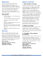
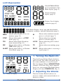
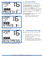
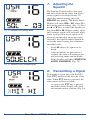
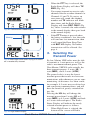
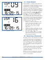
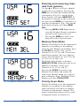
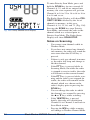
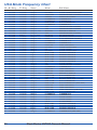
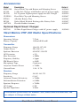
VHF200 VHF Radio
Owner’s Manual
Table of Contents
Introduction ........................................2
Service ...............................................2
Licensing............................................2
LCD Description.................................3
Turning the Radio On ........................3
Adjusting the Volume .........................3
Receive Mode....................................4
Changing Channels ...........................4
Channel Descriptions.........................5
Changing Between USA,
International and Canadian Modes....5
Adjusting the Squelch ........................6
Transmitting a Signal .........................6
Selecting the Transmit Power............7
Battery Level Display .........................8
Weather Mode ...................................9
Weather Alert ...................................10
16/9 Operation .................................11
Triple Watch Mode...........................12
Scanning Channels..........................12
STEP Mode .....................................15
Keypad Lock ....................................16
Restore Factory Settings .................16
Time Out Transmit Setting ...............17
Display Back-Light ...........................17
Battery Options for the VHF200 ......17
Maintenance ....................................18
Troubleshooting Guide.....................19
USA Frequency Chart......................20
International Frequency Chart .........21
Canadian Frequency Chart .............22
WX Frequency Chart .......................23
Accessories and Parts .....................24
Specifications...................................24
Warnings and Safety Precautions ...25
Emergency Communications...........26
Welcome!
Thank you for purchasing the West
Marine VHF200. This product was
designed and built for boaters to use in
the harsh marine environment. With proper care this product should provide you
with years of trouble-free operation.
Your satisfaction with this product is
backed by the entire West Marine organization worldwide.
Remember:
•
•
•
•
•
Safety and distress calls take priority
over all others.
You must monitor Channel 16 when
you are not operating on another
channel.
False or fraudulent distress calls are
prohibited under law.
Information overheard but not intended for you cannot lawfully be used in
any way.
Indecent or profane language is prohibited.
Service:
In the event that the radio fails to perform, or needs servicing, please send
directly to our Electronics Repair Center
in Hollister, CA. Be sure to include your
return mailing information and a detailed
accounting of the problems experienced
and/or the service requested.
West Marine
Electronics Repair Center
2395 Bert Court
Hollister, CA 95023
2
Radio Licenses:
1. Ship Station License
An FCC ship station license is no longer
required for any vessel traveling in US
waters which uses a VHF marine radio,
RADAR, EPIRB, and which is not
required to carry radio equipment. A
license is necessary however for a DSC
MMSI number, or for any vessel required
to carry a marine radio on an international
voyage, carrying a HF single side band
radiotelephone or marine satellite terminal. For more information, see the FCC’s
Fact Sheet PR 5000 #14. FCC license
forms, including applications for ship
(506) and land station licenses can be
downloaded via the Internet at
www.fcc.gov/forms. To obtain a form
from the FCC, call (888) 225-5322.
2. Radio Call Sign
Currently the FCC does not require recreational boaters to have a Ship Radio
Station License. The USCG recommends
that the boat’s registration number and the
state to be used.
3. Canadian Ship Station
Licensing
You do not need a license if your vessel is
not operated in sovereign waters of a
country other than Canada or the USA. If
you do need a license, contact their nearest field office or regional office or write:
Industry Canada
Radio Regulatory Branch
Attn: DOSP
300 Slater Street
Ottawa, Ontario
Canada, K1A OCA
West Marine VHF200 Owner’s Manual
LCD Description
USA/INTERNATIONAL/CANADIAN (UIC)
Mode display (page 5)
Channel Number
display (page 4)
Battery Level display
indicator (page 8)
LCD Display
Radio Status Display; shows long and short channel
descriptions, warnings, and radio information (page 5)
Shown when channel is in scan
memory (page 14)
STEP Shown when radio is in STEP
mode (page 15)
Shown when Triple Watch has
TRI
been selected (Page 12)
Shown when radio is in Weather
WX
(WX) Mode (page 9)
ALERT Shown when radio is in Weather
Alert Mode (page 10)
MEM
M
L
LOCK
TX
BUSY
Shown when medium transmit
power is selected (page 7)
Shown when low transmit
power is selected (page 7)
Shown when keypad is locked
(page 16)
Shown when transmitting (page
6)
Shown when radio is receiving a
signal (page 3)
1. Turning the Radio On
Turn the Power/Volume Knob clockwise
until it clicks. The radio will power up in
the same condition as it was last used.
The last Channel Mode (USA/INT/CAN),
Channel, TX Power, Key Lock, Squelch
Level, etc. are restored. The Radio Status
Display will show POWER ON. (Fig. 1)
2. Adjusting the Volume
Fig. 1: Power On Display
Turn the Volume Knob clockwise to
increase volume and counterclockwise to
decrease volume.
West Marine VHF200 Owner’s Manual
3
3. Receive Mode
When the radio receives a signal, the
Radio Status Display will show the message RECEIVE (Fig. 3a) for three seconds before reverting to the channel
description. The BUSY indicator will also
be shown. This is an indication that you
should not transmit until the BUSY indicator is not showing.
When the signal ceases the radio will display STAND BY. (Fig. 3b)
• After three seconds, the display
returns to the channel name.
Fig. 3a: Receive Display
Fig. 3b: Stand By Display
4. Changing Channels
To change channels, press the ▲ or ▼
keys.
• If the ▲ or ▼ key is pressed for
more than one second, the channel
will change rapidly.
• The radio displays memory status
and TX Power status of the channel
as you change the channels. (Fig. 4)
Fig. 4: Channel number and memory status
4
West Marine VHF200 Owner’s Manual
5. Channel Descriptions
Fig. 5: Current Channel, MAR OPER Display
The Radio Status Display indicates the
type of channel you have selected with
both a long and a short description. (Fig.
5) The long description will scroll from
right to left, and will be replaced by a
shorter description that stays in the Radio
Status Display. There is no universal
agreement on how to describe each channel, and some channels have different
purposes depending on where you’re
located in the US, but we’ve done our
best to provide helpful information. See
the appendix for a complete list of long
and short channel descriptions (pp. 20-23)
• Channels used by recreational boaters
for ship to ship conversations are listed as NON-COMMERCIAL in the
description. Examples are Channels
68, 69, 71, and 72.
6. Changing Between
USA, International,
and Canadian Modes
Fig. 6a: Selecting USA Mode
Fig. 6b: Select
International Mode
Fig. 6c: Select
Canadian Mode
Different areas of the world use different
VHF frequencies, although the channel
designation (1–88) may be the same.
There are three modes: USA,
International, and Canadian. Press and
hold the UIC key for two seconds to
change from USA to International to
Canadian Modes in turn.
• When Country Mode is changed,
Channel 16 is automatically selected,
not the last channel used. (Fig.
6a–6c)
• The Radio Status Display will verify
your selection with SEL USA, SEL
INTERNATIONAL, and SEL
CANADIAN.
West Marine VHF200 Owner’s Manual
5
7. Adjusting the
Squelch
Fig. 7a: Squelch Level Setting Mode
The Squelch Control reduces the static
and noise heard on the radio, but allows
strong signals to be heard clearly. To
adjust the squelch setting, press the
SQL/UIC key quickly. The Radio Status
Display will show SQL - 0X, where X is
the current squelch setting. (Fig. 7a) Press
the ▲ or ▼ keys to adjust the squelch setting from 00 to 08. Higher settings allow
only stronger signals will be heard, while
lower settings allow weak signals to be
received (and possibly annoying static).
Generally, the squelch control should be
set for the lowest setting that eliminates
unwanted static.
• Level 00 allows all signals to be
heard.
• After no buttons are pressed for 3
seconds, the radio will return to normal receiving mode and the Radio
Status Display will show SQUELCH
LEVEL CHANGED. (Fig. 7b)
Fig. 7b: Squelch Level Changed display
8. Transmitting a Signal
To transmit a signal, press the Push-ToTalk (PTT) button on the left side of the
radio. When PTT button is released, the
radio returns to Receive Mode.
• As soon as the PTT key is pressed,
the Radio Status Display will show
the transmit power selected. (Fig. 8a)
Fig. 8a: Transmitting at High Transmit Power
6
West Marine VHF200 Owner’s Manual
•
•
Fig. 8b: Transmission Ended Display
•
Blinking
When the PTT key is released, the
Radio Status Display will show TX
END (Fig. 8b)
You cannot transmit on receive-only
channels like the weather channels or
Channels 15 and 70. If you try, an
error tone will sound, the channel
number and TX indicator will blink
three times and the Radio Status
Display will show REC ONLY (Fig
8c). After 3 seconds, the radio returns
to the normal display, then goes back
to the normal display.
If the PTT button is pressed when
the battery condition is low, the radio
will send one last transmission, then
it will sound the Error Beep Tone
with BAT LO display. No further
transmission will be allowed. See
page 8.
9. Selecting the
Transmit Power
Fig. 8c: Message shown when trying to transmit
on a receive-only channel
Fig. 9a: High Power Display
By law, Marine VHF radios must be able
to transmit at 1 watt power as well as the
radio’s maximum transmit power. The
West Marine VHF200 radio actually has
three transmit powers: 5 watts (HI), 1
watt (MED), and 0.5 watts (LOW).
The general rule is to use the lowest
transmit power that results in clear communications with whomever you are communicating. At distances less than a mile,
for example, 0.5 watts may result in clear
and consistent communications, and will
have the benefit of greatly extended battery life.
Pressing the H/L key will change the
transmit power from 5 watts (HI) to 1
watt (MED) to 0.5 watts (LOW) and back
to 5 watts with each press. The Radio
Status Display will indicate the newly
selected transmit power as follows:
• When High Power is selected, the
bottom of the screen will Radio
West Marine VHF200 Owner’s Manual
7
Status Display will show XMIT HI
for three seconds. (Fig. 9a)
• When Medium Power is selected, the
Radio Status Display will show
XMIT MED for three seconds and the
M indicator will show. (Fig. 9b)
• When Low Power is selected, the
Radio Status Display will show
XMIT LOW for three seconds and
the L indicator will show. (Fig. 9c)
Certain channels are limited by law to 1
watt transmit power: USA Mode Channel
13, 17, 67, 77; INT Mode Channel 15, 17;
CAN Mode Channel 13, 15, 17, 20, 66,
77. Therefore, the radio will automatically
select 1 watt power when operating on
these channels, and efforts to change the
transmit power will result in the error tone.
• You cannot change the transmit
power setting on channels which are
receive-only channels: all weather
channels; USA Mode Channel 15,
70; INT Mode Channel 70; CAN
Mode Channel 70.
• Pressing the H/L key while scanning
or while in the Weather Mode will
result in the error tone and transmit
power will not change.
Fig. 9b: Medium Power Display
Fig. 9c: Low Power Display
10. Battery Level Display
Blinking
Fig. 10: Low Battery Warning Display
8
The battery level is checked periodically
and is shown using the Battery Level
Indicator (1–3 bars). More bars indicate
more battery capacity is left.
• When the battery capacity is very
low, the low battery warning alarm
will sound every 10 seconds, the low
battery message LOW BATT will be
shown on the Radio Status Display,
and the battery indicator will blink.
(Fig. 10)
• When the low battery warning message is displayed, the radio allows
one final transmission but it will not
allow further transmissions.
West Marine VHF200 Owner’s Manual
11. Weather Mode
Fig. 11a: Weather Mode Display
Fig. 11b: Marine Mode Display
Virtually all areas of the US and many
areas around the world are covered by
VHF weather reports on one of 10 channels. These reports provide current conditions, forecasts, and warnings of dangerous weather 24 hours per day.
Press and release the WX/ALERT key to
toggle between Weather and Marine
Modes. In Weather Mode the Radio
Status Display will show WX MODE for
three seconds and the WX indicator will
be shown. (Fig. 11a) When switching
back to Marine Mode, the Radio Status
Display will show USA MODE or INT
MODE or CAN MODE for three seconds. (Fig. 11b)
• While in Weather Mode, use the ▲ or
▼ keys to select from ten weather
channels. Most areas of the US are
covered by Weather Channels 01, 02,
and 03. The Radio Status Display
will verify which channel you’ve
selected (WEATHER1) as you
change channels.
• If you press the 16/9/TRI key while
in weather Mode, the radio will
change from the current weather
channel to Channel 16, then to
Channel 9, and then back to the
weather channel. The WX indicator
will flash, indicating that you are still
in weather Mode, while listening to
Channels 16 and 9.
• While in Weather Mode, the MEM,
UIC, SCAN, H/L keys will not work.
If they are pressed , the radio will
sound an error tone.
West Marine VHF200 Owner’s Manual
9
12. Weather Alert
Fig. 12a: Normal Channel Display
Fig. 12b: Weather Alert On
Weather Alert is a safety function that
allows the radio to monitor the local
weather channel for NOAA Weather
Alerts, while allowing you to listen to
other channels.
To set or cancel the Weather Alert function, press and hold the WX/ALERT key.
The display will switch from the current
channel display (Fig. 12a) to the Weather
Alert display for three seconds. The Radio
Status Display will show WX ALERT
ON. After three seconds, the display will
switch back to the current channel display. (Fig. 12b)
While in Weather Alert Mode, the radio
will check the last-used weather channel
for alert tones every seven seconds. When
an alert tone is detected, the radio will
cancel the Alert option and change to the
weather channel. It will also sound an
alert detect alarm at maximum volume for
10 seconds.
• If you’re using Weather Mode, and
the Alert option is on, the radio will
mute the speaker even though there is
a signal, until an alert tone is detected. This allows you to be aware of
alerts, but without having to listen to
the weather continuously. (Fig. 12c)
• When an alert tone is detected, the
Scan and Triple Watch functions are
cancelled.
Fig. 12c: Weather Alert Display in Weather
Mode
10
West Marine VHF200 Owner’s Manual
13. 16/9 Operation
Fig. 13a: Current Channel, MAR OPER Display
Fig. 13b: Channel 16, DISTRESS Display
By pressing the 16/9/TRI key briefly, the
radio will change from Channel 16 to
Channel 9 and back to the start channel.
For example, if the start channel is
Channel 24, pressing the 16/9/TRI will
change the channel from 24 to 16 to 9 and
back to 24. (Fig. 13a–13c)
• If the 16/9/TRI key is pressed in
Weather Mode, Weather Mode is
paused temporally and the radio will
change from Channel 16 to Channel
09 to Weather Mode in turn. While
Channel 16 and 09 are displayed, the
WX icon will blink to indicate that
Weather Mode is temporally paused.
• If the 16/9/TRI key is pressed while
scanning, scanning is paused temporarily and it changes from
Scanning Mode to Channel 16 to
Channel 09 to Scanning Mode in
turn.
• If the 16/9/TRI key is pressed in
Triple Watch, Triple Watch operation
is paused temporarily and it changes
from Triple Watch to Channel 16 to
Channel 09 and back to Triple Watch
in turn.
Fig. 13c: Channel 9, NON COML Display
West Marine VHF200 Owner’s Manual
11
14. Triple Watch
Fig. 14a: Triple Watch Display
Fig. 14b: Triple Watch Display
Triple Watch is a handy feature that lets
you monitor a channel of interest to you,
yet maintain a watch on Channels 9 and
16. Let’s say you need to monitor
Channel 15, the Environmental Channel,
but don’t want to miss important safety or
distress messages on Channel 16. Simply
select Channel 15 with the ▲ or ▼ keys,
then press and hold the 16/9/TRI key.
The TRI icon will be displayed. Every
two seconds, the radio will quickly monitor Channels 16 and 9 before returning to
your selected channel. The Radio Status
Display will show the three channels
being monitored. (Fig. 14a)
• If there is traffic on Channel 9, the
radio will monitor Channel 9 until
the signal stops while checking
Channel 16 every two seconds.
(Fig. 14a)
• If there is traffic on Channel 16, the
radio will monitor Channel 16 until
the signal stops. (Fig. 14b)
• Pressing the ▲ or ▼ keys in Triple
Watch will increment or decrement
the monitored channel.
15. Scanning Channels
Scanning allows you to monitor the traffic
or conversations on several channels in
quick succession. This can be helpful if
you’re trying to listing to fishing traffic
on several channels, or need to monitor
Race Committee traffic on Channels 68,
69, and 71.
As the radio detects traffic on any channel
in its scan list, it will pause until three
seconds after the last transmission, then
continue scanning.
Before you can scan channels, you need
to store two or more channels into the
radio’s scan memory.
12
West Marine VHF200 Owner’s Manual
Entering and removing channels from memory
Fig. 15a: Channel 16 added to scan memory
Use the ▲ or ▼ keys to select a channel
to enter into scan memory. Pressing the
MEM key will enter the channel into the
scan memory (Fig 15a), and the Radio
Status Display will show MEM SET. If
the channel is currently in the scan memory, pressing the MEM key will remove it
from the scan memory. (Fig. 15b) and the
Radio Status Display will show MEM
DEL.
• Pressing MEM in WX Mode doesn’t
store the Weather Channel in memory
and will result in the error tone.
• Pressing the MEM key while scanning will result in the error tone.
Memory Scan Mode
Fig. 15b: Channel 16 deleted from scan mem.
Fig. 15c: Memory Channel Scan Display
Memory Scan Mode scans the memorized
channels in ascending (or descending)
order. To enter Memory Scan Mode, press
the SCAN key briefly. (Fig. 15c) If
Channels 6, 16, 22, 68, and 72 have been
entered into memory, the scan sequence
will go from Channel 6 to 16 to 22 to 68
to 72 to 6 to 16 and so on.
The Radio Status Display will show
MEMORY SCAN followed by the list of
channels in memory (in this case,
Channels 6, 16, 22, 68, and 72).
Pressing the SCAN key briefly stops
Memory Scan Mode, and returns the
radio to the channel which was selected
prior to Memory Scan. The Radio Status
Display will show SCAN STOP.
Priority Scan Mode
Priority Scan Mode scans the memorized
channels in ascending (or descending)
order, but checks for traffic on Channel
16 between each memory channel. This
makes it more likely that you’ll be aware
of important traffic on Channel 16.
West Marine VHF200 Owner’s Manual
13
Fig. 15d: Priority Channel Scan Display
To enter Priority Scan Mode, press and
hold the SCAN key for two seconds. If
Channels 6, 22, and 68 are entered into
memory, the scan sequence will go from
Channel 6 to 16 to 22 to 16 to 68 to 16 to
6 to 16 and so on.
The Radio Status Display will show PRIORITY SCAN followed by the list of
channels in memory; in this case,
Channels 6, 16, 22, 68, and 72. (Fig. 15d)
Pressing the SCAN key stops Priority
Scan Mode, and returns the radio to the
channel which was selected prior to
Priority Scan Mode. The Radio Status
Display will show SCAN STOP.
Notes on Scanning
•
•
•
•
•
•
•
•
14
You cannot scan channels while in
Weather Mode.
If you have not entered any channels
into memory, the radio will sound the
error tone when the SCAN key is
pressed.
If there is only one channel in memory, the radio will beep and change to
the that channel.
If the PTT key is pressed while in
Scanning Mode, but while the radio
is stopped to receive traffic, the radio
will transmit on the current channel.
If the PTT key is pressed while scanning and the radio is not stopped for
traffic, the radio will transmit on the
channel which was shown on the
radio’s display prior to pressing the
SCAN key.
You can change the order in which
the channels are scanned by pressing
the ▲ or ▼ keys while scanning.
If the 16/9/TRI key is pressed
briefly, the radio will switch from
Channel 16 to Channel 9 and back to
Scan Mode in turn.
Pressing the WX key while scanning
will change to Weather Channel Mode.
West Marine VHF200 Owner’s Manual
•
•
•
Pressing the SQL/UIC key briefly
(less than one second) while scanning, will change to Squelch Change
Mode. The LCD display will show
the squelch level and will continue to
scan.
If SQL/UIC key is pressed for over
two seconds while scanning, the
radio will stop scanning and change
to Change Country Mode. (page 5)
If the MEM key or the H/L key is
pressed while scanning, the radio will
make an error tone and the key press
will be ignored.
16. Step Mode
Fig. 16a: Step On Display
Fig. 16b: Step Off Display
Marine radios offer a wide range of channels, but frequently there are only 5 to 10
of interest to most recreational boaters.
Step Mode allows you to work with only
those channels in scan memory while
ignoring others.
Press and hold the MEM/STEP key to
toggle the Step Mode on or off.
When Step Mode is on (STEP icon
appears), press the ▲ or ▼ keys to select
the scan memory channels.
• When Step Mode is selected, the
Radio Status Display will show
STEP ON for three seconds. (Fig.
16a)
• When the Step Mode is deselected,
the Radio Status Display will show
STEP OFF for three seconds. (Fig
16b) and the STEP indicator will
turn off.
Note: Step Mode can be confusing if
you’re unaware that it is selected. If you
can’t seem to select the channels that you
want, check for the STEP indicator on
the display. Press and hold MEM/STEP
to exit Step Mode.
West Marine VHF200 Owner’s Manual
15
17. Keypad Lock
Fig. 18: Key Lock Display Display
There may be times when you don’t want
to inadvertently press a key on the radio’s
keypad. In this case, you can select
Keypad Lock by pressing the I key
(below the PTT key on the left hand side)
for two seconds. This will cause the keypad lock indicator two be shown, and the
Radio Status Display will show KEY
LOCK ON. (Fig. 18) While the keypad is
locked, the keypad will not respond to
key presses. Press the I key for another
two seconds to unlock the keypad. This
will extinguish the Lock indicator, and
show KEY LOCK OFF on the Radio
Status Display.
• When keys are locked, only the PTT
key and I key function.
• Locking the keypad can be confusing. When the radio doesn’t seem to
be operating properly, see if the
LOCK indicator is on.
18. Restore Factory
Settings
To reset all of the customized settings to
the original factory settings, hold the
16/9/TRI key down while turning on the
radio. Customized settings and channels
stored in memory will be lost when factory settings are restored.
Factory Settings
Country Mode ……………………USA
Last Used Channel …………Channel 16
WX Mode ……………………Disabled
Last Used WX Channel ………………01
Key Lock ……………………Disabled
Triple Watch ……………………Disabled
……………………Disabled
WX Alert
STEP …………………………Disabled
TX Output Power
………………High
All Channel MEM
…………Disabled
Squelch Level …………………………4
TOT time ……………………5 minutes
16
West Marine VHF200 Owner’s Manual
19. Time out Transmit
Setting
Blinking
Fig. 19a: TOT Set Display
Fig. 19b: Transmit Time Exceeded display
Nothing is more disruptive to Marine
VHF communications than when some
boater has his or her microphone PTT
key pressed accidentally. The problem is
that there is no way to notify him that the
problem exists since the radio cannot
receive traffic.
The VHF200 has a Time Out Transmit
feature that allows you to set a maximum
period of PTT key press time before the
radio will revert to Receive Mode. This is
set at the factory at five minutes, but you
can enter any value from one to twenty
minutes, or turn off the feature entirely.
To change the Time Out Transmit setting,
press and hold the MEM key and turn the
power on. Set the TOT time by pressing
the ▲ or ▼ keys. (Fig. 20a)
• The TOT Range is 00, 01–20.
• 00=TOT off
• 01=1 minute
• 20=20 minutes
After setting the TOT, press the PTT button to save and exit to Receive Mode.
• If a transmission exceeds the TOT
time, the radio will stop the transmission and return to Receive Mode. The
message TRANSMIT TIME
EXCEEDED will show in the Radio
Status Display at the bottom of the
screen. (Fig. 20b)
20. Display Back-Light
If any key is pressed, the display and keypad light will turn on and remain on for
ten seconds after the last key press.
21. Battery Options for
the VHF200
The VHF200 comes with both the BP200
NiMH (Nickel Metal Hydride) rechargeWest Marine VHF200 Owner’s Manual
17
able battery back as well as an BT200
alkaline battery tray. For most use, the
BP200 battery pack will provide convenient, long life service, and will operate
your radio for approximately 12 hours on
a charge. The length of service depends
largely on how much time you spend
transmitting, and what transmit power
you use.
Charging the BP200
A feature of the NiMH pack is that you
can recharge at any time. The standard
charger SC200 will completely recharge
the BP200 battery pack in approximately
12 hours. If you need the radio prior to a
full charge, you can remove it from the
charger base at any state of charge. The
BP200 will not be damaged by extended
charge time.The best way to use the battery pack is to detach the battery pack
after full charge
In SC200, when the radio and BP200 are
placed in the SC200 charger base and
power is present, the LED on the front of
the charger base will be red.
The VHF200 also includes the DC200
Cigarette Lighter Cord. The DC200 can
power the SC200 charger base from any
cigarette lighter socket. The DC200 plugs
into the charger base in the same socket
as the AC power supply.
Use of the Optional RSC200
Rapid Smart Charger
When the radio and BP200 are placed in
the RSC200 charger base and power is
present, the LED on the front of the
charger base will be red if the power is on
but the radio is being charged, or green if
the radio is fully charged.
BT200 Alkaline Battery Pack
The BT200 alkaline battery pack can be
used as a backup to the BP200 battery
pack when charging may not be possible
or convenient. It holds 6 AA batteries.
When the alkaline batteries have discharged, dispose of them safely. They
cannot be recharged using the supplied
chargers.
Make sure to observe the polarity shown
on the inside of the alkaline battery tray
when installing the batteries.
Alkaline batteries have excellent shelf life
when kept in a cool environment, but they
can leak under certain circumstances. If
you store your radio for extended periods,
we recommend that you remove the alkaline battery tray from the radio.
22. Maintenance
•
•
The VHF200 is designed to provide
years of trouble free operation with
virtually no maintenance. Follow
these simple procedures to ensure
that the VHF200 continues to deliver
top performance.
Rinse the VHF200 thoroughly with
fresh water after exposure to salt
water. Otherwise the radio’s keys,
switches, and controllers may
become inoperable due to salt crystallization.
Be Careful! The VHF200 employs
JIS 7 waterproof construction (submersion to 1 m. depth for 30 min.).
However, waterproofness cannot be
guaranteed over time. Extreme shock
(dropping, etc.) may crack the case or
dislodge or damage the seals.
For faster charging of the BP200 battery
pack, the optional RSC200 Rapid Smart
Charger can be used. It will completely
recharge the BP200 in 90 minutes or less,
depending on state of discharge. The
•
RSC200 is a “smart charger” and will not
damage the BP200 even if the radio is left
in the charger base for long periods. The
best way to use the battery pack is to
detach the battery pack after full charge.
The RSC200 can only be powered by AC
current.
18
West Marine VHF200 Owner’s Manual
•
Additionally, wear or improper battery pack installation can damage the
battery compartment seal.
Keep your battery contacts clean!
Wipe frequently. If visible corrosion
appears, polish with an emery cloth
or similar fine abrasive.
•
•
Never transmit without an antenna
attached to avoid damage to the radio.
Avoid using or placing the VHF200
in areas with temperatures below 20ºC (-4ºF) or above +60ºC
(+140ºF). Do not place in windshields, etc.
23. Troubleshooting Guide
Symptom:
Probable Cause:
Remedy:
Symptom:
Probable Cause:
Remedy:
Symptom:
Probable Cause:
Remedy:
Symptom:
Probable Cause 1:
Remedy 1:
Probable Cause 2:
Remedy 2:
Symptom:
Probable Cause:
Remedy:
Symptom:
Probable Cause:
Remedy:
Symptom:
Probable Cause:
Remedy:
The radio does not respond to key presses. The channel cannot be
changed.
Key Lock is on.
Press the I key (on the left side of the case, below the PTT key) for
three seconds to unlock the key pad.
You have arranged to communicate with another VHF radio user on a
specific channel, and you can’t hear them.
You and the other user are using different Country Codes.
Make sure that you are both using the same Country Mode (USA,
International, or Canadian). Several channels have the same numeric
designation, but are either on different frequencies or the channels are
used for different purposes. Channel 16, the Distress, Safety, and
Calling channel, is the same on all three bands.
You cannot change the transmit power setting.
You are on a channel which is limited to 1 watt transmit power (e.g. Ch.
13) or you are on a “receive only” channel (e.g. WX ).
Change to an unrestricted TX/RX channel.
The SCAN key does not start the scan function.
No channels are in the scan memory.
Use the MEM key to enter desired channels into the scan memory.
Squelch is not adjusted correctly.
Adjust the squelch to the point that background noise just disappears.
Radio just does not seem to be operating correctly.
The radio has become “confused” by an unusual pattern of key presses.
Turn off the radio. Hold down the 16/9/TRI key while turning the radio
on. This process will reset the radio to the original factory settings.
Radio will not power up.
The battery is exhausted.
Recharge the battery pack or use the BT200 alkaline battery tray with
fresh alkaline batteries.
You can hear transmissions, but the other radio cannot hear you.
The transmit power is set to low.
Use the H/L key to select a higher transmit power setting.
West Marine VHF200 Owner’s Manual
19
USA Mode Frequency Chart
Ch. Rx Freq
1
3
5
6
7
8
9
10
11
12
13
14
15
16
17
18
19
20
21
22
23
24
25
26
27
28
61
63
64
65
66
67
68
69
70
71
72
73
74
77
78
79
80
81
82
83
84
85
86
87
88
20
156.0500
156.1500
156.2500
156.3000
156.3500
156.4000
156.4500
156.5000
156.5500
156.6000
156.6500
156.7000
156.7500
156.8000
156.8500
156.9000
156.9500
157.0000
157.0500
157.1000
157.1500
161.8000
161.8500
161.9000
161.9500
162.0000
156.0750
156.1750
156.2250
156.2750
156.3250
156.3750
156.4250
156.4750
156.5250
156.5750
156.6250
156.6750
156.7250
156.8750
156.9250
156.9750
157.0250
157.0750
157.1250
157.1750
161.8250
161.8750
161.9250
161.9750
157.4250
Tx Freq
156.0500
156.1500
156.2500
156.3000
156.3500
156.4000
156.4500
156.5000
156.5500
156.6000
156.6500
156.7000
Inhibit
156.8000
156.8500
156.9000
156.9500
157.0000
157.0500
157.1000
157.1500
157.2000
157.2500
157.3000
157.3500
157.4000
156.0750
156.1750
156.2250
156.2750
156.3250
156.3750
156.4250
156.4750
Inhibit
156.5750
156.6250
156.6750
156.7250
156.8750
156.9250
156.9750
157.0250
157.0750
157.1250
157.1750
157.2250
157.2750
157.3250
157.3750
157.4250
Status
Simplex
Simplex
Simplex
Simplex
Simplex
Simplex
Simplex
Simplex
Simplex
Simplex
Simplex, 1 W
Simplex
Receive Only
Simplex
Simplex, 1 W
Simplex
Simplex
Simplex
Simplex
Simplex
Simplex
Duplex
Duplex
Duplex
Duplex
Duplex
Simplex
Simplex
Simplex
Simplex
Simplex
Simplex, 1 W
Simplex
Simplex
Receive Only
Simplex
Simplex
Simplex
Simplex
Simplex, 1 W
Simplex
Simplex
Simplex
Simplex
Simplex
Simplex
Duplex
Duplex
Duplex
Duplex
Simplex
Name
VTS/COML
CG ONLY
VTS/COML
SAFETY
COMMERCL
COMMERCL
NON COML
COMMERCL
VTS
VTS
BRG-BRG
VTS
ENVIRON
DISTRESS
GOVT
COMMERCL
COMMERCL
PORT OPR
CG ONLY
CG
CG ONLY
MAR OPER
MAR OPER
MAR OPER
MAR OPER
MAR OPER
CG
VTS
COMMERCL
PORT OPR
PORT OPR
BRG-BRG
NON COML
NON COML
DSC
NON COML
NON COML
PORT OPR
PORT OPR
PORT OPR
NON COML
COMMERCL
COMMERCL
USCG
USCG
USCG
MAR OPER
MAR OPER
MAR OPER
MAR OPER
COMMERCL
Full Name
VESSEL TRAFFIC SYSTEM/COMMERCIAL
COAST GUARD,GOVT ONLY
VESSEL TRAFFIC SYSTEM/COMMERCIAL
INTER-SHIP SAFETY
COMMERCIAL
COMMERCIAL
NON COMMERCIAL
COMMERCIAL
VESSEL TRAFFIC SYSTEM
VESSEL TRAFFIC SYSTEM
BRIDGE TO BRIDGE
VESSEL TRAFFIC SYSTEM
ENVIRONMENTAL
DISTRESS,SAFETY,CALLING
GOVT MARITIME CONTROL
COMMERCIAL
COMMERCIAL
PORT OPERATION
COAST GUARD ONLY
COAST GUARD
COAST GUARD ONLY
MARINE OPERATOR
MARINE OPERATOR
MARINE OPERATOR
MARINE OPERATOR
MARINE OPERATOR
COAST GUARD
VESSEL TRAFFIC SYSTEM
COMMERCIAL
PORT OPERATION
PORT OPERATION
BRIDGE TO BRIDGE
NON COMMERCIAL
NON COMMERCIAL
DIGITAL SELECTIVE CALLING
NON COMMERCIAL
NON COMMERCIAL (SHIP-SHIP)
PORT OPERATION
PORT OPERATION
PORT OPERATION (SHIP-SHIP)
NON COMMERCIAL
COMMERCIAL
COMMERCIAL
COAST GUARD
COAST GUARD
GOVERNMENT
MARINE OPERATOR
MARINE OPERATOR
MARINE OPERATOR
MARINE OPERATOR
COMMERCIAL (SHIP-SHIP)
West Marine VHF200 Owner’s Manual
International Mode Frequency Chart
Ch. Rx Freq
1
2
3
4
5
6
7
8
9
10
11
12
13
14
15
16
17
18
19
20
21
22
23
24
25
26
27
28
60
61
62
63
64
65
66
67
68
69
70
71
72
73
74
77
78
79
80
81
82
83
84
85
86
87
88
160.6500
160.7000
160.7500
160.8000
160.8500
156.3000
160.9500
156.4000
156.4500
156.5000
156.5500
156.6000
156.6500
156.7000
156.7500
156.8000
156.8500
161.5000
161.5500
161.6000
161.6500
161.7000
161.7500
161.8000
161.8500
161.9000
161.9500
162.0000
160.6250
160.6750
160.7250
160.7750
160.8250
160.8750
160.9250
156.3750
156.4250
156.4750
156.5250
156.5750
156.6250
156.6750
156.7250
156.8750
161.5250
161.5750
161.6250
161.6750
161.7250
161.7750
161.8250
161.8750
161.9250
161.9750
162.0250
Tx Freq
156.0500
156.1000
156.1500
156.2000
156.2500
156.3000
156.3500
156.4000
156.4500
156.5000
156.5500
156.6000
156.6500
156.7000
156.7500
156.8000
156.8500
156.9000
156.9500
157.0000
157.0500
157.1000
157.1500
157.2000
157.2500
157.3000
157.3500
157.4000
156.0250
156.0750
156.1250
156.1750
156.2250
156.2750
156.3250
156.3750
156.4250
156.4750
Inhibit
156.5750
156.6250
156.6750
156.7250
156.8750
156.9250
156.9750
157.0250
157.0750
157.1250
157.1750
157.2250
157.2750
157.3250
157.3750
157.4250
Status
Duplex
Duplex
Duplex
Duplex
Duplex
Simplex
Duplex
Simplex
Simplex
Simplex
Simplex
Simplex
Simplex
Simplex
Simplex, 1 W
Simplex
Simplex, 1 W
Duplex
Duplex
Duplex
Duplex
Duplex
Duplex
Duplex
Duplex
Duplex
Duplex
Duplex
Duplex
Duplex
Duplex
Duplex
Duplex
Duplex
Duplex
Simplex
Simplex
Simplex
Receive Only
Simplex
Simplex
Simplex
Simplex
Simplex
Duplex
Duplex
Duplex
Duplex
Duplex
Duplex
Duplex
Duplex
Duplex
Duplex
Duplex
Name
MAR OPER
MAR OPER
MAR OPER
MAR OPER
MAR OPER
SAFETY
MAR OPER
COMMERCL
CALLING
COMMERCL
VTS
VTS
BRG-BRG
VTS
ENVIRON
DISTRESS
GOVT
PORT OPR
COMMERCL
PORT OPR
PORT OPR
PORT OPR
MAR OPER
MAR OPER
MAR OPER
MAR OPER
MAR OPER
MAR OPER
MAR OPER
MAR OPER
MAR OPER
MAR OPER
MAR OPER
MAR OPER
MAR OPER
BRG-BRG
NON COML
NON COML
DSC
NON COML
NON COML
PORT OPR
PORT OPR
PORT OPR
PORT OPR
PORT OPR
PORT OPR
PORT OPR
PORT OPR
PORT OPR
MAR OPER
MAR OPER
MAR OPER
MAR OPER
MAR OPER
Full Name
MARINE OPERATOR
MARINE OPERATOR
MARINE OPERATOR
MARINE OPERATOR
MARINE OPERATOR
INTER-SHIP SAFETY
MARINE OPERATOR
COMMERCIAL (SHIP-SHIP)
BOATER CALLING CHANNEL
COMMERCIAL
VESSEL TRAFFIC SYSTEM
VESSEL TRAFFIC SYSTEM
BRIDGE TO BRIDGE
VESSEL TRAFFIC SYSTEM
ENVIRONMENTAL
DISTRESS,SAFETY,CALLING
GOVT MARITIME CONTROL
PORT OPERATION
COMMERCIAL
PORT OPERATION
PORT OPERATION
PORT OPERATION
MARINE OPERATOR
MARINE OPERATOR
MARINE OPERATOR
MARINE OPERATOR
MARINE OPERATOR
MARINE OPERATOR
MARINE OPERATOR
MARINE OPERATOR
MARINE OPERATOR
MARINE OPERATOR
MARINE OPERATOR
MARINE OPERATOR
MARINE OPERATOR
BRIDGE TO BRIDGE
NON COMMERCIAL
NON COMMERCIAL
DIGITAL SELECTIVE CALLING
NON COMMERCIAL
NON COMMERCIAL
PORT OPERATION
PORT OPERATION
PORT OPERATION (SHIP-SHIP)
PORT OPERATION
PORT OPERATION
PORT OPERATION
PORT OPERATION
PORT OPERATION
PORT OPERATION
MARINE OPERATOR
MARINE OPERATOR
MARINE OPERATOR
MARINE OPERATOR
MARINE OPERATOR
West Marine VHF200 Owner’s Manual
21
Canadian Mode Frequency Chart
Ch. Rx Freq
1
2
3
4
5
6
7
8
9
10
11
12
13
14
15
16
17
18
19
20
21
22
23
24
25
26
27
28
60
61
62
64
65
66
67
68
69
70
71
72
73
74
77
78
79
80
81
82
83
84
85
86
87
88
22
160.6500
160.7000
160.7500
156.2000
156.2500
156.3000
156.3500
156.4000
156.4500
156.5000
156.5500
156.6000
156.6500
156.7000
156.7500
156.8000
156.8500
156.9000
156.9500
161.6000
157.0500
157.1000
161.7500
161.8000
161.8500
161.9000
161.9500
162.0000
160.6250
156.0750
156.1250
156.2250
156.2750
156.3250
156.3750
156.4250
156.4750
156.5250
156.5750
156.6250
156.6750
156.7250
156.8750
156.9250
156.9750
157.0250
157.0750
157.1250
157.1750
161.8250
161.8750
161.9250
161.9750
162.0250
Tx Freq
156.0500
156.1000
156.1500
156.2000
156.2500
156.3000
156.3500
156.4000
156.4500
156.5000
156.5500
156.6000
156.6500
156.7000
156.7500
156.8000
156.8500
156.9000
156.9500
157.0000
157.0500
157.1000
157.1500
157.2000
157.2500
157.3000
157.3500
157.4000
156.0250
156.0750
156.1250
156.2250
156.2750
156.3250
156.3750
156.4250
156.4750
Inhibit
156.5750
156.6250
156.6750
156.7250
156.8750
156.9250
156.9750
157.0250
157.0750
157.1250
157.1750
157.2250
157.2750
157.3250
157.3750
157.4250
Status
Duplex
Duplex
Duplex
Simplex
Simplex
Simplex
Simplex
Simplex
Simplex
Simplex
Simplex
Simplex
Simplex, 1 W
Simplex
Simplex, 1 W
Simplex
Simplex, 1 W
Simplex
Simplex
Duplex, 1 W
Simplex
Simplex
Duplex
Duplex
Duplex
Duplex
Duplex
Duplex
Duplex
Simplex
Simplex
Simplex
Simplex
Simplex, 1 W
Simplex
Simplex
Simplex
Receive Only
Simplex
Simplex
Simplex
Simplex
Simplex, 1 W
Simplex
Simplex
Simplex
Simplex
Simplex
Simplex
Duplex
Duplex
Duplex
Duplex
Duplex
Name
MAR OPER
MAR OPER
MAR OPER
CCG
VTS
SAFETY
COMMERCL
COMMERCL
CALLING
COMMERCL
VTS
VTS
BRG-BRG
VTS
ENVIRON
DISTRESS
SAR
COMMERCL
CCG
PORT OPR
CCG
CCG
CCG
MAR OPER
MAR OPER
MAR OPER
MAR OPER
MAR OPER
MAR OPER
CCG
CCG
MAR OPER
RESCUE
PORT OPR
BRG-BRG
NON COML
NON COML
DSC
NON COML
NON COML
PORT OPR
PORT OPR
PORT OPR
SHP-SHP
SHP-SHP
SHP-SHP
CCG
CCG
CCG
MAR OPER
MAR OPER
MAR OPER
MAR OPER
MAR OPER
Full Name
MARINE OPERATOR
MARINE OPERATOR
MARINE OPERATOR
COAST GUARD
VESSEL TRAFFIC SYSTEM
INTER-SHIP SAFETY
COMMERCIAL
COMMERCIAL
BOATER CALLING CHANNEL
COMMERCIAL
VESSEL TRAFFIC SYSTEM
VESSEL TRAFFIC SYSTEM
BRIDGE TO BRIDGE
VESSEL TRAFFIC SYSTEM
ENVIRONMENTAL
DISTRESS,SAFETY,CALLING
STATE CONTROL
COMMERCIAL
CANADIAN COAST GUARD
PORT OPERATION
COAST GUARD
COAST GUARD
COAST GUARD
MARINE OPERATOR
MARINE OPERATOR
MARINE OPERATOR
MARINE OPERATOR
MARINE OPERATOR
MARINE OPERATOR
COAST GUARD
COAST GUARD
MARINE OPERATOR
SEARCH AND RESCUE
PORT OPERATION
BRIDGE TO BRIDGE
NON COMMERCIAL
NON COMMERCIAL
DIGITAL SELECTIVE CALLING
NON COMMERCIAL
NON COMMERCIAL
PORT OPERATION
PORT OPERATION
PORT OPERATION
INTER SHIP
INTER SHIP
INTER SHIP
COAST GUARD
COAST GUARD
COAST GUARD
MARINE OPERATOR
MARINE OPERATOR
MARINE OPERATOR
MARINE OPERATOR
MARINE OPERATOR
West Marine VHF200 Owner’s Manual
WX Frequency Chart
Channel No.
WX01
WX02
WX03
WX04
WX05
WX06
WX07
WX08
WX09
WX10
(MHz)
162.5500
162.4000
162.4750
162.4250
162.4500
162.5000
162.5250
161.6500
161.7750
163.2750
Name
WEATHER1
WEATHER2
WEATHER3
WEATHER4
WEATHER5
WEATHER6
WEATHER7
WEATHER8
WEATHER9
WEATHR10
West Marine VHF200 Owner’s Manual
23
Accessories
Model
SWIV200
SC200
DC200
CLIP200
BT200
BP200
ANT200
Description
Swivel Belt Clip with Button and Mounting Screw
12 Hr. Std. Charger with Bucket and AC power supply
DC Cigarette Lighter power supply for Std. Charger
Fixed Belt Clip with Mounting Screws
Alkaline Battery Tray
Nickel Metal Hydride Rechargeable Battery Pack
Flexible Rubber Antenna
Optional Rapid Smart Charger:
RSC200
90 Min. Rapid Smart Charger with AC power supply
Order #
3895638
3895463
3895554
3895687
3895562
3895497
3895547
3895489
West Marine VHF 200 Radio Specifications
Dimensions
Operating Voltage
Battery Capacity
7.2Vdc
1350mAH Ni-mH
Transmitter
Frequency Range
Output Power
Spurious Emission
AF Distortion
Max Deviation
Frequency Stability
FM Hum & Noise
Microphone Type
Adjacent Channel Power
Current Drain
156.025-157.425
5W /1W/ 0.5
65@5W/ 55@1W
< 5%
< 5KHz
< 5ppm
> 40dB
Condenser
> 70dBc
1.5A / 0.7A
Receiver
Frequency Range
Sensitivity
Adjacent Channel Selectivity
Intermodulation Distortion
Spurious Response
AF Output
Speaker Impedance
56.050-163.275
0.2uV
> 70dBc
> 65dBc
> 70dBc
0.5W
8 Ohm
Performance specifications are nominal value, unless otherwise indicated, and
are subject to change without notice.
24
West Marine VHF200 Owner’s Manual
Warning: Your West Marine VHF200
generates RF electromagnetic energy
when transmitting. This radio was
designed to meet the FCC’s rules and regulations for the maximum permissible
exposure to radio frequency energy. This
design was tested and found to be compliant to the strict requirements established
by the FCC.
This radio was designed for and is classified as “Occupational Use Only”, meaning it must be used only during the course
of employment by individuals aware of
the hazards, and the ways to minimize
such hazards. This radio is not intended
for use by the “General Population” in an
uncontrolled environment. It’s use is
restricted to work related operations only
where the radio operator must have the
knowledge to control his or her exposure
conditions for satisfying the higher exposure limit allowed for Occupational
Users.
Caution: It is up to the user to properly
operate this transmitter to ensure safe
operation. Please adhere to the following
to ensure that your exposure to RF electromagnetic energy is within the FCC
allowable limits:
• DO NOT operate the radio without a
proper antenna attached, as this may
damage the radio and may also cause
you to exceed FCC RF exposure limits. A proper antenna is the antenna
supplied with this radio by the manufacturer or an antenna specifically
authorized by the manufacturer to use
with this radio.
• DO NOT transmit for more than 50%
of the total radio use time.
Transmitting more than 50% of the
time can cause FCC RF exposure
compliance requirements to be
exceeded. The radio is transmitting
when the “TX indicator” is displayed
on the screen. You can cause the
radio to transmit by pressing the
“PTT” switch.
• ALWAYS maintain at least a 1-inch
(2.5 cm) separation distance between
your body (including the face and
eyes) and any surface of the radio.
• NEVER allow the antenna to touch
the human body or to come within 1
inch when the transmitter is active.
• NEVER allow children to operate the
radio without adult supervision and
the knowledge of the following safety guidelines.
This radio is approved for use with the
specific belt-clip tested for body-worn
SAR compliance. Other belt clips or
body-worn accessories may not comply
and should be avoided.
Notice: This equipment has been tested
and found to comply with the limits for a
Class B digital device, pursuant to Part 15
of the FCC Rules. These limits are
designed to provide reasonable protection
against harmful interference in a residential installation. This equipment generates,
uses and can radiate radio frequency energy and, if not installed and used in accordance with the instructions, may cause
harmful interference to radio communications. However, there is no guarantee that
interference will not occur in a particular
installation. If this equipment does cause
harmful interference to radio or television
reception, which can be determined by
turning the equipment off and on, the user
is encouraged to try to correct the interference by one or more of the following
measures:
— Increase the separation between the
equipment and receiver.
— Connect the equipment into an outlet
on a circuit different from that to
which the receiver is connected.
— Consult the dealer or an experienced
marine electronics technician for
help.
West Marine VHF200 Owner’s Manual
25
24. Emergency
Communications
One of the most important reasons to
have a VHF radio on board your boat is
so you can make distress calls to rescue
agencies like the US Coast Guard, State
Boating Authorities, County Sheriffs, and
towing organizations. There are three
acknowledged levels of severity when
making an emergency call, and it’s important to know what to do if you should
have to make an emergency call, and
what to do if you hear one.
An excellent source for information on
marine communications is Chapman
Piloting, Seamanship, and Small Boat
Handling. We recommend that you consult Chapman’s for more information, and
also consult the web at one of the following web sites:
www.boatingsafety.com
www.boatsafe.com/nauticalknowhow/radi
o.htm
26
Mayday for Distress
Communications
Mayday calls are only for when your vessel or crew face “grave and imminent
danger, and immediate help is required”.
Therefore, you should not transmit a
Mayday call unless you’re likely to lose a
life or your boat.
Procedure for making a Distress
Call:
Select Channel 16 and high transmit
power.
Transmit as follows:
1. “Mayday, Mayday, Mayday”.
2. “This is (Name of Vessel)”. Repeat
three times.
3. “(Your call sign or other indication of
the vessel)”. Repeat three times.
4. “Located at (your position)”. The
position can be in latitude and longitude, or can be in reference to a
known object. Be specific. “Near a
Red buoy” or “South of the
Lighthouse” is too easy to misinterpret.
5. State “(The nature of the distress and
assistance required.)”. Examples: taking on water, medical emergency,
fire, dismasting, aground in surf.
6. State “(Any other information which
might facilitate the rescue)”.
Examples: # of adults and children on
board, other communications devices,
life raft on board, color of vessel,
size of vessel, # of injuries, type of
help or equipment needed.
After making a Mayday call, allow the
Coast Guard, other rescue agencies, or
other boaters to contact you. If you don’t
hear from anyone in a minute, repeat your
message.
West Marine VHF200 Owner’s Manual
Pan Pan for Urgency
Messages
Since Mayday calls are only for “grave
and imminent danger”, what should you
say if you’re aground, or lost, or running
low on fuel? Ordinary calls for assistance
can use the urgency signal “Pan Pan”
(pronounced pon pon).
Procedure for making an Urgency
Call:
Select Channel 16 and high transmit
power.
Transmit as follows:
1. “Pan-Pan, Pan-Pan, Pan-Pan”.
2. “This is (Name of Vessel)”.
3. “(Your call sign or other indication of
the vessel)”.
4. “Located at (your position)”. The
position can be in latitude and longitude, or can be in reference to a
known object. Be specific. “Near a
Red buoy” or “South of the
Lighthouse” is too easy to misinterpret.
5. State “(The nature of the distress and
assistance required.)”. Examples:
aground, require medical assistance,
lost, out of fuel, engine problems.
Since these calls do not normally require
immediate response, it’s common to make
contact with a rescue agency or another
boat and shift to a working frequency like
Channel 6 (Intership Safety Channel) or
Channel 22 (Coast Guard Working
Channel).
Boat to Boat Calls
When calling another boater, here are
some tips to keep in mind:
1. Monitor Channel 16 for traffic before
you begin to transmit. This is especially important if there is an emergency in your area, and Channel 16 is
being used for emergency communications.
2. Keep your communication on
Channel 16 as brief as possible. It’s a
party line; only one boat in your area
can use it at a time.
3. If Channel 16 is clear, say “Osprey”
(Name of other vessel), “this is
Mildew (name of your vessel).
Over.” First say their boat name, then
say your boat name.
4. They should respond “Mildew, this is
Osprey. Switch to Channel 68. Over.”
5. You respond “This is Mildew, switching to Channel 68. Out.”
Both operators would then change to
Channel 68 (or one of the other ship to
ship channels like 9, 69, 71, 72, or 78)
and continue their conversation, assuming
the channel was free. When the conversation is complete, both boats would switch
back to monitoring Channel 16.
You can also monitor a channel other than
Channel 16 for traffic related to fishing, a
boat regatta, or other event. Dual or Triple
Watch will be helpful, since they allow
you to hear hailing calls on Channel 16,
while listening to conversations that interest you.
West Marine VHF200 Owner’s Manual
27
Three-Year Limited Warranty
IMPORTANT: Evidence of original purchase, such as the original receipt, a cancelled check, or a
credit card receipt is required for warranty service.
WARRANTOR: WEST MARINE PRODUCTS, INC. (“WEST MARINE”)
ELEMENTS OF WARRANTY: WEST MARINE warrants for three years, to the original retail
owner and user, this product to be free from defects in materials and craftsmanship with only the
limitations or exclusions set out below.
WARRANTY DURATION: This warranty to the original retail owner and user shall terminate
and be of no further effect 36 months after the date of original retail sale (battery pack warranty
duration is 12 months or one year). The warranty is invalid if the Product is (A) damaged or not
maintained as reasonable or necessary, (B) modified, altered, or used as part of any conversion
kits, subassemblies, or any configurations not sold by WEST MARINE, (C) improperly installed
or programmed, (D) serviced or repaired by someone other than an authorized WEST MARINE
service center, as provided below, for a defect or malfunction covered by this warranty, (E) used in
any conjunction with equipment or parts or as part of any system or subsystem not manufactured
by WEST MARINE, or (F) installed or programmed by anyone other than as detailed by the
Owner’s Manual for this product. THIS WARRANTY IS NON-TRANSFERRABLE.
STATEMENT OF REMEDY: In the event that the product does not conform to this warranty at
any time while this warranty is in effect, warrantor will either, at its option, repair or replace the
defective unit and return it to you without charge for parts, service, or any other cost (except shipping and handling) incurred by warrantor or its representatives in connection with the performance
of this warranty. Warrantor, at its option, may replace the unit with a new or refurbished unit. THE
LIMITED WARRANTY SET FORTH ABOVE IS THE SOLE AND ENTIRE WARRANTY PERTAINING TO THE PRODUCT AND IS IN LIEU OF AND EXCLUDES ALL OTHER WARRANTIES OF ANY NATURE WHATSOEVER, WHETHER EXPRESS, IMPLIED OR ARISING
BY OPERATION OF LAW, INCLUDING, BUT NOT LIMITED TO ANY IMPLIED WARRANTIES OF MERCHANTIBILITY OR FITNESS FOR A PARTICULAR PURPOSE. THIS
WARRANTY DOES NOT COVER OR PROVIDE FOR THE REIMBURSEMENT OR PAYMENT OF INCIDENTAL OR CONSEQUENTIAL DAMAGES. Some states do not allow this
exclusion or limitation of incidental or consequential damages so the above limitation or exclusion
may not apply to you.
LEGAL REMEDIES: This warranty gives you specific legal rights, and you may also have other
rights, which vary form state to state. This warranty is void outside the United States of America.
PROCEDURE FOR OBTAINING PERFORMANCE OF WARRANTY: If, after following the
instructions in Owner’s Manual you are certain that the Product is defective, pack the Product
carefully (preferably in its original packaging). The product should include all parts and accessories originally packaged with the Product, include evidence of original purchase and a note
describing the defect that has caused you to return it. The Product should be shipped freight prepaid, by traceable means, to WEST MARINE’s Authorized Service Center at:
West Marine Authorized Service Center
2395 Bert Court
Hollister, CA 95023