1
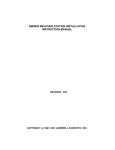
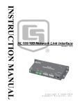
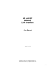
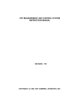
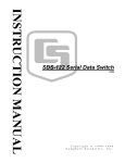
CR10X MEASUREMENT AND CONTROL MODULE
OPERATOR'S MANUAL
REVISION: 9/01
COPYRIGHT (c) 1986-2001 CAMPBELL SCIENTIFIC, INC.
This is a blank page.
CR10X MEASUREMENT AND CONTROL MODULE OVERVIEW
The CR10X is a fully programmable datalogger/controller with non-volatile memory and a battery backed
clock in a small, rugged, sealed module. The combination of reliability, versatility, and
telecommunications support make it a favorite choice for networks and single logger applications.
Campbell Scientific Inc. provides four aids to operating the CR10X:
1.
2.
3.
4.
PCTOUR
This Overview
The CR10X Operator's Manual
The CR10X Prompt Sheet
PCTOUR is a computer-guided tour of CR10X operation and the use of the PC208 Datalogger Support
Software. Much of the material in this Overview is covered in PCTOUR. A copy of PCTOUR is available
on our web site www.campbellsci.com.
This Overview introduces the concepts required to take advantage of the CR10X's capabilities. Handson programming examples start in Section OV5. Working with a CR10X will help the learning process,
so don't just read the examples, do them. If you want to start this minute, go ahead and try the
examples, then come back and read the rest of the Overview.
The sections of the Operator's Manual which should be read to complete a basic understanding of the
CR10X operation are the Programming Sections 1-3, the portions of the data retrieval Sections 4 and 5
appropriate to the method(s) you are using (see OV6), and Section 14 which covers installation and
maintenance.
Section 6 covers details of serial communications. Sections 7 and 8 contain programming examples.
Sections 9-12 have detailed descriptions of each programming instruction, and Section 13 goes into
detail on the CR10X measurement procedures.
The Prompt Sheet is an abbreviated description of the programming instructions. Once familiar with the
CR10X, it is possible to program it using only the Prompt Sheet as a reference, consulting the manual if
further detail is needed.
Read the Selected Operating Details and Cautionary Notes at the front of the Manual before using the
CR10X.
OV1. PHYSICAL DESCRIPTION
The CR10X was designed to provide a rugged
sealed datalogger with a low per unit cost.
Some of its distinguishing physical features are:
•
The CR10X does not have an integral
keyboard/display. The user accesses the
CR10X with the portable CR10KD
Keyboard Display or with a computer or
terminal (Section OV2).
•
The CR10X does not have an integral
terminal strip. A removable wiring panel
(Figure OV1.1-1) performs this function and
attaches to the two D-type connectors
located at the end of the module.
•
The power supply is external to the CR10X.
This gives the user a wide range of options
(Section 14) for powering the CR10X.
OV1.1 WIRING PANEL
The CR10X Wiring Panel and CR10X
datalogger make electrical contact through the
two D-type connectors at the (left) end of the
CR10X.
The Wiring Panel contains a 9-pin Serial I/O
port used when communicating with the
datalogger and provides terminals for
connecting sensor, control, and power leads to
the CR10X. It also provides transient protection
and reverse polarity protection. Figure OV1.1-2
shows the panel and the instructions used to
access the various terminals.
OV-1
CR10X OVERVIEW
CR10XTCR Thermocouple
Reference Thermistor
and Cover
,
N
A
G
O
L
H
A
T
U
E
S EF
D
G
8
H
7 4
G
L
0
1
H
9 5
G
A
E
S EF
D
L
2
1
H
G
L
2
H
1 1
1 6
1
G
G
A
H
T D
R N
A U
E O
R
C
G
A
L
3
E
G
A
G
A
4
H
3 2
G
L
G
6
H
5 3
G
A
L
G
G
A
G
G
L
R
T
C
V V
2
1 12
W W
S S
G
3
E
G
A
G
A
G
G
H
V
2
1 ER
G W
O
P IN
L
R
H
C
G
A
1
0
L
X
G
A
C
S
W
H
I/
0
M
A
P
G
I N USA
I R E IN
D
N
V
2
1
A
V
2
M 1
D 3
S E
G
A
L
E
L
G .
IN NO
IR L
W E
N
A
P
M
EA
SU
RE
firmM
E
w NT
are A
N
C DC
19 O
83 NT
, 1 RO
98 L
6, M
19 OD
95 U
LE
SERIAL i/O
CR
10
S/N
X
:X
10
12
CR10KD
KEYBOARD
DISPLAY
1
2
3
A
4
5
6
B
7
8
9
C
*
0
#
D
MADE IN
USA
FIGURE OV1.1-1. CR10X and Wiring Panel, CR10KD, and CR10XTCR
OV-2
ANALOG INPUTS
CR10X OVERVIEW
Input/Output Instructions
1 Volt (SE)
2 Volt (DIFF)
4 Ex-Del-Se
5 AC Half Br
6 Full Br
7 3W Half Br
8 Ex-Del-Diff
9 6W Full Br
11 Temp (107)
12 RH-(207)
13 Temp-TC SE
14 Temp-TC DIFF
16 Temp-RTD
27 Interval-Freq.
28 Vibrating Wire Meas
29 INW Press
131 Enhanced Vib. Wire
SERIAL I/O
Telecommunications
Program Control Instructions
96 Storage Module, Printer
97 Initiate Telecommunications
120 TGT1 GOES Satellite
121 ARGOS Satellite
122 INMARSAT-C Satellite
123 TGT1 Programming
Switched
12 Volts
12 Volt
Power Inputs
G 12V
Logan, Utah
SW 12V CTRL
SE
DIFF
7
8
9
4
G
G
H
10
5
L
AG H
L
11 12
6
AG H L AG E3
SW 12V
AG G
G
5V 5V G
G 12V
POWER
IN
CS I/O
G
CR10X WIRING PANEL
MADE IN USA
1
SE
DIFF
2
3
L
AG H
G
H
4
5
L
AG H
2
1
G
6
SDM
3
L
AG E1
AG E2 G
P1 G
P2 G C8 C7 C6 C5 C4 C3 C2 C1 G 12V 12V
EARTH
GROUND
WIRING
PANEL NO.
DIGITAL I/O PORTS
Earth Ground
Connect 12ga or larger
wire to earth ground
EXCITATION OUTPUTS
Input/Output Instructions
4
5
6
7
8
9
11
12
22
28
29
Ex-Del-Se
AC Half Br
Full Br
3W Half Br
Ex-Del-Diff
Full Br-Mex
Temp (107)
RH (207)
Excit-Del
Wire Meas
INW Press
PULSE INPUTS
Input/Output Instructions
3 Pulse
Input/Output Instructions
3 Pulse
15 Serial I/O
20 Set Ports
21 Pulse Port
25 Read Ports
100-110, 118 SDM and SDI12
Instructions
Program Control Instructions
83 If Case < F
86 Do
88 If X <=> Y
89 If X <=> F
91 If flag, port
92 If Time
Command Codes:
4X Set port x high
5X Set port x low
6X Toggle port x
7X Pulse port x
96 Port Subr.
97 Port Subr.
98 Port Subr.
FIGURE OV1.1-2. CR10X Wiring Panel/Programming Instructions
OV-3
CR10X OVERVIEW
OV1.1.1 ANALOG INPUTS
OV1.1.5 ANALOG GROUND (AG)
The terminals labeled 1H to 6L are analog
inputs. These numbers refer to the high and
low inputs to the differential channels 1 through
6. In a differential measurement, the voltage on
the H input is measured with respect to the
voltage on the L input. When making singleended measurements, either the H or L input
may be used as an independent channel to
measure voltage with respect to the CR10X
analog ground (AG). The single-ended
channels are numbered sequentially starting
with 1H; e.g., the H and L sides of differential
channel 1 are single-ended channels 1 and 2;
the H and L sides of differential channel 2 are
single-ended channels 3 and 4, etc. (The blue
single-ended channel numbers do NOT appear
on older wiring panels).
The AG terminals are analog grounds, used as
the reference for single-ended measurements
and excitation return.
OV1.1.2 EXCITATION OUTPUTS
The G terminals are also used to tie cable
shields to ground, and to provide a ground
reference for pulse counters and binary inputs.
The G terminals are directly connected to the
Earth terminal. For protection against transient
voltage spikes, Earth should be connected to a
good earth ground (Section 14.7.1).
The terminals labeled E1, E2, and E3 are
precision, switched excitation outputs used to
supply programmable excitation voltages for
resistive bridge measurements. DC or AC
excitation at voltages between -2500 mV and
+2500 mV are user programmable (Section 9).
OV1.1.6 12V, POWER GROUND (G), AND
EARTH TERMINALS
The 12V and power ground (G) terminals are
used to supply 12V DC power to the datalogger.
The extra 12V and G terminals can be used to
connect other devices requiring unregulated
12V power.
CAUTION: The CR10X does not regulate the
voltage to the 12 V terminals. The 12 V
terminals are connected directly to the 12 V
power in terminal. Any voltage regulation must
be done by the power supply (Section 14).
OV1.1.7 5V OUTPUTS
OV1.1.3 PULSE INPUTS
The terminals labeled P1 and P2 are the pulse
counter inputs for the CR10X. They are
programmable for high frequency pulse, low
level AC, or switch closure (Section 9,
Instruction 3).
OV1.1.4 DIGITAL I/O PORTS
Terminals C1 through C8 are digital
Input/Output ports. On power-up they are
configured as input ports, commonly used for
reading the status of an external signal. High
and low conditions are: 3V < high < 5.5V; -0.5V
< low < 0.8V.
Configured as outputs the ports allow on/off
control of external devices. A port can be set
high (5V ± 0.1V), set low (<0.1V), toggled or
pulsed (Sections 3, 8.3, and 12).
Ports C6 through C8 can be configured as
pulse counters for switch closures (Section 9,
Instruction 3) or used to trigger subroutine
execution (Section 1.1.2).
The two 5V (±0.2%) outputs are commonly
used to power peripherals such as the QD1
Incremental Encoder Interface, AVW1 or AVW4
Vibrating Wire Interface.
The 5V outputs are common with pin 1 on the 9
pin serial connector; 200 mA is the maximum
combined output.
OV1.1.8 SERIAL I/O
The 9 pin serial I/O port contains lines for serial
communication between the CR10X and
external devices such as computers, printers,
Storage Modules, etc. This port does NOT
have the same configuration as the 9 pin
serial ports currently used on many personal
computers. It has a 5VDC power line which is
used to power peripherals such as the Storage
Modules or the DC112 Phone Modem. The
same 5VDC supply is used for the 5V outputs on
the lower terminal strip. Section 6 contains
technical details on serial communication.
OV1.1.9 SWITCHED 12 VOLT
The switched 12 volt output can be used to
power sensors or devices requiring an
OV-4
CR10X OVERVIEW
unregulated 12 volts. The output is limited to
600 mA current.
A control port is used to operate the switch.
Connect a wire from the control port to the
switched 12 volt control port. When the port is
set high, the 12 volts is turned on; when the port
is low, the switched 12 volts is off (Section 8.12).
OV1.2 CONNECTING POWER TO THE CR10X
The CR10X can be powered by any 12VDC
source. The green power connector is a plug in
connector that allows the power supply to be
easily disconnected without unscrewing the
terminals. The Wiring Panel power connection
is reverse polarity protected. See Section 14 for
details on power supply connections.
CAUTION: The metal surfaces of the
CR10X Wiring Panel, and CR10KD
Keyboard Display are at the same potential
as power ground. To avoid shorting 12
volts to ground, connect the 12 volt lead
first, then connect the ground lead.
When primary power falls below 9.6 VDC for
one millisecond, the CR10X stops executing its
programs. The Low Voltage Counter (∗B
window 9) is incremented by one each time the
primary power falls below 9.6 VDC and E10 is
displayed on the CR10KD. A double dash (--) in
the 9th window of the ∗B mode indicates that
the CR10X is currently in a low primary power
mode. (Section 1.6)
The datalogger program and stored data remain
in memory, and the clock continues to keep
time when power is disconnected. The clock
and SRAM are powered by an internal lithium
battery.
OV2. MEMORY AND PROGRAMMING
CONCEPTS
OV2.1 INTERNAL MEMORY
The standard CR10X has 128 K of Flash
Electrically Erasable Programmable Read Only
Memory (EEPROM) and 128 K Static Random
Access Memory (SRAM). The Flash EEPROM
stores the operating system and user programs.
RAM is used for data and running the program.
Data Storage can be expanded with an optional
Flash EEPROM (Figure OV2.1-1). The use of
the Input, Intermediate, and Final Storage in the
measurement and data processing sequence is
shown in Figure OV2.1-2. The five areas of
SRAM are:
1. System Memory - used for overhead tasks
such as compiling programs, transferring
data, etc. The user cannot access this
memory.
2. Program Memory - available for user
entered programs.
3. Input Storage - Input Storage holds the
results of measurements or calculations.
The ∗6 Mode is used to view Input Storage
locations for checking current sensor
readings or calculated values. Input
Storage defaults to 28 locations. Additional
locations can be assigned using the ∗A
Mode.
4. Intermediate Storage - Certain Processing
Instructions and most of the Output
Processing Instructions maintain
intermediate results in Intermediate
Storage. Intermediate storage is
automatically accessed by the instructions
and cannot be accessed by the user. The
default allocation is 64 locations. The
number of locations can be changed using
the ∗A Mode.
5. Final Storage - Final processed values are
stored here for transfer to printer, solid state
Storage Module or for retrieval via
telecommunication links. Values are stored
in Final Storage only by the Output
Processing Instructions and only when the
Output Flag is set in the user’s program.
Approximately 62,000 locations are
allocated to Final Storage on power up.
This number is reduced if Input or
Intermediate Storage is increased.
While the total size of these three areas
remains constant, memory may be reallocated
between the areas to accommodate different
measurement and processing needs (∗A Mode,
Section 1.5).
OV-5
CR10X OVERVIEW
Flash Memory
(EEPROM)
Total 128 Kbytes
Operating System
(96 Kbytes)
How it works:
The Operating System is loaded into
Flash Memory at the factory. System
Memory is used while the CR10X is
running calculations, buffering data and
for general operating tasks.
Any time a user loads a program into
the CR10X, the program is compiled in
SRAM and stored in the Active
Program areas. If the CR10X is
powered off and then on, the Active
Program is loaded from Flash and run.
The Active Program is run in SRAM to
maximize speed. The program
accesses Input Storage and
Intermediate Storage and stores data
into Final Storage for later retrieval by
the user.
Active Program
(16 Kbytes)
Stored Programs
(16 Kbytes)
The Active Program can be copied into
the Stored Programs area. While 98
program "names" are available, the
number of programs stored is limited
by the available memory. Stored
programs can be retrieved to become
the active program. While programs
are stored one at a time, all stored
programs must be erased at once. That
is because the flash memory can only
be written to once before it must be
erased and can only be erased in 16
Kbytes blocks.
With the Optional Flash Memory, up to
2 Mbytes of additional memory can be
added to increase Final Storage by
another 524,288 data values per
Mbyte. The user can allocate this extra
memory to any combination of Area 1
or Area 2.
(Memory Areas separated by dashed
lines:
can be re-sized by the user.)
FIGURE OV2.1-1. CR10X Memory
OV-6
SRAM
Total 128 Kbytes
System Memory
(4096 Bytes)
Active Program
(default 2048 Bytes)
Input Storage
(default 28 locations,
112 bytes)
Intermediate Storage
(default 64 locations,
256 bytes)
Final Storage Area 1
(default 62,280
locations, 124,560
bytes)
Final Storage Area 2
(default 0 locations,
0 bytes)
Optional
Flash EEPROM
Final Storage Area 1
and/or
Final Storage Area 2
(Additional 524,288
locations per Mbyte)
CR10X OVERVIEW
OV2.2 PROGRAM TABLES, EXECUTION
INTERVAL AND OUTPUT INTERVALS
The CR10X must be programmed before it will
make any measurements. A program consists
of a group of instructions entered into a
program table. The program table is given an
execution interval which determines how
frequently that table is executed. When the
table is executed, the instructions are executed
in sequence from beginning to end. After
executing the table, the CR10X waits the
remainder of the execution interval and then
executes the table again starting at the
beginning.
The interval at which the table is executed
generally determines the interval at which the
sensors are measured. The interval at which
data are stored is separate from how often the
table is executed, and may range from samples
every execution interval to processed
summaries output hourly, daily, or on longer or
irregular intervals.
Table 1.
Execute every x sec.
0.0156 < x < 8191
Instructions are executed
sequentially in the order they
are entered in the table. One
complete pass through the
table is made each execution
interval unless program
control instructions are used
to loop or branch execution.
Normal Order:
MEASURE
PROCESS
CHECK OUTPUT COND.
OUTPUT PROCESSING
Programs are entered in Tables 1 and 2.
Subroutines, called from Tables 1 and 2, are
entered in Subroutine Table 3. The size of
program memory can be fixed or automatically
allocated by the CR10X (Section 1.5).
Table 1 and Table 2 have independent
execution intervals, entered in units of seconds
with an allowable range of 1/64 to 8191
seconds. Subroutine Table 3 has no execution
interval; subroutines are only executed when
called from Table 1 or 2.
OV2.2.1 THE EXECUTION INTERVAL
The execution interval specifies how often the
program in the table is executed, which is
usually determined by how often the sensors
are to be measured. Unless two different
measurement rates are needed, use only one
table. A program table is executed sequentially
starting with the first instruction in the table and
proceeding to the end of the table.
Table 2.
Execute every y sec.
0.0156 < y < 8191
Table 2 is used if there is a
need to measure and
process data on a separate
interval from that in Table 1.
Table 3.
Subroutines
A subroutine is executed
only when called from Table
1 or 2.
Subroutine Label
Instructions
End
Subroutine Label
Instructions
End
Subroutine Label
Instructions
End
FIGURE OV2.2-1. Program and Subroutine Tables
OV-7
CR10X OVERVIEW
Each instruction in the table requires a finite
time to execute. If the execution interval is less
than the time required to process the table, an
execution interval overrun occurs; the CR10X
finishes processing the table and waits for the
next execution interval before initiating the
table. When an overrun occurs, decimal points
are shown on either side of the G on the display
in the LOG mode (∗0). Overruns and table
priority are discussed in Section 1.1.
OV2.2.2. THE OUTPUT INTERVAL
The interval at which output occurs must be an
integer multiple of the execution interval (e.g., a
table cannot have a 10 minute execution
interval and output every 15 minutes).
A single program table can have many different
output intervals and conditions, each with a
unique data set (Output Array). Program
Control Instructions are used to set the Output
Flag. The Output Processing Instructions which
follow the instruction setting the Output Flag
determine the data output and its sequence.
Each additional Output Array is created by
another Program Control Instruction checking a
output condition, followed by Output Processing
Instructions defining the data set to output.
OV2.3 CR10X INSTRUCTION TYPES
Figure OV2.3-1 illustrates the use of three
different instruction types which act on data.
The fourth type, Program Control, is used to
control output times and vary program
execution. Instructions are identified by
numbers.
1. INPUT/OUTPUT INSTRUCTIONS (1-29,
100-110, 113-115, Section 9) control the
terminal strip inputs and outputs (Figure
OV1.1-2), storing the results in Input
Storage (destination). Multiplier and offset
parameters allow conversion of linear
signals into engineering units. The Digital
I/O Ports are also addressed with I/O
Instructions.
OV-8
2. PROCESSING INSTRUCTIONS (30-68,
Section 10) perform numerical operations
on values located in Input Storage and
store the results back in Input Storage.
These instructions can be used to develop
high level algorithms to process
measurements prior to Output Processing.
3. OUTPUT PROCESSING INSTRUCTIONS
(69-82, Section 11) are the only
instructions which store data in Final
Storage. Input Storage values are
processed over time to obtain averages,
maxima, minima, etc. There are two types
of processing done by Output Instructions:
Intermediate and Final.
Intermediate processing normally takes
place each time the instruction is executed.
For example, when the Average Instruction
is executed, it adds the values from the
input locations being averaged to running
totals in Intermediate Storage. It also keeps
track of the number of samples.
Final processing occurs only when the
Output Flag is high (Section 3.7.1). The
Output Processing Instructions check the
Output Flag. If the flag is high, final values
are calculated and output. With the
Average, the totals are divided by the
number of samples and the resulting
averages sent to Final Storage.
Intermediate locations are zeroed and the
process starts over. The Output Flag, Flag
0, is set high by a Program Control
Instruction which must precede the Output
Processing Instructions in the user entered
program.
4. PROGRAM CONTROL INSTRUCTIONS
(83-98, 111, 120-121, Section 12) are used
for logic decisions, conditional statements,
and to send data to peripherals. They can
set flags and ports, compare values or
times, execute loops, call subroutines,
conditionally execute portions of the
program, etc.
CR10X OVERVIEW
INPUT/OUTPUT
INSTRUCTIONS
Specify the conversion of a sensor signal
to a data value and store it in Input
Storage. Programmable entries specify:
(1) the measurement type
(2) the number of channels to measure
(3) the input voltage range
(4) the Input Storage Location
(5) the sensor calibration constants
used to convert the sensor output to
engineering units
I/O Instructions also control analog
outputs and digital control ports.
INPUT STORAGE
PROCESSING INSTRUCTIONS
Holds the results of measurements or
calculations in user specified locations.
The value in a location is written over
each time a new measurement or
calculation stores data to the locations.
Perform calculations with values in Input
Storage. Results are returned to Input
Storage. Arithmetic, transcendental and
polynomial functions are included.
OUTPUT PROCESSING
INSTRUCTIONS
INTERMEDIATE STORAGE
Perform calculations over time on the
values updated in Input Storage.
Summaries for Final Storage are
generated when a Program Control
Instruction sets the Output Flag in
response to time or events. Results
may be redirected to Input Storage for
further processing. Examples include
sums, averages, max/min, standard
deviation, histograms, etc.
Provides temporary storage for
intermediate calculations required by the
OUTPUT PROCESSING INSTRUCTIONS;
for example, sums, cross products,
comparative values, etc.
Output Flag set high
FINAL STORAGE
Final results from OUTPUT
PROCESSING INSTRUCTIONS are
stored here for on-line or interrogated
transfer to external devices (Figure
OV5.1-1). When memory is full, new
data overwrites the oldest data.
FIGURE OV2.3-1. Instruction Types and Storage Areas
OV-9
CR10X OVERVIEW
OV3. COMMUNICATING WITH CR10X
An external device must be connected to the
CR10X's Serial I/O port to communicate with
the CR10X. This may be either Campbell
Scientific's CR10KD Keyboard Display or a
computer/terminal.
The CR10KD is powered by the CR10X and
connects directly to the serial port via the SC12
cable (supplied with the CR10KD). No
interfacing software is required.
Computer communication and program editing
is accomplished using Campbell Scientific's
PC208 Datalogger Support Software. This
package contains a program editor (EDLOG),
datalogger communications, automated
telecommunications data retrieval, a data
reduction program, and programs to retrieve
data from Campbell Scientific Storage Modules.
To participate in the programming examples
(Section OV5) you must communicate with the
CR10X. Read Section OV3.1 if the CR10KD is
being used or Section OV3.2 if the PC208
software is being used.
OV3.1 CR10X KEYBOARD/DISPLAY
The SC12 cable (supplied with the CR10KD) is
used to connect the Keyboard/Display to the 9
pin Serial I/O port on the CR10X.
If the Keyboard/Display is connected to the
CR10X prior to being powered up, the "HELLO"
message is displayed while the CR10X checks
memory. The total size of memory is then
displayed (256 for 256 K bytes of memory).
When the CR10KD is plugged in after the
CR10X has powered up, the display is
meaningless until "∗" is pressed to enter a
mode.
This manual describes direct interaction with
the CR10X. If you have a CR10KD, work
through the direct programming examples in
this overview in addition to using EDLOG and
you will have the basics of CR10X operation as
well as an appreciation for the help provided by
the software.
OV-10
OV3.1.1 FUNCTIONAL MODES
CR10X/User interaction is broken into different
functional MODES (e.g., programming the
measurements and output, setting time,
manually initiating a block data transfer to
Storage Module, etc.). The modes are referred
to as Star (∗) Modes since they are accessed by
first keying ∗, then the mode number or letter.
Table OV3.1-1 lists the CR10X Modes.
TABLE OV3.1-1. ∗ Mode Summary
Key
∗
0
∗
1
∗
2
∗
3
∗
4
∗
5
∗
6
∗
7
∗
8
∗
9
∗
A
∗
B
∗
C
∗
D
∗
#
Mode
LOG data and indicate active Tables
Program Table 1
Program Table 2
Program Table 3, subroutines only
Parameter Entry Table
Display/set real time clock
Display/alter Input Storage data,
toggle flags or control ports.
Display Final Storage data
Final Storage data transfer to peripheral
Storage Module commands
Memory allocation/reset
Signature/status
Security
Save/load Program
Used with TGT1 satellite transmitter
OV3.1.2 KEY DEFINITION
Keys and key sequences have specific
functions when using the CR10KD keyboard or
a computer/terminal in the remote keyboard
state (Section 5). Table OV3.1-2 lists these
functions. In some cases, the exact action of a
key depends on the mode the CR10X is in and
is described with the mode in the manual.
CR10X OVERVIEW
TABLE OV3.1-2 Key Description/Editing
Functions
Key
0
Action
9
-
∗
A
B
C
D
#
#
A
#
B
#
D
#
0
Key numeric entries into display
Enter Mode (followed by Mode
Number)
Enter/Advance
Back up
Change the sign of a number or index
an input location to loop counter
Enter the decimal point
Clear the rightmost digit keyed into
the display
Advance to next instruction in
program table (∗1, ∗2, ∗3) or to next
Output Array in Final Storage (∗7)
Back up to previous instruction in
program table or to previous Output
Array in Final Storage
Delete entire instruction
(then A or CR) Back up to the start of
the current array.
When using a computer/terminal to communicate
with the CR10X (Telecommunications remote
keyboard state) there are some keys available in
addition to those found on the CR10KD. Table
OV3.1-3 lists these keys.
TABLE OV3.1-3. Additional Keys Allowed in
Telecommunications
Key
Action
CR
:
S or ^S
Change Sign, Index (same as C)
Enter/advance (same as A)
Colon (used in setting time)
Stops transmission of data (10
second time-out; any character
restarts)
Aborts transmission of Data
C or ^C
OV3.2 USING COMPUTER WITH DATALOGGER
SUPPORT SOFTWARE
Direct datalogger communication programs in
the datalogger support software (PC208E,
TCOM datalogger session) provide menu
selection of tools to perform the datalogger
functions (e.g., set clock, send program,
monitor measurements, and collect data). The
user also has the option of directly entering
keyboard commands via a built-in terminal
emulator (Section OV3.3).
When using the support software, the
computer’s baud rate, port, and modem types
are specified and stored in a file for future use.
The simplest and most common interface is the
SC32A Optically Isolated RS232 Interface. The
SC32A converts and optically isolates the
voltages passing between the CR10X and the
external terminal device.
The SC12 Two Peripheral cable which comes
with the SC32A is used to connect the serial I/O
port of the CR10X to the 9 pin port of the
SC32A labeled "Datalogger". Connect the
"Terminal/Printer" port of the SC32A to the
serial port of the computer with a straight 25 pin
cable or, if the computer has a 9 pin serial port,
a standard 9 to 25 pin adapter cable.
OV3.3 ASCII TERMINAL OR COMPUTER WITH
TERMINAL EMULATOR
Devices which can be used to communicate
with the CR10X include standard ASCII
terminals and computers programmed to
function as a terminal emulator. See Section
6.7 for details.
To communicate with any device other than the
CR10KD, the CR10X enters its Telecommunications Mode and responds only to valid
telecommunications commands. Within the
Telecommunications Mode, there are 2 "states";
the Telecommunications Command state and the
Remote Keyboard state. Communication is
established in the Telecommunications command
state. One of the commands is to enter the
Remote Keyboard state (Section 5).
The Remote Keyboard state allows the
keyboard of the computer/terminal to act like
the CR10KD keyboard. Various datalogger
modes may be entered, including the mode in
which programs may be keyed in to the CR10X
from the computer/terminal.
OV4. PROGRAMMING THE CR10X
A datalogger program is created on a computer
using EDLOG or one of the programming aids
such as Short Cut. A program can also be
entered directly into the datalogger. Section
OV4.3 describes options for loading the
program into the CR10X.
OV-11
CR10X OVERVIEW
OV4.1 PROGRAMMING SEQUENCE
In routine applications, the CR10X measures
sensor output signals, processes the
measurements over some time interval and
stores the processed results. A generalized
programming sequence is:
1. Enter the execution interval. In most cases,
the execution interval is determined by the
desired sensor scan rate.
2. Enter the Input/Output instructions required
to measure the sensors.
OV4.2 INSTRUCTION FORMAT
Instructions are identified by an instruction
number. Each instruction has a number of
parameters that give the CR10X the information
it needs to execute the instruction.
The CR10X Prompt Sheet has the instruction
numbers in red, with the parameters briefly
listed in columns following the description.
Some parameters are footnoted with further
description under the "Instruction Option Codes"
heading.
3. If processing in addition to that provided by
the Output Processing Instructions (step 5)
is required, enter the appropriate
Processing Instructions.
For example, Instruction 73 stores the
maximum value that occurred in an Input
Storage location over the output interval.
4. Enter the Program Control Instruction to
test the output condition and set the Output
Flag when the condition is met. For
example, use
P73 Maximum
1:
Reps
2:
TimeOption
3:
Loc
Instruction 92 to output based on time.
Instruction 86 to output every execution
interval.
Instruction 88 or 89 to output based on a
comparison of values in input locations.
This instruction must precede the Output
Processing Instructions which store data in
Final Storage. Instructions are described in
Sections 9 through 12.
5. Enter the Output Processing Instructions to
store processed data in Final Storage. The
order in which data are stored is determined
by the order of the Output Processing
Instructions in the table.
6. Repeat steps 4 and 5 for additional outputs
on different intervals or conditions.
NOTE: The program must be executed for
output to occur. Therefore, the interval at
which the Output Flag is set must be evenly
divisible by the execution interval. For
example, with a 2 minute execution interval
and a 5 minute output interval, the program
will only be executed on the even multiples
of the 5 minute intervals, not on the odd.
Data will be output every 10 minutes
instead of every 5 minutes.
Execution intervals and output intervals set with
Instruction 92 are synchronized with real time
starting at midnight.
OV-12
The instruction has three parameters (1)
REPetitionS, the number of sequential Input
Storage locations on which to find maxima, (2)
TIME, an option of storing the time of
occurrence with the maximum value, and (3)
LOC the first Input Storage location operated on
by the Maximum Instruction. The codes for the
TIME parameter are listed in the "Instruction
Option Codes".
The repetitions parameter specifies how many
times an instruction's function is to be repeated.
For example, four 107 thermistor probes may be
measured with a single Instruction 11, Temp107, with four repetitions. Parameter 2 specifies
the input channel of the first thermistor (the
probes must be connected to sequential
channels). Parameter 4 specifies the Input
Storage location in which to store measurements
from the first thermistor. If location 5 were used
and the first probe was on channel 1, the
temperature of the thermistor on channel 1
would be stored in input location 5, the
temperature from channel 2 in input location 6,
etc.
Detailed descriptions of the instructions are
given in Sections 9-12. Entering an instruction
into a program table is described in OV5.
CR10X OVERVIEW
OV4.3 ENTERING A PROGRAM
Programs are entered into the CR10X in one of
three ways:
1. Keyed in using the CR10X keyboard.
2. Loaded from a pre-recorded listing using
the ∗D Mode. There are 2 types of
storage/input:
a. Stored on disk/sent from computer.
b. Stored/loaded from Storage Module.
3. Loaded from internal Flash Memory or
Storage Module upon power-up.
A program is created by keying it directly into
the datalogger as described in Section OV5, or
on a PC using EDLOG or a programming aid
such as Short Cut.
Program files (.DLD) can be downloaded directly to
the CR10X using PC208E, GraphTerm, or TCOM.
Communication via direct wire, telephone, or Radio
Frequency (RF) is supported.
Programs on disk can be copied to a Storage
Module with the appropriate software. Using the
∗D Mode to save or load a program from a
Storage Module is described in Section 1.8.
Once a program is loaded in the CR10X, the
program will be stored in flash memory and will
automatically be loaded and run when the
datalogger is powered-up.
The program on power up function can also be
achieved by using a Storage Module. Up to 8
programs can be stored in the Storage Module,
the programs may be assigned any of the
numbers 1-8. If the Storage Module is
connected when the CR10X is powered-up the
CR10X will automatically load program number
8, provided that a program 8 is loaded in the
Storage Module (Section 1.8). The program
from the Storage Module will replace the active
program in flash memory.
OV5. PROGRAMMING EXAMPLES
The following examples stress direct interaction
with the CR10X using the CR10KD. At the
beginning of each example is an EDLOG listing
of the program. You can also participate in the
example by entering the program in EDLOG
and sending it to the CR10X and viewing
measurements with PC208E. (See PC Tour
and the PC208 manual for guidance.) If you
have the CR10KD, work through the examples
as well as using EDLOG. You will learn the
basics of CR10X operation as well as an
appreciation for the help provided by the
software.
We will start with a simple programming
example. There is a brief explanation of each
step to help you follow the logic. When the
example uses an instruction, find it on the
Prompt Sheet and follow through the description
of the parameters. Using the Prompt Sheet
while going through these examples will help
you become familiar with its format. Sections 912 have more detailed descriptions of the
instructions.
Connect the CR10X to the CR10KD
Keyboard/Display or a terminal (Section OV3).
With the Wiring Panel connected to the CR10X,
hook up the power leads as described in
Section OV1.2. The programming steps in the
following examples use the keystrokes possible
on the keyboard/display. With a terminal, some
responses will be slightly different.
If the CR10KD is connected to the CR10X when
it is powered up, the display will show:
Display
HELLO
Explanation
On power-up, the CR10X
displays "HELLO" while it
checks the memory (this
display occurs only with the
CR10KD).
after a few seconds delay
:0256
The size of the machine's total
memory, 256 K (1280 if 1 meg
option).
When primary power is applied to the CR10X, it
tests the FLASH memory and loads the current
program to RAM. After the program compiles
successfully, the CR10X begins executing the
OV-13
CR10X OVERVIEW
program. If the ring line on the 9 pin connector
is raised while the CR10X is testing memory,
there will be a 128 second delay before
compiling and running the program. This can
be used to edit or change the program before it
starts running. To raise the ring line, press any
key on the CR10KD keyboard display or call the
CR10X with the computer during the power up
sequence (i.e., while “HELLO” is displayed on
the CR10KD).
In order to ensure that there is no active
program in the CR10X, we will load an empty
program using the *D Mode:
Display Will Show:
Key (ID:Data)
Explanation
∗
00:00
Enter mode
D
13:00
Enter *D Mode
7
13:7
7 is command to load
program from flash
A
07:00
Execute command 7,
CR10X is ready for
program number
0
07:0
A
Indicating that the
command is complete.
OV5.1 SAMPLE PROGRAM 1
EDLOG Listing Program 1:
*Table 1 Program
01:
5.0
3: Sample (P70)
1:
1
2:
1
OV-14
∗
00:00
Enter mode.
1
01:0000
Enter Program Table 1.
A
01:0.0000
Advance to execution
interval (In seconds)
5
01:5
Key in an execution
interval of 5 seconds.
A
01:P00
Enter the 5 second
execution interval and
advance to the first program
instruction location.
01:P17
Key in Instruction 17
which directs the CR10X
to measure the internal
temperature in degrees
C. This is an
Input/Output Instruction.
A
01:0000
Enter Instruction 17 and
advance to the first
parameter.
1
01:1
The input location to
store the measurement,
location 1.
A
02:P00
Enter the location # and
advance to the second
program instruction.
1
7
The CR10X is now programmed to read the internal
temperature every 5 seconds and place the reading
in Input Storage Location 1. The program can be
compiled and the temperature displayed.
Execution Interval (seconds)
1: Internal Temperature (P17)
1:
1
Loc [ CR10XTemp ]
2: Do (P86)
1:
10
Display Will Show:
(ID:Data)
Explanation
Key
Load Program 0 (empty
program)
Execute program load,
after a short wait, the
display will show
13:0000
In this example the CR10X is programmed to
read its own internal temperature (using a built
in thermistor) every 5 seconds and to send the
results to Final Storage.
Display Will Show:
(ID:Data)
Explanation
Key
∗
0
LOG 1
Exit Table 1, enter ∗0
Mode, compile table and
begin logging.
∗
6
06:0000
Enter ∗6 Mode (to view
Input Storage).
01:21.234
Advance to first storage
location. Panel temp. is
21.234oC (display shows
actual temperature so
exact value will vary).
Set Output Flag High
Reps
Loc [ CR10XTemp ]
A
CR10X OVERVIEW
Storage location to
sample).
Wait a few seconds:
01:21.423
∗
2
8
1
A
6
A
1
0
A
7
A
0
01:0000
The CR10X has read the
sensor and stored the
result again. The internal
temp is now 21.423 oC.
The value is updated
every 5 seconds when
the table is executed. At
this point the CR10X is
measuring the
temperature every 5
seconds and sending the
value to Input Storage.
No data are being saved.
The next step is to have
the CR10X send each
reading to Final Storage.
(Remember, the Output
Flag must be set first.)
Exit ∗6 Mode. Enter
program table 1.
02:P00
Advance to 2nd
instruction location (this
is where we left off).
02:P86
This is the DO instruction
(a Program Control
Instruction).
1
02:1
Input Storage Location 1,
where the temperature is
stored.
A
04:P00
Enter 1 and advance to
fourth program
instruction.
∗
00:00
Exit Table 1.
0
LOG 1
Enter ∗0 Mode, compile
program, log data.
The CR10X is now programmed to measure the
internal temperature every 5 seconds and send
each reading to Final Storage. Values in Final
Storage can be viewed using the ∗7 Mode.
Display Will Show:
(ID:Data)
Explanation
Key
∗
07: 13.000
Enter ∗7 Mode. The
Data Storage Pointer
(DSP) is at Location 13
(in this example).
A
01: 0102
Advance to the first
value, the Output Array
ID. 102 indicates the
Output Flag was set by
the second instruction in
Program Table 1.
7
01:00
Enter 86 and advance to
the first parameter (which
will specify the command
to execute).
01:10
This command sets the
Output Flag. (Flag 0)
A
02: 21.23
Advance to the first
stored temperature.
03:P00
Enter 10 and advance to
third program instruction.
A
01: 0102
03:P70
The SAMPLE instruction.
It directs the CR10X to
take a reading from an
Input Storage location
and send it to Final
Storage (an Output
Processing Instruction).
Advance to the next
output array. Same
Output Array ID.
A
02: 21.42
Advance to 2nd stored
temp, 21.42 deg. C.
01:0000
Enter 70 and advance to
the first parameter
(repetitions).
1
01:1
There is only one input
location to sample;
repetitions = 1.
A
02:0000
Enter 1 and advance to
second parameter (Input
There are no date and time tags on the data.
They must be put there with Output Instruction
77. Instruction 77 is used in the next example.
If a terminal is used to communicate with the
CR10X, Telecommunications Commands
(Section 5) can be used to view entire Output
Arrays (in this case the ID and temperature) at
the same time.
OV-15
CR10X OVERVIEW
OV5.2 SAMPLE PROGRAM 2
EDLOG Listing Program 2:
*Table 1 Program
01:
5.0
Execution Interval (seconds)
1: Internal Temperature (P17)
1:
1
Loc [ CR10XTemp ]
2: Thermocouple Temp (DIFF) (P14)
1:
1
Reps
2:
1
± 2.5 mV Slow Range
3:
5
DIFF Channel
4:
1
Type T (Copper-Constantan)
5:
1
Ref Temp Loc [ CR10XTemp ]
6:
2
Loc [ TCTemp ]
7:
1.0
Mult
8:
0.0
Offset
3: If time is (P92)
1:
0
2:
60
3:
10
Minutes (Seconds --) into a
Interval (same units as above)
Set Output Flag High
4: Real Time (P77)
1:
110
Day,Hour/Minute
5: Average (P71)
1:
2
2:
1
Reps
Loc [ CR10XTemp ]
6: If time is (P92)
1:
0
2: 1440
3:
10
Minutes (Seconds --) into a
Interval (same units as above)
Set Output Flag High
7: Real Time (P77)
1:
110
Day,Hour/Minute
8: Maximize (P73)
1:
1
Reps
2:
10
Value with Hr-Min
3:
2
Loc [ TCTemp ]
9: Minimize (P74)
1:
1
2:
10
3:
2
10:
1:
OV-16
Reps
Value with Hr-Min
Loc [ TCTemp ]
Serial Out (P96)
71
SM192/SM716/CSM1
This second example is more representative of a
real-life data collection situation. Once again the
internal temperature is measured, but it is used
as a reference temperature for the differential
voltage measurement of a type T (copperconstantan) thermocouple; the CR10X should
have arrived with a short type T thermocouple
connected to differential channel 5.
When using a type T thermocouple, the copper
lead (blue) is connected to the high input of the
differential channel, and the constantan lead
(red) is connected to the low input.
A thermocouple produces a voltage that is
proportional to the difference in temperature
between the measurement and the reference
junctions.
To make a thermocouple (TC) temperature
measurement, the temperature of the reference
junction (in this example, the approximate panel
temperature) must be measured. The CR10X
takes the reference temperature, converts it to
the equivalent TC voltage relative to 0oC, adds
the measured TC voltage, and converts the
sum to temperature through a polynomial fit to
the TC output curve (Section 13.4).
The internal temperature of the CR10X is not a
suitable reference temperature for precision
thermocouple measurements. It is used here
for the purpose of training only. To make
thermocouple measurements with the CR10X,
purchase the Campbell Scientific Thermocouple
Reference, Model CR10TCR (Section 13.4) and
make the reference temperature measurement
with Instruction 11.
Instruction 14 directs the CR10X to make a
differential TC temperature measurement. The
first parameter in Instruction 14 is the number of
times to repeat the measurement. Enter 1,
because in this example there is only one
thermocouple. If there were more than 1 TC,
they could be wired to sequential channels, and
the number of thermocouples entered for
repetitions. The CR10X would automatically
advance through the channels sequentially and
measure all of the thermocouples.
Parameter 2 is the voltage range to use when
making the measurement. The output of a type
T thermocouple is approximately 40 microvolts
per degree C difference in temperature between
the two junctions. The ±2.5 mV scale will
CR10X OVERVIEW
provide a range of +2500/40 = +62.5 oC (i.e.,
this scale will not overrange as long as the
measuring junction is within 62.5 oC of the
panel temperature). The resolution of the ±2.5
mV range is 0.33 µV or 0.008 oC.
Parameter 3 is the analog input channel on
which to make the first, and in this case only,
measurement.
Parameter 4 is the code for the type of
thermocouple used. This information is located
on the Prompt Sheet or in the description of
Instruction 14 in Section 9. The code for a type
T (copper-constantan) thermocouple is 1.
Parameter 5 is the Input Storage location in
which the reference temperature is stored.
Parameter 6 is the Input Storage location in
which to store the measurement (or the first
measurement; e.g., if there are 5 repetitions
and the first measurement is stored in location
3, the final measurement will be stored in
location 7). Parameters 7 and 8 are the
multiplier and offset. A multiplier of 1 and an
offset of 0 outputs the reading in degrees C. A
multiplier of 1.8 and an offset of 32 converts the
reading to degrees F.
In this example, the sensor is measured once a
minute, and the day, time, and average
temperature are output every hour. Once a day
the day, time, maximum and minimum
temperatures and the times they occur will be
output.
Final Storage data will be sent to Storage
Module. Remember, all on-line data output to a
peripheral device is accomplished with
Instruction 96 (Sections 4.1 and 12).
The first example described program entry one
keystroke at a time. This example does not
show the "A" key. Remember, "A" is used to
enter and/or advance (i.e., between each line in
the example below). This format is similar to
the format used in EDLOG.
example. You can find the program instructions
and parameters on the Prompt Sheet and can
read their complete definitions in the manual.
To obtain daily output, the If Time instruction is
again used to set the Output Flag and is
followed by the Output Instructions to store time
and the daily maximum and minimum
temperatures and the time each occurs.
Any Program Control Instruction which is used
to set the Output Flag high will set it low if the
conditions are not met for setting it high.
Instruction 92 in sample program 2 sets the
Output Flag high every hour. The Output
Instructions which follow the second Instruction
92 do not output every hour because the
second Instruction 92 sets the Output Flag high
at midnight (and sets it low at any other time).
This is a unique feature of Flag 0. The Output
Flag is set low at the start of each table (Section
3.7).
OV5.3 EDITING AN EXISTING PROGRAM
When editing an existing program in the
CR10X, entering a new instruction inserts the
instruction; entering a new parameter replaces
the previous value.
To insert an instruction, enter the program table
and advance to the position where the
instruction is to be inserted (i.e., P in the data
portion of the display) key in the instruction
number, and then key A. The new instruction
will be inserted at that point in the table,
advance through and enter the parameters.
The instruction that was at that point and all
instructions following it will be pushed down to
follow the inserted instruction.
An instruction is deleted by advancing to the
instruction number (P in display) and keying #D
(Table 4.2-1).
To change the value entered for a parameter,
advance to the parameter and key in the correct
value then press A. Note that the new value is
not entered until A is keyed.
It's a good idea to have both the manual and the
Prompt Sheet handy when going through this
OV-17
CR10X OVERVIEW
SAMPLE PROGRAM 2
Instruction #
(Loc:Entry)
Parameter
(Par#:Entry)
Description
∗1
Enter Program Table 1
01:60
60 second (1 minute) execution interval
Key # D until
is displayed
01:P00
01:P17
01:1
02:P14
(differential)
Erase previous Program before
continuing.
Measure internal temperature
Store temp in Location 1
Measure thermocouple temperature
01:1
02:1
03:5
04:1
05:1
06:2
07:1
08:0
1 repetition
Range code (2.5 mV, slow)
Input channel of TC
TC type: copper-constantan
Reference temp is stored in Location 1
Store TC temp in Location 2
Multiplier of 1
No offset
01:0
02:60
03:10
If Time instruction
0 minutes into the interval
60 minute interval
Set Output Flag 0
03:P92
The CR10X is programmed to measure the thermocouple temperature every sixty seconds.
The If Time instruction sets the Output Flag at the beginning of every hour. Next, the Output
Instructions for time and average are added.
Instruction #
(Loc.:Entry)
Parameter
(Par.#:Entry)
04:P77
01:110
05:P71
01:1
02:2
06:P92
Output Time instruction
Store Julian day, hour, and minute
Average instruction
one repetition
Location 2 - source of TC temps. to be
averaged
01:0
02:1440
03:10
If Time instruction
0 minutes into the interval
1440 minute interval (24 hrs.)
Set Output Flag 0
01:100
Output Time instruction
Store Julian day
01:1
02:10
03:2
Maximize instruction
One repetition
Output time of daily maximum in hours and minutes
Data source is Input Storage Location 2.
07: P77
08: P73
OV-18
Description
CR10X OVERVIEW
09: P74
01:1
02:10
03:2
Minimize instruction
One repetition
Output the time of the daily minimum in hours
and minutes
Data source is Input Storage Location 2.
The program to make the measurements and to send the desired data to Final Storage has
been entered. At this point, Instruction 96 is entered to enable data transfer from Final Storage
to Storage Module.
10:P96
1:71
Activate Serial Data Output.
Output Final Storage data to Storage Module.
The program is complete. (Here the example reverts back to the key by key format.)
Key
∗
5
A
1
9
9
6
A
1
9
7
A
1
3
A
∗
0
2
4
Display
Explanation
00:21:32
Enter ∗5 Mode. Clock running but perhaps not set correctly.
05:0000
Advance to location for year.
05:1996
Key in year (1996).
05:0000
Enter and advance to location for Julian day.
05:197
Key in Julian day.
05:0021
Enter and advance to location for hours and minutes (24 hr. time).
05:1324
Key in hrs.:min. (1:24 PM in this example).
:13:24:01
Clock set and running.
LOG 1
Exit ∗5, compile Table 1, commence logging data.
OV-19
CR10X OVERVIEW
OV6. DATA RETRIEVAL OPTIONS
There are several options for data storage and
retrieval. These options are covered in detail in
Sections 2, 4, and 5. Figure OV6.1-1
summarizes the various possible methods.
Regardless of the method used, there are three
general approaches to retrieving data from a
datalogger.
1) On-line output of Final Storage data to a
peripheral storage device. On a regular
schedule, that storage device is either
"milked" of its data or is brought back to the
office/lab where the data is transferred to
the computer. In the latter case, a "fresh"
storage device is usually left in the field
when the full one is taken so that data
collection can continue uninterrupted.
3) Retrieve the data over some form of
telecommunications link, whether it be RF,
telephone, short haul modem, or satellite.
This can be performed under program
control or by regularly scheduled polling of
the dataloggers. Campbell Scientific's
Datalogger Support Software automates
this process.
Regardless of which method is used, the
retrieval of data from the datalogger does NOT
erase those data from Final Storage. The data
remain in the ring memory until:
They are written over by new data (Section 2.1)
Memory is reallocated or the CR10X is reset
(Section 1.5)
Table OV6.1-1 lists the instructions used with
the various methods of data retrieval.
2) Bring a storage device to the datalogger
and milk all the data that has accumulated
in Final Storage since the last visit.
TABLE OV6.1-1. Data Retrieval Methods and Related Instructions
Method
Storage Module
Telecommunications
Printer or other
Serial device
OV-20
Instruction/Mode
Section in Manual
Instruction 96
∗8
∗9
Telecommunications
Commands
Instruction 97
Instruction 99
Instruction 96
Instruction 98
∗8
4.1, 12
4.2
4.5
5
12
12
4.1, 12
12
4.2
CR10X OVERVIEW
DATALOGGER
SC12 CABLES
DSP4
HEADS UP
DISPLAY
CSM1
SM192/716
STORAGE
MODULES
STORAGE
MODULE
OR CARD
BROUGHT
FROM THE
FIELD TO
THE
COMPUTER
MD9
MULTIDROP
INTERFACE
RF100/RF200
TRANSCEIVER
W/ ANTENNA
& CABLE
COAXIAL
CABLE
CSM1
SM192/716
STORAGE
MODULES
RF95 RF
MODEM
MD9
MULTIDROP
INTERFACE
RF100/RF200
TRANSCEIVER
W/ ANTENNA &
CABLE
SC12 CABLE
SC532
RS-232
INTERFACE
COMPUTER
SC932
INTERFACE
DC112
PHONE
MODEM
DC1765
CELLULAR
PHONE
SRM-6A RAD
SHORTHAUL
MODEM
SC32A
RS-232
INTERFACE
2 TWISTED
PAIR WIRES
UP TO 5 MI.
PHONE
LINE
SC12 CABLE
RF232 RF
BASE
STATION
SRM-6A RAD
SHORTHAUL
MODEM
HAYES
COMPATIBLE
PHONE
MODEM
RS-232
CABLE
ASYNCHRONOUS SERIAL
COMMUNICATIONS PORT
NOTES:
1. ADDITIONAL METHODS OF DATA RETRIEVAL ARE:
A. SATELLITE TRANSMISSION
B. DIRECT DUMP TO PRINTER
C. VOICE PHONE MODEM TO VOICE PHONE OR PC WITH HAYES COMPATIBLE
PHONE MODEM
2. THE DSP4 HEADS UP DISPLAY ALLOWS THE USER TO VIEW DATA IN INPUT
STORAGE. ALSO BUFFERS FINAL STORAGE DATA AND WRITES IT TO
CASSETTE TAPE, PRINTER OR STORAGE MODULE.
3. ALL CAMPBELL SCIENTIFIC RS-232 INTERFACES HAVE A FEMALE 25 PIN RS-232
CONNECTOR.
FIGURE OV6.1-1. Data Retrieval Hardware Options
OV-21
CR10X OVERVIEW
OV7. SPECIFICATIONS
Electrical specifications are valid over a -25° to +50°C range unless otherwise specified; non-condensing environment
required. To maintain electrical specifications, yearly calibrations are recommended.
PROGRAM EXECUTION RATE
PERIOD AVERAGING MEASUREMENTS
CR10XTCR THERMOCOUPLE REFERENCE
Program is synchronized with real-time up to 64 Hz.
One measurement with data transfer is possible at
this rate without interruption. Burst measurements up
to 750 Hz are possible over short intervals.
DEFINITION: The average period for a single cycle is
determined by measuring the duration of a specified number of cycles. Any of the 12 single-ended
analog input channels can be used. Signal attentuation and AC coupling are typically required.
POLYNOMIAL LINEARIZATION ERROR: Typically
<±0.5°C (-35° to +50°C), <±0.1°C (-24° to +45°C).
INPUT FREQUENCY RANGE:
EMI and ESD PROTECTION
ANALOG INPUTS
NUMBER OF CHANNELS: 6 differential or 12 singleended, individually configured. Channel expansion
provided by AM16/32 or AM416 Relay Multiplexers and AM25T Thermocouple Multiplexers.
ACCURACY: ±0.1% of FSR (-25° to 50°C);
±0.05% of FSR (0° to 40°C);
e.g., ±0.1% FSR = ±5.0 mV for ±2500
mV range
RANGE AND RESOLUTION:
Full Scale
Input Range (mV)
±2500
±250
±25
±7.5
±2.5
Resolution (µV)
Differential Single-Ended
333
666
33.3
66.6
3.33
6.66
1.00
2.00
0.33
0.66
INPUT SAMPLE RATES: Includes the measurement
time and conversion to engineering units. The
fast and slow measurements integrate the signal
for 0.25 and 2.72 ms, respectively. Differential
measurements incorporate two integrations with
reversed input polarities to reduce thermal offset
and common mode errors.
Fast single-ended voltage:
2.6 ms
Fast differential voltage:
4.2 ms
Slow single-ended voltage:
5.1 ms
Slow differential voltage:
9.2 ms
Differential with 60 Hz rejection: 25.9 ms
Fast differential thermocouple:
8.6 ms
INPUT NOISE VOLTAGE (for ±2.5 mV range):
Fast differential: 0.82 µV rms
Slow differential: 0.25 µV rms
Differential with 60 Hz rejection: 0.18 µV RMS
COMMON MODE RANGE: ±2.5 V
DC COMMON MODE REJECTION: >140 dB
NORMAL MODE REJECTION: 70 dB (60 Hz with
slow differential measurement)
INPUT CURRENT: ±9 nA maximum
INPUT RESISTANCE: 20 Gohms typical
ANALOG OUTPUTS
DESCRIPTION: 3 switched, active only during measurement, one at a time.
Signal peak-to-peak1
Min.
Max.
500
10
5
2
mV
mV
mV
mV
5.0 V
2.0 V
2.0 V
2.0 V
Min.
Pulse w.
2.5 µs
10 µs
62 µs
100 µs
ACCURACY: ±0.03% of reading
TIME REQUIRED FOR MEASUREMENT: Signal
period times the number of cycles measured plus
1.5 cycles + 2 ms
PULSE COUNTERS
NUMBER OF PULSE COUNTER CHANNELS: 2
eight-bit or 1 sixteen-bit; software selectable as
switch closure, high frequency pulse, and low
level AC.
MAXIMUM COUNT RATE: 16 kHz, eight-bit counter;
400 kHz, sixteen-bit counter. Channels are
scanned at 8 or 64 Hz (software selectable).
SWITCH CLOSURE MODE
Minimum Switch Closed Time: 5 ms
Minimum Switch Open Time: 6 ms
Maximum Bounce Time: 1 ms open without
being counted
HIGH FREQUENCY PULSE MODE
Minimum Pulse Width: 1.2 µs
Maximum Input Frequency: 400 kHz
Voltage Thresholds: Count upon transition
from below 1.5 V to above 3.5 V at low frequencies. Larger input transitions are required at high
frequencies because of input filter with 1.2 µs time
constant. Signals up to 400 kHz will be counted if
centered around +2.5 V with deviations ‡ – 2.5 V
for ‡ 1.2 µs.
Maximum Input Voltage: ±20 V
LOW LEVEL AC MODE
(Typical of magnetic pulse flow transducers or
other low voltage, sine wave outputs.)
Input Hysteresis: 14 mV
Maximum AC Input Voltage: ±20 V
Minimum AC Input Voltage:
(Sine wave mV RMS)
20
200
1000
CURRENT SINKING: 25 mA
kHz
kHz
kHz
kHz
RESOLUTION: 35 ns divided by the number of
cycles measured
RESOLUTION: 0.67 mV
CURRENT SOURCING: 25 mA
200
50
8
5
1Signals centered around datalogger ground
2Assuming 50% duty cycle
RANGE: ±2.5 V
ACCURACY: ±5 mV; ±2.5 mV (0° to 40°C);
Max
Freq.2
Range (Hz)
1.0 to 1000
0.5 to 10,000
0.3 to 16,000
FREQUENCY SWEEP FUNCTION: The switched
outputs provide a programmable swept frequency,
0 to 2.5 V square wave for exciting vibrating wire
transducers.
DIGITAL I/O PORTS
RESISTANCE MEASUREMENTS
OUTPUT VOLTAGES (no load): high 5.0 V ±0.1 V;
low < 0.1 V
MEASUREMENT TYPES: The CR10X provides
ratiometric bridge measurements of 4- and 6-wire
full bridge, and 2-, 3-, and 4-wire half bridges.
Precise dual polarity excitation using any of the
switched outputs eliminates dc errors.
Conductivity measurements use a dual polarity
0.75 ms excitation to minimize polarization errors.
ACCURACY: ±0.02% of FSR plus bridge resistor
error.
8 ports, software selectable as binary inputs or
control outputs. 3 ports can be configured to count
switch closures up to 40 Hz.
OUTPUT RESISTANCE: 500 ohms
INPUT STATE: high 3.0 to 5.5 V; low -0.5 to 0.8 V
INTERCHANGEABILITY ERROR: Typically <±0.2°C
(0° to +60°C) increasing to ±0.4°C (at -35°C).
EMISSIONS: Meets or exceeds following standards:
Radiated: per EN 55022:1987 Class B
Conducted: per EN 55022:1987 Class B
IMMUNITY: Meets or exceeds following standards:
ESD: per IEC 801-2;1984 8 kV air discharge
RF: per IEC 801-3;1984 3 V/m, 27-500 MHz
EFT: per IEC 801-4;1988 1 kV mains, 500 V
other
CE COMPLIANCE (as of 01/98)
APPLICATION OF COUNCIL DIRECTIVE(S):
89/336/EEC as amended by 89/336/EEC and
93/68/EEC
STANDARD(S) TO WHICH CONFORMITY IS
DECLARED:
ENC55022-1: 1995 and ENC50082-1: 1992
CPU AND INTERFACE
PROCESSOR: Hitachi 6303
PROGRAM STORAGE: Up to 16 kbytes for active
program; additional 16 kbytes for alternate
programs. Operating system stored in 128 kbytes
Flash memory.
DATA STORAGE: 128 kbytes SRAM standard
(approximately 60,000 data values). Additional
2 Mbytes Flash available as an option.
OPTIONAL KEYBOARD DISPLAY: 8-digit LCD
(0.5" digits)
PERIPHERAL INTERFACE: 9 pin D-type connector
for keyboard display, storage module, modem,
printer, card storage module, and RS-232
adapter.
BAUD RATES: Selectable at 300, 1200, 9600
and 76,800 for synchronous devices. ASCII communication protocol is one start bit, one stop bit,
eight data bits (no parity).
CLOCK ACCURACY: ±1 minute per month
SYSTEM POWER REQUIREMENTS
VOLTAGE: 9.6 to 16 Vdc
TYPICAL CURRENT DRAIN: 1.3 mA quiescent,
13 mA during processing, and 46 mA during
analog measurement.
BATTERIES: Any 12 V battery can be connected as
a primary power source. Several power supply
options are available from Campbell Scientific.
The Model CR2430 lithium battery for clock and
SRAM backup has a capacity of 270 mAhr.
PHYSICAL SPECIFICATIONS
SIZE: 7.8" x 3.5" x 1.5" - Measurement & Control
Module; 9" x 3.5" x 2.9" - with CR10WP Wiring
Panel. Additional clearance required for serial
cable and sensor leads.
WEIGHT: 2 lbs
WARRANTY
Three years against defects in materials and
workmanship.
INPUT RESISTANCE: 100 kohms
SDI-12 INTERFACE STANDARD
DESCRIPTION: Digital I/O Ports C1-C8 support
SDI-12 asynchronous communication; up to ten
SDI-12 sensors can be connected to each port.
Meets SDI-12 Standard version 1.2 for datalogger
and sensor modes.
We recommend that you confirm system
configuration and critical specifications with
Campbell Scientific before purchase.
Copyright © 1986, 2001
Campbell Scientific, Inc.
Printed September 2001
OV-22