1
CARROLL TOUCH
Chapter 1 - Introduction to Infrared Touch Systems
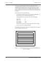
grid of IR beams in front of the video display surface. This grid of IR
beams is the touch active area.
When a stylus enters the touch active area, light beams are obstructed at
a particular location on the grid. The touch frame then transmits to the
controller a list that indicates which beams have been interrupted. The
controller converts this list into an x, y coordinate that identifies the
location of the touch. The x, y coordinate data is transmitted to the host
processor via the PC bus or the RS-232 serial port and is then processed
and used by the application program.
Interpolating Touch Coordinates
To achieve finer resolution than the physical IR beam grid provides,
Carroll Touch IR touch systems interpolate a virtual beam between each
pair of physical beams. The physical beams are assigned even numbers
(0, 2, 4, and so on). The virtual beams are assigned odd numbers (1, 3,
5, and so on). The combination of physical beams and virtual beams
results in a set of logical beams.
The coordinate system formed by the logical beams is called the logical
coordinate system. The origin of the logical coordinate system (0, 0) is
located in the upper left corner of the display. When multiple beams are
interrupted, the touch system averages them and reports one x, y logical
coordinate pair to the host, a process known as beam averaging.
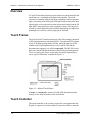
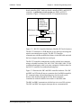
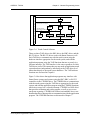
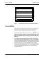
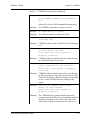
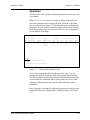
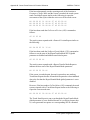
Examples of beam averaging are shown in Figures 1-2 and 1-3.
00
02
04
06
08
10
00
02
4,4
04
06
08
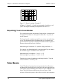
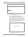
Figure 1-2. Beam Averaging - Example 1
In Figure 1-2, beams 2, 4, and 6 are interrupted on both the x- and
y-axes. The logical coordinate pair reported to the host is 4, 4.
Touch System Programmer’s Guide
1-3