1
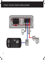
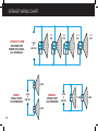
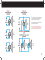
CSA SERIES AMPLIFIER // OWNERS MANUAL
FEATURES
INTRODUCTION
Thank you for purchasing this Cadence Momentum CSA Series amplifier. Over the years, the technology used to create
audio amplifiers has grown by leaps and bounds. We have tens of thousands of satisfied customers still using our first
generation Ultra Drive amplifiers which are more than 19 years old. Our competition is satisfied with just continuing to build
the same units year after year without thought for improvement, but not Cadence. We consider it our mission to use our
expertise in developing the latest technologies and to bring you the absolute best sounding, most powerful amplifiers on
the market and of course at a reasonable price. You will be amazed at the quality and power that these new amps offer.
You will “Boom-Harder!” with Momentum CSA Series amplifiers.
We have spared no expense in designing these amplifiers, creating the most rugged, reliable, powerful and best performing
amplifiers. In fact we are so sure of the quality we backup every Momentum amplifier with our exclusive two-year warranty
which exemplifies our commitment to excellence in car audio musical reproduction. (See enclosed warranty card for details.)
Please read this installation guide carefully for proper use of your Cadence amplifier. Should you need technical assistance
during or after your installation please call our technical line M - Th between 9:30 am and 5:00 PM EST at (732) 370-5400.
Read this entire guide fully before attempting your installation.
WARNING: BE AWARE! Use of this amplifier at extreme high volumes for extended periods of time may cause hearing loss
and or hearing damage. During periods of prolonged high volume levels it is recommended that you use ear safety devices.
Playing Cadence amplifiers at high volume levels while driving will impair your ability to hear necessary traffic sounds. While
driving always keep your sound volume at reasonable levels. We at Cadence want you listening for many years to come.
When installing the amplifier, secure it tightly. An unmounted amplifier in your car can cause serious injury to passengers and
damage to your vehicle if it is set in motion by an abrupt driving maneuver or short stop.
2
INSTALLATION
BATTERY VOLTAGE:
INSTALLATION BASICS:
Cadence Momentum CSA amplifiers are rated and regulated to 14.4 volts and below.
Maximum input voltage is 16 volts while the minimum voltage is 12 volts.
Before you begin with your installation, disconnect the NEGATIVE (-) terminal from
your car’s battery. This safety precaution will avoid possible short circuits while wiring
your amplifier. Cadence amplifiers operate on 12-volt negative ground systems only.
*** DO NOT EXCEED 16 INPUT VOLTAGE. ***
PROTECTION CIRCUITRY:
Cadence amplifiers incorporate many outstanding protection circuits to help protect the
amplifier from being damaged during operating conditions. Thermal Protection: When the amplifier reaches an unsafe operating temperature of 80
degrees Celsius the amplifier will turn off. Once the amplifier cools down, simply reset
the amplifier by its Remote connection, (turn the amplifier off and then on again once
you have given the amplifier a chance to cool down) and the amp will once again begin
to play.
If you live in a hot climate we suggest installing additional cooling fans in your trunk to
exhaust the hot air which can build up in the trunk this will help keep the ambient temperature
in the trunk as low as possible so that your amps work flawlessly and without any
musical interruption.
Clipping or total shutdown may also be a result of a bad ground connection or loose
ground. If you find that your speakers and speaker wires are not shorted, please check
your ground connection.
Input Overload Protection: This circuit will either shutdown the amplifier completely or
make the amplifier spurt on and off indicating that it is in a diagnostic condition. Turn
the system off and reduce the gain on the amplifier or volume from your head unit, this
should result in a corrected condition.
DC Offset Protection: Should any DC voltage try to enter the amplifier via the speaker
terminals it will cause the amplifier to shut down and not operate until this condition is
remedied. This circuit will also protect damaging high DC voltages from reaching your
speakers should your amplifier ever malfunction.
3
2
It is recommend that you layout your sound system design on paper first. This will help
you during the installation so that you will have a wiring flow chart and not miss-wire any
of your components.
Mount the amplifier in the trunk or hatch area of your vehicle. Never install an amplifier
in the engine compartment or on the fire wall. Please be sure to leave breathing room
around the amplifier heat sink so that it can dissipate the heat it produces efficiently.
The amplifier can be installed either horizontally or vertically.
When mounting the amplifier on the trunk floor, be sure to watch for your gas tank,
gas lines and electrical lines. Do not drill or mount any screws where they might
penetrate the gas tank of your car.
REMOTE TURN ON CONNECTION:
The remote turn on connection is located on the barrier strip next to the power and
ground connections. This connection is responsible for turning the amplifier on
and off with the rest of the system. A smaller gauge wire can be used to make this
connection to your radio’s power antenna lead. Should your system not have any
turn on leads, you can wire the remote terminal to an accessory lead, which turns on,
with your cars ignition.
POWER/GROUND WIRING:
The Momentum CSA series amplifiers are supplied with built-in fuses, never replace
the fuse that the amp came with, with one of a larger value.
We suggest you construct a Red wiring harness with 2 additional fuses. One fuse
should be located near the car battery. This fuse near the battery offers protection
against damage from short circuits to the car chassis between the battery and the
amplifier. A second fuse closer to the amplifier offers additional safety to the amplifier
itself. This fused red power wire should be attached to the amplifier power terminal
marked +12V.
FEATURES
The wire harness should be made of red primary cable of at least 8 gauge for the
CSA1000.2 and at least 4 gauge for all other larger models. The harness should
terminate in a large ring terminal for connection directly to the positive terminal of
the car battery. Use a spade plug to attach the wire, which connects to the amplifier
location marked +12V.
A second black color wire of equal gauge should be used as a ground connection to a
welded chassis member. When connecting the ground wire make sure that there is no
paint or other insulator blocking a good ground connection. When installing multiple
amplifiers, mount them in close proximity so that they can all share the same ground
point. Attach the black ground wire to the amplifier screw terminal marked Ground.
We recommend that you use the Cadence AMPKIT4 or AMPKIT8 amplifier installation
kits, which contains all the cabling and accessories necessary for a good, reliable
installation.
Over the years we have received amplifiers back to our service department with melted
power/ground terminals. The cause of this is a bad ground connection. When there is
a lack of good ground, heat builds up at the weakest point which happens to be the
contact screw of the amplifier terminal. Over time the heat generated will begin to melt
the terminal. It is a good practice to feel the power and ground wires with your hands,
near their amplifier connection after having played the amp for a while. If the wires feel
hot to the touch you probably have a bad or loose connection. If you are sure of your
connections and the wires still feel hot to the touch, you should upgrade the gauge of
wire to next heaviest gauge (see wiring diagram, page 5).
SETTING THE CONTROLS:
AUDIO PREAMP INPUT
The Momentum CSA series amplifiers feature RCA pre amp inputs. Run RCA cables
from your sound source to the inputs of the amplifier. We suggest the use of high
quality shielded RCA patch cords to help reduce and eliminate unwanted electrical
noise to your system. Be sure to run the RCA cables on the opposite side of the vehicle
that you used to carry the power and ground leads of the amplifier.
BUILT IN LOW PASS ELECTRONIC FILTER
All Momentum CSA series amplifiers feature 12dB per octave fully adjustable low-pass
and high pass electronic filters.
For Low Pass sub woofer systems, set the FILTER switch to LOW PASS. Now the knob
marked LPF or LOW PASS will control the low pass frequencies anywhere from 50Hz to
500Hz depending on the model. A frequent error made is setting the low pass frequency
too low, especially when using a vented sub woofer enclosures. We recommend that
for most installations you do not set the frequency knob lower than 80 to 100Hz (the
12 o’clock position).
When using the amplifiers for component speakers or co-axials, you will want to set the
FILTER switch to HIGH PASS. The HPF control knob adjusts the high pass frequencies
between 120Hz and 3KHz. Do not attach tweeters directly to the amplifier, (even in the
high pass mode) without a passive crossover to protect them.
SUBSONIC FILTERING
For sub woofer installations with passive LP crossover, you can set the amplifier’s
FILTER switch to HIGH PASS while setting the SUB SONIC knob to 30Hz, this will
act as SUBSONIC FILTER for all signals below 30Hz. This is especially useful for
vented enclosures where the port tuning frequency falls below the sub woofer tuning
frequency to protect against sub woofer unloading.
GAIN (INPUT LEVEL CONTROL)
To adjust the GAIN turn the control using a small flat head screwdriver fully counter
clock wise to the minimum position. Do not apply any pressure while turning as this
might break the control unit. Adjust your radio volume level to maximum volume. Now
turn the level control on the amplifier clockwise towards the Maximum marking until
audible distortion occurs. When you begin to hear any distortion in the sound, back
down one notch and your amp is set. It is helpful to have a second person to help you
set the gain.
When setting up a multi-amp system, set each amplifier’s gain separately. Start off with
the bass amplifier, then adjust the highs amplifier’s level control to match.
Once you are satisfied with the level control settings, use any equalizer controls to
adjust the system tonal level for personal preference. Keep in mind that after equalizing,
you may have to go back and reset the amplifiers level controls.
The level control of any car amplifier should not be mistaken for a volume control. It is a sophisticated device designed to match the output level of your
*source
unit to the input level of the amplifier. Do not adjust the amplifier gain to maximum unless your input level requires it.
4
3
POWER / GROUND / REMOTE WIRING DIAGRAM
CH3
CH4
CH3
POWER INPUT
FUSES
CH4
BRIDGED
4 OHM
CH1C
H2
GND
4 OHM BRIDGED
REM+
12V
FUSE
GROUND
STEREO
LOUD
FM2 93.3
5
REMOTE
TURN ON
Terminal of
head unit
FUSE
BATTERY
MOUNTING
MOUNTING THE AMPLIFIER:
Choose a convenient mounting location with unobstructed airflow.
The Momentum CSA series amplifiers feature four mounting tabs located near the amplifiers four corners. Using the supplied screws and grommets, gently mount the amplifier
into position.
*** Do not over tighten the screws.***
6
4 CHANNEL AMP WITH 2 C HANNEL INPUT (CSA1000.4)
If your head unit has only one pair of Left and Right RCA out put jacks use RCA Y adaptors to split the signal. Right output should go to
Channel 1/2 inputs, Left output should got to Channel 3/4 inputs.
TO AUDIO OUTPUTS OF HEAD UNIT OR SIGNAL PROCESSOR
WITH STEREO OUTPUTS
STEREO
LOUD
FM2 93.3
7
4 CHANNEL AMP WITH 4 C HANNEL INPUT (CSA1000.4)
If your head unit has 2 pairs of RCA output jacks, input Front Left and Front Right in to Channels 1 and 2. Then attach radio output Rear Left
and Rear Right to Channels 3 and 4. Should your head unit have an additional subwoofer RCA output, that typically needs to be attached to
a separate subwoofer amplifier.
When configuring a 4 channel amplifier to a 3 channel system, you can use an RCA Y adaptor to send the subwoofer preamp signal to channels
3 and 4 and bridge those channels to the subwoofer. Use Y adaptors to mix channels 1 and 3 and input them into RCA Channel 1, then mix
channels 2 and 4 and input them into RCA channel 2. The result will be preserved Left and Right balance with constant subwoofer output.
TO AUDIO OUTPUTS OF HEAD UNIT OR SIGNAL PROCESSOR
WITH STEREO OUTPUTS
STEREO
LOUD
FM2 93.3
8
4 CHANNEL AMP WITH 4 C HANNEL OUTPUT (CSA 1000.4)
Install any combination of speakers independently on all 4 channels being careful not to load any single channel below 2 ohm stereo.
FRONT SPEAKERS
LEFT SPEAKER
2-4 OHM
RIGHT SPEAKER
2-4 OHM
CH3
CH4
CH3
POWER INPUT
FUSES
CH4
4 OHM
BRIDGED
CH1
CH2
+12V
4 OHM BRIDGED
LEFT SPEAKER
2-4 OHM
9
REAR SPEAKERS
RIGHT SPEAKER
2-4 OHM
REM
GND
4 CHANNEL AMP BRIDGED TO 2 CHANNELS (CSA 1000.4)
When bridging the four channel amplifier, make sure that your final woofer impedance on each bridged channel is no lower than 4 ohms. Set the Crossover mode
switch to Low Pass and begin by setting the crossover frequency control to 100Hz and tuning from there.
LEFT SUBWOOFER
MINIMUM IMPEDANCE
4 OHMS
CH3
CH4
CH3
POWER INPUT
FUSES
CH4
4 OHM
BRIDGED
CH1
CH2
4 OHM BRIDGED
+12V
REM
GND
RIGHT SUBWOOFER
MINIMUM IMPEDANCE
4 OHMS
10
4 CHANNEL AMPLIFIER IN 3 CHANNEL MODE (CSA 1000.4)
Channels 1 and 2 should be wired to speakers no lower than 2 ohm loads per channel in stereo. Channel 3 and 4 should be bridged as per the diagram wiring the
woofer to Channel 3 positive side (+) and Channel 4 negative side ( – ) terminals.
Set the crossover mode switch of Channels 1 and 2 to High Pass, while Channels 3 and 4 should be set to Low Pass.
LEFT SPEAKER
2-4 OHM
RIGHT SPEAKER
2-4 OHM
CH3
CH4
CH3
POWER INPUT
FUSES
CH4
4 OHM
BRIDGED
CH1
CH2
4 OHM BRIDGED
SUBWOOFER
MINIMUM IMPEDANCE
4 OHMS
+12V
REM
GND
4 CHANNEL AMPLIFIER IN 3 CHANNEL MODE (CSA 1000.4)
Set the crossover mode switch of Channels 1 and 2 to High Pass, while Channels 3 and 4 should be set to Low Pass.
SUBWOOFER
MINIMUM IMPEDANCE
8 OHMS
LOW PASS
FILTER INDUCTOR
COMPONENT VALUES FOR
6dB PASSIVE CROSSOVER
FREQUENCY
80 Hz
100 Hz
120 Hz
150 Hz
FRONT SPEAKERS
LEFT SPEAKER
4 OHM
RIGHT SPEAKER
4 OHM
CH3
CH4
CH3
INDUCTOR
CAPACITOR
7.5 mH
6.5 mH
5.5 mH
4 mH
470 uF
330 uF
330 uF
220 uF
POWER INPUT
FUSES
CH4
4 OHM
BRIDGED
CH1
CH2
+12V
4 OHM BRIDGED
REM
GND
SUBWOOFER
MINIMUM IMPEDANCE
4 OHMS
12
4 CHANNEL WITH DUAL MIXED MONO CONFIGURATION (CSA 1000.4)
ALL CROSSOVER SETTINGS IN THIS MODE SHOULD BE SET TO FULL RANGE.
COMPONENT VALUES FOR
6dB PASSIVE CROSSOVER
SUBWOOFER
MINIMUM IMPEDANCE
4-8 OHMS
LOW PASS
FILTER INDUCTOR
FRONT SPEAKERS
FREQUENCY
80 Hz
100 Hz
120 Hz
150 Hz
RIGHT SPEAKER
4 OHM
LEFT SPEAKER
4 OHM
CH3
CH4
CH3
POWER INPUT
FUSES
CH4
4 OHM
BRIDGED
CH1
CH2
+12V
4 OHM BRIDGED
RIGHT SPEAKER
4 OHM
LEFT SPEAKER
4 OHM
HIGH PASS
FILTER CAPACITORS
LOW PASS
FILTER INDUCTOR
13
SUBWOOFER
MINIMUM IMPEDANCE
8 OHMS
REAR SPEAKERS
REM
GND
INDUCTOR
CAPACITOR
7.5 mH
6.5 mH
5.5 mH
4 mH
470 uF
330 uF
330 uF
220 uF
2 CHANNEL AMPLIFIER 2 OHM / 4 OHM STEREO (CSA 1000.2, 2000.2)
For this configuration place crossover mode switch in full range.
LEFT SPEAKER
4 OHM OR 2 OHM
RIGHT SPEAKER
4 OHM OR 2 OHM
CH2
CH1
2 OHM STEREO
4 OHM MONO BRIDGED
POWER INPUT
FUSE
+12V
REM
GND
14
2 CHANNEL AMPLIFIER 4 OHM BRIDGED (CSA 1000.2, CSA 2000.2)
For this configuration place crossover mode switch in low pass position.
SUBWOOFER
MINIMUM IMPEDANCE
4 OHMS
CH2
CH1
2 OHM STEREO
4 OHM MONO BRIDGED
15
POWER INPUT
FUSE
+12V
REM
GND
CLASS A/B MONO BLOCK 2 OHM AMPLIFIER (CSA 3000.1, CSA4000.1)
The CSA 3000.1 and CSA 4000.1 are 2 ohm Class A/B mono block amplifiers. No matter how many woofers you choose to wire up to these models,
the final impedance should not fall below 2 ohms. Please see page 21 and 22 for various speaker impedance configurations.
SPEAKER OUTPUT
FUSES
2 OHM MAX LOAD
POWER INPUT
+12V
REM
GND
2 OHM MINIMUM LOAD
L
LL
R
R
R
INPUT
INPUT
4 OHM SUBWOOFER
- OR -
4 OHM SUBWOOFER
LEVEL
LEVEL
SUB
SUB
SONIC
SONIC
PHASE
PHASE
0°
0°
MIN
MIN
MAX
MAX
15Hz
15Hz
55Hz
55Hz
FILTER
FILTER
BASS
BASS
BOOST
BOOST
180°
180°
0dB
0dB
FLAT
FLAT
12dB
12dB
POWER
POWER
LOW
LOW
PASS
PASS
LPF
LPF
50Hz
50Hz
PROTECT
PROTECT
500Hz
500Hz
OUTPUT
OUTPUT
REMOTE
REMOTE
CONTROL
CONTROL
CSA3000.1
CSA5000.1
Please note that the Dash Board Bass Remote
Control feature on the CSA 3000.1 and CSA
4000.1 functions as a bass equalizer and not a
bass volume control.
DVC 4 OHM SUBWOOFER
IN PARALLEL = 2 OHM LOAD
16
CLASS D MONO BLOCK 1 OHM AMPLIFIER (CSA 5000.1)
The CSA 5000.1 is a 1 ohm Class D mono block amplifier. No matter how many woofers you choose to wire up to this amplifier the final impedance load
should not fall below 1 ohm. Please see pages 21 and 22 for various speaker impedance configurations.
SPEAKER OUTPUT
FUSES
1 OHM MAX LOAD
POWER INPUT
+12V
REM
GND
1 OHM MINIMUM LOAD
PHASE
L
L
LEVEL
BASS
BOOST
0°
POWER
FILTER
SUB
SONIC
180°
LOW
PASS
FLAT
LPF
PROTECT
R
R
INPUT
2 OHM SUBWOOFER
- OR -
MIN
MAX
15Hz
55Hz
0dB
12dB
50Hz
500Hz
OUTPUT
2 OHM SUBWOOFER
Please note that the Dash Board Bass Remote
Control feature on the CSA 5000.1 functions
as a bass equalizer and not a bass volume
control.
DVC 2 OHM SUBWOOFER
IN PARALLEL =1 OHM LOAD
17
REMOTE
CONTROL
CSA5000.1
INSTALLATION NOTES
18
SPECIFICATIONS
CSA 1000.2
CSA 1000.4
CSA 2000.2
CSA 3000.1
• RATED POWER: 75 WATTS RMS @ 4 OHM x 2
• RATED POWER: 150 WATTS RMS @ 4 OHM x 4
• RATED POWER: 150 WATTS RMS @ 4 OHM x 2
• RATED POWER: 500 WATTS RMS @ 2 OHM MONO
• RATED POWER: 150 WATTS RMS @ 2 OHM x 2
• RATED POWER: 300 WATTS RMS @ 2 OHM x 4
• RATED POWER: 300 WATTS RMS @ 2 OHM x 2
• RATED POWER: 250 WATTS RMS @ 4 OHM MONO
• PEAK POWER: 300 WATTS
• PEAK POWER: 600 WATTS
• PEAK POWER: 600 WATTS
• PEAK POWER: 1000 WATTS
• DYNAMIC POWER: 600 WATTS
• DYNAMIC POWER: 1200 WATTS
• DYNAMIC POWER: 1200 WATTS
• DYNAMIC POWER: 2000 WATTS
• MINIMUM HARMONIC DISTORTION: >0.01%
• MINIMUM HARMONIC DISTORTION: >0.01%
• MINIMUM HARMONIC DISTORTION: >0.01%
• MINIMUM HARMONIC DISTORTION: >0.01%
• FREQUENCY RESPONSE: 20Hz - 20KHz
• FREQUENCY RESPONSE: 20Hz - 20KHz
• FREQUENCY RESPONSE: 20Hz - 20KHz
• FREQUENCY RESPONSE: 20Hz - 20KHz
• S/N RATIO: >96dB
• S/N RATIO: >96dB
• S/N RATIO: >96dB
• S/N RATIO: >96dB
• INPUT VOLTAGE: 200MV - 8V
• INPUT VOLTAGE: 200MV - 8V
• INPUT VOLTAGE: 200MV - 8V
• INPUT VOLTAGE: 200MV - 8V
• DIMENSIONS (L x W x H): 2” x 9.1” x 8”
• DIMENSIONS (L x W x H): 2” x 10.7” x 8”
• DIMENSIONS (L x W x H): 2” x 11.5” x 8”
• DIMENSIONS (L x W x H): 2” x 11.5” x 8”
• HIGH SPEED MOFSET POWER SUPPLY
• HIGH SPEED MOFSET POWER SUPPLY
• HIGH SPEED MOFSET POWER SUPPLY
• HIGH SPEED MOFSET POWER SUPPLY
• ADJUSTABLE BASS BOOST: 0db / 6dB / 12dB
• ADJUSTABLE BASS BOOST: 0db / 6dB / 12dB
• ADJUSTABLE BASS BOOST: 0db / 6dB / 12dB
• DASHBOARD BASE REMOTE INCLUDED
• LOW PASS CROSSOVER: 50HZ - 250HZ
• LOW PASS CROSSOVER: 30HZ - 250HZ
• LOW PASS CROSSOVER: 50HZ - 250HZ
• ADJUSTABLE BASS BOOST: 0db / 6dB / 12dB
• HIGH PASS CROSSOVER: 120HZ - 3KHZ
• HIGH PASS CROSSOVER: 40HZ - 3KHZ
• HIGH PASS CROSSOVER: 120HZ - 3KHZ
• ADJUSTABLE SUBSONIC FILTER: 15HZ - 55HZ
• ADJUSTABLE SUBSONIC FILTER
• ADJUSTABLE SUBSONIC FILTER
• ADJUSTABLE SUBSONIC FILTER
• LOW PASS CROSSOVER: 40HZ - 150HZ
• SILVER PLATE CONNECTORS
• SILVER PLATE CONNECTORS
• SILVER PLATE CONNECTORS
• SILVER PLATE CONNECTORS
• ACRYLIC MOLDED TERMINALS
• ACRYLIC MOLDED TERMINALS
• ACRYLIC MOLDED TERMINALS
• ACRYLIC MOLDED TERMINALS
• THERMAL PROTECTION
• THERMAL PROTECTION
• THERMAL PROTECTION
• RCA LINE OUTPUT
• SHORT CIRCUIT PROTECTION
• SHORT CIRCUIT PROTECTION
• SHORT CIRCUIT PROTECTION
• THERMAL PROTECTION
• SHORT CIRCUIT PROTECTION
19
CSA 4000.1
CSA 5000.1
• RMS POWER: 800 WATTS RMS @ 2 OHM MONO
• RMS POWER: 1200 WATTS RMS @ 1 OHM MONO
• RATED POWER: 400 WATTS RMS @ 4 OHM MONO
• RATED POWER: 600 WATTS RMS @ 2 OHM MONO
• PEAK POWER: 1600 WATTS
• PEAK POWER: 2400 WATTS
• DYNAMIC POWER: 2400 WATTS
• DYNAMIC POWER: 3000 WATTS
• MINIMUM HARMONIC DISTORTION: >0.01%
• MINIMUM HARMONIC DISTORTION: >0.01%
• FREQUENCY RESPONSE: 20Hz - 20KHz
• FREQUENCY RESPONSE: 20Hz - 500Hz
• S/N RATIO: >96dB
• S/N RATIO: >96dB
• INPUT VOLTAGE: 200MV - 8V
• INPUT VOLTAGE: 200MV - 8V
• DIMENSIONS (L x W x H): 2” x 13.9” x 8”
• DIMENSIONS (L x W x H): 2” x 10.7” x 8”
• HIGH SPEED MOFSET POWER SUPPLY
• HIGH SPEED MOFSET POWER SUPPLY
• DASHBOARD BASE REMOTE INCLUDED
• DASHBOARD BASE REMOTE INCLUDED
• ADJUSTABLE BASS BOOST: 0db / 6dB / 12dB
• ADJUSTABLE BASS BOOST: 0db / 6dB / 12dB
• ADJUSTABLE SUBSONIC FILTER: 15HZ - 55HZ
• ADJUSTABLE SUBSONIC FILTER: 15HZ - 55HZ
• LOW PASS CROSSOVER: 40HZ - 150HZ
• LOW PASS CROSSOVER: 40HZ - 150HZ
• SILVER PLATE CONNECTORS
• SILVER PLATE CONNECTORS
• ACRYLIC MOLDED TERMINALS
• ACRYLIC MOLDED TERMINALS
• RCA LINE OUTPUT
• RCA LINE OUTPUT
• THERMAL PROTECTION
• THERMAL PROTECTION
• SHORT CIRCUIT PROTECTION
• SHORT CIRCUIT PROTECTION
20
SPEAKER WIRING CHART
4+4
OHM
4 X DUAL VC 8 OHM
SPEAKERS WITH
SERIES VOICE COILS,
ALL IN PARALLEL
4+4
OHM
4+4
OHM
4+4
OHM
2 OHM
TO
AMPLIFIER
2 OHM
SERIES:
SINGLE VOICE
COIL SPEAKERS
4 OHM
TO
AMPLIFIER
PARALLEL:
SINGLE VOICE
COIL SPEAKERS
2 OHM
21
2 OHM
TO
AMPLIFIER
4 OHM
4 OHM
SERIES:
DUAL VOICE COIL
SPEAKERS
8 OHM
TO
AMPLIFIER
PARALLEL:
DUAL VOICE COIL
SPEAKERS
4+4
OHM
Please note that the minimum impedance load
for single a Momentum CS series amplifier is 2
ohm stereo and 4 ohm mono bridged.
2 OHM
TO
AMPLIFIER
4+4
OHM
Lower impedance loads will cause overheating
and may damage the amplifiers.
Do not mix different impedance speakers in
series and / or parallel combinations, as unequal
power sharing and acoustic outputs will result.
4 OHM
TO
AMPLIFIER
2 OHM
TO
AMPLIFIER
2+2
OHM
1+1
OHM
2 X DUAL VC 2 OHM SPEAKERS
WITH
SERIES VOICE COILS, ALL IN
PARALLEL
2 OHM
TO
AMPLIFIER
2+2
OHM
2+2
OHM
22
// Due to constant product improvements, these specifications are subject to change without notice.
Though we tried our best to insure that this manual is free and clear of errors please don’t hold us responsible for printing errors. //
Copyright by Cadence Acoustics LTD.