1
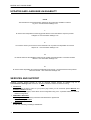
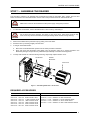
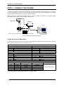
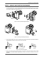
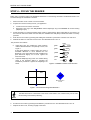
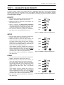
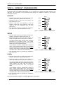
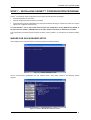
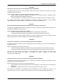
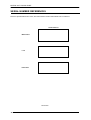
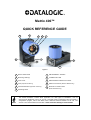
Matrix 400™
QUICK REFERENCE GUIDE
1
2
4
3
11
5
8
6
9
10
7
Figure A
1
Device Class Label
7
HMI X-PRESS™ Interface
2
Mounting Holes (4)
8
"POWER ON" LED
3
Lens Cover
9
Standard Serial Interface Connector
4
Lens (separate accessory)
10 Ethernet Connector (Ethernet Models Only)
5
Internal Illuminator (separate accessory)
11 Ethernet Connection LED
6
Mounting Holes
(Ethernet Models Only)
NOTE
This manual illustrates a Stand Alone application. For other types of installations, such as
Pass-Through, Multiplexer Layout, etc. and for a complete reader configuration using the VisiSet™
configuration program, refer to the Matrix 400™ Reference Manual available on the CD. This
manual is also downloadable from the Web at www.automation.datalogic.com/matrix400.
MATRIX 400™ QUICK GUIDE
UPDATES AND LANGUAGE AVAILABILITY
UK/US
The latest drivers and documentation updates for this product are available on Internet.
Log on to: www.automation.datalogic.com
I
Su Internet sono disponibili le versioni aggiornate di driver e documentazione di questo prodotto.
Collegarsi a: www.automation.datalogic.com
F
Les versions mises à jour de drivers et documentation de ce produit sont disponibles sur Internet.
Cliquez sur : www.automation.datalogic.com
D
Im Internet finden Sie die aktuellsten Versionen der Treiber und Dokumentation von diesem Produkt.
Adresse : www.automation.datalogic.com
E
En Internet están disponibles las versiones actualizadas de los drivers y documentación de este producto.
Dirección Internet : www.automation.datalogic.com
SERVICES AND SUPPORT
Datalogic provides several services as well as technical support through its website. Log on to
www.automation.datalogic.com and click on the links indicated for further information including:
•
PRODUCTS
Search through the links to arrive at your product page where you can download specific Manuals and
Software & Utilities including:
- VisiSet™ a utility program, which allows device configuration using a PC. It provides RS232 and Ethernet
interface configuration.
•
SERVICES & SUPPORT
- Datalogic Services - Warranty Extensions and Maintenance Agreements
- Authorised Repair Centres
•
CONTACT US
E-mail form and listing of Datalogic Subsidiaries
2
MATRIX 400™ QUICK GUIDE
STEP 1 – ASSEMBLE THE READER
The first step to perform is to assemble the accessories that make up the Matrix 400™ reader. The lens and
either an internal or an external illuminator must be used. This procedure shows an internal illuminator.
Matrix 400™ must be disconnected from the power supply during this procedure.
CAUTION
1.
In a dust-free environment, remove the Matrix 400™ Lens Cover by unscrewing it.
Do not touch the sensor aperture, lens glass or lens cover glass. These areas must be kept
clean. Avoid any abrasive substances that might damage these surfaces during cleaning.
CAUTION
2.
Remove the rubber sensor protection cap by pulling it out of the base.
3.
Mount the lens by screwing it tightly onto the base.
4.
If using an internal illuminator:
5.
a.
Mount the 4 internal illuminator spacers into the holes provided on the base.
b.
Align and mount the Illuminator board tightly onto the spacers using the 4 screws provided in the
illuminator package. The spacers are positioned asymmetrically to avoid incorrect alignment.
To keep dust and dirt off of the lens during mounting, temporarily replace the lens cover.
Set Screws
Internal
Illuminator
Lens Cover
Figure 1 – Assembling Matrix 400™ Accessories
REQUIRED ACCESSORIES
Lenses
93ACC1793
93ACC1794
93ACC1795
93ACC1796
93ACC1797
93ACC1798
93ACC1799
LNS-1006
LNS-1109
LNS-1112
LNS-1116
LNS-1125
LNS-1135
LNS-1150
6MM C-MOUNT LENS
9MM C-MOUNT LENS
12.5MM C-MOUNT LENS
16MM C-MOUNT LENS
25MM C-MOUNT LENS
35MM C-MOUNT LENS
50MM C-MOUNT LENS
Internal Illuminators
93A401019
93A401020
93A401021
93A401022
93A401024
LT-001
LT-002
LT-003
LT-004
LT-006
INTERNAL LT RED NARROW ANGLE
INTERNAL LT RED WIDE ANGLE
INTERNAL LT WHITE NARROW ANGLE
INTERNAL LT WHITE WIDE ANGLE
INTERNAL LT RED SUPER NARROW ANGLE
3
MATRIX 400™ QUICK GUIDE
STEP 2 – CONNECT THE SYSTEM
To connect the system in a Stand Alone configuration, you need the hardware indicated in Figure 2. In this layout
the data is transmitted to the Host on the main serial interface. Data can also be transmitted on the RS232
auxiliary interface independently from the main interface selection.
When One Shot or Phase Mode Operating mode is used, the reader is activated by an External Trigger
(photoelectric sensor) when the object enters its reading zone.
CAB-M01
Matrix 400™
CBOX-100
Host
P.S.*
Main Interface
PG 6000
* External Trigger or Presence Sensor (for On Shot or Phase Mode)
Figure 2 – Matrix 400™ in Stand Alone Layout
C-BOX 100 Pinout for Matrix 400™
The table below gives the pinout of the C-BOX 100 terminal block connectors. Use this pinout when the Matrix
400™ reader is connected by means of the C-BOX 100:
C-BOX 100 Terminal Block Connectors
Power
1, 3, 5
2, 4, 6
7, 8
20, 40
27
28
29
30
31, 33
32, 34
39
11, 15
12, 16
17
18
10, 14, 19
9, 13
VS
GND
EARTH GROUND
Reserved
Inputs
EXT TRIG A (polarity insensitive)
EXT TRIG B (polarity insensitive)
IN2 A
IN2 B
NC
NC
GND
RS232
TX 232
RTS 232
RX 232
CTS 232
GND
35
37
Outputs
OUT 1+
OUT 1OUT 2+
OUT 2NC
NC
Auxiliary Interface
TX AUX
RX AUX
36
38
Reserved
Reserved
21
22
23
24
25
26
Main Interface
RS485 Full-Duplex
RS485 Half-Duplex
TX 485+
RTX 485+
TX 485RTX 485*RX 485+
*RX 485GND
GND
RS485 Cable Shield
RS485 Cable Shield
* Do not leave floating, see Reference Manual for connection details.
4
20 mA C.L. (with INT-30 only)
see INT-30 instructions
MATRIX 400™ QUICK GUIDE
STEP 3 – MOUNT AND POSITION THE READER
1.
To mount the Matrix 400™, use the mounting brackets to obtain the most suitable position for the reader.
Two of the most common mounting configurations are shown in the figures below. Other mounting solutions
are provided in the Matrix 400™ Reference Manual.
Pitch
Tilt
Figure 3 –Positioning with Mounting Bracket (Back)
Pitch
Skew
Figure 4 –Positioning with Mounting Bracket (Side)
2.
When mounting the Matrix 400™ take into consideration these three ideal label position angles: Pitch or Skew 10°
to 20° and Tilt 0°, although the reader can read a code at any tilt angle.
P
T
S
Minimize
Assure at least 10°
Minimize
Figure 5 – Pitch, Skew and Tilt Angles
3.
Refer to the Optical Accessory Selection table in the Appendix of this Quick Reference Guide for FOV
calculation and minimum distance requirements according to the base/lens combination used for your
application.
5
MATRIX 400™ QUICK GUIDE
STEP 4 – FOCUS THE READER
Matrix 400™ provides a built-in tool called Blue Diamonds™ to aid focusing the reader. The Blue Diamonds™ are
accessed through the X-PRESS™ Interface.
1.
Remove the lens cover in order to focus the reader.
2.
Prepare the correct accessory lens for your application:
a.
Loosen the two set screws on the lens.
b.
Adjust the Focus ring to the "Far position" and the Diaphragm ring to the smallest "F" number setting
(diaphragm open).
3.
Power the reader on. During the reader startup (reset or restart phase), all the LEDs blink for one second. On
the connector side of the reader near the cable, the “POWER ON” LED (blue) indicates the reader is correctly
powered.
4.
Enter the Focus function by pressing and holding the X-PRESS™ push button until the Focus LED is on.
5.
Release the button to enter the Focus function. The Blue Diamonds™ turn on.
The procedure is as follows:
a.
READY
Adjust the Focus ring towards the "Near position"
until the Blue Diamonds™ are perfectly in focus, see
Figure 7.
At long focal distances a "skew" angle may cause a
noticeable difference in focus between the two
diamonds, in this case select the best possible focus
(both diamonds slightly out of focus. Tighten the
Focus set screw.
b.
Adjust the Diaphragm ring to the "F4" number setting
which is the preferred setting to complete the
installation procedures. Tighten the Diaphragm set
screw.
green
LEARN
GOOD
green
SETUP
TRIGGER
yellow
FOCUS
COM
yellow
TEST
STATUS
red
Figure 6 – X-PRESS™ Interface: Focus Function
FOV
Blue Diamond™
in focus
Figure 7 – Focus Function Using Blue Diamonds™
The Blue Diamonds™ a referenced to the center of the reader's FOV, therefore they can be used
for fine tuning of the reader positioning.
NOTE
6.
Exit the Focus function by pressing the X-PRESS™ push button once. The Blue Diamonds™ turn off.
7.
Replace the lens cover, screwing it tightly to the base.
6
MATRIX 400™ QUICK GUIDE
STEP 5 – CALIBRATE IMAGE DENSITY
In order to function correctly to the fullest extent of its capabilities, Matrix 400™ must acquire information
regarding image density or PPI (pixels per inch). This calibration takes place through the X-PRESS™ Interface
and a special Image Density Calibration chart. This procedure is necessary only for the first time installation
or if the lens type is changed.
LOCATE
READY
1. Enter the Focus function by pressing and holding the XPRESS™ push button until the Focus LED is on.
green
2. Release the button to enter the Focus function. The
Blue Diamonds™ turn on.
green
3. Select a code from the Image Density Calibration
chart that corresponds approximately to the size of one
of the Blue Diamonds™. Position the code at the center
of the FOV (equidistant from the Blue Diamonds™).
4. Exit the Focus function by pressing the X-PRESS™
push button once. The Blue Diamonds™ turn off.
LEARN
GOOD
SETUP
TRIGGER
yellow
FOCUS
COM
yellow
TEST
STATUS
red
Figure 8 – X-PRESS™ Interface: Locate Function
SETUP
5. Enter the Setup function by pressing and holding the XPRESS™ push button until the Setup LED is on.
READY
6. Release the button to enter the Setup function. The
Setup LED will blink until the procedure is completed.
green
The Setup procedure ends when the Image Acquisition
parameters are successfully saved in the reader
memory, the Setup LED will remain on continuously and
Matrix 400™ emits 3 high pitched beeps.
green
If the calibration cannot be reached after a timeout of
about 5 (five) seconds Matrix 400™ will exit without
saving the parameters to memory, the Setup LED will not
remain on continuously but it will just stop blinking. In this
case Matrix 400™ emits a long low pitched beep.
yellow
7. Exit the Setup function by pressing the X-PRESS™
push button once.
LEARN
GOOD
SETUP
TRIGGER
yellow
FOCUS
COM
TEST
STATUS
red
Figure 9 – X-PRESS™ Interface: Setup Function
LEARN
8. Enter the Learn function by pressing and holding the XPRESS™ push button until the Learn LED is on.
9. Release the button to enter the Learn function. The
Learn LED will blink until the procedure is completed.
The Learn procedure ends when the Image Processing
and Decoding parameters are successfully saved in the
reader memory, the Learn LED will remain on
continuously and Matrix 400™ emits 3 high pitched
beeps.
If the calibration cannot be reached after a timeout of
about 3 (three) minutes Matrix 400™ will exit without
saving the parameters to memory, the Learn LED will not
remain on continuously but it will just stop blinking. In this
case Matrix 400™ emits a long low pitched beep.
READY
green
LEARN
GOOD
green
SETUP
TRIGGER
yellow
FOCUS
COM
yellow
TEST
STATUS
red
Figure 10 – X-PRESS™ Interface: Learn Function
10. Exit the Setup function by pressing the X-PRESS™
push button once.
7
MATRIX 400™ QUICK GUIDE
STEP 6 – X-PRESS™ CONFIGURATION
Once Matrix 400™ has calibrated image density, you can configure it for optimal code reading relative to your
application. This configuration can be performed either through the X-PRESS™ Interface or the VisiSet™
configuration program.
LOCATE
READY
1. Enter the Focus function by pressing and holding the XPRESS™ push button until the Focus LED is on.
green
2. Release the button to enter the Focus function. The
Blue Diamonds™ turn on.
green
3. Select a code from your application or from the
Datalogic 1D/2D Test chart. Position the code at the
center of the FOV (equidistant from the Blue
Diamonds™).
4. Exit the Focus function by pressing the X-PRESS™
push button once. The Blue Diamonds™ turn off.
LEARN
GOOD
SETUP
TRIGGER
yellow
FOCUS
COM
yellow
TEST
STATUS
red
Figure 11 – X-PRESS™ Interface: Locate Function
SETUP
5. Enter the Setup function by pressing and holding the XPRESS™ push button until the Setup LED is on.
READY
6. Release the button to enter the Setup function. The
Setup LED will blink until the procedure is completed.
green
The Setup procedure ends when the Image Acquisition
parameters are successfully saved in the reader
memory, the Setup LED will remain on continuously and
Matrix 400™ emits 3 high pitched beeps.
green
If the calibration cannot be reached after a timeout of
about 5 (five) seconds Matrix 400™ will exit without
saving the parameters to memory, the Setup LED will not
remain on continuously but it will just stop blinking. In this
case Matrix 400™ emits a long low pitched beep.
yellow
7. Exit the Setup function by pressing the X-PRESS™
push button once.
LEARN
GOOD
SETUP
TRIGGER
yellow
FOCUS
COM
TEST
STATUS
red
Figure 12 – X-PRESS™ Interface: Setup Function
LEARN
8. Enter the Learn function by pressing and holding the XPRESS™ push button until the Learn LED is on.
9. Release the button to enter the Learn function. The
Learn LED will blink until the procedure is completed.
The Learn procedure ends when the Image Processing
and Decoding parameters are successfully saved in the
reader memory, the Learn LED will remain on
continuously and Matrix 400™ emits 3 high pitched
beeps.
If the calibration cannot be reached after a timeout of
about 3 (three) minutes Matrix 400™ will exit without
saving the parameters to memory, the Learn LED will not
remain on continuously but it will just stop blinking. In this
case Matrix 400™ emits a long low pitched beep.
READY
green
GOOD
green
SETUP
TRIGGER
yellow
FOCUS
COM
yellow
TEST
STATUS
red
Figure 13 – X-PRESS™ Interface: Learn Function
10. Exit the Setup function by pressing the X-PRESS™
push button once.
If you have used this procedure to configure Matrix 400™ go to step 8.
8
LEARN
MATRIX 400™ QUICK GUIDE
STEP 7 – INSTALLING VISISET™ CONFIGURATION PROGRAM
VisiSet™ is a Datalogic reader configuration tool providing several important advantages:
•
Autolearning Wizard for new users;
•
Defined configuration directly stored in the reader;
•
Communication protocol independent from the physical interface allowing to consider the reader as a remote
object to be configured and monitored.
To install VisiSet™, turn on the PC that will be used for the configuration, running Windows 98, 2000/NT or
XP, then insert the VisiSet™ CD-ROM, wait for the CD to autorun and follow the installation procedure.
This configuration procedure assumes a laptop computer, running VisiSet™, is connected to the reader's auxiliary
port.
WIZARD FOR QUICK READER SETUP
After installing and running the VisiSet™ software program the following window:
Figure 14 - VisiSet™ Opening Window
Set the communication parameters from the "Options" menu. Then select "Connect", the following window
appears:
Figure 15 - VisiSet™ Main Window After Connection
9
MATRIX 400™ QUICK GUIDE
The Autolearning Wizard option is advised for rapid configuration or for new users. It allows reader configuration
in a few easy steps.
1.
Select the Autolearning Wizard button from the Main menu.
2.
Place the desired code in front of the reader at the correct reading distance (see step 3 and the Optical
Accessory Selection table in the Appendix of this Quick Reference Guide).
3.
Press the "Positioning" button. The reader continuously acquires images and gives visual feedback in the
view image window to indicate when the code is centered with respect to the reader's FOV. Move the reader
(or code) to center it. Press the Positioning button again to stop positioning.
4.
Select a Calibration Mode choice and press the "Calibrate" button.
3
4
5
Autolearning
Result
The reader flashes once acquiring the image and auto determines the best exposure and gain settings. If the
code symbology is enabled by default, the code will also be decoded.
10
MATRIX 400™ QUICK GUIDE
5.
If the code symbology is not enabled by default, select a Code Setting Mode choice and press the "Code
Setting" button.
The Autolearning Result section of the Autolearning Wizard window shows the parameter settings and the code
type results.
6.
Select a Saving Options choice and press the "Save" button.
7.
Close the AutoLearning Wizard.
If your application has been configured using the VisiSet™ Autolearning Wizard, your reader is
ready. If necessary you can use VisiSet™ for advanced reader configuration.
NOTE
11
MATRIX 400™ QUICK GUIDE
STEP 8 – TEST MODE
Use a code suitable to your application to test the reading performance of the system. Alternatively, you can use
the Datalogic 1D/2D Test Chart (Code 39, Data Matrix ECC 200).
1.
Enter the Test function by pressing and holding the X-PRESS™ push button until the Test LED is on.
2.
Release the button to enter the Test function.
Once entered, the Bar Graph on the five LEDs is activated and if the reader starts reading codes the BarGraph shows the Good Read Rate. In case of no read condition, only the STATUS LED is on and blinks.
READY
green
LEARN
GOOD
green
SETUP
TRIGGER
yellow
FOCUS
COM
yellow
TEST
STATUS
red
Figure 16 – X-PRESS™ Interface: Test Function
3.
To exit the Test, press the X-PRESS™ push button once.
By default, the Test exits automatically after three minutes.
NOTE
The Bar Graph has the following meaning:
READY
≥ 95%
LEARN
GOOD
≥ 75%
SETUP
TRIGGER
≥ 60%
FOCUS
COM
≥ 40%
TEST
STATUS
≥ 20%
12
MATRIX 400™ QUICK GUIDE
ADVANCED READER CONFIGURATION
For further details on advanced product configuration, refer to the complete Reference Manual on the installation
CD-ROM or downloadable from the web site through this link: www.automation.datalogic.com/matrix400.
The following are alternative or advanced reader configuration methods:
ADVANCED CONFIGURATION USING VISISET™
Advanced configuration can be performed through the VisiSet™ program by selecting Device> Get Configuration
From Temporary Memory to open the Parameter Setup window in off-line mode. Advanced configuration is
addressed to expert users being able to complete a detailed reader configuration. The desired parameters can be
defined in the various folders of the Parameter Setup window and then sent to the reader memory (either
Temporary or Permanent):
Figure 17 - VisiSet™ Parameter Setup Window
HOST MODE PROGRAMMING
The reader can also be configured from a host computer using the Host Mode programming procedure, by
commands via the serial interface. See the Host Mode Programming file on the CD-ROM.
ALTERNATIVE LAYOUTS
If you need to install an Ethernet network, Pass-Through network, Multiplexer network or an RS232 Master/Slave
refer to the Matrix 400™ Reference Manual.
13
MATRIX 400™ QUICK GUIDE
APPENDIX
X-PRESS™ is the intuitive Human Machine Interface designed to improve ease of installation and maintenance.
Status and diagnostic information are clearly presented by means of the five colored LEDs, whereas the single
push button gives immediate access to the following relevant functions:
•
Test with bar graph visualization to check static reading performance
•
Focus/Locate to turn on the Blue Diamonds™ to aid focusing and positioning.
•
Setup to perform Exposure Time and Gain calibration.
•
Learn to self-detect and auto-configure for reading unknown codes
In normal operating mode the colors and meaning of the five LEDs are illustrated in the following table:
READY (green)
GOOD (green)
TRIGGER (yellow)
COM (yellow)
STATUS (red)
This LED indicates the device is ready to operate.
This LED confirms successful reading.
This LED indicates the status of the reading phase.
This LED indicates active communication on main serial port.
This LED indicates a NO READ result.
During the reader startup (reset or restart phase), all the LEDs blink for one second.
On the connector side of the reader near the cable, the blue POWER ON LED indicates the reader is correctly
powered.
For Ethernet models, on the connector side of the reader near the Ethernet connector, the orange NETWORK
PRESENCE LED indicates Ethernet network connection.
14
MATRIX 400™ QUICK GUIDE
OPTICAL ACCESSORY SELECTION
Refering to Figure 18 and the formula below, use the data in the following table to calculate the FOV for your
application.
Viewing Angle
Horizontal
Viewing
Angle
Vertical
Viewing
Angle
Diagonal
Min Focus Distance
mm
400-400-0x0
(SXGA)
LNS-1109 9mm
LNS-1112 12.5mm
LNS-1116 16mm
LNS-1125 25mm
LNS-1135 35mm
LNS-1150 50mm
48.5°
37°
28.5°
18.5°
13°
9°
39.5°
30°
23°
15°
10,5°
7°
60°
46.5°
36°
23.5°
16.5°
11.5°
85
85
85
135
235
500
LT-002
LT-002
LT-001
LT-001
LT-006
LT-006
400-600-0x0
(UXGA)
LNS-1006 6mm
LNS-1109 9mm
LNS-1112 12,5mm
LNS-1116 16mm
LNS-1125 25mm
LNS-1135 35mm
LNS-1150 50mm
59.5°
40.5°
31°
24°
15°
11°
7.5°
46.5°
31°
23.5°
18°
11.5°
8.5°
5.5°
71°
49.5°
38°
30°
19°
13.5°
9.5°
85
85
85
85
135
235
500
LT-002
LT-002
LT-002
LT-001
LT-001
LT-006
LT-006
Model
Lens
Lighting System
The viewing angle has a tolerance of ± 1° depending on the focus distance.
FOVx = 2 (d + 35 mm) tan (αx/2)
where:
FOVx = horizontal, vertical or diagonal FOV
αx = horizontal, vertical or diagonal viewing angles.
d = focus distance
35 mm
d
α
FOV
plane
Figure 18 – Reading Distance References
Example:
The FOV for a Matrix 400-600-0x0 base using the 16 mm lens at a focus distance of 200 mm is:
FOVH = 2 [(200 mm + 35 mm) tan (24°/2)] = 100 mm
FOVV = 2 [(200 mm + 35 mm) tan (18°/2)] = 74 mm
15
MATRIX 400™ QUICK GUIDE
TECHNICAL FEATURES
ELECTRICAL FEATURES
Power
Supply Voltage
Power Consumption
Communication Interfaces
Main
- RS232
- RS485 full-duplex
- RS485 half-duplex
Auxiliary - RS232
Ethernet (Ethernet Models only)
Inputs
External Trigger and IN2
Outputs
OUT1 and OUT2
10 to 30 Vdc
8 W max.; 5 W typical
2400 to 115200 bit/s
2400 to 115200 bit/s
2400 to 115200 bit/s
2400 to 115200 bit/s
10/100 Mbit/s
Opto-coupled and polarity insensitive
Opto-coupled
OPTICAL FEATURES
400-4xx-xxx models
Image Sensor
Image Format
Frame Rate
Pitch
Tilt
Lighting System
LED Safety Class
CMOS
CCD
SXGA (1280x1024)
UXGA (1600x1200)
27 frames/sec.
15 frames/sec.
± 35°
0° - 360°
Internal or External Illuminator (accessories)
Class 1 to EN60825-1
400-6xx-xxx models
USER INTERFACE
LED Indicators
Keypad Button
Power, Ready, Good; Trigger; Com, Status, (Network); (Green Spot)
Configurable via VisiSet™
SOFTWARE FEATURES
Readable Code Symbologies
1-D and stacked
• PDF417 Standard and Micro PDF417
• Code 128 (EAN 128)
• Code 39 (Standard and Full ASCII)
• Interleaved 2 of 5
• Codabar
• Code 93
• Pharmacode
• EAN-8/13 - UPC-A/E
(including Addon 2 and Addon 5)
• GS1 DataBar (RSS) Family
• Composite Symbologies
Operating Mode
Configuration Methods
Parameter Storage
2-D
• Data Matrix ECC 200
(Standard and Direct Marking)
• QR Code
(Standard and Direct Marking)
• MAXICODE
• Aztec Code
• Microglyph
(this symbology requires an
activation procedure – contact your
local Datalogic Automation
distributor for details)
•
•
•
•
•
•
•
POSTAL
Australia Post
Royal Mail 4 State Customer
Kix Code
Japan Post
PLANET
POSTNET, POSTNET (+BB)
POSTNET + PLANET,
POSTNET (+BB) + PLANET
ONE SHOT, CONTINUOUS, PHASE MODE
By means of X-PRESS™ Human Machine Interface or VisiSet™ configuration
software
Permanent memory (Flash)
CODE QUALITY VERIFICATION
Standard
ISO/IEC 16022
ISO/IEC 18004
ISO/IEC 15415
ISO/IEC 15416
AS9132A
Supported Symbologies
Data Matrix ECC 200
QR Code
Data Matrix ECC 200, QR Code
Code 128, Code 39, Interleaved 2 of 5, Codabar, Code 93, EAN-8/13, UPC-A/E
Data Matrix ECC 200
MECHANICAL FEATURES
Dimensions
Weight
Material
123 x 60.5 x 87 mm (4.85 x 2.38 x 3.43 in.) with lens cover
482 g. (17 oz.) with lens and internal illuminator
Aluminium
ENVIRONMENTAL FEATURES
Operating Temperature
Storage Temperature
Max. Humidity
Protection Class
16
0 to 50 °C (32 to 122 °F)
-20 to 70 °C (-4 to 158 °F)
90% non condensing
IP67
MATRIX 400™ QUICK GUIDE
109
[4.29]
123.2
[4.85]
30.25
[1.19]
MECHANICAL DIMENSIONS
60.5
[2.38]
18
[0.71]
41.5
[1.63]
87
[3.43]
Ø61
[Ø2.40]
Figure 19 – Matrix 400™ Overall Dimensions
12.5
[0.49]
=
=
12.5
[0.49]
12.5
[0.49]
30°
45°
8.5 3]
3
[0.
=
=
30°
45°
Ø4.2
[Ø0
.17]
72.5
[2.85]
4.2
[0.17]
12.5
[0.49]
3
[0.12]
=
=
40
[1.57]
=
25
Ø8. 2]
.3
[Ø0
M4
[0.16] N°5
23
[0.91]
4.3
[0.17]
4
[0.16]
38
[1.50]
45°
4.2
[0.17]
45°
83.5
[3.29]
50
[1.97]
70
[2.76]
=
61
[2.40]
50
[1.97]
4.2
[0.17]
Figure 20 – Mounting Brackets Overall Dimensions
17
MATRIX 400™ QUICK GUIDE
PATENTS
This product is covered by one or more of the following patents:
U.S. patents: 6,512,218 B1; 6,616,039 B1; 6,808,114 B1; 6,997,385 B2
European patents: 999,514 B1; 1,014,292 B1; 1,128,315 B1.
Additional patents pending.
COMPLIANCE
EMC COMPLIANCE
In order to meet the EMC requirements:
•
connect reader chassis to the plant earth ground by means of a flat copper braid shorter than 100 mm;
•
connect pin 7,8 of the C-Box 100 to a good Earth Ground;
POWER SUPPLY
This product is intended to be installed by Qualified Personnel only.
This product is intended to be connected to a UL Listed Computer which supplies power directly to the reader or a
UL Listed Direct Plug-in Power Unit marked LPS or “Class 2”, rated 10 to 30 V, minimum 1 A.
CE COMPLIANCE
Warning: This is a Class A product. In a domestic environment this product may cause radio interference in
which case the user may be required to take adequate measures.
WEEE COMPLIANCE
ENGLISH
Information for the user in accordance with the European Commission Directive 2002/96/EC
At the end of its useful life, the product marked with the crossed out wheeled wastebin must be disposed of
separately from urban waste.
Disposing of the product according to this Directive:
•
•
avoids potentially negative consequences to the environment and human health which otherwise could
be caused by incorrect disposal
enables the recovery of materials to obtain a significant savings of energy and resources.
For more detailed information about disposal, contact the supplier that provided you with the product in question
or consult the dedicated section at the website www.automation.datalogic.com.
18
MATRIX 400™ QUICK GUIDE
ITALIANO
Informazione degli utenti ai sensi della Direttiva Europea 2002/96/EC
L’apparecchiatura che riporta il simbolo del bidone barrato deve essere smaltita, alla fine della sua vita utile,
separatamente dai rifiuti urbani.
Smaltire l’apparecchiatura in conformità alla presente Direttiva consente di:
•
evitare possibili conseguenze negative per l’ambiente e per la salute umana che potrebbero invece
essere causati dall’errato smaltimento dello stesso;
•
recuperare materiali di cui è composto al fine di ottenere un importante risparmio di energia e di risorse.
Per maggiori dettagli sulle modalità di smaltimento, contattare il Fornitore dal quale è stata acquistata
l’apparecchiatura o consultare la sezione dedicata sul sito www.automation.datalogic.com.
DEUTSCH
Benutzerinformation bezüglich Richtlinie 2002/96/EC der europäischen Kommission
Am Ende des Gerätelebenszyklus darf das Produkt nicht über den städtischen Hausmüll entsorgt werden. Eine
entsprechende Mülltrennung ist erforderlich.
Beseitigung des Produkts entsprechend der Richtlinie:
•
verhindert negative Auswirkungen für die Umwelt und die Gesundheit der Menschen
•
ermöglicht die Wiederverwendung der Materialien und spart somit Energie und Resourcen
Weitere Informationen zu dieser Richtlinie erhalten sie von ihrem Lieferanten über den sie das Produkt erworben
haben, oder besuchen sie unsere Hompage unter www.automation.datalogic.com.
FRANÇAIS
Information aux utilisateurs concernant la Directive Européenne 2002/96/EC
Au terme de sa vie utile, le produit qui porte le symbole d'un caisson à ordures barré ne doit pas être éliminé avec
les déchets urbains.
Éliminer ce produit selon cette Directive permet de:
•
éviter les retombées négatives pour l'environnement et la santé dérivant d'une élimination incorrecte
•
récupérer les matériaux dans le but d'une économie importante en termes d'énergie et de ressources
Pour obtenir des informations complémentaires concernant l'élimination, veuillez contacter le fournisseur auprès
duquel vous avez acheté le produit ou consulter la section consacrée au site Web
www.automation.datalogic.com.
ESPAÑOL
Información para el usuario de accuerdo con la Directiva Europea 2002/96/CE
Al final de su vida útil, el producto marcado con un simbolo de contenedor de bassura móvil tachado no debe
eliminarse junto a los desechos urbanos.
Eliminar este producto de accuerdo con la Directiva permite de:
•
•
evitar posibles consecuencias negativas para el medio ambiente y la salud derivadas de una eliminación
inadecuada
recuperar los materiales obteniendo así un ahorro importante de energía y recursos
Para obtener una información más detallada sobre la eliminación, por favor, póngase en contacto con el
proveedor donde lo compró o consultar la sección dedicada en el Web site www.automation.datalogic.com.
19
MATRIX 400™ QUICK GUIDE
SERIAL NUMBER REFERENCES
Place the replicate Matrix 400™ base, lens and illuminator serial number labels here for reference.
Serial Numbers
Matrix 400™
Lens
Illuminator
821001350
20