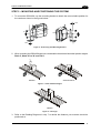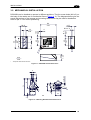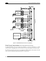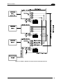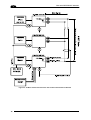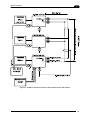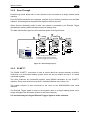
1
DS2100N Reference Manual Datalogic Automation Srl Via S. Vitalino, 13 40012 - Lippo di Calderara di Reno Bologna - Italy DS2100N Reference Manual Ed.: 07/2007 ALL RIGHTS RESERVED Datalogic reserves the right to make modifications and improvements without prior notification. Datalogic shall not be liable for technical or editorial errors or omissions contained herein, nor for incidental or consequential damages resulting from the use of this material. Product names mentioned herein are for identification purposes only and may be trademarks and or registered trademarks of their respective companies. © Datalogic Automation S.r.l. 2007 12/07/07 CONTENTS REFERENCES ............................................................................................................. v Conventions.................................................................................................................. v Reference Documentation ............................................................................................ v Services and Support ................................................................................................... v Patents.......................................................................................................................... v SAFETY REGULATIONS ........................................................................................... vi Laser Safety................................................................................................................. vi Power Supply...............................................................................................................vii CE Compliance............................................................................................................vii WEEE Compliance ......................................................................................................vii GENERAL VIEW ......................................................................................................... ix 1 RAPID CONFIGURATION ........................................................................................... 1 Step 1 – Connect the System ....................................................................................... 1 Step 2 – Mounting and Positioning the System ............................................................ 3 Step 3 – X-PRESS™ Configuration.............................................................................. 4 Step 4 – Installing Genius™ Configuration Program .................................................... 7 Step 5 – Test Mode .................................................................................................... 12 Advanced Scanner Configuration ............................................................................... 13 2 2.1 2.1.1 2.2 2.2.1 2.3 2.3.1 2.3.2 2.4 2.5 INTRODUCTION ........................................................................................................ 14 Product Description .................................................................................................... 14 Indicators .................................................................................................................... 15 ID-NET™ .................................................................................................................... 15 How To Setup/Configure the Scanner Network.......................................................... 16 X-PRESS™ Human Machine Interface ...................................................................... 17 Diagnostic Indication................................................................................................... 17 X-PRESS™ Functions................................................................................................ 18 Model Description ....................................................................................................... 20 Accessories ................................................................................................................ 21 3 3.1 3.2 3.2.1 3.2.2 3.3 3.3.1 3.3.2 3.3.3 3.3.4 3.3.5 3.3.6 3.4 3.5 3.6 3.6.1 3.6.2 3.6.3 3.6.4 INSTALLATION ......................................................................................................... 22 Package Contents ...................................................................................................... 22 Mechanical Installation ............................................................................................... 23 Mounting DS2100N .................................................................................................... 24 Mounting Scanner Accessories .................................................................................. 25 Electrical Connections ................................................................................................ 26 Power Supply.............................................................................................................. 28 Main Serial Interface................................................................................................... 28 ID-NET™ Interface ..................................................................................................... 33 Auxiliary RS232 Interface ........................................................................................... 38 Inputs .......................................................................................................................... 39 Outputs ....................................................................................................................... 41 User Interface ............................................................................................................. 42 Positioning .................................................................................................................. 43 Typical Layouts........................................................................................................... 44 Point-to-Point .............................................................................................................. 44 Pass-Through ............................................................................................................. 45 ID-NET™ .................................................................................................................... 45 RS232 Master/Slave................................................................................................... 47 iii 3.6.5 Multiplexer Layout....................................................................................................... 48 4 4.1 4.1.1 4.1.2 4.2 4.2.1 4.2.2 4.3 4.3.1 4.4 READING FEATURES............................................................................................... 49 Advanced Code Builder (ACB) ................................................................................... 49 Important ACB Reading Conditions............................................................................ 50 Tilt Angle Improvement with ACB ............................................................................... 50 Linear Code Reading.................................................................................................. 50 Step-Ladder Mode ...................................................................................................... 51 Picket-Fence Mode..................................................................................................... 52 Performance ............................................................................................................... 53 Raster ......................................................................................................................... 53 Reading Diagrams ...................................................................................................... 54 5 5.1 MAINTENANCE ......................................................................................................... 59 Cleaning...................................................................................................................... 59 6 6.1 TROUBLESHOOTING ............................................................................................... 60 General Guidelines ..................................................................................................... 60 7 TECHNICAL FEATURES........................................................................................... 63 GLOSSARY................................................................................................................ 65 INDEX......................................................................................................................... 68 iv REFERENCES CONVENTIONS This manual uses the following conventions: “User” or “Operator” refers to anyone using a DS2100N. “Device” refers to the DS2100N. “You” refers to the System Administrator or Technical Support person using this manual to install, mount, operate, maintain or troubleshoot a DS2100N. REFERENCE DOCUMENTATION The documentation related to the DS2100N management is listed below: • C-BOX 100 Installation Manual • C-BOX 150 Installation Manual • INT-30 20 mA Current Loop Interface Board for C-Box 100/150 • C-BOX 300/310 Installation Manual • C-BOX 400/410 Installation Manual • OM2000N Installation Manual • Genius™ Help On Line SERVICES AND SUPPORT Datalogic provides several services as well as technical support through its website. Log on to www.automation.datalogic.com and click on the links indicated for further information including: • PRODUCTS Search through the links to arrive at your product page where you can download specific Manuals and Software & Utilities • SERVICES & SUPPORT - Datalogic Services - Warranty Extensions and Maintenance Agreements - Authorised Repair Centres • CONTACT US E-mail form and listing of Datalogic Subsidiaries PATENTS This product is covered by one or more of the following patents: U.S. patent 5,992,740 European patent 789,315 B1 v SAFETY REGULATIONS LASER SAFETY The following information is provided to comply with the rules imposed by international authorities and refers to the correct use of the DS2100N scanner. Standard Regulations This scanner utilizes a low-power laser diode. Although staring directly at the laser beam momentarily causes no known biological damage, avoid staring at the beam as one would with any very strong light source, such as the sun. Avoid that the laser beam hits the eye of an observer, even through reflective surfaces such as mirrors, etc. This product conforms to the applicable requirements of both EN 60825-1and CDRH 21 CFR 1040 at the date of manufacture. The scanner is classified as a Class 2 laser product according to EN 60825-1 regulations and as a Class II laser product according to CDRH regulations. There is a safety device, which allows the laser to be switched on only if the motor is rotating above the threshold for its correct scanning speed. The laser beam can be switched off through a software command (see also the Genius™ Help On Line). WARNING Use of controls or adjustments or performance of procedures other than those specified herein may result in exposure to hazardous visible laser light. The laser light is visible to the human eye and is emitted from the window on the front of the scanner (Figure A, 7). Warning labels indicating exposure to laser light and the device classification are applied onto the body of the scanner (Figure A, 1). vi Disconnect the power supply when opening the device during maintenance or installation to avoid exposure to hazardous laser light. The laser diode used in this device is classified as a class 3B laser product according to EN 60825-1 regulations and as a Class IIIb laser product according to CDRH regulations. This product conforms to the applicable requirements of 21CFR1040 at the date of manufacture Any violation of the optic parts in particular can cause radiation up to the maximum level of the laser diode (35 mW at 630 to 680 nm). LASER LIGHT DO NOT STARE INTO BEAM CLASS 2 LASER PRODUCT MAX. OUTPUT RADIATION 1 mW EMITTED WAVE LENGTH 630~680 nm TO EN 60825-1:2001 CAUTION-CLASS 3B LASER LIGHT WHEN OPEN AVOID EXPOSURE TO BEAM Pat. US5992740, EP0789315B1 DATALOGIC AUTOMATION Srl Via S. Vitalino, 13 – 40012 Calderara di Reno MADE IN ITALY-www.datalogic.com AVOID EXPOSURE LASER LIGHT IS EMITTED FROM THIS APERTURE Warning and Device Class Labels POWER SUPPLY This product is intended to be installed by Qualified Personnel only. This accessory device is intended to be supplied by a UL Listed or CSA Certified Power Unit with «Class 2» or LPS power source, which supplies power directly to the scanner via the 25pin connector. CE COMPLIANCE Warning: This is a Class A product. In a domestic environment this product may cause radio interference in which case the user may be required to take adequate measures. WEEE COMPLIANCE ENGLISH Information for the user in accordance with the European Commission Directive 2002/96/EC At the end of its useful life, the product marked with the crossed out wheeled wastebin must be disposed of separately from urban waste. Disposing of the product according to this Directive: • avoids potentially negative consequences to the environment and human health which otherwise could be caused by incorrect disposal • enables the recovery of materials to obtain a significant savings of energy and resources. For more detailed information about disposal, contact the supplier that provided you with the product in question or consult the dedicated section at the website www.automation.datalogic.com. vii ITALIANO Informazione degli utenti ai sensi della Direttiva Europea 2002/96/EC L’apparecchiatura che riporta il simbolo del bidone barrato deve essere smaltita, alla fine della sua vita utile, separatamente dai rifiuti urbani. Smaltire l’apparecchiatura in conformità alla presente Direttiva consente di: • evitare possibili conseguenze negative per l’ambiente e per la salute umana che potrebbero invece essere causati dall’errato smaltimento dello stesso; • recuperare materiali di cui è composto al fine di ottenere un importante risparmio di energia e di risorse. Per maggiori dettagli sulle modalità di smaltimento, contattare il Fornitore dal quale è stata acquistata l’apparecchiatura o consultare la sezione dedicata sul sito www.automation.datalogic.com. DEUTSCH Benutzerinformation bezüglich Richtlinie 2002/96/EC der europäischen Kommission Am Ende des Gerätelebenszyklus darf das Produkt nicht über den städtischen Hausmüll entsorgt werden. Eine entsprechende Mülltrennung ist erforderlich. Beseitigung des Produkts entsprechend der Richtlinie: • verhindert negative Auswirkungen für die Umwelt und die Gesundheit der Menschen • ermöglicht die Wiederverwendung der Materialien und spart somit Energie und Resourcen Weitere Informationen zu dieser Richtlinie erhalten sie von ihrem Lieferanten über den sie das Produkt erworben haben, oder besuchen sie unsere Hompage unter www.automation.datalogic.com. FRANÇAIS Information aux utilisateurs concernant la Directive Européenne 2002/96/EC Au terme de sa vie utile, le produit qui porte le symbole d'un caisson à ordures barré ne doit pas être éliminé avec les déchets urbains. Éliminer ce produit selon cette Directive permet de: • éviter les retombées négatives pour l'environnement et la santé dérivant d'une élimination incorrecte • récupérer les matériaux dans le but d'une économie importante en termes d'énergie et de ressources Pour obtenir des informations complémentaires concernant l'élimination, veuillez contacter le fournisseur auprès duquel vous avez acheté le produit ou consulter la section consacrée au site Web www.automation.datalogic.com. ESPAÑOL Información para el usuario de accuerdo con la Directiva Europea 2002/96/CE Al final de su vida útil, el producto marcado con un simbolo de contenedor de bassura móvil tachado no debe eliminarse junto a los desechos urbanos. Eliminar este producto de accuerdo con la Directiva permite de: • evitar posibles consecuencias negativas para el medio ambiente y la salud derivadas de una eliminación inadecuada • recuperar los materiales obteniendo así un ahorro importante de energía y recursos Para obtener una información más detallada sobre la eliminación, por favor, póngase en contacto con el proveedor donde lo compró o consultar la sección dedicada en el Web site www.automation.datalogic.com. viii GENERAL VIEW DS2100N 4 5 6 3 2 1 7 10 9 8 11 Figure A 1 Warning and Device Class Labels 7 Laser Beam Output Window 2 "POWER ON" LED 8 "COM" LED 3 Mounting Holes 9 "STATUS" LED 4 "READY" LED 10 Push Button 5 "GOOD" LED 11 Accessory Mounting Holes 6 "TRIGGER" LED ix x RAPID CONFIGURATION 1 1 RAPID CONFIGURATION STEP 1 – CONNECT THE SYSTEM To connect the system in a Stand Alone configuration, you need the hardware indicated in Figure 1. In this layout the data is transmitted to the Host on the main serial interface. In Local Echo communication mode, data is transmitted on the RS232 auxiliary interface independently from the main interface selection. When On-Line Operating mode is used, the scanner is activated by an External Trigger (photoelectric sensor) when the object enters its reading zone. DS2100N CBOX-100/150 Host P.S.* * Presence Sensor (for On-Line mode) PG 6000 Figure 1 – DS2100N in Stand Alone Layout 1 DS2100N REFERENCE MANUAL 1 C-BOX 100/150 Pinout for DS2100N The table below gives the pinout of the C-BOX 100/150 terminal block connectors. Use this pinout when the DS2100N reader is connected by means of the C-BOX 100/150: 1, 3, 5 2, 4, 6 7, 8 20, 40 27 28 29 30 31, 33 32, 34 39 11, 15 12, 16 17 18 10, 14, 19 C-BOX 100/150 Terminal Block Connectors Power Outputs VS 21 OUT 1+ GND 22 OUT 1EARTH GROUND 23 OUT 2+ Reserved 24 OUT 225 NC Inputs EXT TRIG A (polarity insensitive) 26 NC EXT TRIG B (polarity insensitive) Auxiliary Interface NC 35 TX AUX IN237 RX AUX NC ID-NET™ NC 36 ID-NETGND 38 ID-NET+ Main Interface RS485 Full20 mA C.L. (with RS232 RS485 Half-Duplex INT-30 only) Duplex TX 232 TX 485+ RTX 485+ RTS 232 TX 485RTX 485RX 232 *RX 485+ see INT-30 CTS 232 *RX 485instructions SGND SGND SGND 9, 13 RS485 Cable Shield RS485 Cable Shield * Do not leave floating, see par. "RS485 Full-Duplex Interface" for connection details. CAUTION 2 Do not connect GND and SGND to different (external) ground references. GND and SGND are internally connected through filtering circuitry which can be permanently damaged if subjected to voltage drops over 0.8 Vdc. RAPID CONFIGURATION 1 STEP 2 – MOUNTING AND POSITIONING THE SYSTEM 1. To mount the DS2100N, use the mounting bracket to obtain the most suitable position for the reader as shown in the figures below. Skew Tilt Pitch Skew Figure 2 - Positioning with Mounting Bracket 2. When mounting the DS2100N take into consideration these three ideal label position angles: Pitch 0°, Skew 10° to 30° and Tilt 0°. P S Minimize Assure at least 10° Figure 3 – Pitch and Skew Angles T Minimize Figure 4 – Tilt Angle 3. Refer to the Reading Diagrams in chp. 7 to decide the distance your scanner should be positioned at. 3 DS2100N REFERENCE MANUAL 1 STEP 3 – X-PRESS™ CONFIGURATION X-PRESS™ is the intuitive Human Machine Interface designed to improve ease of installation and maintenance. Status and diagnostic information are clearly presented by means of the five colored LEDs, whereas the single push button gives immediate access to the following relevant functions: • Test Mode (F1) with bar graph visualization to check static reading performance • AutoLearn (F2) to self-detect and auto-configure for reading unknown barcodes (by type and length) • AutoSetup (F3) to self-optimize and auto-configure reading performance in demanding applications NOTE If using the OM2000N accessory, when entering the X-PRESS™ interface, the Oscillating Mirror remains in the default fixed position (-15°) in order to make barcode reading easier while performing the X-PRESS™ functions. The colors and meaning of the five LEDs are illustrated in the following table: F4 READY (green) This LED indicates the device is ready to operate. F3 GOOD (green) This LED confirms successful reading. F2 TRIGGER (yellow) This LED indicates the status of the reading phase. F1 COM (yellow) This LED indicates active communication on main serial port. F0 STATUS (red) This LED indicates a NO READ result. During the reader startup (reset or restart phase), all the LEDs blink for one second. On the back of the reader near the cable, the “POWER ON” LED indicates the laser scanner is correctly powered. 4 RAPID CONFIGURATION 1 Auto Learn If you are configuring your scanner using X-PRESS™, you must start with the Auto Learn procedure. 1. Enter the Auto Learn function (F2) by pressing the X-PRESS™ push button. 2. Hold the push button pressed until the F2 LED is on. 3. Release the button to enter the Auto Learn function. Once entered, the reader starts a procedure to automatically detect and recognize barcodes (by type and length), which are presented to it (*). The laser turns on and the TRIGGER LED blinks to indicate the ongoing process. The procedure is as follows: F4 AutoSetup F3 AutoLearn F2 Test Mode Exit F1 F0 READY GOOD TRIGGER COM STATUS Figure 5 – X-PRESS™ Interface: Auto Learn Function A) place the desired barcode on the scanline. B) wait until the TRIGGER LED stays steady on (indicating the reader has detected the barcode). C) repeat, if needed, the above two steps to program up to 10 different barcodes (either by length or by symbology). If more than one barcode is detected, the Multi Label mode is enabled (refer to the “2000 Family Software Configuration Parameter Guide” Help file). 4. Exit the process by pressing the X-PRESS™ push button once. The scanner will restart at the end of the process, and then the detected barcodes are automatically configured in scanner memory. NOTE If the barcode cannot be read because of low contrast or excessive ambient light, you can perform the AutoSetup function to optimize the optical parameters. Then you can perform AutoLearn to recognize the barcode symbology. 5 DS2100N REFERENCE MANUAL 1 Auto Setup (Optional) At the end of the Auto Learn procedure, you have the possibility to follow the Auto Setup procedure to set up the reading parameters. 1. Enter the Auto Setup function (F3) by pressing the X-PRESS™ push button. 2. Hold the push button pressed until the F3 LED is on. 3. Release the button to enter the Auto Setup function. 4. Once entered, if a barcode label is positioned in front of the scanline, the scanner automatically performs the optimal setup of the reading parameters for that specific barcode. F4 AutoSetup F3 AutoLearn F2 Test Mode Exit F1 F0 READY The procedure is as follows: GOOD A) place the desired barcode on the scanline. TRIGGER COM STATUS Figure 6 – X-PRESS™ Interface: Auto Setup Function B) enter the AutoSetup function (the laser turns on and the GOOD LED blinks to indicate the ongoing process) C) wait until the GOOD LED stays steady on (indicating the reader has detected the barcode) This procedure ends either when the barcode is successfully decoded or after a timeout of about 7 (seven) seconds. The scanner will restart at the end of the process, and then the optimized reading parameters for that barcode are automatically configured in scanner memory. If your application has been configured using X-PRESS™, go to STEP 5. NOTE 6 RAPID CONFIGURATION 1 STEP 4 – INSTALLING GENIUS™ CONFIGURATION PROGRAM Genius™ is a Datalogic scanner configuration tool providing several important advantages: • Wizard approach for new users; • Multi-language version; • Defined configuration directly stored in the reader; • Communication protocol independent from the physical interface allowing to consider the reader as a remote object to be configured and monitored. To install Genius™, turn on the PC that will be used for the configuration, running Windows 98, 2000/NT or XP, then insert the Genius™ CD-ROM, wait for the CD to autorun and follow the installation procedure. This configuration procedure assumes scanner connection to a C-BOX 100/150. Genius™, running on a laptop computer, is connected to the scanner auxiliary port through the C-BOX 100/150 9-pin connector. Wizard for Quick Reader Setup After installing the Genius™ software program the following window appears asking the user to choose the desired configuration level. Figure 7 - Genius™ Wizard Opening Window The Wizard option is advised for rapid configuration or new users, since it shows a step-bystep scanner configuration. 7 DS2100N REFERENCE MANUAL 1 1. Select the Create a new configuration button. You will be guided through the configuration being asked to define the following parameters: a. 8 Barcode selection and definition RAPID CONFIGURATION b. Operating mode selection and definition c. Digital Outputs configuration 1 9 DS2100N REFERENCE MANUAL 1 d. Hardware interface selection e. Output data format configuration The On Line operating Mode requires the reader to be connected to an external Presence Sensor using EXT TRIG/PS A and EXT TRIG/PS B inputs. The Automatic operating mode does not require connection to an external Presence Sensor. When working in this mode the reader is continuously scanning, while the reading phase is activated each time a barcode enters the reader reading zone. The reader stops reading after an N number of scans without a code. Barcode characters are transmitted on the serial interface. In case of a failed reading phase no message is sent to the host computer. 10 RAPID CONFIGURATION 1 2. After defining the parameter values the following window appears allowing to complete the reader configuration as follows: • Saving the configuration to disk; • Switching to Advanced mode; • Sending the configuration to the scanner. 3. After sending the configuration to the scanner you have completed the configuration process. 4. By clicking Finish, the System Information window will be displayed with specific information concerning the scanner. 11 DS2100N REFERENCE MANUAL 1 STEP 5 – TEST MODE Use a code suitable to your application to test the system. Alternatively, you can use the Datalogic Test Chart (Code 39, Code Interleaved 2/5). 1. Enter the Test mode function (F1) by pressing the X-PRESS™ push button. 2. Hold the push button pressed until the F1 LED is on. 3. Release the button to enter the Test mode function. Once entered, the Bar Graph on the five LEDs is activated and if the scanner starts reading barcodes the Bar-Graph shows the Good Read Rate. In case of no read condition, only the STATUS LED is on and blinks. F4 AutoSetup F3 AutoLearn F2 Test Mode Exit F1 F0 READY GOOD TRIGGER COM STATUS Figure 8 – X-PRESS™ Interface: Test Mode Function 4. To exit the Test Mode, press the X-PRESS™ push button once. By default, the Test Mode exits automatically after two minutes. NOTE 12 RAPID CONFIGURATION 1 ADVANCED SCANNER CONFIGURATION For further details on advanced product configuration, refer to the complete Reference Manual on the installation CD-ROM or downloadable from the web site through this link: www.automation.datalogic.com/ds2100n. The following are alternative or advanced scanner configuration methods: Host Mode Programming The scanner can also be configured from a host computer using the Host Mode programming procedure, by commands via the serial interface. See the Host Mode Programming file on the CD-ROM. Advanced Genius™ Configuration The ADVANCED selection available when starting the Genius™ program is addressed to expert users being able to complete a detailed scanner configuration. By choosing this option it is possible either to start a new scanner configuration or to open and modify an old one. The desired parameters can be defined in the following window, similar to the MS Explorer: Figure 9 - Genius™ Parameter Explorer Window Alternative Layouts • The ID-NET™ is a built-in high-speed interface dedicated for high-speed scanner interconnection. ID-NET™ is in addition to the Main and Auxiliary serial interfaces. If you need to install an ID-NET™ network refer to the DS2100N Reference Manual. The scanner can also be configured by reading programming barcodes. See the IDNET™ Setup Procedure Using Programming Barcodes printable from the CD-ROM. • If you need to install a Pass-Through network refer to the DS2100N Reference Manual. • If you need to install a Multiplexer network refer to the DS2100N Reference Manual. • If you need to install an RS232 Master/Slave (for backward compatibility) refer to the DS2100N Reference Manual. 13 DS2100N REFERENCE MANUAL 2 2 INTRODUCTION 2.1 PRODUCT DESCRIPTION The DS2100N laser scanner satisfies the most advanced needs of a wide range of users. It has been developed focusing on the realistic requirements of its target market. The outstanding result is an extremely compact, cost-effective and easy to use industrial scanner. Standard Application Program A standard application program is factory-loaded onto the DS2100N. This program controls barcode reading, serial port interfacing, data formatting and many other operating and control parameters. It is completely configurable from a host computer through the Genius™ utility program provided on CD with the scanner, or via the serial interface (Genius™ based Host Mode Programming). Custom Application Programs If the Standard Application Program does not meet your requirements, please contact your local Datalogic distributor. Some of the main features of DS2100N are listed below: • ACB (Advanced Code Builder) • small dimensions and light weight • software programmable scanning speed on all models • linear and raster version • completely configurable via serial interface (Genius™) • 3 serial communication interfaces • supply voltage from 10 to 30 Vdc • reads all popular codes • test mode to verify the reading features and exact positioning of the scanner without the need for external tools • programmable in 4 different operating modes to suit the most various barcode reading system requirements • code verifier • low power consumption The DS2100N uses a solid-state laser diode as a light source; the light emitted has a wavelength between 630 and 680 nm. Refer to the section “Safety Precautions” at the beginning of this manual for information on laser safety. The protection class of the enclosure is IP65, the reader is therefore suitable for industrial environments where high protection against harsh external conditions is required. 14 INTRODUCTION 2.1.1 2 Indicators The five LEDs on the side of the scanner indicate the following: READY (green) This LED indicates the device is ready to operate. (Figure A, 4) GOOD (green) This LED confirms successful reading. (Figure A, 5) TRIGGER (yellow) This LED indicates the status of the reading phase. (Figure A, 6) COM (yellow) This LED indicates active communication on main serial port. (Figure A, 8) STATUS (red) This LED indicates a NO READ result. (Figure A, 9) During the reader startup (reset or restart phase), all the LEDs blink for one second. On the back of the reader near the cable, the “POWER ON” LED indicates the laser scanner is correctly powered. The screw holes on the body of the reader are for mechanical fixture (Figure A, 3). 2.2 ID-NET™ The ID-NET™ is a built-in high-speed interface dedicated for highspeed scanner interconnection. The ID-NET™ is in addition to the Main and Auxiliary serial interfaces. The following network configurations are available: ID-NET™ M/S Synchronized: Single station – multiple scanners ID-NET™ interface allows local connection of multiple scanners reading different sides of the same target. All scanners share a single presence sensor and activate/deactivate simultaneously. At the end of each reading phase a single data message is transmitted to the host. Thanks to ID-NET™, data communication among scanners is highly efficient so that an immediate result will be available. ID-NET™ M/S Multidata: Multiple stations – single scanner 15 DS2100N REFERENCE MANUAL 2 ID-NET™ interface allows connection of scanners reading objects placed on independent conveyors. All scanners are typically located far away from each other and they use a dedicated presence sensor. At the end of each reading phase, each scanner transmits its own data message to the host. Thanks to ID-NET™, data collection among readers is accomplished at a high speed without the need of external multiplexing device. This leads to an overall cost reduction and to a simple system wiring. 2.2.1 How To Setup/Configure the Scanner Network A complete ID-NET™ scanner network can be rapidly setup, as follows: Mounting & Connection 1. Mechanically mount/install all the readers. 2. Wire ID-NET™ (refer to par. 3.3). 3. Connect the planned Master scanner to a PC by means of the Genius™ configuration software. 4. Power up the entire system. Configuration 1. Program the role and address of each slave scanner using Genius™ (connect to each scanner individually). 2. Configure the network through the Master scanner via Genius™ (see the Rapid Guide to Configuration Network Setup in the Help On-Line): a. open the “Local Device Network Settings” window and select the Master Role and send the updated configuration to the device. b. click on the “Express Network Setup” button to start the automatic net detection. c. once the procedure has been completed, a dialog box will appear asking whether to send the configuration to the Master. Choose the "Yes" option to complete this procedure. The scanner network is ready. NOTE 16 An alternative method of programming scanner address and role assignment can be accomplished by using the “Connectivity Programming Barcodes” (refer to the “ID-NET™ Setup Procedure Using Programming Barcodes” document on the product CD). INTRODUCTION 2 2.3 X-PRESS™ HUMAN MACHINE INTERFACE X-PRESS™ is the intuitive Human Machine Interface designed with the precise goal of improving ease of installation and maintenance. Status and diagnostic information are clearly presented by means of five-colored LEDs, whereas the single multi-function key gives immediate access to relevant functions: • Test Mode (F1) with Bar-graph visualization to check static reading performances • Autolearn (F2) to self-detect unknown barcodes • Autosetup (F3) to self-optimize reading performance in demanding application X-PRESS™ is the common interface adopted in all new products: “You learn one, you can use them all”. The colors and meaning of the five LEDs are illustrated at par 2.1.1. 2.3.1 Diagnostic Indication The “STATUS” and “READY” LEDs blink simultaneously to signal the presence of a failure. Diagnostic message transmission on interfaces can be enabled to provide details about specific failure conditions. At the same time one or more LEDs light up according to the following scheme: F4 F3 F2 F1 F0 READY GOOD TRIGGER COM STATUS LED STATUS READY BLINK GOOD ON to indicate any Failure different than Motor or Laser failures. TRIGGER ON to indicate a Motor Failure. COM ON to indicate a Laser Failure. STATUS BLINK 17 DS2100N REFERENCE MANUAL 2 2.3.2 X-PRESS™ Functions Quick access to the following functions is provided by an easy procedure using the push button: 1 – Press the button (the F0 LED will give a visual feedback). 2 – Hold the button until the specific function LED is on (F1, F2 or F3). 3 – Release the button to enter the specific function. READY F4 GOOD F3 TRIGGER F2 COM F1 STATUS F0 Once button is pressed, the cycle of LEDs activation is as follows: F4 F3 F2 F1 F0 READY F4 GOOD F3 TRIGGER F2 COM F1 STATUS F0 Release button to Exit READY F4 GOOD F3 TRIGGER COM STATUS F3 F2 F1 F0 Release button to enter AutoSetup TRIGGER STATUS F0 Release button to enter AutoLearn READY F4 GOOD READY GOOD F3 TRIGGER F2 COM STATUS GOOD COM F1 Release button to enter Test Mode F4 F2 READY F1 F0 TRIGGER COM STATUS (cycle) Release button to Exit Test Mode (F1) Function Once entered, the Bar Graph on the five LEDs is activated and if the scanner starts reading barcodes the Bar-Graph shows the Good Read Rate. In case of no read condition, only the STATUS LED is on and blinks. To exit the Test Mode, press the X-PRESS™ push button once. 18 INTRODUCTION 2 AutoLearn (F2) Function Once entered, the reader starts a procedure to automatically detect and recognize barcodes (by type and length), which are presented to it1. The laser turns on and the TRIGGER LED blinks to indicate the ongoing process. The procedure is as follows: - place the desired barcode on the scanline. - wait until the TRIGGER LED stays steady on (indicating the reader has detected the barcode). - repeat, if needed, the above two steps to program up to 10 different barcodes (either by length or by symbology). If more than one barcode is detected, the Multi Label mode is enabled (refer to the “2000 Family Software Configuration Parameter Guide” Help file). - exit the process by pressing the X-PRESS™ push button once. The scanner will restart at the end of the process, and then the detected barcodes are automatically configured in scanner memory. (*) = in case of Programming Barcodes (refer to the “ID-NET™: Programming Barcodes And Setup Procedure” document in the product CD) AutoSetup (F3) Function Once entered, if a barcode label is positioned in front of the scanline, the scanner automatically performs the optimal setup of the reading parameters for that specific barcode. The procedure is as follows: - place the desired barcode on the scanline. - enter the AutoSetup function (the laser turns on and the GOOD LED blinks to indicate the ongoing process). - wait until the GOOD LED stays steady on (indicating the reader has detected the barcode). This procedure ends either when the barcode is successfully decoded or after a timeout of about 7 (seven) seconds. The scanner will restart at the end of the process, and then the optimized reading parameters for that barcode are automatically configured in scanner memory. NOTE The AutoSetup function does not modify the programmed barcode symbologies. If needed, the AutoLearn function can be performed after Autosetup. 1 In case of Programming Barcodes (refer to the “ID-NET™: Programming Barcodes And Setup Procedure” document in the product CD) 19 DS2100N REFERENCE MANUAL 2 2.4 MODEL DESCRIPTION The DS2100N scanner is available in versions that differ in regard to the following parameters: • Resolution • Performance • Linear or raster reading DS2100N - X X X X Optical Resolution 1 = Standard resolution 2 = High resolution Communication Interface 2= RS232/RS485main + RS232 aux + RS485 ID-NET™ Optic Version 0 = Linear 1 = Raster R1 Performance 0 = Standard 4 = High Performance The following tables display each version’s reading performance. Version 12X0 12X4 22X0 22X4 Max Code Resolution Speed mm (mils) 0.20 (8) 0.15 (6) 0.15 (6) 0.12 (5) scans/s 500 to 800 800 to 1000 500 to 800 800 to 1000 Version Reading Distance 12X0 12X4 22X0 2XX4 40 mm (1.6 in) - 300 mm (11.8 in) on 0.50mm (20 mils) codes 50 mm (1.8 in) - 310 mm (11.8 in) on 0.50 mm (20 mils) codes 30 mm (1.2 in) - 90 mm (3.5 in) on 0.30 mm (12 mils) codes 45 mm (1.8) – 100 mm (3.9 in) on 0.20 mm (8 mils) codes See reading diagrams in par. 4.4 for further details. 20 INTRODUCTION 2 2.5 ACCESSORIES The following accessories are available on request for the DS2100N: Name GFC-200 GFC-2000 GFC-2100 OM2000N INT-30 (for C-Box 100/150) C-BOX 100 C-BOX 150 C-BOX 200 (*) C-BOX 300/310 (*) C-BOX 400/410 (*) PH-1 MEP-543 PG-6000/6001/6002 Description Contact Reading Mirror 105° Reading Mirror 90° Reading Mirror Oscillating Mirror 20 mA Current Loop Interface Board Passive Connection Box Parameters Storage Connection Box Active Connection Box Profibus Connection Box DeviceNet Connection Box Photocell Kit PNP Photocell Kit NPN 24 V Power Supply Unit EU/UK/US Part Number 93A201106 93A201080 93A201000 93ACC1783 93A151022 93ACC1510 93A301066 93ACC1520 93A301000, 93A301030 93A301010, 93A301040 93ACC1791 93ACC1728 93ACC1720, 93ACC1719, 93ACC1718 (*) = partially compatible; refer to your local technical support office for details. 21 DS2100N REFERENCE MANUAL 3 3 INSTALLATION 3.1 PACKAGE CONTENTS Verify that the DS2100N reader and all the parts supplied with the equipment are present and intact when opening the packaging; the list of parts includes: • DS2100N reader with cable • DS2100N Quick Guide • Barcode Test Chart (PCS = 0.9) • Genius™ CD-ROM • ID-NET™ termination resistors • Replicate serial number labels • Mounting Kit: - bracket - screws Figure 10- DS2100N Package Contents The replicate serial number labels are for external reference and can be applied to the reading station and/or to the OM2000N accessory when used. NOTE 22 INSTALLATION 3 3.2 MECHANICAL INSTALLATION DS2100N can be installed to operate in different positions. The four screw holes (M4 x 5) on the body of the reader are for mechanical fixture (Figure A, 3). The diagrams below give the overall dimensions of the scanner and mounting bracket and may be used for installation. Refer to par. 3.5 for correct positioning. 84 3.31 23.3* 0.92 4 0.16 10.3 0.41 10.3 0.41 14 0.55 14.7 0.58 M 4 n° 4 DS2100N F3 READY GOOD 40 1.57 68 2.68 46 1.81 40 1.57 F4 TRIGGER F2 COM F1 STATUS F0 X PRESS 32.7 1.29 INTERFACE mm inch The quote refers to the scan line Figure 11 – DS2100N Overall Dimensions 9 30 4.2 n° 2 2.5 4.2 2.5 17.5 40 20° 13.8 R 42 90° 1 x 45° n° 2 7.8 4.2 73 * mm 23 Figure 12 – Mounting Bracket Overall Dimensions 23 DS2100N REFERENCE MANUAL 3 3.2.1 Mounting DS2100N Using the DS2100N mounting bracket you can obtain the most suitable position for the reader as shown in the figure below: Tilt Skew Skew Pitch Figure 13 – Positioning with Mounting Bracket 24 INSTALLATION 3.2.2 3 Mounting Scanner Accessories GFC-2X00s are accessory deflection mirrors available on request for DS2100N. • The GFC-2000 is a 75° deflection mirror • The GFC-2100 is a 90° deflection mirror The reading position with respect to the scanner is shown below for each mirror. GFC-2000 75° ± 2° Laser Beam 90° ± 2° GFC-2100 Figure 14 - GFC-2X00 Laser Beam Output Position The installation of the deflection mirror is very easy (Figure 15). CAUTION Avoid any contact with the deflection mirror, mirrored rotor, the lenses or other optical components; otherwise the performance of the reader will be reduced. 1. Turn off the device. 2. Remove the DS2100N scanning window unscrewing the two cover screws. 3. Fix the mirror to the device by means of the two fixing screws. 4. Remount the scanning window so that the opening face is now at 90° with respect to the DS2100N body. deflection mirror Cover screws Scanning window Fixing screws Figure 15 - Installation of the Deflection Mirror 25 DS2100N REFERENCE MANUAL 3 3.3 ELECTRICAL CONNECTIONS All DS2100N models are equipped with a cable terminated by a 25-pin female D-sub connector for connection to the power supply and input/output signals. The details of the connector pins are indicated in the following table. CAUTION Do not connect GND and SGND to different (external) ground references. GND and SGND are internally connected through filtering circuitry which can be permanently damaged if subjected to voltage drops over 0.8 Vdc. 13 1 14 25 Figure 16 - 25-pin Female D-sub Connector 25-pin D-sub female connector pinout Pin 13, (9) 25 1 18 19 10 8 22 11 12 20 21 23 24 6, 14, 15, 16, 17 Pin 2 3 4 5 7 Name VS GND CHASSIS EXT TRIG A EXT TRIG B IN2 OUT1 + OUT1 OUT2 + OUT2 RXAUX TXAUX ID-NET + ID-NET - Function Power supply input voltage + Power supply input voltage Cable shield connected to chassis External Trigger A (polarity insensitive) External Trigger B (polarity insensitive) Input 2 Output 1 + Output 1 Output 2 + Output 2 Auxiliary RS232 Auxiliary RS232 High speed internal network + High speed interconnection network - NC Not Connected Name RS232 TX232 RX232 MAIN INTERFACE RTS232 (SW SELECTABLE) CTS232 SGND RS485 Full-Duplex TX485+ *RX485+ TX485*RX485SGND RS485 Half-Duplex RTX485+ RTX485SGND * Do not leave floating, see par. "RS485 Full-Duplex Interface" for connection details. 26 INSTALLATION 3 The table below gives the pinout of the C-BOX 100/150 terminal block connectors. Use this pinout when the DS2100N reader is connected by means of the C-BOX 100/150: C-BOX 100/150 Terminal Block Connectors Power 1, 3, 5 2, 4, 6 7, 8 20, 40 27 28 29 30 31, 33 32, 34 39 21 22 23 24 25 26 35 37 36 38 11, 15 12, 16 17 18 10, 14, 19 9, 13 VS GND EARTH GROUND Reserved Inputs EXT TRIG A (polarity insensitive) EXT TRIG B (polarity insensitive) NC IN2NC NC GND Outputs OUT 1+ OUT 1OUT 2+ OUT 2NC NC Auxiliary Interface TX AUX RX AUX ID-NET™ ID-NETID-NET+ Main Interface RS485 RS485 RS232 Full-Duplex Half-Duplex TX 232 TX 485+ RTX 485+ RTS 232 TX 485RTX 485RX 232 *RX 485+ CTS 232 *RX 485SGND SGND SGND RS485 RS485 Cable Shield Cable Shield 20 mA C.L. (with INT-30 only) see INT-30 instructions * Do not leave floating, see par. "RS485 Full-Duplex Interface" for connection details. 27 DS2100N REFERENCE MANUAL 3 3.3.1 Power Supply Power can be supplied to the scanner through the pins provided on the 25-pin connector used for communication with the host (Figure 17): USER INTERFACE DS2100N 13 25 1 VS V+ (10 - 30 Vdc) GND VGND CHASSIS CHASSIS Earth Ground Figure 17 - Power Supply Connections The power must be between 10 and 30 Vdc only. It is recommended to connect pin 1 (CHASSIS) to a common earth ground. 3.3.2 Main Serial Interface The signals relative to the following serial interface types are available on the input/output connector of DS2100N. If the interface type is not compatible with the current communication handshaking, then the system forces the handshake to none. The main interface type and the relative parameters (baud rate, data bits, etc.) can be set using the Genius™ utility program or the Genius™ based Host Mode Programming procedure. Details regarding the connections and use of the interfaces are given in the next paragraphs. 28 INSTALLATION 3 RS232 Interface The serial interface is used in this case for point-to-point connections; it handles communication with the host computer and allows both transmission of code data and the programming of the scanner. This is the default setting. The following pins are used for RS232 interface connection: Pin 2 3 4 5 7 Name TX232 RX232 RTS232 CTS232 SGND Function Transmit Data Receive Data Request To Send Clear To Send Signal Ground It is always advisable to use shielded cables. The overall maximum cable length must be less than 15 m (49.2 ft). DS2100N Chassis USER INTERFACE 2 TX232 3 RX232 4 RTS232 5 CTS232 7 SGND RXD TXD DCD DTR SGND 1 Figure 18 – RS232 Main Interface Connections Using Hardware Handshaking The RTS232 and CTS232 signals control data transmission and synchronize the connected devices. +V RTS -V START OF TRANSMISSION END OF TRANSMISSION DATA TRANSMISSION +V TX DATA -V DATA TRANSMISSION C1 C2 C3 C4 C5 TRANSMISSION STOPPED ENABLED +V CTS -V IDLE ENABLED DISABLED IDLE Figure 19 - RS232 Control Signals 29 DS2100N REFERENCE MANUAL 3 If the RTS/CTS handshaking protocol is enabled, the DS2100N activates the RTS232 output to indicate a message is to be transmitted. The receiving unit activates the CTS232 input to enable the transmission. RS485 Full-Duplex Interface The RS485 full-duplex (5 wires + shield) interface is used for non-polled communication protocols in point-to-point connections over longer distances (max 1200 m / 3940 ft) than those acceptable for RS232 communications or in electrically noisy environments. The connector pinout follows: Pin 2 4 3 5 7 Name TX485+ TX485RX485+ RX485SGND Function RS485 Transmit Data + RS485 Transmit Data RS485 Receive Data + RS485 Receive Data Signal Ground USER INTERFACE DS2100N Chassis 2 TX485+ 4 TX485- 3 RX485+ 5 RX485- 7 SGND + RX485 + TX485 SGND 1 Figure 20 - RS485 Full-duplex Connections For applications that do not use RX485 signals, do not leave these lines floating but connect them to SGND as shown below. NOTE USER INTERFACE DS2100N Chassis 2 TX485+ 4 TX485- 3 RX485+ 5 RX485- 7 SGND + RX485 - SGND 1 Figure 21 - RS485 Full-duplex Connections using Only TX Signals 30 INSTALLATION 3 RS485 Half-Duplex Interface The RS485 half-duplex (3 wires + shield) interface is used for polled communication protocols. It can be used in a master/slave layout or for Multidrop connections with a Datalogic Multiplexer, (see par. 3.6.4 and 3.6.5) exploiting a proprietary protocol based on polled mode called MUX32 protocol, where a master device polls slave devices to collect data. The connector pinout follows: Pin 2 4 7 Name RTX485+ RTX485SGND Function RS485 Receive/Transmit Data + RS485 Receive/Transmit Data Signal Ground DS2100N Chassis MULTIPLEXER 2 RTX485 + 4 RTX485 - 7 SGND RTX485 + RTX485 RS485REF 1 Figure 22 - RS485 Half-duplex Connections This interface is forced by software when the protocol selected is MUX32 protocol. In a Multiplexer layout or for slaves, the Multidrop address must also be set via serial channel by the Genius™ utility or by the Host Programming Mode. Figure 23 shows a multidrop configuration with DS2100N scanners connected to a Multiplexer. This is an example of multidrop wiring. Consult the multiplexer manual for complete wiring instructions. CAUTION 31 DS2100N REFERENCE MANUAL 3 120 Ohm max 2 m DS2X00N #x (up to 31) max 1200 m DS2X00N #1 RTX485 + DS2X00N #0 CHASSIS RTX485 SGND Three wires + shield RTX485 + RTX485 MULTIPLEXER RS485 REF SHIELD 120 Ohm Figure 23 - DS2100N Multidrop Connection to a Multiplexer 20 mA Current Loop Interface (C-Box 100/150 w/INT-30 Accessory Only) To adapt DS2100N to 20 mA Current Loop interfaces, it must be connected to a C-Box 100/150, which is equipped with an INT-30 (20 mA Current Loop adapter accessory board). The INT-30 converts 20 mA Current Loop signals into RS232 signals to the scanner. See the C-Box 100/150 Installation Manuals and the INT-30 instructions. 32 INSTALLATION 3.3.3 3 ID-NET™ Interface C-BOX 100/150 Pin 38 36 39 Name ID-NET+ ID-NETGND Function High speed internal network+ High speed internal networkGround ID-NET™ Cables The following instructions are referred to Figure 25, Figure 26 and Figure 27. • The general cable type specifications are: CAT5 twisted pair + additional CAT5 twisted pair, shielded cable AWG 24 (or AWG 22). We recommend using DeviceNet cables (drop or trunk type) to the following reference standards: AN50325 – IEC 62026 UL STYLE 2502 80°C 30V • Cable Shield MUST be connected to earth ground ONLY at the Master. • NEVER use ID-NET™ cable shield as common reference. • The ID-NET™ max cable length depends on the baudrate used, (see the Baudrate Table below). • For Common Power Connections use only 2 wires (36 and 38). • DC Voltage Power cable (VS – GND) should be handled as a signal cable (i.e. do not put it together with AC cable): Wire dimensioning must be checked in order to avoid voltage drops greater than 0.8 Volts. Cable should lie down as near as possible to the ID-NET™ cable (avoiding wide loops between them). • Scanner's chassis may be connected to earth. • Network inside the same building. Baudrate Table Baud Rate Cable Length 125 kbps 250 kbps 500 kbps 1Mbps 1200 m 900 m 700 m * * Application dependent, contact your Datalogic Automation representative for details. NOTE The default ID-NET™ baudrate is 500 kbps. Lower ID-NET™ baudrates allow longer cable lengths. The baudrate is software configurable by authorized Datalogic Automation personnel only. 33 DS2100N REFERENCE MANUAL 3 ID-NET™ Response Time The following figure shows the response time of the ID-NET™ network. This time is defined as the period between the Trigger activation and the beginning of data transmission to the Host. Max ID-NET™ Response Time 240 220 200 Response Time (ms) 180 160 140 120 100 80 60 40 20 0 0 1 2 3 4 5 6 7 8 9 10 11 12 13 14 Number of Nodes 500 kbps 250 kbps Figure 24 – ID-NET™ Response Time CONDITIONS: • • 34 ID-NET™ M/S Synchronized layout message length = 50 bytes per node 125 kbps 15 16 INSTALLATION 3 Figure 25 – ID-NET™ Network Connections with isolated power blocks 35 3 DS2100N REFERENCE MANUAL Figure 26 - ID-NET™ Network Connections with Common Power Branch Network 36 INSTALLATION 3 Figure 27 – ID-NET™ Network Connections with Common Power Star Network 37 DS2100N REFERENCE MANUAL 3 ID-NET™ Network Termination The network must be properly terminated by a 120 Ohm resistor in the C-BOX 100/150 of the first and last scanner of the network. 3.3.4 Auxiliary RS232 Interface The auxiliary serial interface is used exclusively for RS232 point-to-point connections. The parameters relative to the aux interface (baud rate, data bits, etc.) as well as particular communication modes such as LOCAL ECHO can be defined using the Genius™ utility program or Genius™ based Host Mode Programming installed from the CD-ROM. The following pins of the 25-pin connector are used to connect the RS232 auxiliary interface: Pin 20 21 7 Name RXAUX TXAUX SGND Function Receive Data Transmit Data Signal Ground DS2100N Chassis USER INTERFACE 20 RXAUX 21 TXAUX 7 SGND TXD RXD SGND 1 Figure 28 - RS232 Auxiliary Interface Connections 38 INSTALLATION 3.3.5 3 Inputs The inputs available on the connector supplied with the scanner are the pins relative to the External Trigger and generic input, as indicated below: Pin 18 19 10 25 Name EXT TRIG A EXT TRIG B IN2GND Function External Trigger A (polarity insensitive) External Trigger B (polarity insensitive) Input 2 Power Ground/IN2 Reference The External Trigger input is used in the On-Line operating Mode and tells the scanner to scan for a code. The active state of this input is selected in software. Refer to the Genius™ Help On Line. The yellow Trigger LED (Figure A, 6) is on when the External Trigger forces a current flow through the EXT TRIGA and EXT TRIGB pins. This input is optocoupled and can be driven by both an NPN and PNP type command. The connections are indicated in the following diagrams: EXTERNAL TRIGGER INPUT PNP PH-1 DS2100N PNP PH-1 wires 9 VS 18 EXT TRIGA VCC + ~ ~ (brown) +10-30 Vdc (black) NO 19 EXT TRIGB 25 GND (blue) 0 V Figure 29 - External Trigger command using PNP PH-1 Photocell EXTERNAL TRIGGER INPUT NPN MEP-543 DS2100N MEP-543 Connector 9 VS 18 EXT TRIGA VCC ~ + ~ (brown) (white) 2 1 3 4 19 EXT TRIGB 25 GND (blue) Figure 30 - External Trigger command using NPN MEP-543 Photocell 39 DS2100N REFERENCE MANUAL 3 EXTERNAL TRIGGER INPUT DS2100N EXTERNAL TRIGGER VS 9 V 18 EXT TRIGA VCC + ~ ~ 19 EXT TRIGB 25 GND Signal Ground Figure 31 - External Trigger NPN using DS2100N power Vext 30 Vdc max. EXTERNAL TRIGGER DS2100N 18 EXT TRIG A VCC + ~ ~ - V 19 EXT TRIG B Signal Figure 32 - External Trigger NPN command using external power EXTERNAL TRIGGER DS2100N 9 VS V Signal 18 EXT TRIGA VCC + ~ ~ 19 EXT TRIGB 25 GND Ground Figure 33 - Input PNP Command Using DS2100N Power Electrical Features: Maximum voltage: 30 Vdc Maximum current: 12 mA An anti-disturbance hardware filter is implemented on the External Trigger input (< 5 milliseconds delay). IN2 INPUT NPN Only DS2100N + 5V INPUT VS 10 IN - 25 GND Input 2 NPN command 40 V Ground Signal INSTALLATION 3 Code Verifier If the DS2100N is used as a Code Verifier, it is possible to indicate to the scanner what code to store as the verifier code by means of an external hardware input. The Code Verifier parameter must be enabled and the configuration parameters to allow correct Code Type reading must be saved to the scanner in order to read the verifier code. The next read code will non-volatile (Flash) memory. 3.3.6 be stored as the verifier code in the scanner's Outputs Two general purpose outputs are available. These outputs can only be connected as open collector configurations. The following pins are present on the 25-pin connector of the scanner: Pin 8 11 22 12 Name OUT1+ OUT2+ OUT1OUT2- Function Output 1 + Output 2 + Output 1 Output 2 - The meaning of the two outputs OUT1 and OUT2 can be defined by the user (No Read, Right or Wrong). Refer to the Genius™ Help On Line. By default, OUT1 is associated with the No Read event, which activates when the code signaled by the external trigger is not decoded, and OUT2 is associated with the Right event, which activates when the code is correctly decoded. These outputs are both level and pulse configurable. DS2100N C USER INTERFACE 8/11 OUT+ 22/12 OUT- Vext 40 Vdc max. E Figure 34 - Output Open Collector Connections VCE max = 30 Vdc I max = 40 mA continuous 41 DS2100N REFERENCE MANUAL 3 3.4 USER INTERFACE The following table contains the pinout for standard RS232 PC Host interface. For other user interface types please refer to their own manual. RS232 PC-side connections 1 5 1 6 14 9 9-pin male connector Pin 2 3 5 7 8 13 Name RX TX GND RTS CTS 25 25-pin male connector Pin 3 2 7 4 5 Name RX TX GND RTS CTS How To Build A Simple Interface Test Cable: The following wiring diagram shows a simple test cable including power, external (pushbutton) trigger and PC RS232 COM port connections. 25-pin D-sub male 9-pin D-sub female 21 TXAUX 2 RX 20 RXAUX 3 TX 7 SGND 5 GND 13 VS 25 GND DS2100N 13 VS 18 EXT TRIGA 19 EXT TRIGB Power Supply VS (10 – 30 Vdc) Power GND Trigger Test Cable for DS2100N 42 PC INSTALLATION 3 3.5 POSITIONING The DS2100N scanner is able to decode moving barcode labels at a variety of angles, however significant angular distortion may degrade reading performance. When mounting the DS2100N take into consideration these three ideal label position angles: Pitch 0°, Skew 10° to 30° and Tilt 0°. Follow the suggestions for the best orientation: The Pitch angle is represented by the value P in Figure 35. Position the reader in order to minimize the Pitch angle. P Figure 35 - Pitch Angle The Skew angle is represented by the value S in Figure 36. Position the reader to assure at least 10° for the Skew angle. This avoids the direct reflection of the laser light emitted by the DS2100N. For the raster version, this angle refers to the most inclined or external raster line, so that all other raster lines assure more than 10° Skew. S Figure 36 - Skew Angle 43 DS2100N REFERENCE MANUAL 3 The Tilt angle is represented by the value T in Figure 37. Position the reader in order to minimize the Tilt angle. T Figure 37 - Tilt Angle By using the ACB (Advanced Code Builder) software parameter, the tilt angle is less critical and can be decoded even if the scan line doesn’t cross the entire code. See par. 3.1 or the Help On Line for details. 3.6 TYPICAL LAYOUTS The following typical layouts refer to system hardware configurations. Dotted lines in the figures refer to optional hardware configurations within the particular layout. These layouts also require the correct setup of the software configuration parameters. Complete software configuration procedures can be found in the Guide To Rapid Configuration in the Genius™ Help On Line. 3.6.1 Point-to-Point In this layout the data is transmitted to the Host on the main serial interface. A Genius™ based Host Mode programming can be accomplished either through the main interface or the Auxiliary interface. In Local Echo communication mode, data is transmitted on the RS232 auxiliary interface independently from the main interface selection. When On-Line Operating mode is used, the scanner is activated by an External Trigger (photoelectric sensor) when the object enters its reading zone. DS2100N 2 1 Terminal Host 3 Main Serial Interface (RS232 or RS485 Full-Duplex) Auxiliary Serial Interface (Local Echo) (RS232) External Trigger (for On-Line Mode) Figure 38 – Point-to-Point Layout 44 INSTALLATION 3.6.2 3 Pass-Through Pass-through mode allows two or more devices to be connected to a single external serial interface. Each DS2100N transmits the messages received by the Auxiliary interface onto the Main interface. All messages will be passed through this chain to the host. When On-Line Operating mode is used, the scanner is activated by an External Trigger (photoelectric sensor) when the object enters its reading zone. The Main and Auxiliary ports are connected as shown in the figure below: 2 1 Host 2 Device#1 3 1 Device#2 3 1 Device#n 3 Main Serial Interface (RS232 only) Auxiliary Serial Interface (RS232) External Trigger (for On-Line Mode) Figure 39 – Pass-Through Layout 3.6.3 ID-NET™ The RS485 ID-NET™ connection is used to collect data from several scanners to build a multi-point or a multi-sided reading system; there can be one master and up to 31 slaves connected together. The slave scanners are connected together using RS485 half-duplex on the ID-NET™ interface. Every slave scanner must have a multidrop address in the range 1-31. The master scanner is also connected to the Host on the RS232/RS485 main serial interface. The External Trigger signal is unique to the system; there is a single reading phase and a single message from the master scanner to the Host computer. It is not necessary to bring the External Trigger signal to all the scanners. 45 DS2100N REFERENCE MANUAL 3 The main and auxiliary ports are connected as shown in the figure below. 4 Master 2 Slave#1 Slave#2 Slave#n 1 Terminal Host 3 Main Serial Interface (RS232 or RS485 Full-Duplex or RS485 Half-Duplex) Auxiliary Serial Interface (Local Echo) (RS232) External Trigger (for On-Line Mode) ID-NET™ (up to 16 devices) Figure 40 – ID-NET™ M/S Synchronized Layout 4 Master 2 Terminal Device#1 Device#2 Device#n 1 Host 3 Main Serial Interface (RS232 or RS485 Full-Duplex or RS485 Half-Duplex) Auxiliary Serial Interface (Local Echo) (RS232) External Trigger (for On-Line Mode) ID-NET™ (up to 32 devices, max network extension of 1000 m) Figure 41 – ID-NET™ M/S Multidata The auxiliary serial interface of the slave scanners can be used in Local Echo communication mode to control any single scanner (visualize collected data) or to configure it using the Genius™ utility or the Genius™ based Host Mode programming procedure. NOTE 46 The termination resistors of the RS485 bus must be installed inside the first and last C-BOX. INSTALLATION 3.6.4 3 RS232 Master/Slave The RS232 master/slave connection is used to collect data from several scanners to build either a multi-point or a multi-sided reading system; there can be one master and up to 9 slaves connected together. The Slave scanners use RS232 only on the main and auxiliary serial interfaces. Each slave DS2100N transmits the messages received by the auxiliary interface onto the main interface. All messages will be passed through this chain to the Master. The Master scanner is connected to the Host on the main serial interface. The possible main interface types for the master scanner are RS232 or RS485. (20 mA C.L. can also be used if the INT-30 with C BOX 100 accessory is installed). There is a single reading phase and a single message from the master scanner to the Host computer. Either On-Line or Serial On-Line Operating modes can be used in this layout. When On-Line Operating mode is used, the external trigger signal is unique to the system, however it is not necessary to bring the external trigger signal to the Slave scanners. The main and auxiliary ports are connected as shown in the figure below. 1 2 Main Serial Interface (RS232 only) Auxiliary Serial Interface (RS232) External Trigger (for On-Line Mode) DS2100N Slave 2 DS2100N Slave DS2100N Master 1 Host 1 3 Figure 42 – RS232 Master/Slave Layout 47 DS2100N REFERENCE MANUAL 3 3.6.5 Multiplexer Layout Each scanner is connected to a Multiplexer (for example MX4000) with the RS485 halfduplex main interface. 1 1 0 2 2 2 3 3 31 3 MX4000 Host Main Serial Interface (RS485 Half-Duplex) Auxiliary Serial Interface (Local Echo) (RS232) External Trigger (for On-Line Mode) Figure 43 - Multiplexer Layout The auxiliary serial interface of the slave scanners can be used in Local Echo communication mode to control any single scanner (visualize collected data) or to configure it using the Genius™ utility or Genius™ based Host Mode programming procedure. When On-Line Operating mode is used, the scanner is activated by an External Trigger (photoelectric sensor) when the object enters its reading zone. 48 READING FEATURES 4 4 READING FEATURES 4.1 ADVANCED CODE BUILDER (ACB) In addition to linear reading, the Advanced Code Builder (ACB) allows code reading by “stitching” together two partial reads of it. ACB is not as powerful as Advanced Code Reconstruction due to limits on tilt angle, speed and Multi-label function; but it is effective in the case of close-to-linear, small height codes, damaged codes, or poor print quality codes. ACB is used to read a code label when the scan line does not cross the label along its entire length (excessive tilt angle). Linear Reading Linear Reading ACB Reading ACB Reading ACB reads two fragments of a label containing a start or a stop character and a number of digits, and puts them together to build the complete label. ACB also has an intrinsic ability to increase the reading percentage of damaged codes as in the examples below: ACB Readable Not ACB Readable ACB Readable ACB is disabled by default but can be enabled for the following code types: • • • Code 25 Interleaved Code 39 Family Codabar • • • Code 128/EAN128 EAN/UPC (without ADD-Ons) Code 93 49 DS2100N REFERENCE MANUAL 4 4.1.1 Important ACB Reading Conditions • Do not use ACB for omni-directional reading stations. • ACB can be activated for each symbology independently from the others. • ACB requires that the code be in movement with respect to the scanner. • ACB requires fixed length barcode reading. • The codes read with ACB enabled must pass in front of the scanner one at a time. Valid for ACB Not valid for ACB • • Code concatenation and ACB are not compatible and therefore cannot be enabled simultaneously on the same code. For correct operation, ACB requires at least 5 scans for each of the two fragments. 4.1.2 Tilt Angle Improvement with ACB ACB allows barcode reading with an increased tilt angle. The tilt angle depends upon the code aspect ratio defined as H/L according to the table below: L H Aspect Ratio H/L 0.33 0.25 0.125 barcode label Max theoretical linear tilt angle 18° 14° 7° Max practical ACB angle 30° 23° 11° 4.2 LINEAR CODE READING The number of scans performed on the code by the DS2100N and therefore the decoding capability is influenced by the following parameters: • • • • number of scans per second code motion speed label dimensions scan direction with respect to code motion At least 5 scans during the code passage should be allowed to ensure a successful read. 50 READING FEATURES 4.2.1 4 Step-Ladder Mode If scanning is perpendicular to the code motion direction (Figure 44), the number of effective scans performed by the reader is given by the following formula: SN = [(LH/LS) * SS] – 2 Where: SN LH LS SS = = = = number of effective scans label height (in mm) label movement speed in (mm/s) number of scans per second Direction of code movement at LS speed DS2100N LH Laser beam Figure 44 - "Step-Ladder" Scanning Mode For example, the DS2100N (500 scans/sec.) for a 25 mm high code moving at 1000 mm/s performs: [(25/1000) * 500] - 2 = 10 effective scans. 51 DS2100N REFERENCE MANUAL 4 4.2.2 Picket-Fence Mode If scanning is parallel to the code motion, (Figure 45), the number of effective scans is given by the following formula: SN = [((FW-LW)/LS) * SS] -2 Where: SN FW LW LS SS = = = = = number of effective scans reading field width (in mm) label width (in mm) label movement speed (in mm/s) scans per second Direction of code movement at LS speed DS2100N Laser beam LW FW Figure 45 - "Picket-Fence" Scanning Mode For example, for a 60 mm wide code moving in a point where the reading field is 160 mm wide at a 1500 mm/s speed, the DS2100N (500 scans per sec.), performs: [((160-60)/1500) * 500] - 2 = 31 effective scans 52 READING FEATURES 4 4.3 PERFORMANCE The DS2100N scanner is available in different versions according to the reading performance. Version 12X0 12X4 22X0 22X4 Max Code Resolution Speed mm (mils) 0.20 (8) 0.15 (6) 0.15 (6) 0.12 (5) scans/s 500 to 800 800 to 1000 500 to 800 800 to 1000 Version Reading Distance 12X0 12X4 22X0 22X4 40 mm (1.6 in) - 300 mm (11.8 in) on 0.50 mm (20 mils) codes 50 mm (1.8 in) - 310 mm (11.8 in) on 0.50 mm (20 mils) codes 30 mm (1.2 in) - 90 mm (3.5 in) on 0.30 mm (12 mils) codes 45 mm (1.8 in) - 100 mm (3.9 in) on 0.20 mm (8 mils) codes Refer to the diagrams given in par. 3.4 for further details on the reading features. They are taken on various resolution sample codes at a 25 °C ambient temperature, depending on the conditions in the notes under the diagrams. 4.3.1 Raster Raster versions are available. If standard devices do not satisfy specific requirements, contact your nearest Datalogic distributor, supplying code samples, to obtain complete information on the reading possibilities. The reading characteristics for the raster version is given in the table below. The distance between the top and bottom scan lines is given at different reading distances measured from the laser beam output window. Reading Distance Raster Capture 300 mm (11.8 in) 600 mm (23.6 in) 18 mm (0.7 in) 35 mm (1.4 in) The maximum capture of the Raster version is 18 mm (0.7 in) at 300 mm (11.8 in). 53 DS2100N REFERENCE MANUAL 4 4.4 READING DIAGRAMS DS2100N-1200 (Standard Resolution, 500 scans/s) 0 0 5 1 20 2 40 3 60 4 5 6 7 8 9 10 11 100 80 3 60 2 40 1 20 0 0 1 20 0.20 mm (8 mils) 0.30 mm (12 mils) 0.35 mm (14 mils) 40 2 60 3 80 4 100 5 (in) 120 (mm) NOTE: (0,0) is the center of the laser beam output window. CONDITIONS Optic Version Code PCS "Pitch" angle "Skew" angle "Tilt" angle *Code Reading Condition = = = = = = = * Parameter selectable in Genius™ 54 (in) 80 100 120 140 160 180 200 220 240 260 280 300 (mm) 120 4 12 Linear Interleaved 2/5 or Code 39 0.90 0° 15° 0° Standard ≥ 0.50 mm (20 mils) READING FEATURES 4 DS2100N-1200 Reading Distance vs Scanning Speed Distance 0 0 1 20 2 40 3 60 4 5 6 7 8 9 10 11 12 (in) 80 100 120 140 160 180 200 220 240 260 280 300 (mm) 0.50 mm 0.35 mm 0.30 mm 0.20 mm 500 scans/s Code Resolution 800 scans/s 55 DS2100N REFERENCE MANUAL 4 DS2100N-2200 (High resolution, 500 scans/s) 0 0 1 10 20 2 30 40 50 3 60 70 4 80 5 90 100 110 120 130 60 2 50 40 30 ≥ 0.30 mm (12 mils) 1 20 0.15 mm (6 mils) 10 0 0 10 20 1 0.20 mm (8 mils) 30 40 2 (in) 50 60 (mm) NOTE: (0,0) is the center of the laser beam output window. CONDITIONS Optic Version Code PCS "Pitch" angle "Skew" angle "Tilt" angle *Code Reading Condition = = = = = = = * Parameter selectable in Genius™ 56 Linear Interleaved 2/5 or Code 39 0.90 0° 15° 0° Standard (in) (mm) READING FEATURES 4 DS2100N-2200 Reading Distance vs Scanning Speed Distance 0 0 1 10 20 2 30 40 50 3 60 70 4 80 5 90 100 110 120 130 (in) (mm) 0.30 mm 0.20 mm 0.15 mm 500 scans/s Code Resolution 800 scans/s 57 DS2100N REFERENCE MANUAL 4 DS2100N-1204 High Performance (Standard Resolution, 1000 scans/s) 0 0 5 4 1 20 2 40 3 60 4 5 6 7 8 9 10 11 12 (in) 80 100 120 140 160 180 200 220 240 260 280 300 (mm) 120 100 80 3 60 2 40 1 20 0 0 1 20 0.15 mm (6 mils) 0.20 mm (8 mils) 0.30 mm (12 mils) ≥ 0.50 mm (20 mils) 40 2 60 3 80 4 100 5 (in) 120 (mm) NOTE: (0,0) is the center of the laser beam output window. CONDITIONS Optic Version Code PCS "Pitch" angle "Skew" angle "Tilt" angle *Code Resolution *Code Reading Condition = = = = = = = Linear Interleaved 2/5 or Code 39 0.90 0° 15° 0° High for 0.30 mm, (12 mils) codes and smaller Standard for 0.50 mm (20 mils) codes and greater = Standard * Parameter selectable in Genius™ 58 NOME MANUALE/NOME CAPITOLO 1 5 MAINTENANCE 5.1 CLEANING Clean the laser beam output window periodically for continued correct operation of the reader. Dust, dirt, etc. on the window may alter the reading performance. Repeat the operation frequently in particularly dirty environments. Use soft material and alcohol to clean the window and avoid any abrasive substances. Clean the window of the DS2100N when the scanner is turned off or, at least, when the laser beam is deactivated. WARNING 59 6 DS2100N REFERENCE MANUAL 6 TROUBLESHOOTING 6.1 GENERAL GUIDELINES When wiring the device, pay careful attention to the pin number of the signals and whether you are referring to the scanner connector or to the C-BOX 100/150 spring clamp connectors. If you need information about a certain reader parameter you can refer to the Genius™program help files. Either connect the device and select the parameter you’re interested in by pressing the F1 key, or select Help/Parameters Help/2000 Software Configuration Parameters Guide from the command menu. If you’re unable to fix the problem and you’re going to contact your local Datalogic office or Datalogic Partner or ARC, we suggest providing (if possible) the Device Configuration files (*.ddc). Connect through Genius™and click the Save icon from the toolbar. Also note the exact Model, Serial Number and Order Number of the device. 60 TROUBLESHOOTING 6 TROUBLESHOOTING GUIDE Problem Power On: the “Power On”/”Ready” LED is not lit Suggestions Is power connected? If using a power adapter (like PG 220), is it connected to a wall outlet? If using rail power, does rail have power? If using C-Box 100, does it have power (check switch and LED)? Measure voltage either at pin 13 and pin 25 (for 25-pin connector) or at spring clamp 1 and 2 (for C-BOX 100). On line Mode: TRIGGER LED is not lit (when external trigger activates) Is sensor connected to EXT TRIG pins (18 and 19 for 25-pin connector)? Is power supplied to photo sensor? Is power supplied to EXT TRIGA (NPN output)? Is EXT TRIG- grounded (PNP output)? Are the photo sensor LEDS (if any) working correctly? Is the sensor/reflector system aligned? On line Mode: TRIGGER LED is correctly lit but nothing happens (no reading results) Serial On line Mode: the reader is not triggered (no reading results) Is the software configuration consistent with the application condition (operating mode etc.)? In the Genius™ program select the OPERATING MODE tab and check for related parameters. In the Genius™ program select the OPERATING MODE tab and check if serial on line is enabled as operating mode. Are the Start – Stop characters correctly assigned? Is the serial trigger source correctly connected and configured? In the Genius™ program select the OPERATING MODE tab and On line Mode and check the TIMEOUT parameterization. Serial On Line: Reader doesn’t respond correctly to the expected external signals end 61 DS2100N REFERENCE MANUAL 6 TROUBLESHOOTING GUIDE Problem Reading: Not possible to read the target barcode (always returns No Read) Suggestions Check synchronization of reading pulse with object to read: Is the scan line correctly positioned? Place barcode in the center of scan line and run TEST MODE (selectable by Genius™ as an Operating Mode). If you still have trouble, check the following: • Is the reading distance within that allowed (see reading diagrams)? • Is the Tilt angle too large? • Is the Skew angle less than 10° (direct reflection)? • Choose the CODE tab and enable different code types (except Pharmacode). LENGTH = Variable. • Is the Bar Code quality sufficient? If you had no success, try to perform the test using the BARCODE TEST CHART included with the product. Communication: • Device is not • transmitting anything to • the host • Is the serial cable connected? Is the correct wiring respected? Are serial host settings equivalent to the serial device setting? If using C-BOX 100, be sure the RS485 termination switch is positioned to OFF. Communication: • Data transferred to the host are incorrect, corrupted or incomplete • • In the Genius™ program select the DATA FORMAT tab and check for values of HEADER, TERMINATOR, SEPARATOR, FILL CHARACTERS Also check the CODE FIELD LENGTH value. Are the COM port parameters correctly assigned? • Contact your local Datalogic office or Datalogic Partner or ARC, because either a Motor or Laser failure has occurred. Note the exact model and Serial Number of the device. Communication: Always returns the Reader Failure Character (<BEL> char as default) How do I obtain my units’ serial numbers? 62 • • • The device’s serial number is printed on a label that is affixed to the body of the reader. Serial numbers consist of 9 characters: one letter, 2 numbers, and another letter followed by 5 numbers. TECHNICAL FEATURES 7 7 TECHNICAL FEATURES ELECTRICAL FEATURES Input Power Supply Voltage Power consumption max. Serial Interfaces Main Serial Interface Baudrate Auxiliary Baudrate ID-NET™ Baudrate Inputs External Trigger IN2 Voltage DS2100N-XXX0 DS2100N-XXX4 10 to 30 Vdc 3.5 W 5W Sw programmable: RS232; RS485 FD and HD (20 mA C.L. only with C-Box 100 and INT-30 accessory) 1200 – 115200 RS232 1200 - 115200 RS485 Half-duplex Up to 500000 Optocoupled, polarity insensitive not-optocoupled NPN only Ext. Trig.: 5 to 30 Vdc IN2: (VS –5) to 0 Vdc 12 mA max. 2 kHz max. 500 µs min. Current Consumption Pulse Rate Pulse Duration Outputs OUT1, OUT2 VCE Collector Current VCE saturation Power Dissipation optocoupled 30 Vdc max. 40 mA continuous max.; 130 mA pulsed max. 1V at 10 mA max. 80 mW max. at 45 °C (ambient temperature) OPTICAL FEATURES Light Source Wave Length (Note 1) Safety Class Semiconductor laser diode In the range 630 to 680 nm Class 2 - EN 60825-1; Class II - CDRH READING FEATURES (Note 2) Scan Rate (software program.) Aperture Angle Maximum Reading Distance Maximum Resolution USER INTERFACE LED Indicators Multi-function Key (500 to 800 scans/sec) (800 to 1000 scans/sec) 50° See reading diagrams Ready, Good, Trigger, Com, Status, Power On X-PRESS™ button 63 DS2100N REFERENCE MANUAL 7 SOFTWARE FEATURES READABLE CODES * EAN/UPC (including Add-on 2 and Add-on 5) * Code 93 * 2/5 Interleaved * Code 128 * Code 39 (Standard and Full ASCII) * EAN 128 * Codabar ISBT 128 *ABC Codabar Pharmacode *ACB Readable. Other symbologies available on request. Code Selection Decoding Safety Headers and Terminators Operating Modes Configuration Modes Special Functions Parameter Storage up to ten different symbologies during one reading phase can enable multiple good reads of same code Up to 128-byte header string Up to 128-byte terminator string On-Line, Serial On-Line, Verifier, Automatic, Continuous, Test Genius™ utility program Genius™ based Host Mode Programming X-PRESS™ Functions Code Verifier ACB (Advanced Code Builder) Motor Off and SW_Speed Control Programmable Diagnostic and Statistic Messages Non-volatile internal Flash ENVIRONMENTAL FEATURES Operating Temperature (Note 3) 0° to +45 °C (+32° to +113 °F) Storage Temperature -20° to +70 °C (-4° to +158 °F) Humidity max. 90% non condensing Vibration Resistance EN 60068-2-6 14 mm @ 2 to 10 Hz; 1.5 mm @ 13 to 55 Hz; 2 g @ 70 to 200 Hz; 2 hours on each axis Bump Resistance EN 60068-2-29 30g; 6 ms; 5000 shocks on each axis Shock Resistance EN 60068-2-27 30g; 11 ms; 3 shocks on each axis Protection Class IP65 PHYSICAL FEATURES Mechanical Dimensions Weight 68 x 84 x 34 mm (2.68 x 3.31 x 1.34 in) 330 g (11.6 oz) Note 1: The features given are typical at a 25 °C ambient temperature (if not otherwise indicated). Note 2: Further details given in par. 3.3. Note 3: If the reader is used in high temperature environments (over 35 °C), use of the Beam Shutter is advised (see the Genius™ configuration program). 64 GLOSSARY ACB (Advanced Code Builder) Advanced Code Builder (ACB) allows code reading by “stitching” together two partial reads of it. ACB is effective in reading codes positioned close-to-linear, small height codes, damaged codes, or poor print quality codes. See par. 4.1. Aperture Term used on the required CDRH warning labels to describe the laser exit window. Barcode A pattern of variable-width bars and spaces which represents numeric or alphanumeric data in machine-readable form. The general format of a barcode symbol consists of a leading margin, start character, data or message character, check character (if any), stop character, and trailing margin. Within this framework, each recognizable symbology uses its own unique format. Barcode Label A label that carries a barcode and can be affixed to an article. Baud Rate A unit used to measure communications speed or data transfer rate. CDRH (Center for Devices and Radiological Health) This organization (a service of the Food and Drug Administration) is responsible for the safety regulations governing acceptable limitations on electronic radiation from laser devices. Datalogic devices are in compliance with the CDRH regulations. Code Positioning Variation in code placement that affects the ability of a scanner to read a code. The terms Pitch, Skew, and Tilt deal with the angular variations of code positioning in the X, Y and Z axes. See pars. 3.2.1 and 3.5. Variations in code placement affect the pulse width and therefore the decoding of the code. Pulse width is defined as a change from the leading edge of a bar or space to the trailing edge of a bar or space over time. Pulse width is also referred to as a transition. Tilt, pitch, and skew impact the pulse width of the code. Decode The process of translating a barcode into data characters using a specific set of rules for each symbology. Decoder As part of a barcode reading system, the electronic package which receives the signals from the scanner, performs the algorithm to interpret the signals into meaningful data and provides the interface to other devices. The decoder is normally integrated into the scanner. EAN European Article Number System. The international standard barcode for retail food packages. FLASH An on-board non-volatile memory chip. 65 Full Duplex Simultaneous, two-way, independent transmission in both directions. Half Duplex Transmission in either direction, but not simultaneously. Host A computer that serves other terminals in a network, providing services such as network control, database access, special programs, supervisory programs, or programming languages. Interface A shared boundary defined by common physical interconnection characteristics, signal characteristics and meanings of interchanged signals. LED (Light Emitting Diode) A low power electronic device that can serve as a visible or near infrared light source when voltage is applied continuously or in pulses. It is commonly used as an indicator light and uses less power than an incandescent light bulb but more than a Liquid Crystal Display (LCD). LEDs have extremely long lifetimes when properly operated. Multidrop Line A single communications circuit that interconnects many stations, each of which contains terminal devices. See RS485. Parameter A value that you specify to a program. Typically parameters are set to configure a device to have particular operating characteristics. Picket-Fence Orientation When the barcode’s bars are positioned vertically on the product, causing them to appear as a picket fence. The first bar will enter the scan window first. See par. 4.2.2. Pitch Rotation of a code pattern about the X-axis. The normal distance between center line or adjacent characters. See pars. 3.2.1 and 3.5. Position The position of a scanner or light source in relation to the target of a receiving element. Protocol A formal set of conventions governing the formatting and relative timing of message exchange between two communicating systems. Raster The process of projecting the laser beam at varied angles spaced evenly from each other. Typically, the mirrored rotor surfaces are angled to create multiple scan lines instead of a single beam. Resolution The narrowest element dimension, which can be distinguished by a particular reading device or printed with a particular device or method. 66 RS232 Interface between data terminal equipment and data communication equipment employing serial binary data interchange. RS485 Interface that specifies the electrical characteristics of generators and receivers for use in balanced digital multipoint systems such as on a Multidrop line. Scanner A device that examines a printed pattern (barcode) and either passes the uninterpreted data to a decoder or decodes the data and passes it onto the Host system. Serial Port An I/O port used to connect a scanner to your computer, identifiable by a 9-pin or 25-pin connector. Signal An impulse or fluctuating electrical quantity (i.e.: a voltage or current) the variations of which represent changes in information. Skew Rotation about the Y-axis. Rotational deviation from correct horizontal and vertical orientation; may apply to single character, line or entire encoded item. See pars. 3.2.1 and 3.5. Step-Ladder Orientation When the barcode’s bars are positioned horizontally on the product, causing them to appear as a ladder. The ends of all bars will enter the scan window first. See par. 4.2.1. Symbol A combination of characters including start/stop and checksum characters, as required, that form a complete scannable barcode. Tilt Rotation around the Z axis. Used to describe the position of the barcode with respect to the laser scan line. See pars. 3.2.1 and 3.5. Trigger Signal A signal, typically provided by a photoelectric sensor or proximity switch, which informs the scanner of the presence of an object within its reading zone. UPC Acronym for Universal Product Code. The standard barcode type for retail food packaging in the United States. Visible Laser Diode A light source used in scanners to illuminate the barcode symbol. Generates visible red light at wavelengths between 630 and 680 nm. 67 INDEX A Accessories; 21 Advanced Code Builder (ACB); 49; 50 Auxiliary RS232 Interface; 38 C CE Compliance; vii Cleaning; 59 Code Verifier; 41 Current Loop Interface; 32 D DS2100N Description; 14 E Electrical Connections; 26 G General View; ix Glossary; 65 I ID-NET™; 45 ID-NET™ Cables; 33 ID-NET™ Interface; 33 ID-NET™ Network Termination; 38 ID-NET™ Response Time; 34 Inputs; 39 Installation; 22 L Laser Safety; vi LEDs; 15 Linear Code Reading; 50 M Main Serial Interface; 28 Mechanical Installation; 23 Model Description; 20 Mounting DS2100N; 24; 25 68 Multiplexer Layout; 48 O Outputs; 41 P Package Contents; 22 Pass-Through; 45 Patents; v Performance; 53 Picket-Fence Mode; 52 Point-to-Point; 44 Positioning; 43 Power Supply; vii; 28 R Reading Diagrams; 54 Reading Features; 49 References; v RS232 Interface; 29 RS232 Master/Slave; 47 RS485 Full Duplex; 30 RS485 Half Duplex; 31 S Services and Support; v Step-Ladder Mode; 51 T Technical Features; 63 Tilt Angle Improvement; 50 Troubleshooting; 60 Typical Layouts; 44 W WEEE Compliance; vii X X-PRESS™ Human Machine Interface; 17 DECLARATION OF CONFORMITY 07 Datalogic Automation S.r.l. Via S. Vitalino 13 40012 - Lippo di Calderara Bologna - Italy dichiara che declares that the déclare que le bescheinigt, daß das Gerät declare que el DS2100N Laser Scanner; e tutti i suoi modelli and all its models et tous ses modèles und seine Modelle y todos sus modelos sono conformi alle Direttive del Consiglio Europeo sottoelencate: are in conformity with the requirements of the European Council Directives listed below: sont conformes aux spécifications des Directives de l'Union Européenne ci-dessous: der nachstehend angeführten Direktiven des Europäischen Rats: cumple con los requisitos de las Directivas del Consejo Europeo, según la lista siguiente: 89/336/EEC EMC Directive e and et und y 92/31/EEC, 93/68/EEC emendamenti successivi further amendments ses successifs amendements späteren Abänderungen succesivas enmiendas Basate sulle legislazioni degli Stati membri in relazione alla compatibilità elettromagnetica ed alla sicurezza dei prodotti. On the approximation of the laws of Member States relating to electromagnetic compatibility and product safety. Basée sur la législation des Etats membres relative à la compatibilité électromagnétique et à la sécurité des produits. Über die Annäherung der Gesetze der Mitgliedsstaaten in bezug auf elektromagnetische Verträglichkeit und Produktsicherheit entsprechen. Basado en la aproximación de las leyes de los Países Miembros respecto a la compatibilidad electromagnética y las Medidas de seguridad relativas al producto. Questa dichiarazione è basata sulla conformità dei prodotti alle norme seguenti: This declaration is based upon compliance of the products to the following standards: Cette déclaration repose sur la conformité des produits aux normes suivantes: Diese Erklärung basiert darauf, daß das Produkt den folgenden Normen entspricht: Esta declaración se basa en el cumplimiento de los productos con las siguientes normas: EN 55022 (Class A ITE), August 1994: Amendment A1 (Class A ITE), October 2000: LIMITS AND METHODS OF MEASUREMENTS OF RADIO DISTURBANCE EN 61000-6-2, October 2001: ELECTROMAGNETIC COMPATIBILITY (EMC) PART 6-2: GENERIC STANDARDS - IMMUNITY FOR INDUSTRIAL CHARACTERISTICS OF INFORMATION TECHNOLOGY EQUIPMENT ENVIRONMENTS Lippo di Calderara, April 2nd, 2007 Lorenzo Girotti Product & Process Quality Manager www.automation.datalogic.com