1
ELITENAS EN104L+(B)
DETAILED USER’S MANUAL v1.0
Table of Contents
EN104L+(B) End-User License ……………………………………………………………………………………………………...
3–4
EN104L+(B) License Key
License Key entry for web admin access ………………………………………………………………………………………………..
5
EN104L+(B) Login
Web admin login ………………………………………………………………………………………………………………………...
Command line login ……………………………………………………………………………………………………………………..
6
7
EN104L+(B) Home
Overview of EN104L+(B) Administration ………………………………………………………………………………………………
8 – 10
Server Configuration
General Settings …………………………………………………………………………………………………………………………
Password Change ………………………………………………………………………………………………………………………..
Restart & Shutdown ……………………………………………………………………………………………………………………..
11 – 12
13
14
Network Settings
TCP/IP Setting for NICs ………………………………………………………………………………………………………………....
Port Bonding …………………………………………………………………………………………………………………………….
Microsoft Networking …………………………………………………………………………………………………………………..
UNIX Networking ………………………………………………………………………………………………………………………
Apple Networking ………………………………………………………………………………………………………………………
DHCP Service …………………………………………………………………………………………………………………………...
FTP Service ………………………………………………………………………………………………………………………………
iSCSI Initiator Service …………………………………………………………………………………………………………………...
15
16 – 17
18 – 19
20
21
22
23
24
Storage Management
RAID Volume Manager ………………………………………………………………………………………………………………….
iSCSI Initiator Manager …………………………………………………………………………………………………………………..
Volume Group Manager ………………………………………………………………………………………………………………...
Logical Volume Manager ………………………………………………………………………………………………………………...
Format …………………………………………………………………………………………………………………………………...
25 – 27
28
29 – 30
31 – 32
33
User & Access
Local User Management ………………………………………………………………………………………………………………...
Local User Group Management …………………………………………………………………………………………………………
Access Control – Microsoft Windows ………………………………………………………………………………………………….
Access Control – UNIX ………………………………………………………………………………………………………………...
Access Control – Apple …………………………………………………………………………………………………………………
Access Control – iSCSI Target ………………………………………………………………………………………………………….
Quota Management ……………………………………………………………………………………………………………………...
34 – 35
36
37 – 38
39 – 40
41 – 42
43 – 44
45
Server Monitoring
Notification ……………………………………………………………………………………………………………………………...
Utilization ………………………………………………………………………………………………………………………………..
General …………………………………………………………………………………………………………………………………..
Server Log ……………………………………………………………………………………………………………………………….
User Access ……………………………………………………………………………………………………………………………...
46
47
48
49
50
View Settings
General Settings …………………………………………………………………………………………………………………………
Network Settings ………………………………………………………………………………………………………………………..
Storage Management …………………………………………………………………………………………………………………….
User & Access …………………………………………………………………………………………………………………………...
Server Monitoring ……………………………………………………………………………………………………………………….
51
52
53
54
55
Snapshot, Backup, Mirror & Restore
Snap Shot & Restore …………………………………………………………………………………………………………………….
Backup Software Agent Install …………………………………………………………………………………………………………...
View Settings – Snap Shot & Restore …………………………………………………………………………………………………...
56 – 57
58
59
EN104L+(B) UPDATE ..………………………………………………………………………………………………………………
60
Sans Digital – EN104L+(B) Admin Guide
2
SANS DIGITAL END USER LICENSE AGREEMENT
This End User License Agreement ("Agreement") is a legal agreement between Sans Digital. and you ("Licensee") the subject matter of which is
SANS DIGITAL’s Network Attached Storage or Network Storage Solution products and any applicable updates or upgrades thereto
("Product") and which may include associated media and printed or electronic (retrievable via computer networks such as the Internet or
otherwise) materials ("Documentation") (collectively referred to herein as "Product"). By breaking any seal on the Product, installing, copying
or otherwise using the Product ("Licensee's Acceptance") Licensee agrees to be bound by the terms and conditions of this Agreement. If
Licensee does not agree to the terms and conditions of this Agreement, Licensee must not install, copy or otherwise use the Product and shall
promptly return the Product to the place of purchase for a refund of the purchase price, if any.
1. Grant of License. Subject to the terms and conditions of this Agreement and Licensee's acceptance thereof, SANS DIGITAL hereby grants
to Licensee and Licensee hereby accepts a personal, non-transferable, non-exclusive license (which shall be revocable pursuant to the terms of
this Agreement) to use the Product according to its merchantable purpose and pursuant to the terms and conditions of this Agreement.
2. Network License. Licensee may provide access to the Product for its employees and other applicable users, subject to each of such users
understanding and complying with the terms and conditions of this Agreement. Licensee may not, nor any of its employees nor other
applicable users, make a copy of the operating system and its related software applicable to the Product.
3. Limitations and Restrictions. Except as expressly permitted herein, Licensee may not: (i) copy, alter, adapt, modify, translate, or create
derivative works of the Product or any portion thereof; (ii) reverse engineer, decompile, disassemble, or attempt to derive the source code of
the Product or any portion thereof, unless and only to the extent any of the foregoing is expressly permitted by applicable law and may not be
restricted thereunder; (iii) separate the Product into component parts for transfer to or use by a third party; (iv) rent, lease, loan, sell,
distribute, sublicense or lend the Product; (v) remove, alter or obscure any proprietary notices; or (vi) otherwise use the Product.
4. Reservation of Rights. SANS DIGITAL does not grant and Licensee does not obtain any implied licenses under this Agreement. SANS
DIGITAL reserves all rights, title and interests of any kind that are not expressly granted to Licensee in this Agreement.
5. Intellectual Property Rights. SANS DIGITAL retains title to and all ownership interests in all proprietary rights, including without limitation
copyrights, trademark rights, patent rights, trade secret rights, and any other intellectual or industrial property rights throughout the world
("IPR"), with respect to the Product and all copies or portions thereof, whether or not incorporated into or used in connection with any other
products, including without limitation software or documentation materials. Licensee acknowledges that the Product is licensed and not sold
under this Agreement, that nothing in this Agreement shall constitute or be construed to constitute a sale of the Product or any portion or
copy thereof and that no title to or ownership interest in any rights, including without limitation IPR, with respect to the Product or any
components thereof is transferred to Licensee.
6. DISCLAIMER OF WARRANTY. THE PRODUCT IS PROVIDED "AS IS" WITHOUT ANY WARRANTY OF ANY KIND. SANS DIGITAL
MAKES NO REPRESENTATION OR WARRANTY OF ANY KIND, WHETHER EXPRESS OR IMPLIED (EITHER IN FACT OR BY
OPERATION OF LAW), WITH RESPECT TO OR RELATING TO THE PRODUCT OR THIS AGREEMENT. SANS DIGITAL EXPRESSLY
DISCLAIMS ALL IMPLIED WARRANTIES, INCLUDING, WITHOUT LIMITATION, ALL WARRANTIES OF ACCURACY,
MERCHANTABILITY, FITNESS FOR A PARTICULAR PURPOSE, OR NON-INFRINGEMENT AND ALL WARRANTIES THAT MAY ARISE
FROM COURSE OF DEALING, COURSE OF PERFORMANCE OR USAGE OF TRADE. SANS DIGITAL DOES NOT WARRANT THAT
THE PRODUCT WILL BE ERROR-FREE OR THAT OPERATION OF THE PRODUCT WILL BE UNINTERRUPTED, AND HEREBY
DISCLAIMS ANY AND ALL LIABILITY ON ACCOUNT THEREOF. SANS DIGITAL MAKES NO WARRANTY THAT ALL ERRORS,
FAILURES OR DEFECTS WILL BE CORRECTED. THIS SECTION 6 SHALL BE ENFORCEABLE TO THE MAXIMUM EXTENT ALLOWED
BY APPLICABLE LAW. Some jurisdictions prohibit the exclusion of implied warranties or limitations on how long an implied warranty may
last, so the above limitations may not apply fully to Licensee. In this case Licensee's sole and exclusive remedy for a breach of warranty shall be,
at SANS DIGITAL's option and in its sole discretion, replacement or repair of the Product or return thereof for a refund of the purchase price,
if any. Such remedy shall be available to Licensee for one (1) year commencing on the date of Licensee's Acceptance and ending on the first
anniversary thereof.
7. LIMITATIONS OF LIABILITY. IN NO EVENT SHALL SANS DIGITAL, ITS AFFILIATES OR SUPPLIERS BE LIABLE TO LICENSEE, ITS
AFFILIATES OR CUSTOMERS FOR ANY INCIDENTAL, CONSEQUENTIAL, INDIRECT, SPECIAL OR PUNITIVE DAMAGES
WHATSOEVER, INCLUDING WITHOUT LIMITATION DAMAGES FOR LOST PROFITS OR REVENUE, LOST BUSINESS OPPORTUNITIES,
LOST OR INACCESSIBLE DATA OR INFORMATION, UNAUTHORIZED ACCESS TO DATA OR INFORMATION OR OTHER
PECUNIARY LOSS, ARISING OUT OF OR RELATED TO THIS AGREEMENT, THE SUBJECT MATTER HEREOF OR THE AUTHORIZED
OR UNAUTHORIZED USE OF OR INABILITY TO USE THE PRODUCT, WHETHER LIABILITY IS ASSERTED IN CONTRACT OR TORT
(INCLUDING NEGLIGENCE AND STRICT PRODUCT LIABILITY) OR OTHERWISE AND IRRESPECTIVE OF WHETHER SANS DIGITAL
HAS BEEN ADVISED OF THE POSSIBILITY OF ANY SUCH LOSS OR DAMAGE. IN NO EVENT SHALL SANS DIGITAL'S AGGREGATE
LIABILITY UNDER THIS AGREEMENT OR ARISING OUT OF OR RELATED TO THE SUBJECT MATTER HEREOF EXCEED ONE
HUNDRED DOLLARS (US$100.00). Some jurisdictions do not allow the limitation of incidental or consequential damages so this limitation
may not apply fully to Licensee, but such limitation shall apply to the maximum extent permitted by applicable law. Licensee acknowledges that
the pricing of the Product and other terms and conditions of this Agreement reflect the allocation of risk set forth in this Agreement and that
SANS DIGITAL would not enter into this Agreement without these limitations on its liability.
8. Termination. This Agreement is effective until terminated. Without prejudice to any other rights or remedies SANS DIGITAL may have at
law or in equity, SANS DIGITAL may immediately terminate this Agreement if Licensee fails to comply with any term or condition of this
Agreement. Upon termination of this Agreement, Licensee shall immediately discontinue the use of the Product and at SANS DIGITAL's
option, return to SANS DIGITAL and/or certify destruction of the Product and any related materials provided to Licensee by SANS DIGITAL,
and all full or partial copies thereof (whether in tangible or intangible form), in Licensee's possession or control. Licensee may also terminate
Sans Digital – EN104L+(B) Admin Guide
3
this Agreement at any time by providing written notice to N23 and certifying destruction of the Product and all full or partial copies thereof
(whether in tangible or intangible form) in Licensee's possession or control.
9. General. With Licensee's Acceptance Licensee agrees to be bound by the terms and conditions set forth in this Agreement and Licensee
acknowledges that it has read and understands this Agreement. Licensee further agrees that this Agreement is the complete and exclusive
statement of the understanding between SANS DIGITAL and Licensee which supersedes any proposal or prior agreement, oral or written, and
any other communication between SANS DIGITAL and Licensee relating to the subject matter of this Agreement. This Agreement may not be
modified except in a writing duly signed by an authorized representative of SANS DIGITAL and Licensee. If any provision of this Agreement is
held to be unenforceable for any reason, the remaining provisions hereof shall be unaffected and shall remain in full force and effect. This
Agreement shall be governed by and construed in accordance with the laws of the United States and the State of California as such laws are
applied to contracts between California residents entered into and to be performed entirely within California. The United Nations Convention
on Contracts for the International Sale of Goods shall not apply to this Agreement. Licensee hereby submits to the sole and exclusive
jurisdiction of, and waives any venue objections against, the United States District Court for Northern California and the Superior Court of the
State of California for the County of Santa Clara and the Santa Clara Municipal Court in regard to all disputes and litigation arising under or
relating to this Agreement. Licensee's rights and obligations under this Agreement shall not be assignable, delegable, sub-licensable or
otherwise transferable, whether voluntarily, by operation of law or otherwise, without SANS DIGITAL's prior written approval except as
provided herein. SANS DIGITAL may freely assign this Agreement and/or its rights and obligations hereunder. Should you have any questions
concerning this Agreement, or if you desire to contact SANS DIGITAL for any reason, please visit: www.sansdigital.com
10. U.S. Government Restricted Rights. If Licensee is an agency or instrumentality of the United States Government, the software and
documentation associated with the Product are "commercial computer software" and "commercial computer software documentation", and
pursuant to FAR 12.212 or DFARS 227.7202, and their successors, as applicable, use, reproduction and disclosure of the Product and its
associated software and documentation are governed by the terms of this Agreement.
11. Export Law Assurances. Licensee will not use or otherwise export or re-export the Product except as authorized by United States laws
and regulations, including without limitation those of the U.S. Department of Commerce, and, as applicable, the laws and regulations of other
jurisdictions.
Copyright © 2009 Sans Digital. ALL RIGHTS RESERVED.
Sans Digital – EN104L+(B) Admin Guide
4
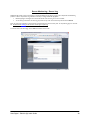
EN104L+(B) License Key - Entry for Web Admin Access
Upon fresh installation or change of NIC chip on the system requires new License Key entry for web admin access.
In order to obtain the CD Key, please contact Sans Digital with the MAC address of eth0.
MAC address of eth0 can be obtained by logging into the command line or by using the NAS-Finder utility. Access to command line can be
done by directly connecting the keyboard and monitor to the NAS.
For login details, please refer to “EN104L+(B) Log In”, in this manual.
Upon login, type “ifconfig” at the prompt and MAC address for eth0 can be obtained.
Sans Digital – EN104L+(B) Admin Guide
5
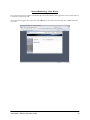
EN104L+(B) Log-In – Web Admin and Command Line
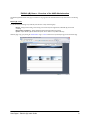
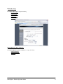
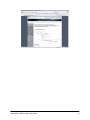
EN104L+(B) log-in via. Web admin
From internet explorer, such as IE 5.0 (and above) or Mozilla Firefox, type in the IP address of the NAS. Both http and https is supported.
Web admin log in page will come up, input as follows and select “enter”:
User ID: root
Password: 0000
Java runtime need to be installed on the system using the Web Admin.
The Java runtime is located in the Manual CD.
NOTE: If above password is not accepted, please contact Sans Digital for the password.
Sans Digital – EN104L+(B) Admin Guide
6
EN104L+(B) log-in via. Command line
Access to command line can be done by directly connecting the keyboard and monitor to the NAS.
To log-in steps from the command line:
Step 1:
Log in as “admin” by following username and password:
User ID: admin
Password: 111111
Step 2:
At the prompt, change user to super user by typing “su –“ (note there is a space between “u” and “-“)
Step 3:
At the prompt for password, type “0000”.
This will give you root user access to the NAS. Please note that changing the password for web admin access will also change the password for
the super user (username: root).
NOTE: If above password is not accepted, please contact Sans Digital for the support.
Options for web admin access (disable & enable http and telnet)
To disable or enable http, telnet and ssh service, you will need to log in via local log-in. Type the following command to control:
To disable web admin:
# mv /etc/xinetd.d/swat /root
# service xinetd restart
To enable Web services
# mv /root/swat /etc/xinetd.d
# service xinetd restart
To Disable telnet
# mv /etc/xinetd.d/telnet /root
# service xinetd restart
To Disable SSH
# service stop sshd
# chkconfig --level 345 sshd off
To Enable SSH
# chkconfig --level 345 sshd on
# service start sshd
Remarks:
If login as “admin” does not give you the access/permission enable or disable services with command line. Alternatively, you can also login as
“root”. However, it is not recommended due to security issues.
Sans Digital – EN104L+(B) Admin Guide
7
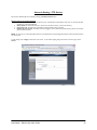
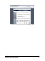
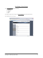
EN104L+(B) Home - Overview of the NAS Administration
The EN104L+(B) Administration Home page is accessible from any page within the Web Administration and provides access to the following
areas:
EN104L+(B) - Home
It is the Administration Main Page. It provides the portal entries for 3 major functional groups:
Manage – Manage network setting, volume setting, user account setup and configurations, and EN104L+(B) server status
monitoring
Backup Mirror and Restore – Manage Snapshot & NAS-to-NAS Failover/Mirroring Settings
Update – Update EN104L+(B) unit with the latest patch. Also for Reboot or input New License Key
Within any page of any group, clicking the “Administration” logo or “Home” button on the top will always bring you back to this Main page.
Sans Digital – EN104L+(B) Admin Guide
8
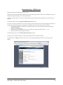
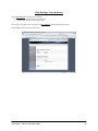
EN104L+(B) - Manage
Enter EN104L+(B) Manage to configure the following:
Server Configuration
Network Settings
Storage Management
User & Access
Server Monitoring
View Settings
EN104L+(B) Back Up, Mirror and Restore
Enter EN104L+(B) Back Up, Mirror and Restore to configure the following:
Snap Shot and Restore
Server Fail over & Mirror
View Settings
Sans Digital – EN104L+(B) Admin Guide
9
EN104L+(B) - Update
Enter EN104L+(B) Update to apply patches and updates for the product.
Sans Digital – EN104L+(B) Admin Guide
10
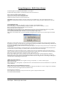
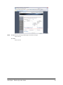
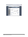
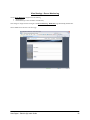
Server Configuration – General Settings
Enter basic server information here such as server name, date, time and language. EN104L+(B) records the date and time of events, files and
folders based on the system date & time set on this page.
Server Name
Enter a unique name to identify the EN104L+(B) server. Up to 15 alphanumeric characters (without spaces) are allowed for the server name.
By default, it is named: EN104L+(B).
Server Description
Enter a description of up to 50 alphanumeric characters for this EN104L+(B) to help identifying its use. This is an optional field.
Date
Enter the system date in each appropriate field in the mm/dd/yyyy format. For example, you would enter 04 / 19 / 2002 for April 19, 2002.
Time
Enter the system time in the 24-hour format. Indicate the hour, minutes & seconds in the hh:mm:ss format.
Time Zone
Select the time zone from the drop-down list. The default setting is America/Los_Angeles (US/Pacific Standard Time).
Language
The “Language” is referred to the language used on the client’s OS. It will not affect the language use in for the Web Admin GUI. The default
language is US English. If you wish to support a different language, select the language from the drop-down list. This multiple language setting
allows users to store and retrieve file and directory names that are in the selected language and US English.
Note: You must re-boot the server after changing language to take effect.
Time Sync by NTP
The “Time Sync by NTP” service allows EN104L+(B) to synchronize the date and time information from the NTP server. It is especially
important for Microsoft Domain environment as the connection will be rejected.
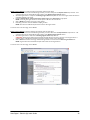
To synchronize with NTP (Network Time Protocol) Server:
1.
2.
3.
Select the radio button for Server and Client
Select the Stratum Server. If the server is not in the list, add the name of the server and select Add.
To delete existing NTP server address, select from the NTP Server List drop down box, select Delete.
To provide NTP Sync Service to attached clients:
1.
2.
Select the radio button for Server and Client
Enter the Network Address and Subnet Mask, and click Add.
To apply changes, click on Apply at the bottom of the screen. To return to the home page, click on Cancel.
Sans Digital – EN104L+(B) Admin Guide
11
Sans Digital – EN104L+(B) Admin Guide
12
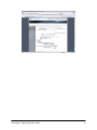
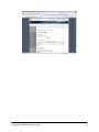
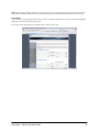
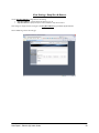
Server Config – Password Change
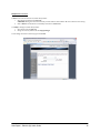
This is a page for changing the password of the user that log-in. To change your log-in password, enter the following information:
Current Password
Enter your current log-in password in this field which appears in asterisks for security purposes. By default, the “root” account’s password is:
0000
New Password
Enter the new password between six(6) to eight(8) alphanumeric characters. Non-alphanumeric characters such as – ) # ( * will not be
accepted. The password is case-sensitive and appears in asterisks for security purposes.
Confirm New Password
Re-enter the new password exactly as you entered it in the previous field to verify password accuracy. The password is case-sensitive and
appears in asterisks for security purposes.
CAUTION: Be sure to record your password in a safe place. If you have forgotten your password, you are required to re-install the
EN104L+(B) OS and will lose all data and configuration settings.
Once you have entered all the appropriate information, click on Apply at the bottom of the page to apply the changes. To exit without
applying changes and return to the home page, click on Cancel.
Sans Digital – EN104L+(B) Admin Guide
13
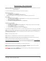
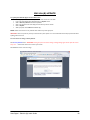
Server Configuration – Restart & Shutdown
This is a page for Restart or Shutdown the EN104L+(B) unit. It may be necessary to restart EN104L+(B) after system changes, upgrades, or
errors.
NOTE: Notify all logged-in users to log out before beginning EN104L+(B) to restart or shutdown, or the unsaved data will be lose and result
is errors.
Restart Now
Click on Restart Now to immediately shut down and reboot EN104L+(B). To avoid errors, you will be asked to confirm your request before
EN104L+(B) is restarted.
Shutdown Now
To completely power down EN104L+(B), click on Shutdown Now. The NAS will start its shut down process and turn off. To avoid errors,
you will be asked to confirm your request before EN104L+(B) is Shutdown.
Remark:
•
•
You can also use the NAS-Finder Utility to power off.
To force a hardware shut down, press the power button for more than four seconds and it will shut down immediately.
To exit without restarting or shutting down the NAS and return to the home page, click on Cancel.
Sans Digital – EN104L+(B) Admin Guide
14
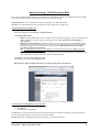
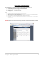
Network Settings: TCP/IP Setting for NICs
This is a page for configuring Multiple Gigabit ports for the EN104L+(B). The EN104L+(B) is equipped with 2 Gigabit ports. Additional Gigabit
ports can be added to increase performance. All of the Gigabit ports are configured in this page.
Assigned Port Pool is a list of the Network Ports assigned with settings. It can be DHCP, SFM or Static.
Port Pool is a list of the Network Ports where the settings have not been assigned and are available to use.
Configuring TCP/IP for the Gigabit Port
Select a desired Gigabit port from Port Pool or Assigned Port Pool.
Select DHCP, SFM and Static.
•
•
•
DHCP setting allows EN104L+(B) to receive an IP address from the DHCP sever existing in the network. Normally DHCP IP
address is only used for temporary setting to easily configure on network. For continued use, static IP address is
recommended.
SFM (Server Fail-over & Mirror) is a dedicated port(s) that is used to connect primary and secondary EN104L+(B) units
for heart-beat, data mirroring, and synchronization. This port can be used to transfer data to/from network attached clients,
but strongly not suggested to do so. A dedicated port for SFM is preferred. SFM required separate license and it is
currently only support in selected model.
Note: To configure SFM port, simply select the available port, click on SFM radio button and click on Apply. No TCP/IP
information is need for SFM port configuration.
Static IP setting allows EN104L+(B) to manually set an IP address to fit the existing network setting. You will need to provide
a free, unique IP address, Net Mask (Subnet Mask), Broadcast and Default Gateway.
Select Apply to confirm the setting or Cancel to go back.
Configured port will be listed under Assigned Port Pool.
Note: Change or Assign the Network Port setting will required reboot before it take effective.
To remove a port from Assigned Port Pool to Port Pool
•
•
•
Select a desired Gigabit port from Assigned Port Pool.
Select Remove.
Port will be listed under Port Pool.
The blink feature is provided to identify the physical port. The selected Network Port’s LED will start blinking to identify the physical port.
To exit without applying changes and return to the home page, click on Cancel.
Remarks: NIC Port #0 in the EN104L+(B) OS is labeled as NIC Port #1 on the Physical Hardware.
Sans Digital – EN104L+(B) Admin Guide
15
Network Setting – Port Bonding
Up to 4 Gigabit ports may be bonded using one of seven different bonding methods. Bonded ports provide higher throughput as well as
different level of fail-over.
Note: All bonded ports use the IP address and MAC address of the first port in the bond.
Bonded Port Pool lists the current team of bonding. It lists the Team#, IP Address and MAC address.
Unbonded Port Pool lists the available ports for bonding.
To bond ports
•
•
•
•
From the Unbonded Port Pool, select the desired ports to bond.
From the Bond Type, select the desired bonding method.
Select Bond Ports.
Ports will now show as a team, under Bonded Ports Pool.
NOTE: IP addresses for SFM ports are assigned internally. Therefore, instead of an IP address, you will only see “SFM” under IP address
section.
To remove bond
•
•
From the Bonded Ports Pool, select the bonded team to remove.
Select Remove Bond.
Bonding Type:
1. Round-Robin
Round-Robin policy: Transmit in a sequential order from the first available slave through the last. This mode provides load
balancing and fault tolerance.
2. Active-Backup
Active-Backup policy: Only one slave in the bond is active. A different slave becomes active if, and only if, the active slave fails. The
bond's MAC address is externally visible on only one port (network adapter) to avoid confusing the switch. This mode provides
fault tolerance.
3. XOR Balancing
XOR Balancing policy: Transmit based on an logical formula [ ( source MAC address XOR destination MAC address) * modular
slave count ]. This selects the same slave for each destination MAC address. This mode provides load balancing and fault tolerance.
4. Broadcasting
Broadcasting policy: Transmits everything on all slave interfaces. This mode provides fault tolerance.
5. 802.3ad
IEEE 802.3ad or Dynamic Link Aggregation: Creates aggregation groups that share the same speed and duplex settings. Transmits
and receives on all slaves in the active aggregator. It is also known as “Trunking”
Requirement: A network switch that supports IEEE 802.3ad Dynamic Link Aggregation / Trunking, and the switch must be
configured to enable the “trunking” feature. An 802.3ad capable switch, but without configuring it will not work.
6. TLB
TLB or Adaptive Transmit Load Balancing: Channel bonding that does not require any special switch support. The outgoing
traffic is distributed according to the current load (computed relative to the speed) on each slave. Incoming traffic is received by the
current slave. If the receiving slave fails, another slave takes over the MAC address of the failed receiving slave.
7. ALB
Adaptive Load Balancing: TLB + Receive Load Balancing (RLB) for IPV4 traffic and does not require any special switch support.
The receive load balancing is achieved by ARP negotiation. The bonding driver intercepts the ARP Replies sent by the server on
their way out and overwrites the source hardware address with the unique hardware address of one of the slaves in the bond such
that different clients use different hardware addresses for the server.
Sans Digital – EN104L+(B) Admin Guide
16
Receive traffic from connections created by the server is also balanced. When the server sends an ARP Request the bonding driver
copies and saves the client's IP information from the ARP. When the ARP Reply arrives from the client, its hardware address is
retrieved and the bonding driver initiates an ARP reply to this client assigning it to one of the slaves in the bond. A problematic
outcome of using ARP negotiation for balancing is that each time that an ARP request is broadcasted it uses the hardware address of
the bond. Hence, clients learn the hardware address of the bond and the balancing of receive traffic collapses to the current salve.
This is handled by sending updates (ARP Replies) to all the clients with their assigned hardware address such that the traffic is
redistributed. Receive traffic is also redistributed when a new slave is added to the bond and when an inactive slave is re-activated.
The receive load is distributed sequentially (round robin) among the group of highest speed slaves in the bond.
When a link is reconnected or a new slave joins the bond, the receive traffic is redistributed among all active slaves in the bond by
initiating ARP Replies with the selected MAC address to each of the clients. The un-delay mode probe parameter must be set to a
value equal or greater than the switch's forwarding delay so that the ARP Replies sent to the clients will not be blocked by the
switch.
Sans Digital – EN104L+(B) Admin Guide
17
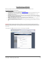
Network Settings - Microsoft Networking
By default, the CIFS/SMB service is enabled and given access to all the EN104L+(B) logical volumes. If you wish to disable this service and only
support other file systems, login to command line and type:
#service smb stop
To join Microsoft Workgroup, Domain, or Active Directory Service, follow the steps below:
Workgroup (for local user):
1.
Select Workgorup networking radio button
2.
Enter Workgroup name in the Workgroup or Domain Name field
Remarks: When a Windows client does not belong to a Domain or an ActiveDirectory, this client is a local user.
Domain (PDC):
1.
2.
3.
4.
Select Domain networking radio button
Enter the domain name in the Workgroup or Domain Name field. For domain networking, a Primary Domain Controller
(PDC) must be available on your network
Enter the name of the PDC in the Controller field
Enter account name in the Account field and password in the Password field
Active Directory Service (ADS):
1.
2.
3.
4.
Select ADS networking radio button
Enter the domain name in the Workgroup or Domain Name field. For ADS networking, an Active Directory Service (ADS)
must be available in your network.
Enter the IP address of the ADS server in the Controller field
Enter account name in the Account field and password in the Password field
To apply changes, click on Apply at the bottom of the screen. To exit without applying changes and return to the home page, click on Cancel
NOTE-1: Synchronizing with PDC or ADS will place all users and user groups in the PDC, or ADS server into the EN104L+(B). When access
to EN104L+(B) is attempted by either PDC or ADS users, EN104L+(B) will communicate with PDC or ADS server to authenticate the user
and pass through the proper permission.
NOTE-2: It is either PDC or ADS but not both
NOTE-3: With PDC, it is the Domain name to be entered. With ADS, it is the IP of the AD Server to be entered.
NOTE-4: In the case that synchronization to PDC or ADS fails, reset the EN104L+(B) account from the PDC or ADS server and retry.
Sometimes, resetting the administrator’s password also resolves the synchronization problem.
An other possible reason for the failure would be due to system time for EN104L+(B) and ADS Server are different. Time for EN104L+(B)
and ADS server must be the same down to the minute. If that is not the case, please use the NTP function to sync the time between the
NAS and the ADS Server.
Lastly, check your input for domain name, server IP address (or name for PDC), UID and password.
NOTE-5: EN104L+(B) seeks and lists users and groups in the order of Local, NIS, and ADS/PDC. In the event where you have UID
duplicated, above order will be used to list and accept duplicated users and groups.
CAUTION: When using SFM configuration, ENABLE ADS synchronization before turning on SFM. If ADS synchronization should require
disabling, DISABLE SFM before disabling ADS synchronization.
Sans Digital – EN104L+(B) Admin Guide
18
Sans Digital – EN104L+(B) Admin Guide
19
Network Settings - UNIX Networking
In order to allow UNIX clients to access EN104L+(B) logical volumes, NFS (Network File System) service must be enabled by checking the
Enable NFS service check box.
Synchronizing with NIS server will place all the users and user groups stored in the NIS server as local users and local user groups into
EN104L+(B). The NAS will communicate with the NIS server to update the user and user group list. In addition, any access attempts made by
the NIS users to the NAS logical volume will be authenticated by the UID and password stored in the NIS server.
To synchronize with Network Information Service (NIS)
1.
2.
3.
4.
Check Enable NFS service check box
Check Enable NIS service check box
Enter the domain name in the NIS Domain Name field
Enter the NIS server name in the NIS Server Name field
To apply changes, click on Apply at the bottom of the screen. To exit without applying changes and return to the home page, click on
Cancel.
NOTE: EN104L+(B) seeks and lists users and groups in the order of Local, NIS, and ADS/PDC. In the event where you have UID
duplicated, above order will be used to list and accept duplicated users and groups.
CAUTION: When using SFM configuration, ENABLE NIS synchronization before turning on SFM. If NIS synchronization should require
disabling, DISABLE SFM before disabling NIS synchronization.
Sans Digital – EN104L+(B) Admin Guide
20
Network Settings - Apple Networking
In order allow Apple clients to access EN104L+(B) logical volumes, AFP service must be enabled by clicking on the Enable AFP Service
check box. AFP service will allow NAS local users and user groups and/or NIS users and user groups to access EN104L+(B) logical volumes.
To apply changes, click on Apply at the bottom of the screen. To exit without applying changes and return to the home page, click on
Cancel.
Note: Mac/Apple client belongs to “local user” (workgroup) category.
Note: Mac/Apple clients can access the NAS shares via SMB/CIFS or AFP protocol. It is your own preference to pick which protocol that
works for the best.
Sans Digital – EN104L+(B) Admin Guide
21
Network Setting – DHCP Service
DHCP service on EN104L+(B) can be used to quickly assign IP addresses to the network attached clients. In other words, now the NAS acts
like a DHCP server.
To enable service, check Enable DHCP check box
1.
2.
3.
4.
5.
Assign IP address range
Enter subnet to assign to the DHCP Clients
Enter gateway to assign to the DHCP Clients
Enter addresses for primary and/or secondary DNS. Entering both primary and secondary is not absolutely required.
For client IP address renewal, input appropriate value in the fields for Day, Hour, Min, and Sec.
NOTE: The DHCP service on EN104L+(B) is not intended to replace the DHCP server of Active Directory Service, Primary Domain
Controller or Network Information Service. This feature is to provide convenient management of local clients that are not part of
aforementioned network infrastructure.
To apply changes, click on Apply at the bottom of the screen. To exit without applying changes and return to the home page, click on
Cancel.
Sans Digital – EN104L+(B) Admin Guide
22
Network Setting – FTP Service
FTP service for EN104L+(B) can be enabled by selecting the Enable FTP Service box.
Following features are supported by FTP
1.
2.
3.
4.
Allow anonymous access: This feature allows any user, with FTP feature and IP address of the server, to read from the public
FTP directory created in EN104L+(B).
Allow upload: This feature allows any user, with access to the public directory, to write to the directory.
Anonymous root: This selects the Logical Volume, which the public directory will reside.
Disallow directory browse: This feature prevents any logged in users to browse beyond that directory that the user has been
given permission to access.
NOTE: For security, it is recommended that FTP service is provided behind a properly configured firewall to minimize unwanted intrusion
over the network.
To apply changes, click on Apply at the bottom of the screen. To exit without applying changes and return to the home page, click on
Cancel.
Sans Digital – EN104L+(B) Admin Guide
23
Network Setting – iSCSI Service
EN104L+(B) is equipped with iSCSI initiator and target services.
iSCSI initiator allow to attach multiple iSCSI target devices and convert them to Logical Volumes for client access. iSCSI target devices may be
locally resident within EN104L+(B) or from a remote/external system.
iSCSI target is doing the opposite, it converts part of the physical capacity into iSCSI target volume and present to the network clients as if a
local disk.
To enable the initiator service, check the Enable iSCSI Initiator Service check box.
For initiator name, either use the default name or rename it following the rules for iSCSI node names. Rules for building iSCSI node names are
described in the iSCSI specification and the “String Profile for iSCSI Names” internet draft. In summary the rules are as follows:
•
•
•
•
Node names are encoded in the UTF8 character set. Note the initiator service does not support UCS-4 characters. RFC 2044
describes UTF8 encoding.
Node names are 223 bytes or less
Node names may contain alphabetic characters (a to z), numbers (0 to 9) and three special characters: ‘.’, ‘-‘, and ‘:’.
Uppercase characters are always mapped to lowercase.
To enable the target service, check the Enable iSCSI Target Service check box.
For target name, use the default name given, or, follow the requirements described in the iSCSI specification.
To apply changes, click on Apply at the bottom of the screen. To exit without applying changes and return to the home page, click on
Cancel.
Sans Digital – EN104L+(B) Admin Guide
24
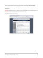
Storage Management – RAID Volume Manager
The EN104L+(B) LB model equipped with build-in RAID 0, 1, 5, 6 support.
The RAID Volume Manager interface in the Web Administrator allows the administrator to:
Discover disk drives available for RAID configuration.
Create, remove, rebuild, and expand multiple RAID volumes.
Assign and remove hot spare to/from existing RAID volume.
Identify external SATA hard disk drive used for backup purpose.
CAUTION: external SATA hard disk drive must not be configured as part of RAID volume. Since external SATA hard disk drive is
recognized as a standard SATA hard disk drive, administrator must keep in mind of its capacity and model to differentiate from other disk
drives.
Creating RAID Volume(s):
Select available disks from Disk Pool. These disks are ready to be assigned to the desired RAID volume.
Select desired RAID type. Only possible RAID types will appear as selection option. Choose from RAID 0, 1, 5, and 10
Refer to Storage Management Overview for RAID volume type definitions.
Select desired stripe size for the RAID volume.
Select Rebuild Speed from High, Medium or Low. Rebuild speed sets the priority of resource allocation between data serving and RAID
volume rebuilding. High setting will put rebuilding process on higher priority than data serving to clients’ request.
Select CREATE RAID & ASSIGN SPARE. Same button is used to create RAID or assign hot spare.
When asked to confirm RAID creation, select YES. CAUTION: Creating RAID volume will erase data on the disk(s) assigned to the RAID
volume
RAID will start to build. RAID creation process can be verified by web administrator page displaying RV in the RV Pool while assigned disks
from Disk Pool are removed. The status will show as (clean, degraded, recovering xx% complete)*. Software RAID Manager will refresh every
30 seconds to show updated progress and status of RAID, hot spare and disk.
RV is identified with RAID type, RAID volume ID#, total capacity, disks assigned to the RV (RV member), Remove RV option and RAID volume
consistency check.
To help with RV member identification to associate disk ID shown on the web administrator and physical disk, disk blink button (blue button
next to disk status) is provided. Clicking on it will blink the LED on physical disk until the button is clicked again.
After RAID volume is created, status changes to (OK)*. In addition, Remove option for individual disk assigned to the RV (RV member) is
offered. CAUTION: Voluntary removal of properly functioning disk assigned to a RAID volume is not recommended. Such action will place
RAID volume in degraded mode and failure of another RV member can result in fatal error.
Remove option for RAID volume is used to completely remove the RAID volume and replace its members (disks) back to Disk Pool.
Remove option for RV members removes the disk from the RV and places it in the Disk Pool. This option should only be used when the
administrator wishes to re-assign the disk to another RAID volume without such action causing fatal error to the existing RV. RAID signature
on the RV member is erased during the removal process.
*RAID Volume Status Definition:
RAID build, Rebuilding with hot spare: (clean, degraded, recovering, xx% completed). xx = number to indicate progress.
RAID in good status: (OK)
RAID in degraded mode: (clean, degraded) + Inoperable status next to the disk that failed & removed from the RAID volume. Inoperable disk
is shown in Disk Pool.
Adding & Removing Hot Spare/RAID Volume Expansion:
Adding a hot spare requires selection of existing RV and assigning an available disk in the Disk Pool. Hot spare is assigned to a RV individually;
as a result, RV without hot spare assigned cannot have automatic recovery.
Select existing RV from the RV Pool
Select available disk from the Disk Pool. Hot spare must be same or greater is capacity than the RV member.
Select CREATE RAID & ADD SPARE.
Sans Digital – EN104L+(B) Admin Guide
25
When asked to confirm adding hot spare, select YES
Hot spare is added and is identified as “(Spare)” assigned next to a RV member.
Hot spare can also be used to expand the capacity of RAID volume. Selecting EXPAND button will execute the process. CAUTION: RAID
volume expansion process will take much longer time than RAID volume creation or rebuilding. It is recommended to only execute this task
when no clients are accessing the RAID volume.
To remove hot spare from the RV, select the hot spare and REMOVE next to the spare. Confirm removal of spare by selection YES to
confirmation. Hot spare is assigned to the Disk Pool as available disk.
RAID Volume Rebuilding:
In the event a RV member becomes fatal or intermittent, RV will be identified as Degraded. Degraded RV can sustain normal operation but it
will become fatal if another member of that RV fails. RV with hot spare will automatically repair itself by replacing the fatal RV member with
the hot spare.
RV in degraded mode is being rebuilt by automatically adding the hot spare as the RV member while fatal RV member is placed in Disk Pool
with INOPERABLE status.
Fatal RV member, now in individual disk state, can be removed from the system and replaced with a new disk drive. CAUTION: It is highly
recommended that replacement disk is the same make, model, capacity and version as the original disk. Furthermore, replacement disk must
not have any RAID signature as a result of having been a member of another RAID volume. Not following this recommendation can result in
unstable RAID volume and loss of data.
Replacement disk drive will be placed in the Disk Pool, ready to be assigned as hot spare to the RV, or, used to create another RAID volume.
If RV did not have hot spare assigned, following steps can be used to rebuild the degraded RV.
Pull out the fatal RV member from the Disk Pool.
Insert the replacement disk drive.
Select the replacement disk drive, or any other available drive in the Disk Pool.
Select the degraded RV.
Select CREATE RAID & ADD SPARE.
Confirm adding hot spare by selecting YES.
Degraded RV will start to rebuild using the newly added spare as replacement of fatal RV member.
After desired RAID volume has been created, go to Volume Group Manager to convert the RV’s into Physical Volume (PV) so as to prepare for
Logical Volume (LV) assignment. Please go to Volume Group Manager and Logical Volume Manager in this manual for details.
Removing RAID Volume:
Removing the RAID volume can be done voluntarily as long as Physical Volume (PV) is not assigned to the RV. This is to prevent accidental
removal of RV that is likely configured and being used as Logical Volume (LV). LV is likely to contain valuable data and it cannot be recovered
once the RV is removed.
To remove RV, select RV from the RV Pool and select REMOVE.
If PV is assigned to the RV, it is identified by display “Used by PVx” where “x” is a PV ID #.
PV must first be removed from RV at Volume Group Manager, return back to Software RAID Manager, and recommence RV removal process.
Confirm RV removal by confirming with YES.
RV will be removed and all RV members will be assigned to the Disk Pool as available disks.
CAUTION: Removing RV will cause permanent loss of data in all the LV’s that were assigned to the RV.
During any steps described in this section, clicking on Cancel will discard the changes and return to the Administration Home.
Sans Digital – EN104L+(B) Admin Guide
26
Sans Digital – EN104L+(B) Admin Guide
27
Storage Management – iSCSI Initiator Manager
iSCSI Initiator Manager is used to discover and connect to the iSCSI target devices internal or external to the AccuNAS system. Connecting to
the iSCSI target device offers following benefits:
•
•
•
•
Expand storage volume when adding more disk drives within the AccuNAS is not possible.
Use EN104L+(B) as a gateway to manage Logical Volumes residing in both internal and/or external to AccuNAS system.
Aggregates multiple iSCSI target devices as a single, large, storage space
Provides an alternative to Fibre Channel or SCSI bus to connect to external storage subsystem
To discover available iSCSI target portals and iSCSI target devices
1.
2.
3.
4.
Input IP address and Port number (3260 is default) of the system that contains iSCSI target devices
If Challenge Handshake Authentication Protocol (CHAP) is applied to the iSCSI target devices, input the user ID and password for
Outgoing and Incoming. Outgoing is used when the system connecting TO the iSCSI target device requires user ID and password.
Incoming is to authenticate the system where iSCSI target device resides. In the case of incoming authentication, it is the iSCSI
target device system authenticating TO the initiator system.
Click on Discovery and list of iSCSI target devices will displayed on the List field
To remove any iSCSI target device from the List, click on the device and select Remove button.
Connecting in and disconnecting iSCSI target devices
1.
2.
3.
4.
Select desired iSCSI target device to connect to
if CHAP is applied to the selected iSCSI target device, input appropriate Outgoing and Incoming user ID and password
Select Log In button to connect.
To disconnect, select the desired iSCSI target device then click on Log Out button
PV/RV Information
This section shows the list of iSCSI target devices that are available to connect and those that are already connected with the initiator. PV
Pool shows the iSCSI target devices that were connected and became part of Physical Volume list. RV Pool shows the available iSCSI target
devices that have not been connected.
NOTE: More information on RV and PV located under Storage Management – Volume Group Manager sections.
Sans Digital – EN104L+(B) Admin Guide
28
Storage Management – Volume Group Manager
Volume Group Manager is to write the NAS signature to the RAID volume (RV – raw volume) which turns a RV into PV. When Physical
Volume (PV) is created, it is ready to be converted into Logical Volume (LV) for file serving.
Volume Group Types/Definitions
•
•
•
Raw Volume (RV) is the RAID volume(s), or external iSCSI target(s) that are unformatted. The next step is to convert RV into
PV.
Physical Volume (PV) is a volume that is ready to be partitioned and formatted with a file system, and converted into Logical
Volume (LV).
Note: PV is automatically formatted and converted to LV having the equal capacity as the PV. In the case of converting iSCSI target
device or SCSI device to PV, manual creation of LV is required.
Logical Volume (LV) is a volume/share/folder that has been partitioned and formatted and ready to be used by attached clients.
Volume Group Manager features
•
•
•
•
Converts RV to PV
Add RV to PV, thus, creating Expanded PV
Remove PV to RV Pool
Remove or Replace RV that’s been added to PV
Creating PV
Creating PV is to convert the RV from the RV Pool to PV. Once RV is converted to PV, it is ready to be converted to Logical Volume (LV).
Conversion from PV to LV means PV is formatted and ready to be used by network clients attached to EN104L+(B).
To create PV, select the desired RV and click on Create PV.
Removing PV
PV’s in the PV Pool or Expanded PV Pool can be removed and converted into RV.
To remove PV, select the desired PV from the PV Pool, or Expanded PV Pool, and click on Remove PV.
Adding RV to PV
RV’s in the RV Pool can be added to the PV in the PV Pool to expand the capacity of the original PV, or, insert more LV’s.
To add the RV to the PV, select the desired RV and the PV and click on Add RV to PV. This process adds RV to the existing PV, thus,
creating the Expanded PV. Now, the added RV is named as PV.
NOTE: RV’s that were iSCSI target device or SCSI device require manual conversion into LV to be usable by the attached clients.
To separate the PV from Expanded PV
To remove the PV that’s been added to the PV, click on the PV from the Expanded PV Pool and click on Remove PV from PV. This process
removes the PV from the Expanded PV, converts the PV to RV and places it in the RV Pool as an RV.
Physical Volume Expansion may be used to combine multiple PV’s to create a single, large PV. This process can be useful when combining
multiple PV’s belonging to different RAID controller cards.
To replace the PV in the Expanded PV with another RV
To replace a PV belonging to Expanded PV with another RV, all necessary volumes can be selected at once rather than removing first, then,
adding next.
Sans Digital – EN104L+(B) Admin Guide
29
Select the PV belonging to Expanded PV, select the RV you wish to replace the PV selected, then click on Replace PV in Exp. PV.
Remarks: By default, once the PV is created, the NAS automatically converts the ENTIRE capacity of PV into LV with XFS file system. If
other setting is desire, please use the “Logical Volume Manager” to delete the existing volume, and re-create volume(s) in different size and
different file system.
CAUTION: Deleting Physical Volume will result in deletion of any Logical Volume and Snapshot Volume associated with the Physical Volume.
CAUTION: Removing PV, Separating PV, or Replacing PV will cause the PV to lose its data.
Selecting Cancel will take you back to the Home page.
Sans Digital – EN104L+(B) Admin Guide
30
Storage Management - Logical Volume Manager
Logical Volume (LV) is a formatted storage volume in PV, which can be shared by network clients attached to EN104L+(B). In other words,
LV is the network share/folder that can be shared and accessed by network clients.
Note: By default, once the PV is created, the NAS automatically converts the ENTIRE capacity of PV into LV with XFS file system. If other
setting is desired, please delete the existing volume first, and re-create volume(s) in different size and different file system.
Note: by default, all users are given access to a logical volume. To assign exclusive access to specific users or user groups, go to the User and
Access section.
Functions of Logical Volume Manager are:
1.
2.
3.
4.
Create Logical Volume
Designate file system or iSCSI to Logical Volume
Modify Logical Volume
Delete Logical Volume
Create a Logical volume: To create a new Logical Volume, follow the steps below:
1.
2.
3.
4.
5.
6.
7.
Select a Physical Volume with available space from the Physical Volume drop-down list.
Enter a unique name in the Volume Name field using up to 15 alphanumeric characters with no spaces.
NOTE: Do not use identical names for Logical Volumes, even if they belong to different Physical Volumes.
If it is beneficial to add a description of this Logical Volume to help identify its use, enter that description in the Volume
Description field using up to 50 alphanumeric characters. This is an optional field.
Enter the storage size of the Logical Volume in Megabytes in the Volume Size field, keeping in mind the amount of available space.
Designate the Logical Volume to select a file system of: ReiserFS, XFS, or iSCSI(target).
Remarks: if SFM (NAS Mirroring and Failover) is intended to be used, please select ReiserFS for it has better resistant to sudden
power lost or sudden shutdown for whatever reasons.
Click on Create at the bottom of the page.
Repeat the above steps to create additional logical volumes.
To exit and return to the home page, click on Cancel.
Remarks on iSCSI Target Volume:
If iSCSI target volume is selected instead of XFS or RerserFS, please pay extra attentions to following points:
(1)
Do Not use underscore “_“ in the iSCSI target volume name.
(2)
Regardless how many iSCSI target volumes you have on the NAS, they are all using port 3260. So from the initiator side, you only
need to specify one single IP plus port 3260, and all the iSCSI volumes on the NAS will be visible. The permission to access each
iSCSI target volume is controlled by the iSCSI ACL section.
(3)
If use Microsoft iSCSI initiator to connect to the iSCSI target volume on the NAS, make sure you define the iSCSI volume as “basic
disk” under Windows Disk-Manager, if you define the iSCSI volume as “dynamic disk”, it will not survive the system reboot/restart
and will require “reactivate” upon reboot.
(4)
If a successful connection has been established between Microsoft iSCSI initiator and the iSCSI target volume on the NAS, but later
on, you decide to change the IP address on the NAS, then, you must follow the procedure below to re-established the iSCSI
connection:
(a)
(b)
(c)
(d)
(e)
(f)
Log-off the target from MS iSCSI Initiator
Remove the NAS IP from the “Discovery Æ Target Portal” from MS iSCSI Initiator
From AccuNAS, go to: “Network Setting” Æ “TCP/IP Setting” to change the IP
Go to “Network Setting” Æ “iSCSI Service”
First, un-check “iSCSI Target Service”, click “Apply”
Then, re-check “iSCSI Target Service”, click “Apply”
Now, go back to MS iSCSI initiator, from the “Discovery Æ Target Portal”, Enter the new IP address of the NAS with
port 3260.
Now re-do the target logon.
Fail to follow these steps may cause “authentication” failure after changing the IP of the NAS.
Sans Digital – EN104L+(B) Admin Guide
31
Modify a Logical Volume: To modify an existing Logical Volume, follow the steps below:
1.
2.
3.
4.
5.
Select the Physical Volume that contains the Logical Volume you wish to modify from the Physical Volume drop-down list. A list
of Logical Volumes for the selected Physical Volume appears in the Existing Logical Volume window.
Select the Logical Volume to modify from the Existing Logical Volume drop-down list. The current Logical Volume information is
immediately displayed on the screen.
Modify the Volume Name, Volume Description, Volume Type and/or Volume Size, as appropriate.
NOTE: Converting the Logical Volume from one file system to the other will erase the data.
Click on Modify at the bottom of the page to apply changes.
Most likely, you need to restart the NAS after modifying a volume.
NOTE: Size cannot be modified if Snapshot Volume exists for that Logical Volume.
To exit and return to the home page, click on Cancel.
Delete a Logical Volume: To delete an existing Logical Volume, follow the steps below:
1.
2.
3.
Select the Physical Volume that contains the Logical Volume you wish to delete from the Physical Volume drop-down list. A list
of Logical Volumes for the selected Physical Volume appears in the Existing Logical Volume window.
Select the Logical Volume to delete from the Existing Logical Volume drop-down list.
CAUTION: Deleting Logical Volumes cannot be undone and data will be lost. Be sure to select the correct Logical Volume. If
Snapshot Volume is associated with selected Logical Volume, Snapshot Volume must be deleted first.
Click on Delete at the bottom of the page. The selected Logical Volume is removed from the Select Logical Volume list.
NOTE: Logical Volume cannot be deleted if Snapshot Volume exists for that Logical Volume.
To exit and return to the home page, click on Cancel.
Sans Digital – EN104L+(B) Admin Guide
32
Storage Management - Format
Format a logical volume to erase all of its contents. Although it is not required, you can also change the logical volume name.
CAUTION: Formatting a physical volume cannot be undone and you will be asked to confirm your request. Be sure to move data you need
to save to another location before formatting the volume.
To format a logical volume, follow the steps below:
4.
5.
6.
Select the logical volume from the Logical Volume drop-down list.
If you wish to change the volume name (optional), enter a new name in the Enter New Name field using up to 15 alphanumeric
characters with no spaces.
Click on Format. The NAS immediately begins to format the selected logical volume.
To exit without formatting and return to the home page, click on Cancel.
Sans Digital – EN104L+(B) Admin Guide
33
User & Access - Local User Management
Local users are those user accounts that are created within EN104L+(B) manually and specifically for access to EN104L+(B) files and folders.
Once local users are created, they can be assigned to logical volumes as individual users or as part of a user group.
Note:
-
“Local users” are Windows clients who do not belong to a Windows Domain and Windows Active-Directory, and often, “local
users” are referred to as “Workgroup” users.
Mac/APF clients are defined as “local users”.
Create Local Users
To create local users, enter the following information for each user:
1.
2.
3.
4.
5.
6.
7.
User Name - Enter the first and last name of the user with a maximum of 25 characters.
Password - Enter a unique password for the above user between 6-8 alphanumeric characters without spaces. The password is
case-sensitive.
Confirm Password - Re-enter the password again to confirm entry.
Assign Home Directory - Select this option to provide a home directory for this user. A home directory is a private directory
that only the owner and administrator can see.
Logical Volume - Select the Logical Volume to store local user’s home directory.
Click on Create to add the user to the local user list.
Repeat the steps above to create additional local users.
To undo changes and return to the home page, click on Cancel.
NOTE: EN104L+(B) seeks and lists users and groups in the order of Local, NIS, and ADS/PDC. In the event where you have UID
duplicated, above order will be used to list and accept duplicated users and groups.
Access to User’s Home Directory
Home directory is a private directory for each local user. Home directory cannot be opened by other users other than the owner and the
administrator. Home directory can be accessed by using two methods:
1.
2.
Map to the Logical Volume Share that contains your home directory.
Access via. Web browser by typing in ftp://username@server name or IP address of the server
Sans Digital – EN104L+(B) Admin Guide
34
Modify/Delete Local Users
To delete a user from the local users’ list, follow the steps below:
1.
2.
Select the user to delete from the User List.
CAUTION: Deleting users cannot be undone and you will be asked to confirm deletion. Be sure to select the correct user(s).
Click on Delete. The selected user is immediately removed from the User List.
To modify an existing user, follow the steps below:
1.
2.
Select the user from the User List.
Change user name or password, and select Apply Changes.
To undo changes and return to the home page, click on Cancel.
Sans Digital – EN104L+(B) Admin Guide
35
User & Access - Local User Group Management
User groups are formed to easily manage a group of users and apply access levels to the entire group for specific logical volumes. The new user
groups you create will be available to assign to logical volumes on the Access Control – Microsoft and Access Control - Apple.
Create Local User Groups
To create a new local user group, follow the steps below:
1.
2.
3.
4.
5.
Enter a unique name for the user group in the Local User Group Name field, up to a maximum of 15 alphanumeric characters.
Click on Create. The new local user group appears on the Local Groups list.
To add users to the user group, select the group from the Local Groups list.
Select the user from the All Users list and click on Add. Multiple users can be selected using the Ctrl and Shift keys.
Repeat the steps above to create additional user groups.
To exit and return to the home pages, click on Cancel.
NOTE: EN104L+(B) seeks and lists users and groups in the order of Local, NIS, and ADS/PDC. In the event where you have UID
duplicated, above order will be used to list and accept duplicated users and groups.
Modify/Delete Local User Groups
To modify a user group, follow the steps below:
NOTE: To change the name of the user group, you must delete the existing user group and re-create with the desired name.
1.
Select the user group to modify from the Local Groups list. The members of the user group are immediately displayed in the
Group Users list.
2.
Add and/or remove a user by selecting the user from the All Users list and clicking on Add or selecting the user from the Group
Users list and clicking on Remove.
3.
Repeat the steps above until you have modified all necessary user groups.
To delete a user group, follow the steps below:
1.
2.
Select the user group to delete from the Local Groups list.
CAUTION: Deleting user groups cannot be undone and you will be asked to confirm deletion. Be sure to select the correct user
group(s).
Click on Delete. The selected user group is immediately removed from the Local Groups list.
To exit and return to the home page, click on Cancel.
Sans Digital – EN104L+(B) Admin Guide
36
User & Access - Access Control: Microsoft Windows
Once logical volumes have been created, users or user groups can be assigned to have access to specific logical volumes. By default, all users
are given access to a new logical volume. You can assign exclusive access rights to a logical volume to one user group or individual user.
Furthermore, you can specify an individual user, who is part of a user group, to have higher or lower access level than the rest of the group.
This section controls the access control at the directory level. For sub-directory and file level access control, user must assign them directly to
the sub-directory, or file, from the Microsoft Windows client.
Assign Access Control
To assign users and/or user groups access to a logical volume, follow the steps below:
1.
2.
3.
4.
5.
6.
Select the logical volume that you wish to give user access to from the Select Logical Volume drop-down list.
Select the users and/or user groups from the All Users list.
Select one of the following access levels:
•
Full Control – read, write, and delete file privileges to the selected logical volume
•
Read/Write – read and write files to the selected logical volume. Users will not be able to delete files.
•
Read Only – read privileges to the selected logical volume. Users will not be able to add new files, modify files or delete
files.
•
Deny – all access is denied to the selected logical volume for the user. This is necessary when you wish to give access to
a user group except for an individual user within that group. Any individual user within a user group can be assigned with
different access level from the rest of the user group by assigning a different access level to the individual user for the
logical volume. The individual user access level takes priority over the user group access level. User will not be able to
read, write or delete any files within the logical volume.
Click on Add.
To remove a user or user group from the logical volume, select them from the Assigned Users list and click on Remove.
Repeat steps 2 through 5 above to add or delete additional users and/or user groups to the logical volume.
To exit and return to the home page, click on Cancel.
Host IP Blocking
In addition to user level access control, you can specify host-level security. To add or delete an IP address, follow the steps below:
Adding an IP Address
1.
2.
3.
4.
Select the logical volume that you wish to give host access to from the Select Logical Volume drop-down list.
Enter IP address of the host in the Enter IP address field.
Click on Allow to allow host access or Deny to deny host access to the selected logical volume.
Click on Add.
Deleting an IP Address
1.
2.
3.
Select the logical volume where you wish to delete host access from the Select Logical Volume drop-down list.
Select the IP address from the IP Address drop down list.
Click on Delete.
To exit and return to the home page, click on Cancel.
NOTE: When IP address is added to the Allow list, those on the Allow list are the only host IP addresses that will be allowed to access the
Logical Volume. When IP address is added to the Deny list, those on the Deny list are the only host IP addresses that will be denied to access
the Logical Volume.
Sans Digital – EN104L+(B) Admin Guide
37
NOTE:
To stop CIFS service, please log into EN104L+(B) via. Command Line and type:
#service smb stop
To re-start:
#service smb start
Sans Digital – EN104L+(B) Admin Guide
38
User & Access - Access Control: UNIX
NOTE: Synchronizing EN104L+(B) with NIS does not automatically give NIS users the access to the Logical Volume. All Logical Volumes to
be accessed by NIS users must first be mounted by the host computer.
To add host access:
1.
2.
3.
4.
5.
Select the logical volume that you wish to give host access to from the Select Logical Volume drop-down list.
Type in the IP address of the UNIX host.
Select the mounting option. When adding each host to the logical volume, there are four levels of access that can be applied to the
host:
•
Root Squash – Any user logging in as “root” will be assigned a different user ID so that limited privilege of
read/write/delete is assigned to the logged-in user.
•
All Squash – Any user logging in will be assigned a different user ID so that limited privilege of read/write/delete is
assigned to the logged in user.
•
Read Only – Any user logging in can have read-only access.
•
Secure – Secure option limits the user that can mount to NFS file system to super users only (TCP/IP port #1024 and
below). If a third party application exists that allows non-super users to mount to the NFS file system, secure option
should be deselected.
Click on Add.
By default, Top directory permission is set to rwx/rwx/rwx. To modify, select desired combination of rwx permissions for
owner, group and other, and select Modify. Note: Sticky bit is used to allow only the root or the owner of the file to unlink or
rename the file. When disabled, anyone that has access to the directory can rename or unlink the file.
To delete the host:
1.
2.
Select the IP address from IP Address drop down box
Click on Delete.
To exit and return to the home page, click on Cancel.
NOTE:
•
•
•
Selecting Enable NFS Service under Network Settings enables global NFS access. Disabling this option disables NFS access
completely.
Unless NFS access is added with host IP address for each logical volume, NFS access for that logical volume is disabled. As a result,
drop down box of the NFS access for the logical volume share indicates Disabled as a default.
Unless each IP address is deleted manually, setting to Disabled for the logical volume share does NOT delete IP address(es).
Security Method for NFS Access:
EN104L+(B) implements standard UNIX security for NFS access. This means that the UNIX host that is added to the logical volume can mount
to the logical volume with assigned access privileges. Any user logging into the host is authenticated by the NIS (Network Information Service)
server or the UNIX host’s own security. After the user is logged into the host, he/she is able to access the logical volume on EN104L+(B) with
read/write/delete or read-only privilege, depending on the access privilege that was assigned to the host. Individual sub-directory created by the
user can be secured by applying 1) owner only, 2) user group that the user belongs to, or 3) everyone to the sub-directory.
Sans Digital – EN104L+(B) Admin Guide
39
Sans Digital – EN104L+(B) Admin Guide
40
User & Access - Access Control: Apple
Once logical volumes have been created, local, or NIS, users or user groups can be assigned to have access to specific logical volumes. By
default, all users are given access to a new logical volume. You can assign exclusive access rights to a logical volume to one user group or
individual user. Furthermore, you can specify an individual user, who is part of a user group, to have higher or lower access level than the rest
of the group.
This section controls the access control at the directory level. For sub-directory and file level access control, user must assign them directly to
the sub-directory, or file, from the host.
Assign Access Control
To assign users and/or user groups access to a logical volume, follow the steps below:
1.
2.
3.
4.
5.
6.
Select the logical volume that you wish to give user access to from the Select Logical Volume drop-down list.
Select the users and/or user groups from the All Users list.
Select one of the following access levels:
•
Allow – read, write, and delete file privileges to the selected logical volume
•
Read/Write – read and write files to the selected logical volume. Users will not be able to delete files.
•
Read Only – read privileges to the selected logical volume. Users will not be able to add new files, modify files or delete
files.
•
Deny – all access is denied to the selected logical volume for the user. This is necessary when you wish to give access to
a user group except for an individual user within that group. Any individual user within a user group can be assigned with
different access level from the rest of the user group by assigning a different access level to the individual user for the
logical volume. The individual user access level takes priority over the user group access level. User will not be able to
read, write or delete any files within the logical volume.
Click on Add.
To remove a user or user group from the logical volume, select them from the Assigned Users list and click on Remove.
Repeat steps 2 through 5 above to add or delete additional users and/or user groups to the logical volume.
In addition to above options, following options can be set when necessary:
•
•
•
•
•
•
•
•
Casefold option: Casefold option handles how casenames should be mangled. Default Setting is NONE.
o
tolower-: Lower cases names in both directions.
o
toupper-: Upper cases names in both directions.
o
xlatelower-: Client sees lower case, server sees upper case.
o
xlateupper- Client sees upper case, server sees lower case.
mswindows: Forces filename restrictions imposed by MS WinXX, and invokes the MS default codepage (iso8859-1) if one is not
already specified.
prodos: Provides compatbility with Apple II clients
nohex:
Disables :hex translations for anything except for dot files. This option makes the / character illegal.
crlf conversion:
Enables crlf translation for TEXT files.
usedots: Don’t do :hex translation for dot files. This makes all files such as .Parent, .Apple* illegal. Dot files created on the server
side will be invisible to the client.
read only: Specifies the share as being read only for all users.
limitsize: Hack for older Macintoshes using newer Appleshare clients to limit the disk size reporting to 2 GB.
To exit and return to the home page, click on Close.
Note: Mac/Apple clients can access the NAS share via SMB/CIFS or AFP/AppleTalk. It is up to the end user to pick whichever method that
he/she feels comfortable for his/her applications.
Sans Digital – EN104L+(B) Admin Guide
41
Sans Digital – EN104L+(B) Admin Guide
42
User & Access – iSCSI Target
User and Access control can be applied to iSCSI target device with User ID & Password as well as by Host IP of the client.
•
•
•
Global Users define the access control for all iSCSI target devices within EN104L+(B). Having access as a global user allows this
user to scan and view all iSCSI target devices in the system.
Target Users define the access control for individual iSCSI target device. Each target device may have different user ID and
password, thus, user may not have access to all of the target devices in the system.
Host IP Blocking controls access to each iSCSI target device by allowing or disallowing Host IP addresses of the client. This
feature is a subset of Target Users, thus, each iSCSI target device must have its own Host IP Blocking list.
To Create User:
There are two ways to control access at the user level:
1.
2.
3.
Incoming: Incoming user and password controls any users that are trying to access the iSCSI target device from another host in the
network. This is the case for both Global Users and Target Users.
Outgoing: Outgoing user and password controls the authenticity of iSCSI target device to the inquiring user. This is to certify to
the incoming user that the system that they’re trying to access is indeed the system they’ve intended to access.
NOTE: This feature is not supported by all iSCSI initiators available. Please refer to your iSCSI initiator manual for details.
Incoming and Outgoing user applies to both Global User and Target User.
NOTE: Only 1 user ID and password is used for Outgoing user.
Global User:
1.
1.
2.
3.
4.
Input user name
Input password
Confirm the password
Click on Add. This will create the user and add the user to the User List
Same steps are used for both Incoming and Outgoing Users
Target User:
1.
2.
3.
4.
5.
6.
Select the desired LV from the Select Logical Volume drop down bar
Input user name
Input password
Confirm password
Click on Add. This will create the user and add the user to the User List
Same steps are used for both Incoming and Outgoing Users
NOTE:
•
•
Length of the password and character requirements depend on iSCSI Initiator used. Refer to your iSCSI Initiator manual for details.
User list for iSCSI target devices, both Global and Target, is separate from the User list that belongs to Local, NIS or, ADS.
To Delete User:
For both Global and Target, Incoming and Outgoing, users, select the desired user from the User List and select Delete.
Host IP Blocking:
In addition to user ID and password access control, you can specify host IP of the client for access control. To add or delete an IP address,
follow the steps below:
Adding an IP Address
1.
2.
3.
Enter IP address of the host in the Enter IP address field.
Click on Allow to allow host access or Deny to deny host access to EN104L+(B) NSS system
Click on Add.
Deleting an IP Address
4.
5.
Select the IP address from the IP Address drop down list.
Click on Delete.
To exit and return to the home page, click on Cancel.
Sans Digital – EN104L+(B) Admin Guide
43
NOTE: When IP address is added to the Allow list, those on the Allow list are the only host IP addresses that will be allowed to the target.
When IP address is added to the Deny list, those on the Deny list are the only host IP addresses that will be denied to access the target.
QUICK NOTE:
To add some kind of security check for MS iSCSI initiator, must use 12-16 character long password for incoming, and use iSCSI target IQN as
outgoing user name and 12-16 character long password.
You can enter target's outgoing password in MS iSCSI initiator’s “General->Secret” page.
Sans Digital – EN104L+(B) Admin Guide
44
User & Access - Quota Management
Quota management allows the administrator to apply limitation on capacity and number of files used by each user.
1.
2.
3.
4.
5.
Select logical volume that you wish to apply quota from Select Logical Volume.
Check the Enable Quota box and select Apply.
Enter block limit per user. This controls the capacity.
Enter file limit per user. This controls the number of files.
Select Apply button.
NOTE:
•
•
•
•
Usage field next to block limit and file limit shows the current usage by the user.
Quota scheme is designed to monitor aggregate usage of all the users/groups. As a result, sum of quota assigned for the logical
volume may exceed the total capacity of the logical volume.
Quota is not active if the logical volume has “Everybody Access” assigned for Access Control.
Deleting logical volume when quota is assigned will erase all quota assignment. To reset quota, deactivate and reactivate quota for
desired logical volume.
CAUTION: When using with SFM configuration, enable quota before enabling SFM. If SFM requires disabling, disable quota before disabling
SFM.
Sans Digital – EN104L+(B) Admin Guide
45
Server Monitoring - Notification
EN104L+(B) is equipped with features that will notify designated administrators with failure notifications via e-mail.
To setup failure notifications, enter the following:
•
•
•
•
•
•
•
SMTP Server IP Address - Enter the outgoing e-mail server IP address.
E-mail Addresses - Enter the full e-mail addresses (e.g. [email protected]) of up to three administrators who are to be
notified when any of the above selected failures occur.
Send Test E-mail - E-mail a test notification message to each address entered under E-mail Addresses above to ensure
notifications are received properly.
Enable UPS – COM2 port of EN104L+(B) may be connected to a UPS’s monitoring port. In the event UPS is activated due to
power loss, EN104L+(B) will email the administrator(s) every minute until it is automatically shutdown in 5 minutes. For proper
function, Simple Signaling cable must be used.
SNMP – When enabled, monitoring applications may receive EN104L+(B) status via. SNMP protocol.
Temperature/Fan Monitoring – Temperature, CPU/Chassis fans may be monitored via. web administration. In addition, any
over-temp or fan failure status will be notified by email.
RAID – PCI based RAID controller pass its array status to the event log, and will also trigger the email notification in case a disk
fails.
CAUTION: By default, temperature and fan monitoring are disabled. This is to prevent automatic system shutdown when unknown
motherboard is configured. EN104L+(B) OS must be able to communicate with the server monitoring chips (often referred to LM or I2C
sensors) in order to properly use this feature. Any unrecognized chips will result in self-shutdown and require special boot-up process for
proper OS boot.
To apply changes, click on Apply at the bottom of the screen. To undo changes, click on Cancel.
Sans Digital – EN104L+(B) Admin Guide
46
Server Monitoring - Utilization
Monitor the following EN104L+(B) utilization parameters in real time.
•
•
•
•
CPU - Displays % of CPU utilization
System Memory - Displays % of system memory being used, includes cached data
Disk I/O Utilization - Displays disk I/O in MB.
Network Utilization - Displays accumulated received and transmitted to and from EN104L+(B)
To view the latest status, click on Refresh. To exit and return to the home page, click on Close.
NOTE: Utilization page refreshes every 30 seconds.
Sans Digital – EN104L+(B) Admin Guide
47
Server Monitoring - General
Monitor the following areas real time.
•
•
Server Uptime – displays how long EN104L+(B) has been running in days, hours and minutes since it was turned on
Server Temperature – displays the current temperature and fan status of EN104L+(B).
NOTE: If the temperature reaches above 75°C, “Over-temp” is displayed and an e-mail notification is sent to the addresses listed on the
Notification page.
•
•
Fan Status (RPM) – displays rotation speed and status of the (CPU fan and chassis fan) fans: xxx RPM.
UPS – displays whether UPS is connected to the EN104L+(B).
NOTE: UPS connects to EN104L+(B) COM2 port. Use Simple Signal cable.
•
SNMP – Displays “Enabled” if activated.
To view the latest settings, click on Refresh. To exit and return to the home page, click on Close at the bottom of the screen.
Sans Digital – EN104L+(B) Admin Guide
48
Server Monitoring - Server Log
All EN104L+(B) activities, events and messages are recorded and displayed on the Server Log page. This is helpful when troubleshooting
problems or when a comprehensive log of activities is necessary to manage the EN104L+(B) system.
•
•
EN104L+(B) begins recording all server events and activities in the server log as soon as it is installed.
To view the log of activities for the last X (e.g. 30) number of days, enter X in the data entry field and click on Refresh.
Server log on this page is filtered to report those that were determined to be most commonly used. For expanded log, login via. command
line. All directories in /var/log/ can be viewed for various types of system log.
To exit and return to the home page, click on Close at the bottom of the screen.
Sans Digital – EN104L+(B) Admin Guide
49
Server Monitoring - User Access
You can view how many users are logged-in to this EN104L+(B) system as well as details for each logged-in user such as computer used to log
in and files that are opened by the user.
To view the latest list of logged-in users and files open, click on Refresh. To exit and return to the home page, click on Close at the bottom
of the screen.
Sans Digital – EN104L+(B) Admin Guide
50
View Settings - General Settings
View the Server Configuration settings for the following:
•
•
•
•
•
•
Server Name
Server Description
Date and Time
Time Zone
Language
NTP
These settings are configured and can be changed on the Server Configuration pages of EN104L+(B) Administration.
Click on Cancel to go back to the home page.
Sans Digital – EN104L+(B) Admin Guide
51
View Settings - Network Settings
View the Network Setting configurations for the following:
•
•
•
•
•
•
•
•
TCP/IP settings for NICs
Port Bonding
Microsoft Networking
UNIX Networking
Apple Networking
DHCP Service
FTP Service
iSCSI Initiator Service
These settings are configured and can be changed on the Network Setting pages of EN104L+(B) Administration.
Click on Cancel to exit and return to the home page.
Sans Digital – EN104L+(B) Admin Guide
52
View Settings - Storage Management
View the Storage Management configurations for the following:
•
•
•
RAID Volumes
Physical Volumes
Logical Volume Shares
These settings are configured and can be changed on the Storage Management pages of EN104L+(B) Administration.
Click on Cancel to exit and return to the home page.
Sans Digital – EN104L+(B) Admin Guide
53
View Settings – User & Access
View the User & Access configurations for the following:
•
•
IP address list of all Microsoft hosts with security status
IP address list of all UNIX hosts with security status
These settings are configured and can be changed on the User & Access pages of EN104L+(B) Administration.
Click on Cancel to exit and return to the home page.
Sans Digital – EN104L+(B) Admin Guide
54
View Settings - Server Monitoring
View the Server Monitoring configurations for the following:
•
•
SMTP IP address
Email Addresses (up to three notification email addresses)
These settings are configured and can be changed on the Server Monitoring - Notification page of EN104L+(B) Administration.
Click on Cancel to exit and return to the home page.
Sans Digital – EN104L+(B) Admin Guide
55
Snapshot and Restore
EN104L+(B) is equipped with Snapshot technology where it can take scheduled “snap shot” of its Logical Volume(s) to retrieve files that were
accidentally erased or corrupted. Total number of Snapshots per EN104L+(B) system is 32, regardless of number of PV’s or LV’s existing on
the system.
32 snapshot volumes limit was placed as it is the typical maximum used by users. The quantity of Snapshot volumes may be increased if
necessary, please contact Sans Digital for details.
NOTE:
•
•
•
•
•
•
Snapshots are assigned to individual Logical Volumes, and Snapshot itself is a volume, thus Snapshot (snapshot volume) inherits
original volume's access control, which means, if a user can access the original volume, then he/she can access the snapshot volume
for that original volume without special setup.
Logical Volumes and Snapshot Volumes reside in the same Physical Volume. As a result, Physical Volume must have adequate free
space to support Snapshot Volume.
Size of LVs + Size of Snapshots = or < Size of PV
Size of the Snapshot Volume varies depending on the environment which EN104L+(B) is deployed. If there are frequent changes to
the files by large number of users, and multiple Snapshots are required per Logical Volume, then, higher capacity should be
considered for Snapshot Volume.
EN104L+(B) uses block level method, where changes in the Logical Volume are written to the Snapshot Volume(s) simultaneously.
As a result, multiple Snapshot Volumes per Logical Volume requires multiple writes. Performance degradation for disk I/O is
affected by number of Snapshot Volumes per Logical Volume and frequency of changes in the Logical Volume.
In the case of Snapshot Volume getting maxed out on capacity, no more snapshot will be taken, until the administrator removes
some old snapshots.
If a volume has snapshot(s) associated with it, before you can delete the volume, you must first delete the associated snapshots.
To Create Snapshot:
1.
2.
3.
4.
5.
Input name in the Snapshot share name. Up to 15 alpha numeric characters
Select the LV from the Volume List. Adequate free space must exist in the PV that selected LV resides
Input description in the Snapshot description field. This is optional
Input capacity of the Snapshot Volume in the Snapshot size field in MB
a.
Time based is specified time that each Snapshot is taken. For example, hour of the day, day of the week, or date of the
month.
For Time based schedule, select the frequency – Day, Week and Month:
6.
Frequency: -- Day Æ Daily, then pick the Time of the day below.
-- Week Æ Weekly, then pick the Day of the Week and Time of the Day below.
-- Month Æ Monthly, then pick the Day of the Month, and the Time of the Day below.
a.
Day: Input hour and minute of the day to take Snapshot. Value of 1 is 1:00AM, 2 is 2:00AM, … 14 is 2:00PM, and so
on…
b.
Week: Input day of the week, then hour and minute of the day to take Snapshot. Value 1 is Monday, 2 is Tuesday, …
Value 7 is Sunday, and so on…
c.
Month: Input date of the month, then hour and minute of the day to take Snapshot. Value of 1 is 1st, 2 is 2nd, and so
on…
Select Create to create Snapshot Volume
Note: To create multiple Snapshots on a same data volume, following is a sample for it:
Select data volume –vol1 from the dropdown list
Enter snapshot volume name as: spv1
Frequency: Day (Daily)
Day: 9 (9:00AM)
Create – this creates a snapshot volume spv1 every day at 9:00AM for volume vol1
Select data volume –vol1 from the dropdown list
Enter snapshot volume name as: spv2
Frequency: Day (Daily)
Day: 14 ( 2:00PM)
Create – this creates another snapshot volume spv2 every day at 2:00PM for the same volume vol1
To Delete or Modify Snapshot:
1.
2.
3.
Select desired Snapshot from the Snapshot list. If you cannot locate the Snapshot Volume, change to another LV by selecting a
different LV from Volume list drop down box
Select Delete to delete the Snapshot Volume
To modify, first delete the Snapshot and recreate
Sans Digital – EN104L+(B) Admin Guide
56
Click on Cancel to undo changes and return to home page.
Sans Digital – EN104L+(B) Admin Guide
57
Backup Software Agent Install
There is no pre-installed Tape Backup program within EN104L+(B). Instead, RPM package manager was included in the EN104L+(B) OS. As a
result, users can now install backup agents from various backup software(s) – licensed or freeware – available in the market. Some of the
backup software(s) supported by EN104L+(B) are listed below. In most cases, even if a 3rd party backup software is not listed, but still there is
a good chance that EN104L+(B) can be configured to support it. Please contact Sans Digital for updates or consultation to add your software
to the list.
1.
2.
3.
4.
5.
Veritas Backup Exec
Veritas Net Backup
Amanda
BRU Backup Software
Legato Networker
Sans Digital – EN104L+(B) Admin Guide
58
View Settings - Snap Shot & Restore
View the Snap Shot & Restore configurations for the following:
•
•
Snap Shot & Restore - indicates whether the feature is on or off
Snap Shot Volumes - displays all snap shot volumes available for snap shot and restore
These settings are configured and can be changed on the Snap Shot & Restore page of EN104L+(B) Administration.
Click on Cancel to go back to the home page.
Sans Digital – EN104L+(B) Admin Guide
59
EN104L+(B) UPDATE
To update/patch EN104L+(B) to the latest OS version:
•
•
•
•
•
•
First copy the patch file from local computer to one of the directories on the NAS
Login to the web administration of EN104L+(B), go to Update section.
Click on Directory Browse and locate the patch file.
Click on the patch file and it will be displayed in the Directory Browse window.
Click on Update.
When prompted, click on Reboot for EN104L+(B).
NOTE: Reboot will end services to any attached clients. Reboot only when appropriate.
CAUTION: We do not provide any warranty of data loss due to patch updates. It is recommended that users backup important data before
updating patches for the OS.
To reset the server setting to factory default:
Select Factory Default button. CAUTION: Selecting this option will reset all settings, including deleting logical volumes (that will erase all
data), users… Confirmation window will re-confirm your decision.
Select Cancel to return to the Home Page.
Sans Digital – EN104L+(B) Admin Guide
60