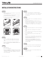
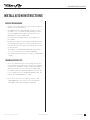
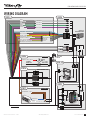
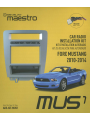
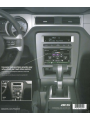
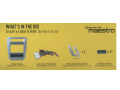
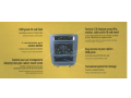
1
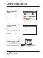
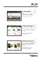
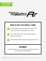
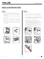
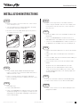
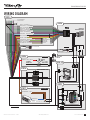
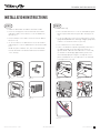
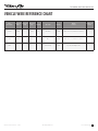
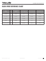
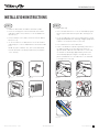
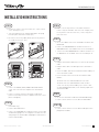
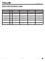
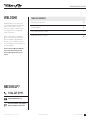
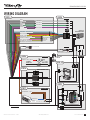
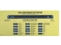
QUICK START GUIDE
THIS INSTALLATION REQUIRES AN IDATALINK
MAESTRO RR MODULE SOLD SEPARATELY.
QSG201309
6 STEPS TO GET STARTED
INSTALL THE WEBLINK
PLUG-IN
1
Go to:
idatalinkmaestro.com/plugin and
follow the installation steps.
Review the System Requirements
before installing.
REGISTER A WEBLINK
ACCOUNT
2
Go to:
idatalinkmaestro.com/register and
complete the registration process.
A confirmation email will be sent to you
requiring validation.
3
CONNECT YOUR MAESTRO RR
Use the included USB cable to connect
your Maestro RR module to your PC.
Maestro RR module required and sold separately.
NEED HELP?
877.212.6169
LOG INTO WEBLINK
Go to:
idatalinkmaestro.com/login.
Enter your username and
password, then click OK.
PROGRAM YOUR MODULE
4
5
Follow the installation steps
until your module is flashed and
download your install guide from
the Web.
Be sure to choose the MUS1 dash kit
accessory in STEP 4.
COMPLETE INSTALLATION
6
Follow the steps of the install
guide for Maestro RR with MUS1
Dash Kit and complete the
installation.
ADS recommends having this product
installed by a certified technician.
USER-CONFIGURABLE BUTTON BAR
CLIMATE
CONTROL SCREEN
15 BUTTONS TO CHOOSE FROM
REAR
DEFROST
HEATED SEATS
INCREASE FAN SPEED
COOLED SEATS
DECREASE FAN SPEED
AIR CONDITIONING
VEHICLE INFORMATION
SCREEN
FRONT DEFROST
GENERIC 1
MAX. AIR CONDITIONING
GENERIC 2
PERFORMANCE GAUGES
SCREEN
GENERIC 3
INCREASE TEMPERATURE
BLANK
DECREASE TEMPERATURE
1 YEAR LIMITED WARRANTY
Automotive Data Solutions Inc. (“ADS”) warrants to the original purchaser that this product shall be free of
defects in material and workmanship under normal use and circumstances, for the period of one (1) year
as of the original date of purchase.
In the event of any product malfunction during the Warranty period, the original purchaser must return
to the Authorized Dealer where it was originally purchased with the original proof of purchase. If a
malfunction is detected, the Authorized Dealer will elect to repair or replace the product at its discretion.
Labor costs may be applicable and are at the discretion of the Authorized Dealer.
ADS is not responsible for any damages whatsoever, including but not limited to any consequential
damages, incidental damages for loss of time, loss of earnings, commercial loss of economic opportunity
and the like that may or may not have resulted from the installation or operation of an iDatalink Maestro
product.
© Automotive Data Solutions Inc.
SELECT VEHICLE
PRINT PAGES NEEDED
HOW TO USE THIS INSTALL GUIDE
1
Open the Bookmarks menu and find your vehicle OR scroll
down until you find the install guide for your vehicle.
2
Print only the pages for your vehicle using the advanced
options in the Print menu.
3
Install your Maestro RR according to the guide for your vehicle.
WARNING
Pressing the printer icon or “quick printing” this document will print
all of the guides in this compilation.
NOTICE: Automotive Data Solutions Inc. (ADS) recommends having this installation performed by a certified technician. Logos and trademarks used here in
are the properties of their respective owners.
INSTALL GUIDE
Ford Mustang
Base 2010-2012
retains steering wheel controls Sync commands, sync BT and more!
PRODUCTS REQUIRED
OPTIONAL ACCESSORIES
PROGRAMMED FIRMWARE
iDatalink Maestro RR Radio Replacement Interface
iDatalink Maestro MUS1 Dash Kit
None

ADS-RR(SR)-FOR01-DS2
NOTICE: Automotive Data Solutions Inc. (ADS) recommends having this installation performed by a certified technician. Logos and trademarks used here
in are the properties of their respective owners.
Ford Mustang Base 2010-2012
WELCOME
TABLE OF CONTENTS
Congratulations on the purchase
of your iDatalink Maestro RR Radio
replacement solution. You are
now a few simple steps away from
enjoying your new car radio with
enhanced features.
Installation Instructions
3
Wiring Diagram
6
Vehicle Wire Reference Chart
7
Before starting your installation,
please ensure that your iDatalink
Maestro module is programmed
with the correct firmware for your
vehicle and that you carefully review
the install guide.
Radio Wire Reference Chart
8
Please note that Maestro RR will
only retain functionalities that
were originally available in the
vehicle.
NEED hELP?
1 866 427-2999
[email protected]
maestro.idatalink.com/support
www.12voltdata.com/forum
Automotive Data Solutions Inc. © 2014
ADS-RR(SR)-FOR01-DS2
maestro.idatalink.com
2
Ford Mustang Base 2010-2012
INSTALLATION INSTRUCTIONS
STEP 2
STEP 1
(with SYNC only)
• Unbox the MUS1 dash kit and the aftermarket radio.
• Insert the storage pocket into the backside of the MUS1
radio panel and secure it with the screws included in the
dash kit. (1.1)
• Unscrew and remove the 4 screws located underthe glove
box then open and remove the glove box carefully. (2.1 &
2.2)
• Choose 3 button covers and secure them onto the button
bar (1.2 & 1.3)
• Locate the SWI 2 wire in the vehicle SYNC harness: small
gauge BLUE/ORANGE wire. Warning: a bigger gauge blue/
red wire is located in the harness.) (2.3-2.5)
• Secure the MUS1 steel radio brackets to the aftermarket
radio using the screws included with the aftermarket radio.
(1.4)
NOTE: To replace a button cover, unscrew the button bar
from the backside of the dash kit and remove the button
cover carefully.
• Use a multimeter to test the SWI 2 wire.
• Connect the BLACK test probe to ground (-) and connect
the RED test probe to the wire SWI 2 wire. Have the
ignition and the radio ON. If the SWI 2 wire is connected,
the multimeter will display approximately 5 volts. This
value will drop upon pressing the steering wheel voice,
phone or OK button. Once the SWI 2 wire is located and
tested, go to the next step.
A/C
Fig. 1.1
Fig. 1.2
Fig. 2.1
Fig. 2.2
Fig. 1.3
Fig. 1.4
Fig. 2.3
Fig. 2.4
Fig. 2.5
4
Automotive Data Solutions Inc. © 2014
ADS-RR(SR)-FOR01-DS2
maestro.idatalink.com
3
Ford Mustang Base 2010-2012
INSTALLATION INSTRUCTIONS
STEP 6
STEP 3
• Connect the factory harness to the MUS1 T-harness.
Connect only the available connectors. For example, if the
factory harness has two connectors, connect only these
two connectors.
• Remove the shifter cover then remove the central console
cover carefully. (3.1, 3.2)
• Unscrew and remove the original radio panel. The plug
from this panel will not be reused. (3.3)
• Disconnect the factory radio and keep its factory harness
accessible for later use. (3.4)
STEP 7
• Access the OBDII connector located under the driver side
dashboard.
• Connect the RED/BROWN wire of MUS1 T-harness to
WHITE/BLUE wire of the OBDII connector located at pin 6.
• Connect the YELLOW/BROWN wire of MUS1 T-harness to
the WHITE wire of the OBDII connector located at pin 14.
Fig. 3.1
STEP 8
Fig. 3.2
• Plug the aftermarket radio harnesses into the aftermarket
radio.
• Plug the Data cable to the data port of the aftermarket
radio.
• Insert the Audio cable into the iDatalink 3.5 mm audio jack
of the aftermarket radio.
• Insert the RCA connectors into the aftermarket radio.
Fig. 3.3
NOTES:
Fig. 3.4
The RCA connectors labeled SUB IN are not used.
The RCA connectors labeled AUX IN can be used to
connect the factory 3.5 mm audio jack, in vehicles that
are NOT equipped with SYNC, to the auxiliary input of the
aftermarket radio.
STEP 4
• Cut the WHITE, GRAY, GREEN and PURPLE RCA tips.
Connect every wire to the aftermarket radio main harness
and match the wire colors.
STEP 9
• Connect every wire from the aftermarket radio main
harness to the MUS1 T-harness and match the wire colors.
(Refer to Diagram)
• Secure the aftermarket radio in the dashboardhousing.
• Connect all the harnesses to the Maestro RR module.
STEP 5
STEP 10
(with SYNC only)
• Connect all the harnesses to the MUS1 radio panel then
program the module.
• Cut the SWI 2 INPUT wire.
• Connect the PINK/RED wire of MUS1 T-harness to the SWI
2 INPUT wire going to the steering wheel. Insulate the wire
side going to the SYNC module and plug the SYNC harness
into the SYNC module.
4
Automotive Data Solutions Inc. © 2014
ADS-RR(SR)-FOR01-DS2
maestro.idatalink.com
4
Ford Mustang Base 2010-2012
INSTALLATION INSTRUCTIONS
MODULE PROGRAMMING
• Open the vehicle driver door, insert the key into the ignition
and turn it to the ACC position.
• The OEM Bluetooth is OFF by default. To activate it, go to
the radio screen, scroll down to FORD SETUP, press SET,
go to the OEM Bluetooth and press ON, then Press the
BACK button (circular shaped arrow).
• Scroll down, press FINISH and wait. Press START, then
press NEXT.
• Now follow the radio screen instructions while performing
the following steps: Turn the key to the OFF position, then
to the ACC position, turn it back to the OFF position, then to
the ACC position.
The module is now programmed and ready to be used. To
access the new menus, press on FORD FEATURES.
• Test all the functionalities then reassemble the dashboard
carefully.
TROUBLEShOOTING TIPS
• To reset the module back its factory settings, turn the key
to the OFF position then disconnect all connectors from the
module. Press and hold the module’s programming button
and connect all the connectors back to the module. Wait,
the module’s LED will fl ash RED rapidly (this may take up
to 10 seconds). Release the programming button. Wait, the
LED will turn solid GREEN for 2 seconds.
• For technical assistance call 1-866-427-2999 or e-mail
“[email protected]”. Visit us at “maestro.idatalink.
com/support” and “www.12voltdata.com/forum/”
1
Automotive Data Solutions Inc. © 2014
ADS-RR(SR)-FOR01-DS2
maestro.idatalink.com
5
Ford Mustang Base 2010-2012
WIRING DIAGRAM
STEP 4
CUT AND REMOVE
THE RCA JACKS
STEP 8
WHITE - LF SPEAKER (+)
WHITE/BLACK - LF SPEAKER (-)
GRAY - RF SPEAKER (+)
GRAY/BLACK - RF SPEAKER (-)
GREEN - LR SPEAKER (+)
GREEN/BLACK - LR SPEAKER (-)
PURPLE - RR SPEAKER (+)
PURPLE/BLACK - RR SPEAKER (-)
BLUE/WHITE - AMP. TURN ON (+)
BLACK - GROUND
RED - ACCESSORY (+)
YELLOW - 12V (+)
ORANGE - PARKING LIGHT (+)
PURPLE/WHITE - REVERSE LIGHT (+)
LTGREEN - E-BRAKE (-)
PINK - VEHICLE SPEED
YELLOW/BLACK - FOOT BRAKE
BROWN (NOT CONNECTED)
SUB IN
MAIN
HARNESS
CONNECT TO
AFTERMARKET RADIO
SEE RADIO
WIRE REFERENCE
CHART FOR
RADIO WIRE
COLORS
NOT CONNECTED
RCA CABLES
AUX IN
CONNECT AUX IN
ONLY IF YOU DON’T HAVE SYNC
STEP 5
SYNC HARNESS
INSULATE
WIRE
PINK/RED - SWI 2 (-) INPUT
STEERING
WHEEL SIDE
SYNC
MODULE SIDE
DATA AUDIO
USB CABLES CABLE CABLE
WIRES FROM
VEHICLE
STEP 10
Y
STEP 6
Z
X
FACTORY RADIO HARNESS
X
Y
Z
STEP 9
A
STEP 7
H
OBDII CONNECTOR
MAESTRO RR MODULE
YELLOW/BROWN - CAN2L
RED/BROWN - CAN2H
1
9
2
10
3
11
4
12
5
13
C
E
6
14
7
15
8
16
A
WHITE/BLUE
F
WHITE
C
D
H
G
F
E
D
LOOK FOR THE TWISTED WIRES
G
MUS1 T-HARNESS
4
Automotive Data Solutions Inc. © 2014
ADS-RR(SR)-FOR01-DS2
maestro.idatalink.com
6
Ford Mustang Base 2010-2012
VEHICLE WIRE REFERENCE CHART
Wire
Description
Connector
Name
Connector
Color
Connector
Type
Position
Wire Color
Polarity
Module
Location
Component
Locator
Can2H
OBDII
~
16 pin
06
White/Blue
(DATA)
OBDII connector, under driver side dash
~
Can2L
OBDII
~
16 pin
14
White
(DATA)
OBDII connector, under driver side dash
~
SWI 2
~
~
~
~
Blue/Orange
(MUX)
Sync unit, behind glove box
~
Automotive Data Solutions Inc. © 2014
ADS-RR(SR)-FOR01-DS2
maestro.idatalink.com
7
Ford Mustang Base 2010-2012
RADIO WIRE REFERENCE CHART
Wire
Description
Polarity
Wire Color on Maestro
T-Harness
Wire Color on Alpine cable
Wire Color on Kenwood cable
Wire Color on Pioneer cable
Parking Light
(+)
Orange
N/A
Orange/White
Orange/White
Reverse Light
(+)
Purple/White
Orange/White
Purple/White
Purple/White
E-Brake
(-)
Lt Green
Yellow/Blue
Lt Green
Lt Green
Foot Brake
(+)
Yellow/Black
Yellow/Black
N/A
N/A
VSS (vehicle speed sensor)
(DATA)
Pink
Green/White
N/A
Pink
Automotive Data Solutions Inc. © 2014
ADS-RR(SR)-FOR01-DS2
maestro.idatalink.com
8
INSTALL GUIDE
Ford Mustang
Shaker 500 & 1000 2010-2012
retains steering wheel controls Sync commands, sync BT and more!
PRODUCTS REQUIRED
OPTIONAL ACCESSORIES
PROGRAMMED FIRMWARE
iDatalink Maestro RR Radio Replacement Interface
iDatalink Maestro MUS1 Dash Kit
None

ADS-RR(SR)-FOR01-DS2
NOTICE: Automotive Data Solutions Inc. (ADS) recommends having this installation performed by a certified technician. Logos and trademarks used here
in are the properties of their respective owners.
Ford Mustang Shaker 500 & 1000 2010-2012
WELCOME
TABLE OF CONTENTS
Congratulations on the purchase
of your iDatalink Maestro RR Radio
replacement solution. You are
now a few simple steps away from
enjoying your new car radio with
enhanced features.
Installation Instructions
3
Wiring Diagram
6
Vehicle Wire Reference Chart
7
Before starting your installation,
please ensure that your iDatalink
Maestro module is programmed
with the correct firmware for your
vehicle and that you carefully review
the install guide.
Radio Wire Reference Chart
8
Please note that Maestro RR will
only retain functionalities that
were originally available in the
vehicle.
NEED hELP?
1 866 427-2999
[email protected]
maestro.idatalink.com/support
www.12voltdata.com/forum
Automotive Data Solutions Inc. © 2014
ADS-RR(SR)-FOR01-DS2
maestro.idatalink.com
2
Ford Mustang Shaker 500 & 1000 2010-2012
INSTALLATION INSTRUCTIONS
STEP 2
STEP 1
(with SYNC only)
• Unbox the MUS1 dash kit and the aftermarket radio.
• Insert the storage pocket into the backside of the MUS1
radio panel and secure it with the screws included in the
dash kit. (1.1)
• Unscrew and remove the 4 screws located underthe glove
box then open and remove the glove box carefully. (2.1 &
2.2)
• Choose 3 button covers and secure them onto the button
bar (1.2 & 1.3)
• Locate the SWI 2 wire in the vehicle SYNC harness: small
gauge BLUE/ORANGE wire. Warning: a bigger gauge blue/
red wire is located in the harness.) (2.3-2.5)
• Secure the MUS1 steel radio brackets to the aftermarket
radio using the screws included with the aftermarket radio.
(1.4)
NOTE: To replace a button cover, unscrew the button bar
from the backside of the dash kit and remove the button
cover carefully.
• Use a multimeter to test the SWI 2 wire.
• Connect the BLACK test probe to ground (-) and connect
the RED test probe to the wire SWI 2 wire. Have the
ignition and the radio ON. If the SWI 2 wire is connected,
the multimeter will display approximately 5 volts. This
value will drop upon pressing the steering wheel voice,
phone or OK button. Once the SWI 2 wire is located and
tested, go to the next step.
A/C
Fig. 1.1
Fig. 1.2
Fig. 2.1
Fig. 2.2
Fig. 1.3
Fig. 1.4
Fig. 2.3
Fig. 2.4
Fig. 2.5
1
Automotive Data Solutions Inc. © 2014
ADS-RR(SR)-FOR01-DS2
maestro.idatalink.com
3
Ford Mustang Shaker 500 & 1000 2010-2012
INSTALLATION INSTRUCTIONS
STEP 6
STEP 3
• Connect the factory harness to the MUS1 T-harness.
Connect only the available connectors. For example, if the
factory harness has two connectors, connect only these
two connectors.
• Remove the shifter cover then remove the central console
cover carefully. (3.1, 3.2)
• Unscrew and remove the original radio panel. The plug
from this panel will not be reused. (3.3)
• Disconnect the factory radio and keep its factory harness
accessible for later use. (3.4)
STEP 7
• Access the OBDII connector located under the driver side
dashboard.
• Connect the RED/BROWN wire of MUS1 T-harness to
WHITE/BLUE wire of the OBDII connector located at pin 6.
• Connect the YELLOW/BROWN wire of MUS1 T-harness to
the WHITE wire of the OBDII connector located at pin 14.
Fig. 3.1
STEP 8
Fig. 3.2
• Plug the aftermarket radio harnesses into the aftermarket
radio.
• Plug the Data cable to the data port of the aftermarket
radio.
• Insert the Audio cable into the iDatalink 3.5 mm audio jack
of the aftermarket radio.
• Insert the RCA connectors into the aftermarket radio.
Fig. 3.3
NOTES:
Fig. 3.4
The RCA connectors labeled SUB IN can be used to
feed the subwoofer channel of the factory amplifier.
The RCA connectors labeled AUX IN can be used to
connect the factory 3.5 mm audio jack, in vehicles that
are NOT equipped with SYNC, to the auxiliary input of the
aftermarket radio.
STEP 4
• Cut the WHITE, GRAY, GREEN and PURPLE RCA tips.
Connect every wire to the aftermarket radio main harness
and match the wire colors.
• Connect every wire from the aftermarket radio main
harness to the MUS1 T-harness and match the wire colors.
(Refer to Diagram)
STEP 9
• Secure the aftermarket radio in the dashboardhousing.
• Connect all the harnesses to the Maestro RR module.
STEP 5
STEP 10
(with SYNC only)
• Cut the SWI 2 INPUT wire.
• Connect all the harnesses to the MUS1 radio panel then
program the module.
• Connect the PINK/RED wire of MUS1 T-harness to the SWI
2 INPUT wire going to the steering wheel. Insulate the wire
side going to the SYNC module and plug the SYNC harness
into the SYNC module.
1
Automotive Data Solutions Inc. © 2014
ADS-RR(SR)-FOR01-DS2
maestro.idatalink.com
4
Ford Mustang Shaker 500 & 1000 2010-2012
INSTALLATION INSTRUCTIONS
MODULE PROGRAMMING
• Open the vehicle driver door, insert the key into the ignition
and turn it to the ACC position.
• The OEM Bluetooth is OFF by default. To activate it, go to
the radio screen, scroll down to FORD SETUP, press SET,
go to the OEM Bluetooth and press ON, then Press the
BACK button (circular shaped arrow).
• Scroll down, press FINISH and wait. Press START, then
press NEXT.
• Now follow the radio screen instructions while performing
the following steps: Turn the key to the OFF position, then
to the ACC position, turn it back to the OFF position, then to
the ACC position.
The module is now programmed and ready to be used. To
access the new menus, press on FORD FEATURES.
• Test all the functionalities then reassemble the dashboard
carefully.
TROUBLEShOOTING TIPS
• To reset the module back its factory settings, turn the key
to the OFF position then disconnect all connectors from the
module. Press and hold the module’s programming button
and connect all the connectors back to the module. Wait,
the module’s LED will fl ash RED rapidly (this may take up
to 10 seconds). Release the programming button. Wait, the
LED will turn solid GREEN for 2 seconds.
• For technical assistance call 1-866-427-2999 or e-mail
“[email protected]”. Visit us at “maestro.idatalink.
com/support” and “www.12voltdata.com/forum/”
1
Automotive Data Solutions Inc. © 2014
ADS-RR(SR)-FOR01-DS2
maestro.idatalink.com
5
Ford Mustang Shaker 500 & 1000 2010-2012
WIRING DIAGRAM
STEP 4
CUT AND REMOVE
THE RCA JACKS
STEP 8
WHITE - LF SPEAKER (+)
WHITE/BLACK - LF SPEAKER (-)
GRAY - RF SPEAKER (+)
GRAY/BLACK - RF SPEAKER (-)
GREEN - LR SPEAKER (+)
GREEN/BLACK - LR SPEAKER (-)
PURPLE - RR SPEAKER (+)
PURPLE/BLACK - RR SPEAKER (-)
BLUE/WHITE - AMP. TURN ON (+)
BLACK - GROUND
RED - ACCESSORY (+)
YELLOW - 12V (+)
ORANGE - PARKING LIGHT (+)
PURPLE/WHITE - REVERSE LIGHT (+)
LTGREEN - E-BRAKE (-)
PINK - VEHICLE SPEED
YELLOW/BLACK - FOOT BRAKE
BROWN (NOT CONNECTED)
MAIN
HARNESS
SEE RADIO
WIRE REFERENCE
CHART FOR
RADIO WIRE
COLORS
CONNECT TO
AFTERMARKET RADIO
RCA CABLES
SUB IN
AUX IN
CONNECT AUX IN
ONLY IF YOU DON’T HAVE SYNC
STEP 5
SYNC HARNESS
INSULATE
WIRE
PINK/RED - SWI 2 (-) INPUT
STEERING
WHEEL SIDE
SYNC
MODULE SIDE
DATA AUDIO
USB CABLES CABLE CABLE
WIRES FROM
VEHICLE
STEP 10
Y
STEP 6
Z
X
FACTORY RADIO HARNESS
X
Y
Z
STEP 9
A
STEP 7
H
OBDII CONNECTOR
MAESTRO RR MODULE
YELLOW/BROWN - CAN2L
RED/BROWN - CAN2H
1
9
2
10
3
11
4
12
5
13
C
E
6
14
7
15
8
16
A
WHITE/BLUE
F
WHITE
C
D
H
G
F
E
D
LOOK FOR THE TWISTED WIRES
G
MUS1 T-HARNESS
1
Automotive Data Solutions Inc. © 2014
ADS-RR(SR)-FOR01-DS2
maestro.idatalink.com
6
Ford Mustang Shaker 500 & 1000 2010-2012
VEHICLE WIRE REFERENCE CHART
Wire
Description
Connector
Name
Connector
Color
Connector
Type
Position
Wire Color
Polarity
Module
Location
Component
Locator
Can2H
OBDII
~
16 pin
06
White/Blue
(DATA)
OBDII connector, under driver side dash
~
Can2L
OBDII
~
16 pin
14
White
(DATA)
OBDII connector, under driver side dash
~
SWI 2
~
~
~
~
Blue/Orange
(MUX)
Sync unit, behind glove box
~
Automotive Data Solutions Inc. © 2014
ADS-RR(SR)-FOR01-DS2
maestro.idatalink.com
7
Ford Mustang Shaker 500 & 1000 2010-2012
RADIO WIRE REFERENCE CHART
Wire
Description
Polarity
Wire Color on Maestro
T-Harness
Wire Color on Alpine cable
Wire Color on Kenwood cable
Wire Color on Pioneer cable
Parking Light
(+)
Orange
N/A
Orange/White
Orange/White
Reverse Light
(+)
Purple/White
Orange/White
Purple/White
Purple/White
E-Brake
(-)
Lt Green
Yellow/Blue
Lt Green
Lt Green
Foot Brake
(+)
Yellow/Black
Yellow/Black
N/A
N/A
VSS (vehicle speed sensor)
(DATA)
Pink
Green/White
N/A
Pink
Automotive Data Solutions Inc. © 2014
ADS-RR(SR)-FOR01-DS2
maestro.idatalink.com
8
INSTALL GUIDE
Ford Mustang
Base 2013-2014
retains steering wheel controls Sync commands, sync BT and more!
PRODUCTS REQUIRED
OPTIONAL ACCESSORIES
PROGRAMMED FIRMWARE
iDatalink Maestro RR Radio Replacement Interface
iDatalink Maestro MUS1 Dash Kit
None

ADS-RR(SR)-FOR01-DS2
NOTICE: Automotive Data Solutions Inc. (ADS) recommends having this installation performed by a certified technician. Logos and trademarks used here
in are the properties of their respective owners.
Ford Mustang Base 2013-2014
WELCOME
TABLE OF CONTENTS
Congratulations on the purchase
of your iDatalink Maestro RR Radio
replacement solution. You are
now a few simple steps away from
enjoying your new car radio with
enhanced features.
Installation Instructions
3
Wiring Diagram
6
Vehicle Wire Reference Chart
7
Before starting your installation,
please ensure that your iDatalink
Maestro module is programmed
with the correct firmware for your
vehicle and that you carefully review
the install guide.
Radio Wire Reference Chart
8
Please note that Maestro RR will
only retain functionalities that
were originally available in the
vehicle.
NEED hELP?
1 866 427-2999
[email protected]
maestro.idatalink.com/support
www.12voltdata.com/forum
Automotive Data Solutions Inc. © 2014
ADS-RR(SR)-FOR01-DS2
maestro.idatalink.com
2
Ford Mustang Base 2013-2014
INSTALLATION INSTRUCTIONS
STEP 2
STEP 1
(with SYNC only)
• Unbox the MUS1 dash kit and the aftermarket radio.
• Insert the storage pocket into the backside of the MUS1
radio panel and secure it with the screws included in the
dash kit. (1.1)
• Unscrew and remove the 4 screws located underthe glove
box then open and remove the glove box carefully. (2.1 &
2.2)
• Choose 3 button covers and secure them onto the button
bar (1.2 & 1.3)
• Locate the SWI 2 wire in the vehicle SYNC harness: small
gauge BLUE/ORANGE wire. Warning: a bigger gauge blue/
red wire is located in the harness.) (2.3-2.5)
• Secure the MUS1 steel radio brackets to the aftermarket
radio using the screws included with the aftermarket radio.
(1.4)
NOTE: To replace a button cover, unscrew the button bar
from the backside of the dash kit and remove the button
cover carefully.
• Use a multimeter to test the SWI 2 wire.
• Connect the BLACK test probe to ground (-) and connect
the RED test probe to the wire SWI 2 wire. Have the
ignition and the radio ON. If the SWI 2 wire is connected,
the multimeter will display approximately 5 volts. This
value will drop upon pressing the steering wheel voice,
phone or OK button. Once the SWI 2 wire is located and
tested, go to the next step.
A/C
Fig. 1.1
Fig. 1.2
Fig. 2.1
Fig. 2.2
Fig. 1.3
Fig. 1.4
Fig. 2.3
Fig. 2.4
Fig. 2.5
5
Automotive Data Solutions Inc. © 2014
ADS-RR(SR)-FOR01-DS2
maestro.idatalink.com
3
Ford Mustang Base 2013-2014
INSTALLATION INSTRUCTIONS
STEP 6
STEP 3
• Connect the factory harness to the MUS1 T-harness.
Connect only the available connectors. For example, if the
factory harness has two connectors, connect only these
two connectors.
• Remove the shifter cover then remove the central console
cover carefully. (3.1, 3.2)
• Unscrew and remove the original radio panel. The plug
from this panel will not be reused. (3.3)
• Disconnect the factory radio and keep its factory harness
accessible for later use. (3.4)
STEP 7
• Access the OBDII connector located under the driver side
dashboard.
• Connect the RED/BROWN wire of MUS1 T-harness to
WHITE/BLUE wire of the OBDII connector located at pin 6.
• Connect the YELLOW/BROWN wire of MUS1 T-harness to
the WHITE wire of the OBDII connector located at pin 14.
Fig. 3.1
STEP 8
Fig. 3.2
• Plug the aftermarket radio harnesses into the aftermarket
radio.
• Plug the Data cable to the data port of the aftermarket
radio.
• Insert the Audio cable into the iDatalink 3.5 mm audio jack
of the aftermarket radio.
• Insert the RCA connectors into the aftermarket radio.
Fig. 3.3
NOTES:
Fig. 3.4
The RCA connectors labeled SUB IN are not used.
The RCA connectors labeled AUX IN can be used to
connect the factory 3.5 mm audio jack, in vehicles that
are NOT equipped with SYNC, to the auxiliary input of the
aftermarket radio.
STEP 4
• Connect the WHITE, GRAY, GREEN and PURPLE RCA
connectors to the low level outputs of the aftermarket
radio.
STEP 9
• Connect every wire from the aftermarket radio main
harness to the MUS1 T-harness and match the wire colors.
(Refer to Diagram)
• Secure the aftermarket radio in the dashboardhousing.
• Connect all the harnesses to the Maestro RR module.
STEP 5
STEP 10
(with SYNC only)
• Connect all the harnesses to the MUS1 radio panel then
program the module.
• Cut the SWI 2 INPUT wire.
• Connect the PINK/RED wire of MUS1 T-harness to the SWI
2 INPUT wire going to the steering wheel. Insulate the wire
side going to the SYNC module and plug the SYNC harness
into the SYNC module.
5
Automotive Data Solutions Inc. © 2014
ADS-RR(SR)-FOR01-DS2
maestro.idatalink.com
4
Ford Mustang Base 2013-2014
INSTALLATION INSTRUCTIONS
MODULE PROGRAMMING
• Open the vehicle driver door, insert the key into the ignition
and turn it to the ACC position.
• The OEM Bluetooth is OFF by default. To activate it, go to
the radio screen, scroll down to FORD SETUP, press SET,
go to the OEM Bluetooth and press ON, then Press the
BACK button (circular shaped arrow).
• Scroll down, press FINISH and wait. Press START, then
press NEXT.
• Now follow the radio screen instructions while performing
the following steps: Turn the key to the OFF position, then
to the ACC position, turn it back to the OFF position, then to
the ACC position.
The module is now programmed and ready to be used. To
access the new menus, press on FORD FEATURES.
• Test all the functionalities then reassemble the dashboard
carefully.
TROUBLEShOOTING TIPS
• To reset the module back its factory settings, turn the key
to the OFF position then disconnect all connectors from the
module. Press and hold the module’s programming button
and connect all the connectors back to the module. Wait,
the module’s LED will fl ash RED rapidly (this may take up
to 10 seconds). Release the programming button. Wait, the
LED will turn solid GREEN for 2 seconds.
• For technical assistance call 1-866-427-2999 or e-mail
“[email protected]”. Visit us at “maestro.idatalink.
com/support” and “www.12voltdata.com/forum/”
1
Automotive Data Solutions Inc. © 2014
ADS-RR(SR)-FOR01-DS2
maestro.idatalink.com
5
Ford Mustang Base 2013-2014
WIRING DIAGRAM
STEP 4
CUT AND REMOVE
THE RCA JACKS
STEP 8
WHITE - LF SPEAKER (+)
WHITE/BLACK - LF SPEAKER (-)
GRAY - RF SPEAKER (+)
GRAY/BLACK - RF SPEAKER (-)
GREEN - LR SPEAKER (+)
GREEN/BLACK - LR SPEAKER (-)
PURPLE - RR SPEAKER (+)
PURPLE/BLACK - RR SPEAKER (-)
BLUE/WHITE - AMP. TURN ON (+)
BLACK - GROUND
RED - ACCESSORY (+)
YELLOW - 12V (+)
ORANGE - PARKING LIGHT (+)
PURPLE/WHITE - REVERSE LIGHT (+)
LTGREEN - E-BRAKE (-)
PINK - VEHICLE SPEED
YELLOW/BLACK - FOOT BRAKE
BROWN (NOT CONNECTED)
SUB IN
MAIN
HARNESS
CONNECT TO
AFTERMARKET RADIO
SEE RADIO
WIRE REFERENCE
CHART FOR
RADIO WIRE
COLORS
NOT CONNECTED
RCA CABLES
AUX IN
CONNECT AUX IN
ONLY IF YOU DON’T HAVE SYNC
STEP 5
SYNC HARNESS
INSULATE
WIRE
PINK/RED - SWI 2 (-) INPUT
STEERING
WHEEL SIDE
SYNC
MODULE SIDE
DATA AUDIO
USB CABLES CABLE CABLE
WIRES FROM
VEHICLE
STEP 10
Y
STEP 6
Z
X
FACTORY RADIO HARNESS
X
Y
Z
STEP 9
A
STEP 7
H
OBDII CONNECTOR
MAESTRO RR MODULE
YELLOW/BROWN - CAN2L
RED/BROWN - CAN2H
1
9
2
10
3
11
4
12
5
13
C
E
6
14
7
15
8
16
A
WHITE/BLUE
F
WHITE
C
D
H
G
F
E
D
LOOK FOR THE TWISTED WIRES
G
MUS1 T-HARNESS
5
Automotive Data Solutions Inc. © 2014
ADS-RR(SR)-FOR01-DS2
maestro.idatalink.com
6
Ford Mustang Base 2013-2014
VEHICLE WIRE REFERENCE CHART
Wire
Description
Connector
Name
Connector
Color
Connector
Type
Position
Wire Color
Polarity
Module
Location
Component
Locator
Can2H
OBDII
~
16 pin
06
White/Blue
(DATA)
OBDII connector, under driver side dash
~
Can2L
OBDII
~
16 pin
14
White
(DATA)
OBDII connector, under driver side dash
~
SWI 2
~
~
~
~
Blue
(MUX)
SYNC unit, behind glove box
~
Automotive Data Solutions Inc. © 2014
ADS-RR(SR)-FOR01-DS2
maestro.idatalink.com
7
Ford Mustang Base 2013-2014
RADIO WIRE REFERENCE CHART
Wire
Description
Polarity
Wire Color on Maestro
T-Harness
Wire Color on Alpine cable
Wire Color on Kenwood cable
Wire Color on Pioneer cable
Parking Light
(+)
Orange
N/A
Orange/White
Orange/White
Reverse Light
(+)
Purple/White
Orange/White
Purple/White
Purple/White
E-Brake
(-)
Lt Green
Yellow/Blue
Lt Green
Lt Green
Foot Brake
(+)
Yellow/Black
Yellow/Black
N/A
N/A
VSS (vehicle speed sensor)
(DATA)
Pink
Green/White
N/A
Pink
Automotive Data Solutions Inc. © 2014
ADS-RR(SR)-FOR01-DS2
maestro.idatalink.com
8
INSTALL GUIDE
Ford Mustang
Shaker 2013-2014
retains steering wheel controls Sync commands, sync BT and more!
PRODUCTS REQUIRED
OPTIONAL ACCESSORIES
PROGRAMMED FIRMWARE
iDatalink Maestro RR Radio Replacement Interface
iDatalink Maestro MUS1 Dash Kit
None

ADS-RR(SR)-FOR01-DS2
NOTICE: Automotive Data Solutions Inc. (ADS) recommends having this installation performed by a certified technician. Logos and trademarks used here
in are the properties of their respective owners.
Ford Mustang Shaker 2013-2014
WELCOME
TABLE OF CONTENTS
Congratulations on the purchase
of your iDatalink Maestro RR Radio
replacement solution. You are
now a few simple steps away from
enjoying your new car radio with
enhanced features.
Installation Instructions
3
Wiring Diagram
6
Vehicle Wire Reference Chart
7
Before starting your installation,
please ensure that your iDatalink
Maestro module is programmed
with the correct firmware for your
vehicle and that you carefully review
the install guide.
Radio Wire Reference Chart
8
Please note that Maestro RR will
only retain functionalities that
were originally available in the
vehicle.
NEED hELP?
1 866 427-2999
[email protected]
maestro.idatalink.com/support
www.12voltdata.com/forum
Automotive Data Solutions Inc. © 2014
ADS-RR(SR)-FOR01-DS2
maestro.idatalink.com
2
Ford Mustang Shaker 2013-2014
INSTALLATION INSTRUCTIONS
STEP 2
STEP 1
(with SYNC only)
• Unbox the MUS1 dash kit and the aftermarket radio.
• Insert the storage pocket into the backside of the MUS1
radio panel and secure it with the screws included in the
dash kit. (1.1)
• Unscrew and remove the 4 screws located underthe glove
box then open and remove the glove box carefully. (2.1 &
2.2)
• Choose 3 button covers and secure them onto the button
bar (1.2 & 1.3)
• Locate the SWI 2 wire in the vehicle SYNC harness: small
gauge BLUE/ORANGE wire. Warning: a bigger gauge blue/
red wire is located in the harness.) (2.3-2.5)
• Secure the MUS1 steel radio brackets to the aftermarket
radio using the screws included with the aftermarket radio.
(1.4)
NOTE: To replace a button cover, unscrew the button bar
from the backside of the dash kit and remove the button
cover carefully.
• Use a multimeter to test the SWI 2 wire.
• Connect the BLACK test probe to ground (-) and connect
the RED test probe to the wire SWI 2 wire. Have the
ignition and the radio ON. If the SWI 2 wire is connected,
the multimeter will display approximately 5 volts. This
value will drop upon pressing the steering wheel voice,
phone or OK button. Once the SWI 2 wire is located and
tested, go to the next step.
A/C
Fig. 1.1
Fig. 1.2
Fig. 2.1
Fig. 2.2
Fig. 1.3
Fig. 1.4
Fig. 2.3
Fig. 2.4
Fig. 2.5
2
Automotive Data Solutions Inc. © 2014
ADS-RR(SR)-FOR01-DS2
maestro.idatalink.com
3
Ford Mustang Shaker 2013-2014
INSTALLATION INSTRUCTIONS
STEP 6
STEP 3
• Connect the factory harness to the MUS1 T-harness.
Connect only the available connectors. For example, if the
factory harness has two connectors, connect only these
two connectors.
• Remove the shifter cover then remove the central console
cover carefully. (3.1, 3.2)
• Unscrew and remove the original radio panel. The plug
from this panel will not be reused. (3.3)
• Disconnect the factory radio and keep its factory harness
accessible for later use. (3.4)
STEP 7
• Access the OBDII connector located under the driver side
dashboard.
• Connect the RED/BROWN wire of MUS1 T-harness to
WHITE/BLUE wire of the OBDII connector located at pin 6.
• Connect the YELLOW/BROWN wire of MUS1 T-harness to
the WHITE wire of the OBDII connector located at pin 14.
Fig. 3.1
STEP 8
Fig. 3.2
• Plug the aftermarket radio harnesses into the aftermarket
radio.
• Plug the Data cable to the data port of the aftermarket
radio.
• Insert the Audio cable into the iDatalink 3.5 mm audio jack
of the aftermarket radio.
• Insert the RCA connectors into the aftermarket radio.
Fig. 3.3
NOTES:
Fig. 3.4
The RCA connectors labeled SUB IN are not used
The RCA connectors labeled AUX IN can be used to
connect the factory 3.5 mm audio jack, in vehicles that
are NOT equipped with SYNC, to the auxiliary input of the
aftermarket radio.
STEP 4
• Connect the WHITE, GRAY, GREEN and PURPLE RCA
connectors to the low level outputs of the aftermarket
radio.
STEP 9
• Connect every wire from the aftermarket radio main
harness to the MUS1 T-harness and match the wire colors.
(Refer to Diagram)
• Secure the aftermarket radio in the dashboardhousing.
• Connect all the harnesses to the Maestro RR module.
STEP 5
STEP 10
(with SYNC only)
• Connect all the harnesses to the MUS1 radio panel then
program the module.
• Cut the SWI 2 INPUT wire.
• Connect the PINK/RED wire of MUS1 T-harness to the SWI
2 INPUT wire going to the steering wheel. Insulate the wire
side going to the SYNC module and plug the SYNC harness
into the SYNC module.
2
Automotive Data Solutions Inc. © 2014
ADS-RR(SR)-FOR01-DS2
maestro.idatalink.com
4
Ford Mustang Shaker 2013-2014
INSTALLATION INSTRUCTIONS
MODULE PROGRAMMING
• Open the vehicle driver door, insert the key into the ignition
and turn it to the ACC position.
• The OEM Bluetooth is OFF by default. To activate it, go to
the radio screen, scroll down to FORD SETUP, press SET,
go to the OEM Bluetooth and press ON, then Press the
BACK button (circular shaped arrow).
• Scroll down, press FINISH and wait. Press START, then
press NEXT.
• Now follow the radio screen instructions while performing
the following steps: Turn the key to the OFF position, then
to the ACC position, turn it back to the OFF position, then to
the ACC position.
The module is now programmed and ready to be used. To
access the new menus, press on FORD FEATURES.
• Test all the functionalities then reassemble the dashboard
carefully.
TROUBLEShOOTING TIPS
• To reset the module back its factory settings, turn the key
to the OFF position then disconnect all connectors from the
module. Press and hold the module’s programming button
and connect all the connectors back to the module. Wait,
the module’s LED will fl ash RED rapidly (this may take up
to 10 seconds). Release the programming button. Wait, the
LED will turn solid GREEN for 2 seconds.
• For technical assistance call 1-866-427-2999 or e-mail
“[email protected]”. Visit us at “maestro.idatalink.
com/support” and “www.12voltdata.com/forum/”
1
Automotive Data Solutions Inc. © 2014
ADS-RR(SR)-FOR01-DS2
maestro.idatalink.com
5
Ford Mustang Shaker 2013-2014
WIRING DIAGRAM
STEP 8
STEP 4
RCA CABLES
WHITE
WHITE/BLACK
GRAY
GRAY/BLACK
GREEN
GREEN/BLACK
PURPLE
PURPLE/BLACK
LF RCA INPUT
RF RCA INPUT
LR RCA INPUT
RR RCA INPUT
MAIN
HARNESS
BLUE/WHITE - AMP. TURN ON (+)
BLACK - GROUND
RED - ACCESSORY (+)
YELLOW - 12V (+)
ORANGE - PARKING LIGHT (+)
PURPLE/WHITE - REVERSE LIGHT (+)
LTGREEN - E-BRAKE (-)
PINK - VEHICLE SPEED
YELLOW/BLACK - FOOT BRAKE
BROWN (NOT CONNECTED)
SUB IN
CONNECT TO
AFTERMARKET RADIO
SEE RADIO
WIRE REFERENCE
CHART FOR
RADIO WIRE
COLORS
NOT CONNECTED
RCA CABLES
AUX IN
CONNECT AUX IN
ONLY IF YOU DON’T HAVE SYNC
STEP 5
SYNC HARNESS
INSULATE
WIRE
PINK/RED - SWI 2 (-) INPUT
STEERING
WHEEL SIDE
SYNC
MODULE SIDE
DATA AUDIO
USB CABLES CABLE CABLE
WIRES FROM
VEHICLE
STEP 10
Y
STEP 6
Z
X
FACTORY RADIO HARNESS
X
Y
Z
STEP 9
A
STEP 7
H
OBDII CONNECTOR
MAESTRO RR MODULE
YELLOW/BROWN - CAN2L
RED/BROWN - CAN2H
1
9
2
10
3
11
4
12
5
13
C
E
6
14
7
15
8
16
A
WHITE/BLUE
F
WHITE
C
D
H
G
F
E
D
LOOK FOR THE TWISTED WIRES
G
MUS1 T-HARNESS
2
Automotive Data Solutions Inc. © 2014
ADS-RR(SR)-FOR01-DS2
maestro.idatalink.com
6
Ford Mustang Shaker 2013-2014
VEHICLE WIRE REFERENCE CHART
Wire
Description
Connector
Name
Connector
Color
Connector
Type
Position
Wire Color
Polarity
Module
Location
Component
Locator
Can2H
OBDII
~
16 pin
06
White/Blue
(DATA)
OBDII connector, under driver side dash
~
Can2L
OBDII
~
16 pin
14
White
(DATA)
OBDII connector, under driver side dash
~
SWI 2
~
~
~
~
Blue
(MUX)
SYNC unit, behind glove box
~
Automotive Data Solutions Inc. © 2014
ADS-RR(SR)-FOR01-DS2
maestro.idatalink.com
7
Ford Mustang Shaker 2013-2014
RADIO WIRE REFERENCE CHART
Wire
Description
Polarity
Wire Color on Maestro
T-Harness
Wire Color on Alpine cable
Wire Color on Kenwood cable
Wire Color on Pioneer cable
Parking Light
(+)
Orange
N/A
Orange/White
Orange/White
Reverse Light
(+)
Purple/White
Orange/White
Purple/White
Purple/White
E-Brake
(-)
Lt Green
Yellow/Blue
Lt Green
Lt Green
Foot Brake
(+)
Yellow/Black
Yellow/Black
N/A
N/A
VSS (vehicle speed sensor)
(DATA)
Pink
Green/White
N/A
Pink
Automotive Data Solutions Inc. © 2014
ADS-RR(SR)-FOR01-DS2
maestro.idatalink.com
8
INSTALL GUIDE
Ford Mustang
Shaker Pro 2013-2014
retains steering wheel controls Sync commands, sync BT and more!
PRODUCTS REQUIRED
OPTIONAL ACCESSORIES
PROGRAMMED FIRMWARE
iDatalink Maestro RR Radio Replacement Interface
iDatalink Maestro MUS1 Dash Kit
None

ADS-RR(SR)-FOR01-DS2
NOTICE: Automotive Data Solutions Inc. (ADS) recommends having this installation performed by a certified technician. Logos and trademarks used here
in are the properties of their respective owners.
Ford Mustang Shaker Pro 2013-2014
WELCOME
TABLE OF CONTENTS
Congratulations on the purchase
of your iDatalink Maestro RR Radio
replacement solution. You are
now a few simple steps away from
enjoying your new car radio with
enhanced features.
Installation Instructions
3
Wiring Diagram
6
Vehicle Wire Reference Chart
7
Before starting your installation,
please ensure that your iDatalink
Maestro module is programmed
with the correct firmware for your
vehicle and that you carefully review
the install guide.
Radio Wire Reference Chart
8
Please note that Maestro RR will
only retain functionalities that
were originally available in the
vehicle.
NEED hELP?
1 866 427-2999
[email protected]
maestro.idatalink.com/support
www.12voltdata.com/forum
Automotive Data Solutions Inc. © 2014
ADS-RR(SR)-FOR01-DS2
maestro.idatalink.com
2
Ford Mustang Shaker Pro 2013-2014
INSTALLATION INSTRUCTIONS
STEP 2
STEP 1
(with SYNC only)
• Unbox the MUS1 dash kit and the aftermarket radio.
• Insert the storage pocket into the backside of the MUS1
radio panel and secure it with the screws included in the
dash kit. (1.1)
• Unscrew and remove the 4 screws located underthe glove
box then open and remove the glove box carefully. (2.1 &
2.2)
• Choose 3 button covers and secure them onto the button
bar (1.2 & 1.3)
• Locate the SWI 2 wire in the vehicle SYNC harness: small
gauge BLUE/ORANGE wire. Warning: a bigger gauge blue/
red wire is located in the harness.) (2.3-2.5)
• Secure the MUS1 steel radio brackets to the aftermarket
radio using the screws included with the aftermarket radio.
(1.4)
NOTE: To replace a button cover, unscrew the button bar
from the backside of the dash kit and remove the button
cover carefully.
• Use a multimeter to test the SWI 2 wire.
• Connect the BLACK test probe to ground (-) and connect
the RED test probe to the wire SWI 2 wire. Have the
ignition and the radio ON. If the SWI 2 wire is connected,
the multimeter will display approximately 5 volts. This
value will drop upon pressing the steering wheel voice,
phone or OK button. Once the SWI 2 wire is located and
tested, go to the next step.
A/C
Fig. 1.1
Fig. 1.2
Fig. 2.1
Fig. 2.2
Fig. 1.3
Fig. 1.4
Fig. 2.3
Fig. 2.4
Fig. 2.5
3
Automotive Data Solutions Inc. © 2014
ADS-RR(SR)-FOR01-DS2
maestro.idatalink.com
3
Ford Mustang Shaker Pro 2013-2014
INSTALLATION INSTRUCTIONS
STEP 6
STEP 3
• Connect the factory harness to the MUS1 T-harness.
Connect only the available connectors. For example, if the
factory harness has two connectors, connect only these
two connectors.
• Remove the shifter cover then remove the central console
cover carefully. (3.1, 3.2)
• Unscrew and remove the original radio panel. The plug
from this panel will not be reused. (3.3)
• Disconnect the factory radio and keep its factory harness
accessible for later use. (3.4)
STEP 7
• Access the OBDII connector located under the driver side
dashboard.
• Connect the RED/BROWN wire of MUS1 T-harness to
WHITE/BLUE wire of the OBDII connector located at pin 6.
• Connect the YELLOW/BROWN wire of MUS1 T-harness to
the WHITE wire of the OBDII connector located at pin 14.
Fig. 3.1
STEP 8
Fig. 3.2
• Plug the aftermarket radio harnesses into the aftermarket
radio.
• Plug the Data cable to the data port of the aftermarket
radio.
• Insert the Audio cable into the iDatalink 3.5 mm audio jack
of the aftermarket radio.
• Insert the RCA connectors into the aftermarket radio.
Fig. 3.3
NOTES:
Fig. 3.4
The RCA connectors labeled SUB IN can be used to feed
the factory amplifier and trunk mounted subwoofers that
are part of the Shaker Pro system.
STEP 4
The RCA connectors labeled AUX IN can be used to
connect the factory 3.5 mm audio jack, in vehicles that
are NOT equipped with SYNC, to the auxiliary input of the
aftermarket radio.
• Connect the WHITE, GRAY, GREEN and PURPLE RCA
connectors to the low level outputs of the aftermarket
radio.
• Connect every wire from the aftermarket radio main
harness to the MUS1 T-harness and match the wire colors.
(Refer to Diagram)
STEP 9
• Secure the aftermarket radio in the dashboardhousing.
STEP 5
• Connect all the harnesses to the Maestro RR module.
(with SYNC only)
STEP 10
• Cut the SWI 2 INPUT wire.
• Connect the PINK/RED wire of MUS1 T-harness to the SWI
2 INPUT wire going to the steering wheel. Insulate the wire
side going to the SYNC module and plug the SYNC harness
into the SYNC module.
• Connect all the harnesses to the MUS1 radio panel then
program the module.
3
Automotive Data Solutions Inc. © 2014
ADS-RR(SR)-FOR01-DS2
maestro.idatalink.com
4
Ford Mustang Shaker Pro 2013-2014
INSTALLATION INSTRUCTIONS
MODULE PROGRAMMING
• Open the vehicle driver door, insert the key into the ignition
and turn it to the ACC position.
• The OEM Bluetooth is OFF by default. To activate it, go to
the radio screen, scroll down to FORD SETUP, press SET,
go to the OEM Bluetooth and press ON, then Press the
BACK button (circular shaped arrow).
• Scroll down, press FINISH and wait. Press START, then
press NEXT.
• Now follow the radio screen instructions while performing
the following steps: Turn the key to the OFF position, then
to the ACC position, turn it back to the OFF position, then to
the ACC position.
The module is now programmed and ready to be used. To
access the new menus, press on FORD FEATURES.
• Test all the functionalities then reassemble the dashboard
carefully.
TROUBLEShOOTING TIPS
• To reset the module back its factory settings, turn the key
to the OFF position then disconnect all connectors from the
module. Press and hold the module’s programming button
and connect all the connectors back to the module. Wait,
the module’s LED will fl ash RED rapidly (this may take up
to 10 seconds). Release the programming button. Wait, the
LED will turn solid GREEN for 2 seconds.
• For technical assistance call 1-866-427-2999 or e-mail
“[email protected]”. Visit us at “maestro.idatalink.
com/support” and “www.12voltdata.com/forum/”
1
Automotive Data Solutions Inc. © 2014
ADS-RR(SR)-FOR01-DS2
maestro.idatalink.com
5
Ford Mustang Shaker Pro 2013-2014
WIRING DIAGRAM
STEP 8
STEP 4
RCA CABLES
WHITE
WHITE/BLACK
GRAY
GRAY/BLACK
GREEN
GREEN/BLACK
PURPLE
PURPLE/BLACK
LF RCA INPUT
RF RCA INPUT
LR RCA INPUT
RR RCA INPUT
MAIN
HARNESS
BLUE/WHITE - AMP. TURN ON (+)
BLACK - GROUND
RED - ACCESSORY (+)
YELLOW - 12V (+)
ORANGE - PARKING LIGHT (+)
PURPLE/WHITE - REVERSE LIGHT (+)
LTGREEN - E-BRAKE (-)
PINK - VEHICLE SPEED
YELLOW/BLACK - FOOT BRAKE
BROWN (NOT CONNECTED)
CONNECT TO
AFTERMARKET RADIO
SEE RADIO
WIRE REFERENCE
CHART FOR
RADIO WIRE
COLORS
RCA CABLES
SUB IN
AUX IN
CONNECT AUX IN
ONLY IF YOU DON’T HAVE SYNC
STEP 5
SYNC HARNESS
INSULATE
WIRE
PINK/RED - SWI 2 (-) INPUT
STEERING
WHEEL SIDE
SYNC
MODULE SIDE
DATA AUDIO
USB CABLES CABLE CABLE
WIRES FROM
VEHICLE
STEP 10
Y
STEP 6
Z
X
FACTORY RADIO HARNESS
X
Y
Z
STEP 9
A
STEP 7
H
OBDII CONNECTOR
MAESTRO RR MODULE
YELLOW/BROWN - CAN2L
RED/BROWN - CAN2H
1
9
2
10
3
11
4
12
5
13
C
E
6
14
7
15
8
16
A
WHITE/BLUE
F
WHITE
C
D
H
G
F
E
D
LOOK FOR THE TWISTED WIRES
G
MUS1 T-HARNESS
3
Automotive Data Solutions Inc. © 2014
ADS-RR(SR)-FOR01-DS2
maestro.idatalink.com
6
Ford Mustang Shaker Pro 2013-2014
VEHICLE WIRE REFERENCE CHART
Wire
Description
Connector
Name
Connector
Color
Connector
Type
Position
Wire Color
Polarity
Module
Location
Component
Locator
Can2H
OBDII
~
16 pin
06
White/Blue
(DATA)
OBDII connector, under driver side dash
~
Can2L
OBDII
~
16 pin
14
White
(DATA)
OBDII connector, under driver side dash
~
SWI 2
~
~
~
~
Blue
(MUX)
SYNC unit, behind glove box
~
Automotive Data Solutions Inc. © 2014
ADS-RR(SR)-FOR01-DS2
maestro.idatalink.com
7
Ford Mustang Shaker Pro 2013-2014
RADIO WIRE REFERENCE CHART
Wire
Description
Polarity
Wire Color on Maestro
T-Harness
Wire Color on Alpine cable
Wire Color on Kenwood cable
Wire Color on Pioneer cable
Parking Light
(+)
Orange
N/A
Orange/White
Orange/White
Reverse Light
(+)
Purple/White
Orange/White
Purple/White
Purple/White
E-Brake
(-)
Lt Green
Yellow/Blue
Lt Green
Lt Green
Foot Brake
(+)
Yellow/Black
Yellow/Black
N/A
N/A
VSS (vehicle speed sensor)
(DATA)
Pink
Green/White
N/A
Pink
Automotive Data Solutions Inc. © 2014
ADS-RR(SR)-FOR01-DS2
maestro.idatalink.com
8
(Gmaestro
CAR RADIO
INSTALLATION KIT
KIT D'INSTAllATION AUTORADIO
KIT DE INSTALACION PARA AUTORRAD/0
FORD MUSTANG
2010-2014
Part #I No. Piece IN~ Pieza
ADS-KIT-MUS1
WHAT'S IN THE BOX
Ce qu'il ya dans la boite - Oue hay en Ia caja
~aestro
x2
x17
RADIO PANEL
PLUG &PLAY HARNESS
STEEL RADIO BRACKETS
BUTTON COVERS
Panneau de radio - Panel frontal del radio
Hamais d'installation - Ames de cableado
Supports de radio en acier - Soportes de acero para el radio
Couvercles de boutons - Cubre-botones
Factory LCD displays song title,
station, radio caller ID and more!
OEM grade fit and finish
Assemblage de qualite et finition d'origine
Calidad de montaje y acabado originates
l'ecran d'origine affiche le titre de la chanson,la station
de radio. l'identification de rappelant et ptusl
La pantalla original identifica canciones. estaciones de radio.
llamadas entrantes ;y mucho mas!
3customizable quick
access buttons
3boutons d'acces rapide personnalisables
3botones de acceso rapido personalizables
Control your car's temperature
directly from your radio's touch screen
Controlez la temperature de votre voiture
directement apartir de recran tactile de votre radio
Controle la temperatura de su auto directamente
desde Ia pantalla tactil de su radio
---~.....
Easy access to your radio's
USB ports
Acces facile aux ports USB de votre radio
Facil acceso alos puertos USB de su radio
Convenient pocket for storage
Pochette de rangement pratique
Practico compartimento para otros usos
BAR
BUTTON
RABLE
USER-CONFIGU
configurable
botones
de
Barra
Barre de boutons configurable
•
•
•
CLIMATE
R
QUJ
15 BUTTONS TO CHOOSE FROM
CLIMATE CONTROL SCREEN
lcran de controle de ctimat
REAR DEFROST
Degivreur arri~re
Choisissez parmi 15 boutons - Elija entre 15 botones
Paatalla del cii!TidtlladDf
HEATED SEATS
Sieges chauffants
PERFORMAMCE 6AIIGES SCREEN
tcran de cadrans de performance
Oesempaniid!N poslefiiN
VEHICLE INFORMATION SCREEN
lcran d"information du velllcule
Astentos CJieladables
Pan/ilia de 1t1a1 rlt)fts de rendlmtento
hntalla de infonnaC!On del vehiCtllc
COOLED SEATS
INCREASE TEMPERATURE
GENERIC 1
Aslentos retogerados
AJJmentar temperatura
Gendtico 1
Sieges climatlses
Augmenter temperature
Generique 1
AIR CONDITIONING
DECREASE TEMPERATURE
Air cUmatlse
Aile iiClllldlcionado
Baisser temp~rature
Reduc11 temperatura
GENERIC 2
Generique 2
Gentf/CO l
FRONT DEFROST
Degivreur mnt
lJestmpairidor IIMteiD
INCREASE FAit SPEED
Augmenter ventilation
GENERIC 3
MAX. AIR CONDITJOIIIIIG
AAr dimatise max.
Alre acondraonado max
Aumen/3r tentrla()()ll
DECREASE WI SPEED
RHuire ventilation
Rtriuclf venl1iaaon
•
••
Generique 3
fierttflto 3
BUNK
Vide
~0


![INSTALL GUIDE OEM-IDS(RS)-BM1-[ADS-BM1]-EN](http://vs1.manualzilla.com/store/data/005803017_1-bfa667bd4ebc7540cfa057e535ebd2e9-150x150.png)