1
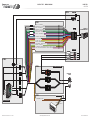
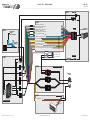
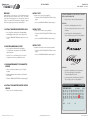
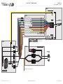
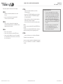
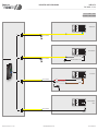
• 20130729
INSTALL GUIDE
WITH GM5 T-HARNESS
RETAINS STEERING WHEEL CONTROLS,
ONSTARTM, ONSTARTM BLUETOOTH,
XMTM SATELLITE AND MORE!
PRODUCTS REQUIRED
iDatalink Maestro RR Radio Replacement Interface
iDatalink Maestro GM5 Installation Harness
OPTIONAL ACCESSORIES
None
PROGRAMMED FIRMWARE
ADS-RR(SR)-GMS05-DS-EN
NOTICE: Automotive Data Solutions Inc. (ADS) accepts no responsability for
any electrical damage resulting from improper installation of this product,
be that either damage to the vehicle itself or to the installed device. ADS
recommends having this installation performed by a certified technician.
Please review this guide carefully before beginning any work. Logos and
trademarks used herein are the properties of their respective owners.
Automotive Data Solutions Inc. © 2013
maestro.idatalink.com
PAGE 2 OF 9
• 20130729
GETTING STARTED
WELCOME
Congratulations on the purchase of your iDatalink Maestro
RR Radio replacement solution. You are now s few simple
steps away from enjoying your new car radio with enhanced
features. To complete the installation of your product, please
follow the step-by-step instructions outlined below.
1- INSTALL THE WEBLINK UPDATER PLUG-IN
• Go to "http://maestro.idatalink.com/support#tab=_
weblink-plugin" and read the system requirements
• Click the DOWNLOAD NOW button and run the setup.exe
file
INSTALL TYPE 1
Used for vehicles with a factory amplifier*
• Follow the INSTALLATION INSTRUCTIONS listed on page 4.
• Refer to the WIRING DIAGRAM included on page 5.
INSTALL TYPE 2
Used for vehicles without a factory amplifier*
• Follow the INSTALLATION INSTRUCTIONS listed on page 6.
• Refer to the WIRING DIAGRAM included on page 7.
*HOW TO DETERMINE IF YOUR VEHICLE IS EQUIPPED
WITH A FACTORY AMPLIFIER
• Follow one of the two methods outlined below.
METHOD 1:
• Look for the following logos in the vehicle.
• They are usually on the speaker covers or on the radio
unit.
• If you find any of the following logos Bose, Pioneer or
Monsoon, you have a factory amplifier.
INSTALL TYPE 3
Used with the installation of an aftermarket amplifier
• Follow the INSTALLATION INSTRUCTIONS listed on page 8.
• Refer to the WIRING DIAGRAM included on page 9.
2- REGISTER A WEBLINK ACCOUNT
• Go to "http://maestro.idatalink.com/weblink/user/
registration" and complete the CONSUMER registration
form.
• You will receive a confirmation email. Click on the included
link to activate your Weblink account.
3- PROGRAM FIRMWARE TO YOUR MAESTRO
MODULE
• Connect your Mestro module to your PC using the
included
• USB programming cable included in your iDatalink
Maestro box.
• Follow the WEBLINK REFERENCE included on page 3.
METHOD 2:
• Look for the following sticker in the glove box.
• This sticker will indicate all the Regular Production
Option (RPO) codes.
• If you find any of the following codes UQA, UQS, UQ3,
or UQG, you have a factory amplifier.
4- INSTALL YOUR MAESTRO MODULE IN YOUR
VEHICLE
SERVICE PARTS IDENTIFICATION
2GCEK19N031344764
• Choose one of the following install types
AGI
B58
EVA
K47
R4Y
UF3
YSS
7YT
AG2
B81
E63
K68
R9U
UK3
ZGC
BC/CC
Automotive Data Solutions Inc. © 2013
ADS-RR(SR)-GMS05-DSTH-IG-EN
AJ1
B82
FF8
LQ9
R9Z
VR4
ZYI
AL0
CJ3
FF9
M32
SAF
VTV
Z60
U
8555
AM7
C49
GT5
NCI
SLM
VXS
Z82
AN3
C7H
G80
NEI
TRB
V73
ISS
DO NOT REMOVE
143 5 FXWH2Q
AU0 AU3 A31
DF5 DK7 DL3
JC4 KC4 KNP
NP3 NP5 OSG
UC6 UK3 UQA
XSS X88 YD3
ISZ 4IU 6YT
B30
DT4
KUP
P30
U2K
YD6
691
CKI5753
B4U
D07
K34
QSS
UFI
YE9
692
692
maestro.idatalink.com
PAGE 3 OF 9
• 20130729
WEBLINK REFERENCE
1- Visit maestro.idatalink.com and click on FLASH YOUR
MODULE to access the WEBLINK menu.
1
2- Log in if you are already registered.
3- Create an account if you are not registered.
10
4- Select your vehicle’s make, year and model.
5- Select your vehicle’s factory radio trim. This is not to be
confused with the aftermarket radio that you are about to
install.
9
2
11
3
12
6- Select the steering wheel that matches the one in your
vehicle. Only the radio related control buttons must match.
Cruise control buttons and other kinds of buttons are not
important. If you choose a non matching steering wheel,
some GM features may not work.
7- Select the brand and the model of the aftermarket radio that
you are about to install. Then enter the serial number of the
aftermarket radio you are installing.
8- On this screen, check the boxes next to the features you wish
to retain and uncheck the ones you want to remove. If a
feature is grayed out, it cannot be retained with the current
selection. Click on the feature to see how to retain it. If a
feature is not shown, it is not available for the selected
vehicle.
4
5
13
9- Click to change the functions of your steering wheel buttons.
10- If a function is not shown in the drop down menu, it means
that it’s not supported by the radio.
11- Click on NEXT to program your module.
12- Click to view and print your wallet card.
13- Click to see your install guide.
6
14
14- This is a wallet card example.
7
8
Automotive Data Solutions Inc. © 2013
ADS-RR(SR)-GMS05-DSTH-IG-EN
maestro.idatalink.com
INSTALL TYPE 1 - WITH A FACTORY AMPLIFIER
Every step description is illustrated on the next page.
STEP 1:
• Unbox the aftermarket radio and locate its main harness.
• Connect the wires shown on the next page from aftermarket
radio main harness to the GM5 T-harness and match the
wire functions.
STEP 2:
MODULE SETUP:
• Insert the key into the ignition and turn it to the ACC
position.
• The Radio will turn on and the setup screen will appear.
Choose one of the two Bluetooth OPTIONS below:
OPTION 1:
This option lets the factory Bluetooth system handle calls and
the aftermarket Bluetooth system stream Audio.
• Remove the factory radio.
• Connect the factory harness to the GM5 T-harness.
• Connect only the available connectors. For example, if the
factory harness has two connectors, connect only these two
connectors.
To use the factory Bluetooth system:
(The factory Bluetooth system is OFF by default)
• Scroll down to GM setup and press SET
• Go to the OEM Bluetooth and press ON
• Press the BACK button (circular shaped arrow)
• Scroll down then press FINISH
STEP 3:
OPTION 2:
• Access the OBDII connector located under the driver side
dashboard.
• Connect the BROWN/RED wire of the GM5 T-harness to the
TAN/BLACK wire of the OBDII connector located at pin 6.
• Connect the BROWN/YELLOW wire of the GM5 T-harness
to the TAN wire of the OBDII connector located at pin 14.
This option lets the aftermarket Bluetooth system handle
calls and stream Audio.
STEP 4:
WARNING: Aftermarket Bluetooth system
If your phone is paired to the Factory Bluetooth system
you must delete the pairing from the phone to the Factory
Bluetooth system.
• Plug the aftermarket radio harnesses into the aftermarket
radio.
• Insert the LEFT FRONT white RCA connector from the
GM5 T-harness into the LEFT FRONT RCA output of the
aftermarket radio.
• Plug the Data cable to the data port of the aftermarket
radio.
• Insert the Audio cable into the iDatalink 3.5 mm audio jack
of the aftermarket radio.
• Insert the RCA connectors into the aftermarket radio.
NOTES:
The RCA connector labeled SUB IN can be used to feed the
subwoofer channel of the factory amplifier.
The RCA connector labeled CENTER IN can be used to feed
the center channel of the factory amplifier.
The RCA connectors labeled BACKUP CAM can be used to
retain the functionality of the factory backup camera.
PAGE 4 OF 9
• 20130729
TROUBLESHOOTING TIPS:
• To reset the module back its factory settings, turn the
key to the OFF position then disconnect all connectors
from the module. Press and hold the module’s
programming button and connect all the connectors
back to the module. Wait, the module’s LED will flash
RED rapidly (this may take up to 10 seconds). Release
the programming button. Wait, the LED will turn solid
GREEN for 2 seconds.
• For technical assistance call 1-866-427-2999 or
e-mail "[email protected]". Visit us at "maestro.
idatalink.com/support" and "www.12voltdata.com/
forum/"
To use the aftermarket Bluetooth system:
• Scroll to the bottom of the setup screen and press FINISH
• Install the aftermarket microphone
For more information and programming procedures, see
the aftermarket Bluetooth system and the factory Bluetooth
system owner’s manuals.
The module is now programmed and ready to be used.
To access the new menus, press on GM FEATURES.
Insert the aftermarket radio in the dashboard housing and test
all the functionalities. Reassemble the dashboard carefully.
STEP 5:
• Connect all the harnesses to the Maestro RR module then
proceed to module setup.
Automotive Data Solutions Inc. © 2013
ADS-RR(SR)-GMS05-DSTH-IG-EN
maestro.idatalink.com
PAGE 5 OF 9
• 20130729
INSTALL TYPE 1 - WIRING DIAGRAM
STEP 4
DATA CABLE
AUDIO CABLE
STEP 1
WHITE - LF SPEAKER (+)
WHITE/BLACK - LF SPEAKER (-)
GRAY - RF SPEAKER (+)
GRAY/BLACK - RF SPEAKER (-)
GREEN - LR SPEAKER (+)
GREEN/BLACK - LR SPEAKER (-)
PURPLE - RR SPEAKER (+)
PURPLE/BLACK - RR SPEAKER (-)
BLUE/WHITE - AMP. TURN ON (+)
BLACK - GROUND
RED - ACCESSORY (+)
YELLOW - 12V (+)
ORANGE - PARKING LIGHT (+)
PURPLE/WHITE - REVERSE LIGHT (+)
LTGREEN - E-BRAKE (-)
YELLOW/BLACK - FOOT BRAKE (CONNECT IF THERE IS A MATCH)
PINK - VEHICLE SPEED (CONNECT IF THERE IS A MATCH)
BROWN (NOT CONNECTED)
MAIN
HARNESS
CONNECT TO
AFTERMARKET RADIO
RCA CABLES
LEFT-FRONT
CENTER
SUB
STEP 5
BACKUP CAM
H
D
C
STEP 2
FACTORY RADIO HARNESS
B
WIRES FROM
VEHICLE
A
GMS05 T-HARNESS
A
H
G
F
B
C
D
MAESTRO RR MODULE
G
F
STEP 3
OBDII CONNECTOR
YELLOW/BROWN - CAN2L
RED/BROWN - CAN2H
TAN
1
9
Automotive Data Solutions Inc. © 2013
ADS-RR(SR)-GMS05-DSTH-IG-EN
2
10
3
11
4
12
5
13
6
14
7
15
TAN/BLACK
8
16
maestro.idatalink.com
INSTALL TYPE 2 - WITHOUT A FACTORY AMPLIFIER
Every step description is illustrated on the next page.
STEP 1:
• Unbox the aftermarket radio and locate its main harness.
• Cut the level matching circuits from the GM5 T-harness,
they are not required.
STEP 2:
• Connect the wires shown on the next page from aftermarket
radio main harness to the GM5 T-harness and match the
wire functions.
STEP 3:
• Remove the factory radio.
• Connect the factory harness to the GM5 T-harness.
• Connect only the available connectors. For example, if the
factory harness has two connectors, connect only these two
connectors.
STEP 4:
• Access the OBDII connector located under the driver side
dashboard.
• Connect the BROWN/RED wire of the GM5 T-harness to the
TAN/BLACK wire of the OBDII connector located at pin 6.
• Connect the BROWN/YELLOW wire of the GM5 T-harness
to the TAN wire of the OBDII connector located at pin 14.
STEP 5:
• Plug the aftermarket radio harnesses into the aftermarket
radio.
• Insert the LEFT FRONT white RCA connector from the
GM5 T-harness into the LEFT FRONT RCA output of the
aftermarket radio.
• Plug the Data cable to the data port of the aftermarket
radio.
• Insert the Audio cable into the iDatalink 3.5 mm audio jack
of the aftermarket radio.
• Insert the RCA connectors into the aftermarket radio.
NOTES:
The RCA connectors labeled SUB IN and CENTER IN are not
used.
The RCA connectors labeled BACKUP CAM can be used to
retain the functionality of the factory backup camera.
Automotive Data Solutions Inc. © 2013
STEP 6:
• Connect all the harnesses to the Maestro RR module then
proceed to module setup.
MODULE SETUP:
• Insert the key into the ignition and turn it to the ACC
position.
• The Radio will turn on and the setup screen will appear.
Choose one of the two Bluetooth OPTIONS below:
OPTION 1:
This option lets the factory Bluetooth system handle calls and
the aftermarket Bluetooth system stream Audio.
PAGE 6 OF 9
• 20130729
TROUBLESHOOTING TIPS:
• To reset the module back its factory settings, turn the
key to the OFF position then disconnect all connectors
from the module. Press and hold the module’s
programming button and connect all the connectors
back to the module. Wait, the module’s LED will flash
RED rapidly (this may take up to 10 seconds). Release
the programming button. Wait, the LED will turn solid
GREEN for 2 seconds.
• For technical assistance call 1-866-427-2999 or
e-mail "[email protected]". Visit us at "maestro.
idatalink.com/support" and "www.12voltdata.com/
forum/"
To use the factory Bluetooth system:
(The factory Bluetooth system is OFF by default)
• Scroll down to GM setup and press SET
• Go to the OEM Bluetooth and press ON
• Press the BACK button (circular shaped arrow)
• Scroll down then press FINISH
OPTION 2:
This option lets the aftermarket Bluetooth system handle
calls and stream Audio.
To use the aftermarket Bluetooth system:
• Scroll to the bottom of the setup screen and press FINISH
• Install the aftermarket microphone
WARNING: Aftermarket Bluetooth system
If your phone is paired to the Factory Bluetooth system
you must delete the pairing from the phone to the Factory
Bluetooth system.
For more information and programming procedures, see
the aftermarket Bluetooth system and the factory Bluetooth
system owner’s manuals.
The module is now programmed and ready to be used.
To access the new menus, press on GM FEATURES.
Insert the aftermarket radio in the dashboard housing and test
all the functionalities. Reassemble the dashboard carefully.
ADS-RR(SR)-GMS05-DSTH-IG-EN
maestro.idatalink.com
PAGE 7 OF 9
• 20130729
INSTALL TYPE 2 - WIRING DIAGRAM
STEP 5
DATA CABLE
AUDIO CABLE
STEP 1
STEP 2
WHITE - LF SPEAKER (+)
WHITE/BLACK - LF SPEAKER (-)
GRAY - RF SPEAKER (+)
GRAY/BLACK - RF SPEAKER (-)
GREEN - LR SPEAKER (+)
GREEN/BLACK - LR SPEAKER (-)
PURPLE - RR SPEAKER (+)
PURPLE/BLACK - RR SPEAKER (-)
BLUE/WHITE - AMP. TURN ON (+)
BLACK - GROUND
RED - ACCESSORY (+)
YELLOW - 12V (+)
ORANGE - PARKING LIGHT (+)
PURPLE/WHITE - REVERSE LIGHT (+)
LTGREEN - E-BRAKE (-)
YELLOW/BLACK - FOOT BRAKE (CONNECT IF THERE IS A MATCH)
PINK - VEHICLE SPEED (CONNECT IF THERE IS A MATCH)
BROWN (NOT CONNECTED)
MAIN
HARNESS
CONNECT TO
AFTERMARKET RADIO
RCA CABLES
LEFT-FRONT
STEP 6
BACKUP CAM
H
D
C
CENTER
(NOT CONNECTED)
SUB
(NOT CONNECTED)
STEP 3
FACTORY RADIO HARNESS
B
WIRES FROM
VEHICLE
A
GMS05 T-HARNESS
A
H
G
F
B
C
D
MAESTRO RR MODULE
G
F
STEP 4
OBDII CONNECTOR
YELLOW/BROWN - CAN2L
RED/BROWN - CAN2H
TAN
1
9
Automotive Data Solutions Inc. © 2013
ADS-RR(SR)-GMS05-DSTH-IG-EN
2
10
3
11
4
12
5
13
6
14
7
15
TAN/BLACK
8
16
maestro.idatalink.com
INSTALL TYPE 3 - WITH AN AFTERMARKET AMPLIFIER
Every step description is illustrated on the next page.
STEP 1:
• Unbox the aftermarket radio and locate its main harness.
• The speaker wire connections of the GM5 T-harness are
not required.
• Connect the wires shown on the next page from aftermarket
radio main harness to the GM5 T-harness and match the
wire functions.
STEP 2:
• A small 4 ohm speaker is required to retain the factory
warning chimes and turn signal reminder.
• Cut the BLUE (+) and BLUE/BLACK (-) wires of the GM5
T-harness B connector.
• Extend the BLUE (+) and BLUE/BLACK (-) wire sections that
are going to the Maestro RR module.
• Insulate the BLUE (+) and BLUE/BLACK (-) wire sections
that are going to the vehicle.
• Connect the BLUE (+) extended wire to the speaker’s
positive (+) terminal.
• Connect the BLUE/BLACK (-) extended wire to the speaker’s
negative (-) terminal.
• The speaker must be secured under the dashboard.
STEP 3:
• Remove the factory radio.
• Connect the factory harness to the GM5 T-harness.
• Connect only the available connectors. For example, if the
factory harness has two connectors, connect only these two
connectors.
STEP 4:
• Access the OBDII connector located under the driver side
dashboard.
• Connect the BROWN/RED wire of the GM5 T-harness to the
TAN/BLACK wire of the OBDII connector located at pin 6.
• Connect the BROWN/YELLOW wire of the GM5 T-harness
to the TAN wire of the OBDII connector located at pin 14.
STEP 5:
• Plug the aftermarket radio harnesses into the aftermarket
radio.
• Insert the LEFT FRONT white RCA connector from the
GM5 T-harness into the LEFT FRONT RCA output of the
aftermarket radio.
• Plug the Data cable to the data port of the aftermarket
radio.
• Insert the Audio cable into the iDatalink 3.5 mm audio jack
of the aftermarket radio.
• Insert the RCA connectors into the aftermarket radio.
NOTES:
The RCA connector labeled SUB IN can be used to feed the
subwoofer channel of the factory amplifier.
The RCA connector labeled CENTER IN can be used to feed
the center channel of the factory amplifier.
The RCA connectors labeled BACKUP CAM can be used to
retain the functionality of the factory backup camera.
STEP 6:
• Connect all the harnesses to the Maestro RR module then
proceed to module setup.
MODULE SETUP:
• Insert the key into the ignition and turn it to the ACC
position.
• The Radio will turn on and the setup screen will appear.
Choose one of the two Bluetooth OPTIONS below:
OPTION 1:
PAGE 8 OF 9
• 20130729
WARNING: Aftermarket Bluetooth system
If your phone is paired to the Factory Bluetooth system
you must delete the pairing from the phone to the Factory
Bluetooth system.
For more information and programming procedures, see
the aftermarket Bluetooth system and the factory Bluetooth
system owner’s manuals.
The module is now programmed and ready to be used.
To access the new menus, press on GM FEATURES.
Insert the aftermarket radio in the dashboard housing and test
all the functionalities. Reassemble the dashboard carefully.
TROUBLESHOOTING TIPS:
• To reset the module back its factory settings, turn the
key to the OFF position then disconnect all connectors
from the module. Press and hold the module’s
programming button and connect all the connectors
back to the module. Wait, the module’s LED will flash
RED rapidly (this may take up to 10 seconds). Release
the programming button. Wait, the LED will turn solid
GREEN for 2 seconds.
• For technical assistance call 1-866-427-2999 or
e-mail "[email protected]". Visit us at "maestro.
idatalink.com/support" and "www.12voltdata.com/
forum/"
This option lets the factory Bluetooth system handle calls and
the aftermarket Bluetooth system stream Audio.
To use the factory Bluetooth system:
(The factory Bluetooth system is OFF by default)
• Scroll down to GM setup and press SET
• Go to the OEM Bluetooth and press ON
• Press the BACK button (circular shaped arrow)
• Scroll down then press FINISH
OPTION 2:
This option lets the aftermarket Bluetooth system handle
calls and stream Audio.
To use the aftermarket Bluetooth system:
• Scroll to the bottom of the setup screen and press FINISH
• Install the aftermarket microphone
Automotive Data Solutions Inc. © 2013
ADS-RR(SR)-GMS05-DSTH-IG-EN
maestro.idatalink.com
PAGE 9 OF 9
• 20130729
INSTALL TYPE 3 - WIRING DIAGRAM
STEP 5
DATA CABLE
AUDIO CABLE
STEP 1
STEP 2
AFTERMARKET
SPEAKER
(SOLD SEPARATELY)
BLUE
B
WHITE (NOT CONNECTED)
WHITE/BLACK (NOT CONNECTED)
GRAY (NOT CONNECTED)
GRAY/BLACK (NOT CONNECTED)
GREEN (NOT CONNECTED)
GREEN/BLACK (NOT CONNECTED)
PURPLE (NOT CONNECTED)
PURPLE/BLACK (NOT CONNECTED)
BLUE/WHITE - AMP. TURN ON (+)
BLACK - GROUND
RED - ACCESSORY (+)
YELLOW - 12V (+)
ORANGE - PARKING LIGHT (+)
PURPLE/WHITE - REVERSE LIGHT (+)
LTGREEN - E-BRAKE (-)
YELLOW/BLACK - FOOT BRAKE (CONNECT IF THERE IS A MATCH)
PINK - VEHICLE SPEED (CONNECT IF THERE IS A MATCH)
BROWN (NOT CONNECTED)
BLUE/BLACK
STEP 6
INSULATE
WIRES
MAIN
HARNESS
LEFT-FRONT
(NOT CONNECTED)
CENTER
(NOT CONNECTED)
SUB
(NOT CONNECTED)
CONNECT TO
AFTERMARKET RADIO
RCA CABLES
BACKUP CAM
H
D
C
STEP 3
FACTORY RADIO HARNESS
B
WIRES FROM
VEHICLE
A
GMS05 T-HARNESS
A
H
G
F
B
C
D
MAESTRO RR MODULE
G
F
STEP 4
OBDII CONNECTOR
YELLOW/BROWN - CAN2L
RED/BROWN - CAN2H
TAN
1
9
Automotive Data Solutions Inc. © 2013
ADS-RR(SR)-GMS05-DSTH-IG-EN
2
10
3
11
4
12
5
13
6
14
7
15
TAN/BLACK
8
16
maestro.idatalink.com
• 20130806
INSTALL GUIDE
WITH GM5 T-HARNESS
RETAINS STEERING WHEEL CONTROLS,
11854
ONSTARTM, FACTORY AMPLIFIER CONTROL,
ANALOG OUTPUTS AND MORE!
PRODUCTS REQUIRED
iDatalink Maestro RR Radio Replacement Interface
iDatalink Maestro GM5 Installation Harness
OPTIONAL ACCESSORIES
None
PROGRAMMED FIRMWARE
ADS-RR(SR)-GMS05-AS-EN
NOTICE: Automotive Data Solutions Inc. (ADS) accepts no responsability for
any electrical damage resulting from improper installation of this product,
be that either damage to the vehicle itself or to the installed device. ADS
recommends having this installation performed by a certified technician.
Please review this guide carefully before beginning any work. Logos and
trademarks used herein are the properties of their respective owners.
Automotive Data Solutions Inc. © 2013
maestro.idatalink.com
PAGE 2 OF 10
DOC.: #11854 • 20130806
GETTING STARTED
WELCOME
Congratulations on the purchase of your iDatalink Maestro
RR Radio replacement solution. You are now s few simple
steps away from enjoying your new car radio with enhanced
features. To complete the installation of your product, please
follow the step-by-step instructions outlined below.
INSTALL TYPE 1
Used for vehicles with a factory amplifier*
• Follow the INSTALLATION INSTRUCTIONS listed on
page 4.
• Refer to the WIRING DIAGRAM included on page 5.
*HOW TO DETERMINE IF YOUR VEHICLE IS EQUIPPED
WITH A FACTORY AMPLIFIER
• Follow one of the two methods outlined below.
METHOD 1:
• Look for the following logos in the vehicle.
1- INSTALL THE WEBLINK UPDATER PLUG-IN
• Go to "http://maestro.idatalink.com/support#tab=_
weblink-plugin" and read the system requirements
• Click the DOWNLOAD NOW button and run the setup.
exe file
2- REGISTER A WEBLINK ACCOUNT
• Go to "http://maestro.idatalink.com/weblink/
user/registration" and complete the CONSUMER
registration form.
• You will receive a confirmation email. Click on the
included link to activate your Weblink account.
INSTALL TYPE 2
Used for vehicles without a factory amplifier*
• Follow the INSTALLATION INSTRUCTIONS listed on
page 6.
• They are usually on the speaker covers or on the
radio unit.
• If you find any of the following logos Bose,
Pioneer or Monsoon, you have a factory amplifier.
• Refer to the WIRING DIAGRAM included on page 7.
INSTALL TYPE 3
Used with the installation of an aftermarket amplifier
• Follow the INSTALLATION INSTRUCTIONS listed on
page 8.
• Refer to the WIRING DIAGRAM included on page 9.
3- PROGRAM FIRMWARE TO YOUR MAESTRO
MODULE
METHOD 2:
• Connect your Mestro module to your PC using the
included
• Look for the following sticker in the glove box.
• This sticker will indicate all the Regular
Production Option (RPO) codes.
• USB programming cable included in your iDatalink
Maestro box.
• If you find any of the following codes UQA, UQS,
UQ3, or UQG, you have a factory amplifier.
• Follow the WEBLINK REFERENCE included on page 3.
SERVICE PARTS IDENTIFICATION
4- INSTALL YOUR MAESTRO MODULE IN YOUR
VEHICLE
2GCEK19N031344764
AGI
B58
EVA
K47
R4Y
UF3
YSS
7YT
• Choose one of the following install types
AG2
B81
E63
K68
R9U
UK3
ZGC
BC/CC
Automotive Data Solutions Inc. © 2013
ADS-RR(SR)-GMS05-ASTH-IG-EN
AJ1
B82
FF8
LQ9
R9Z
VR4
ZYI
AL0
CJ3
FF9
M32
SAF
VTV
Z60
U
8555
AM7
C49
GT5
NCI
SLM
VXS
Z82
AN3
C7H
G80
NEI
TRB
V73
ISS
DO NOT REMOVE
143 5 FXWH2Q
AU0 AU3 A31
DF5 DK7 DL3
JC4 KC4 KNP
NP3 NP5 OSG
UC6 UK3 UQA
XSS X88 YD3
ISZ 4IU 6YT
B30
DT4
KUP
P30
U2K
YD6
691
CKI5753
B4U
D07
K34
QSS
UFI
YE9
692
692
maestro.idatalink.com
PAGE 3 OF 10
DOC.: #11854 • 20130806
WEBLINK REFERENCE
1- Visit maestro.idatalink.com and click on FLASH YOUR
MODULE to access the WEBLINK menu.
1
2- Log in if you are already registered.
3- Create an account if you are not registered.
10
4- Select your vehicle’s make, year and model.
5- Select your vehicle’s factory radio trim. This is not to be
confused with the aftermarket radio that you are about to
install.
9
2
6- Select the steering wheel that matches the one in your
vehicle. Only the radio related control buttons must match.
Cruise control buttons and other kinds of buttons are not
important. If you choose a non matching steering wheel,
some GM features may not work.
3
7- Select the brand and the model of the aftermarket radio that
you are about to install. Then enter the serial number of the
aftermarket radio you are installing.
11
4
5
12
13
6
8- On this screen, check the boxes next to the features you wish
to retain and uncheck the ones you want to remove. If a
feature is grayed out, it cannot be retained with the current
selection. Click on the feature to see how to retain it. If a
feature is not shown, it is not available for the selected
vehicle.
9- Click to change the functions of your steering wheel buttons.
10- If a function is not shown in the drop down menu, it means
that it’s not supported by the radio.
11- Select and adjust your features.
12- Click on FLASH YOUR MODULE to program your module.
13- Click to view and print your wallet card.
14- Click to see your install guide.
15- This is a wallet card example.
7
8
Automotive Data Solutions Inc. © 2013
14
15
ADS-RR(SR)-GMS05-ASTH-IG-EN
maestro.idatalink.com
PAGE 4 OF 10
DOC.: #11854 • 20130806
INSTALL TYPE 1 - WITH A FACTORY AMPLIFIER
Every step description is illustrated on the next page.
STEP 1:
• Unbox the aftermarket radio and locate its main
harness.
• Connect the wires shown on the next page from
aftermarket radio main harness to the GM5 T-harness
and match the wire functions.
STEP 2:
• Remove the factory radio.
• Connect the factory harness to the GM5 T-harness.
• Connect only the available connectors. For example, if
the factory harness has two connectors, connect only
these two connectors.
STEP 3:
• Plug the aftermarket radio harnesses into the
aftermarket radio.
• Insert the LEFT FRONT white RCA connector from the
GM5 T-harness into the LEFT FRONT RCA output of
the aftermarket radio.
• Plug the Radio Control cable to aftermarket radio, as
shown on the last page of the guide.
• Insert the RCA connectors into the aftermarket radio.
NOTES:
The RCA connector labeled SUB IN can be used to feed the
subwoofer channel of the factory amplifier.
The RCA connector labeled CENTER IN can be used to feed
the center channel of the factory amplifier.
The RCA connectors labeled BACKUP CAM can be used to
retain the functionality of the factory backup camera.
TROUBLESHOOTING TIPS:
• To reset the module back its factory settings,
turn the key to the OFF position then disconnect
all connectors from the module. Press and hold
the module’s programming button and connect
all the connectors back to the module. Wait, the
module’s LED will flash RED rapidly (this may
take up to 10 seconds). Release the programming
button. Wait, the LED will turn solid GREEN for 2
seconds.
• For technical assistance call 1-866-427-2999
or e-mail "[email protected]". Visit
us at "maestro.idatalink.com/support" and
"www.12voltdata.com/forum/"
STEP 4:
• Connect all the harnesses to the Maestro RR module.
The module is now ready to be used.
Insert the aftermarket radio in the dashboard housing and
test all the functionalities. Reassemble the dashboard
carefully.
Automotive Data Solutions Inc. © 2013
ADS-RR(SR)-GMS05-ASTH-IG-EN
maestro.idatalink.com
PAGE 5 OF 10
DOC.: #11854 • 20130806
INSTALL TYPE 1 - WIRING DIAGRAM
STEP 3
RADIO CONTROL CABLE
STEP 1
WHITE - LF SPEAKER (+)
WHITE/BLACK - LF SPEAKER (-)
GRAY - RF SPEAKER (+)
GRAY/BLACK - RF SPEAKER (-)
GREEN - LR SPEAKER (+)
GREEN/BLACK - LR SPEAKER (-)
PURPLE - RR SPEAKER (+)
PURPLE/BLACK - RR SPEAKER (-)
BLUE/WHITE - AMP. TURN ON (+)
BLACK - GROUND
RED - ACCESSORY (+)
YELLOW - 12V (+)
ORANGE - PARKING LIGHT (+)
PURPLE/WHITE - REVERSE LIGHT (+)
LTGREEN - E-BRAKE (-)
YELLOW/BLACK - FOOT BRAKE (CONNECT IF THERE IS A MATCH)
PINK - VEHICLE SPEED (CONNECT IF THERE IS A MATCH)
BROWN (NOT CONNECTED)
MAIN
HARNESS
CONNECT TO
AFTERMARKET RADIO
RCA CABLES
LEFT-FRONT
BACKUP CAM
CENTER
(NOT CONNECTED)
SUB
(NOT CONNECTED)
STEP 4
E
C
STEP 2
FACTORY RADIO HARNESS
B
WIRES FROM
VEHICLE
A
GMS05 T-HARNESS
G
A
B
G
F
E
F
C
MAESTRO RR MODULE
Automotive Data Solutions Inc. © 2013
BROWN/YELLOW (NOT CONNECTED)
BROWN/RED (NOT CONNECTED)
ADS-RR(SR)-GMS05-ASTH-IG-EN
maestro.idatalink.com
PAGE 6 OF 10
DOC.: #11854 • 20130806
INSTALL TYPE 2 - WITHOUT A FACTORY AMPLIFIER
Every step description is illustrated on the next page.
STEP 1:
• Unbox the aftermarket radio and locate its main
harness.
• Cut the level matching circuits from the GM5
T-harness, they are not required.
STEP 2:
• Connect the wires shown on the next page from
aftermarket radio main harness to the GM5 T-harness
and match the wire functions.
STEP 3:
• Remove the factory radio.
• Connect the factory harness to the GM5 T-harness.
• Connect only the available connectors. For example, if
the factory harness has two connectors, connect only
these two connectors.
STEP 4:
• Plug the aftermarket radio harnesses into the
aftermarket radio.
• Insert the LEFT FRONT white RCA connector from the
GM5 T-harness into the LEFT FRONT RCA output of
the aftermarket radio.
• Plug the Radio Control cable to aftermarket radio, as
shown on the last page of the guide.
• Insert the RCA connectors into the aftermarket radio.
NOTES:
The RCA connectors labeled SUB IN and CENTER IN are
not used.
The RCA connectors labeled BACKUP CAM can be used to
retain the functionality of the factory backup camera.
TROUBLESHOOTING TIPS:
• To reset the module back its factory settings,
turn the key to the OFF position then disconnect
all connectors from the module. Press and hold
the module’s programming button and connect
all the connectors back to the module. Wait, the
module’s LED will flash RED rapidly (this may
take up to 10 seconds). Release the programming
button. Wait, the LED will turn solid GREEN for 2
seconds.
• For technical assistance call 1-866-427-2999
or e-mail "[email protected]". Visit
us at "maestro.idatalink.com/support" and
"www.12voltdata.com/forum/"
STEP 5:
• Connect all the harnesses to the Maestro RR module.
The module is now ready to be used.
Insert the aftermarket radio in the dashboard housing and
test all the functionalities. Reassemble the dashboard
carefully.
Automotive Data Solutions Inc. © 2013
ADS-RR(SR)-GMS05-ASTH-IG-EN
maestro.idatalink.com
PAGE 7 OF 10
DOC.: #11854 • 20130806
INSTALL TYPE 2 - WIRING DIAGRAM
STEP 4
RADIO CONTROL CABLE
STEP 1
STEP 2
WHITE - LF SPEAKER (+)
WHITE/BLACK - LF SPEAKER (-)
GRAY - RF SPEAKER (+)
GRAY/BLACK - RF SPEAKER (-)
GREEN - LR SPEAKER (+)
GREEN/BLACK - LR SPEAKER (-)
PURPLE - RR SPEAKER (+)
PURPLE/BLACK - RR SPEAKER (-)
BLUE/WHITE - AMP. TURN ON (+)
BLACK - GROUND
RED - ACCESSORY (+)
YELLOW - 12V (+)
ORANGE - PARKING LIGHT (+)
PURPLE/WHITE - REVERSE LIGHT (+)
LTGREEN - E-BRAKE (-)
YELLOW/BLACK - FOOT BRAKE (CONNECT IF THERE IS A MATCH)
PINK - VEHICLE SPEED (CONNECT IF THERE IS A MATCH)
BROWN (NOT CONNECTED)
MAIN
HARNESS
CONNECT TO
AFTERMARKET RADIO
RCA CABLES
LEFT-FRONT
STEP 5
BACKUP CAM
E
CENTER
(NOT CONNECTED)
SUB
(NOT CONNECTED)
C
STEP 3
FACTORY RADIO HARNESS
B
WIRES FROM
VEHICLE
A
GMS05 T-HARNESS
G
A
B
G
F
E
F
C
MAESTRO RR MODULE
Automotive Data Solutions Inc. © 2013
BROWN/YELLOW (NOT CONNECTED)
BROWN/RED (NOT CONNECTED)
ADS-RR(SR)-GMS05-ASTH-IG-EN
maestro.idatalink.com
PAGE 8 OF 10
DOC.: #11854 • 20130806
INSTALL TYPE 3 - WITH AN AFTERMARKET AMPLIFIER
Every step description is illustrated on the next page.
STEP 1:
• Unbox the aftermarket radio and locate its main
harness.
• The speaker wire connections of the GM5 T-harness
are not required.
• Connect the wires shown on the next page from
aftermarket radio main harness to the GM5 T-harness
and match the wire functions.
STEP 2:
• A small 4 ohm speaker is required to retain the factory
warning chimes and turn signal reminder.
• Cut the BLUE (+) and BLUE/BLACK (-) wires of the
GM5 T-harness B connector.
• Extend the BLUE (+) and BLUE/BLACK (-) wire
sections that are going to the Maestro RR module.
• Insulate the BLUE (+) and BLUE/BLACK (-) wire
sections that are going to the vehicle.
• Connect the BLUE (+) extended wire to the speaker’s
positive (+) terminal.
• Connect the BLUE/BLACK (-) extended wire to the
speaker’s negative (-) terminal.
• The speaker must be secured under the dashboard.
STEP 3:
• Remove the factory radio.
• Connect the factory harness to the GM5 T-harness.
• Connect only the available connectors. For example, if
the factory harness has two connectors, connect only
these two connectors.
STEP 4:
• Plug the aftermarket radio harnesses into the
aftermarket radio.
• Insert the LEFT FRONT white RCA connector from the
GM5 T-harness into the LEFT FRONT RCA output of
the aftermarket radio.
TROUBLESHOOTING TIPS:
• To reset the module back its factory settings,
turn the key to the OFF position then disconnect
all connectors from the module. Press and hold
the module’s programming button and connect
all the connectors back to the module. Wait, the
module’s LED will flash RED rapidly (this may
take up to 10 seconds). Release the programming
button. Wait, the LED will turn solid GREEN for 2
seconds.
• For technical assistance call 1-866-427-2999
or e-mail "[email protected]". Visit
us at "maestro.idatalink.com/support" and
"www.12voltdata.com/forum/"
• Plug the Radio Control cable to aftermarket radio, as
shown on the last page of the guide.
• Insert the RCA connectors into the aftermarket radio.
NOTES:
The RCA connector labeled SUB IN can be used to feed the
subwoofer channel of the factory amplifier.
The RCA connector labeled CENTER IN can be used to feed
the center channel of the factory amplifier.
The RCA connectors labeled BACKUP CAM can be used to
retain the functionality of the factory backup camera.
STEP 5:
• Connect all the harnesses to the Maestro RR module.
The module is now ready to be used.
Insert the aftermarket radio in the dashboard housing and
test all the functionalities. Reassemble the dashboard
carefully.
Automotive Data Solutions Inc. © 2013
ADS-RR(SR)-GMS05-ASTH-IG-EN
maestro.idatalink.com
PAGE 9 OF 10
DOC.: #11854 • 20130806
INSTALL TYPE 3 - WIRING DIAGRAM
STEP 4
RADIO CONTROL CABLE
STEP 2
STEP 1
AFTERMARKET
SPEAKER
(SOLD SEPARATELY)
WHITE (NOT CONNECTED)
WHITE/BLACK (NOT CONNECTED)
GRAY (NOT CONNECTED)
GRAY/BLACK (NOT CONNECTED)
GREEN (NOT CONNECTED)
GREEN/BLACK (NOT CONNECTED)
PURPLE (NOT CONNECTED)
PURPLE/BLACK (NOT CONNECTED)
BLUE/WHITE - AMP. TURN ON (+)
BLACK - GROUND
RED - ACCESSORY (+)
YELLOW - 12V (+)
ORANGE - PARKING LIGHT (+)
PURPLE/WHITE - REVERSE LIGHT (+)
LTGREEN - E-BRAKE (-)
YELLOW/BLACK - FOOT BRAKE (CONNECT IF THERE IS A MATCH)
PINK - VEHICLE SPEED (CONNECT IF THERE IS A MATCH)
BROWN (NOT CONNECTED)
(-)
(+)
BLUE (+)
B
BLUE/BLACK (-)
INSULATE
WIRES
LEFT-FRONT
(NOT CONNECTED)
CENTER
(NOT CONNECTED)
SUB
(NOT CONNECTED)
STEP 5
MAIN
HARNESS
CONNECT TO
AFTERMARKET RADIO
RCA CABLES
BACKUP CAM
E
C
STEP 3
FACTORY RADIO HARNESS
B
WIRES FROM
VEHICLE
A
GMS05 T-HARNESS
G
A
B
G
F
E
F
C
MAESTRO RR MODULE
Automotive Data Solutions Inc. © 2013
BROWN/YELLOW (NOT CONNECTED)
BROWN/RED (NOT CONNECTED)
ADS-RR(SR)-GMS05-ASTH-IG-EN
maestro.idatalink.com
PAGE 10 OF 10
DOC.: #11854 • 20130806
RADIO CONTROL CABLE - WIRING DIAGRAM
SELECT RADIO BRAND AND CONNECT
RADIO CONTROL CABLE ACCORDINGLY.
KENWOOD RADIO
OR
(NOT CONNECTED)
BLAUPUNKT RADIO
OR
MAESTRO RR MODULE
SW CONTROL - GRAY
(NOT CONNECTED)
SW CONTROL GROUND - BLACK
E
ECLIPSE RADIO
OR
(NOT CONNECTED)
RED
BLACK (NOT CONNECTED)
WHITE
BROWN/BLACK
BROWN
OTHER AFTERMARKET
RADIOS
OR
Automotive Data Solutions Inc. © 2013
(NOT CONNECTED)
ADS-RR(SR)-GMS05-ASTH-IG-EN
maestro.idatalink.com


![INSTALL GUIDE OEM-IDS(RS)-BM1-[ADS-BM1]-EN](http://vs1.manualzilla.com/store/data/005803017_1-bfa667bd4ebc7540cfa057e535ebd2e9-150x150.png)