1
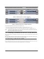
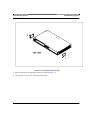
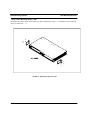
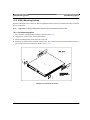
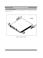
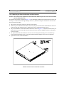
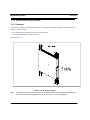
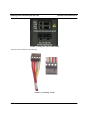
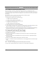
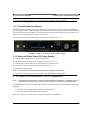
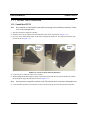
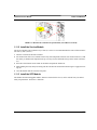
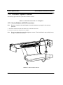
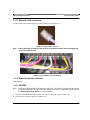
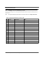
Allied Telesyn™ 910x
integrated Multiservice Access Platform
Installation Guide
Release 7.0 (and up unless reissued)
Issue 1
© 2005 Allied Telesyn Networks. All rights reserved. Information subject to change without notice.
Introduction
Congratulations on your purchase of a Allied Telesyn™ 910x, integrated Multiservice Access Platform
(iMAP) product. This product is part of a family of products that leverages Ethernet switching technology to
offer service providers a range of services, including video over xDSL.
Who Should Read This Guide?
This document provides an outline for installation and turn up of the Allied Telesyn 910x product, from the
unpacking of materials to setting up the initial user interface. The product is then ready to be introduced to
the network.
About this Guide
This guide includes
•
Section 1 provides step-by-step instructions for installing the Allied Telesyn 910x, from unpacking the
chassis to monitoring initialization from the local (CONSOLE) interface.
•
The Appendix gives a list of Glossary Terms as well as a worksheet for office records.
Reason for Update
This is the first release for this product.
© 2005 Allied Telesyn Networks. All rights reserved. Information subject to change without notice.
Table of Contents
1 Installation of Allied Telesyn 9100- - - - - - - - - - - - - - - - - - -1-1
1.1 Installation Overview for the 9100 - - - - - - - - - - - - - - - - - - - - - - - - - - - - - - - - - - - - - - 1-1
1.1.1 Allied Telesyn 9100 Configuration - - - - - - - - - - - - - - - - - - - - - - - - - - - - - - - - - - 1-1
1.2 Following Procedures for the 9101, 9102, and 9103 - - - - - - - - - - - - - - - - - - - - - - - - - - 1-2
1.3 Selecting a Site for the 9100- - - - - - - - - - - - - - - - - - - - - - - - - - - - - - - - - - - - - - - - - - - 1-2
1.3.1 9101 Site Requirements- - - - - - - - - - - - - - - - - - - - - - - - - - - - - - - - - - - - - - - - - - 1-3
1.3.2 9102/9103 Site Requirements- - - - - - - - - - - - - - - - - - - - - - - - - - - - - - - - - - - - - - 1-4
1.4 Setup Checklist - - - - - - - - - - - - - - - - - - - - - - - - - - - - - - - - - - - - - - - - - - - - - - - - - - - 1-6
1.4.1 9101 Parts Included in Order - - - - - - - - - - - - - - - - - - - - - - - - - - - - - - - - - - - - - - 1-6
1.4.2 9102 / 9103 Parts Included in Order - - - - - - - - - - - - - - - - - - - - - - - - - - - - - - - - - 1-7
1.5 Shelf Mounting Options - - - - - - - - - - - - - - - - - - - - - - - - - - - - - - - - - - - - - - - - - - - - - 1-8
1.5.1 9101 Mounting Options- - - - - - - - - - - - - - - - - - - - - - - - - - - - - - - - - - - - - - - - - - 1-8
1.5.2 9102/3 Mounting Options - - - - - - - - - - - - - - - - - - - - - - - - - - - - - - - - - - - - - - - 1-11
1.6 Wall Mounting Option - - - - - - - - - - - - - - - - - - - - - - - - - - - - - - - - - - - - - - - - - - - - - 1-14
1.6.1 Overview - - - - - - - - - - - - - - - - - - - - - - - - - - - - - - - - - - - - - - - - - - - - - - - - - - 1-14
1.6.2 Installing the Wall Mount - - - - - - - - - - - - - - - - - - - - - - - - - - - - - - - - - - - - - - - 1-15
1.7 Allied Telesyn 9100 Installation Safety - - - - - - - - - - - - - - - - - - - - - - - - - - - - - - - - - 1.7.1 Safety Guidelines - - - - - - - - - - - - - - - - - - - - - - - - - - - - - - - - - - - - - - - - - - - - 1.7.2 Safety Precautions While Working with Electricity - - - - - - - - - - - - - - - - - - - - - 1.7.3 Electrostatic Discharge - - - - - - - - - - - - - - - - - - - - - - - - - - - - - - - - - - - - - - - - 1.7.4 Precautions and Conformance Standards - - - - - - - - - - - - - - - - - - - - - - - - - - - - 1.7.5 Laser Safety Instructions - - - - - - - - - - - - - - - - - - - - - - - - - - - - - - - - - - - - - - - -
1-15
1-15
1-16
1-16
1-17
1-18
1.8 Installing Power and Ground for the 9101 - - - - - - - - - - - - - - - - - - - - - - - - - - - - - - 1.8.1 Power and Grounding Cautions - - - - - - - - - - - - - - - - - - - - - - - - - - - - - - - - - - 1.8.2 Connect Power and Ground - - - - - - - - - - - - - - - - - - - - - - - - - - - - - - - - - - - - - 1.8.3 Connect the -48VDC office power supply to the 9101 PEM plug. - - - - - - - - - - - 1.8.4 Connect to Power Source (Single or Dual) - - - - - - - - - - - - - - - - - - - - - - - - - - - 1.8.5 Apply and Check Power (DC Power Supply) - - - - - - - - - - - - - - - - - - - - - - - - - -
1-18
1-18
1-19
1-21
1-22
1-22
1.9 Installing Power and Ground for the 9102 - - - - - - - - - - - - - - - - - - - - - - - - - - - - - - - 1-23
1.9.1 Connect Power and Ground - - - - - - - - - - - - - - - - - - - - - - - - - - - - - - - - - - - - - - 1-23
1.9.2 Apply and Check Power (AC Power Supply) - - - - - - - - - - - - - - - - - - - - - - - - - - 1-23
1.10 Alarm Connections - 9101 (Optional) - - - - - - - - - - - - - - - - - - - - - - - - - - - - - - - - - - 1-23
1.11 Install Card Modules - - - - - - - - - - - - - - - - - - - - - - - - - - - - - - - - - - - - - - - - - - - - - 1-24
Telesyn 9100 Installation Guide (Table of Contents)
1.11.1
1.11.2
1.11.3
1.11.4
Install the CFC12- - - - - - - - - - - - - - - - - - - - - - - - - - - - - - - - - - - - - - - - - - - - - 1-24
Install the Service Module- - - - - - - - - - - - - - - - - - - - - - - - - - - - - - - - - - - - - - - 1-25
Install the SFP Module - - - - - - - - - - - - - - - - - - - - - - - - - - - - - - - - - - - - - - - - - 1-25
Install Filler Plates (FPF) - - - - - - - - - - - - - - - - - - - - - - - - - - - - - - - - - - - - - - - 1-26
1.12 Configure Local Terminal or PC- - - - - - - - - - - - - - - - - - - - - - - - - - - - - - - - - - - - - - 1-26
1.13 Connect System Cables - - - - - - - - - - - - - - - - - - - - - - - - - - - - - - - - - - - - - - - - - - - - 1-28
1.13.1 Service Modules with RJ21connectors - - - - - - - - - - - - - - - - - - - - - - - - - - - - - - 1-28
1.13.2 SMs with RJ45 connectors - - - - - - - - - - - - - - - - - - - - - - - - - - - - - - - - - - - - - - 1-29
1.13.3 SMs with Optical connectors - - - - - - - - - - - - - - - - - - - - - - - - - - - - - - - - - - - - - 1-29
1.13.4 GE4/FE2 - - - - - - - - - - - - - - - - - - - - - - - - - - - - - - - - - - - - - - - - - - - - - - - - - - 1-29
1.13.5 Data Management Cable (MGMT Port on CFC12) - - - - - - - - - - - - - - - - - - - - - - 1-30
1.14 Apply Power and Check Startup Sequence - - - - - - - - - - - - - - - - - - - - - - - - - - - - - - 1-31
1.15 Check the configuration - - - - - - - - - - - - - - - - - - - - - - - - - - - - - - - - - - - - - - - - - - - - 1-33
1.15.1 Check software load- - - - - - - - - - - - - - - - - - - - - - - - - - - - - - - - - - - - - - - - - - - 1-33
1.15.2 Check management interfaces - - - - - - - - - - - - - - - - - - - - - - - - - - - - - - - - - - - - 1-33
1.16 Adding AC Power Module - - - - - - - - - - - - - - - - - - - - - - - - - - - - - - - - - - - - - - - - - - 1-34
1.17 Allied Telesyn Contact Information- - - - - - - - - - - - - - - - - - - - - - - - - - - - - - - - - - - - 1-34
2 Appendix - - - - - - - - - - - - - - - - - - - - - - - - - - - - - - - - - - - 2-1
2.1 Glossary of Terms - - - - - - - - - - - - - - - - - - - - - - - - - - - - - - - - - - - - - - - - - - - - - - - - - -2-1
2.2 Telesyn 9100 Inventory Form - - - - - - - - - - - - - - - - - - - - - - - - - - - - - - - - - - - - - - - - - -2-2
TOC-2
Telesyn User Guide (Table of Contents)
1. Installation of Allied Telesyn 9100
1.1 Installation Overview for the 9100
1.1.1 Allied Telesyn 9100 Configuration
The Allied Telesyn™ 9100 is shelf mounted with one Central Fabric Controller (CFC12) and Service Modules
(SMs) that depend on customer requirements. (Refer to the Allied Telesyn iMAP Component Specification for
which SMs can be used.)
Table 1-1, Figure 1-1, and Figure 1-2 show the Allied Telesyn 9100 components. Refer to these when performing any task in this document.
The 9100 is offered in these versions:
1.
The 9101-A has dual -48VDC power inputs.
2.
The 9102-A has a non-redundant AC power supply.
3.
The 9103-A has a redundant AC power supply.
TABLE 1-1
Listing of components for the 9101 with slot/position and configuration notes
Ref.
Module
Configuration Notes
A
CFC12 - Slot 3
Always provisioned with the CFC12 card and always in slot 3
B
SM slots (0, 1, 2)
At least one is provisioned with an SM card
C
PEM (9101 only)
Power connections. Provides system power and grounding. Includes power feeds A and
B, ground, common return, and fuses A and B. Not on the 9102/3
D
Console
Provides local connection to PC (RS232)
E
MGMT
Provides connection to ethernet management port (100BaseT)
F
GE2RJ
Provides Fast Ethernet to a close proximity, lower data rate (100M) Ethernet, as well as
1000BaseT
G
GE4
Provides copper or fiber 1-Gigabit Ethernet uplink interface to WAN. Small Form Factor
Pluggable (SFP) modules are required
Back of 9101 unit:
Provides external system alarming functions. ALM IN port and ALM OUT port
ALM IN, ALM OUT
Telesyn 9100 Installation Guide (Installation of Allied Telesyn 9100)
1-1
Following Procedures for the 9101, 9102, and 9103
Allied Telesyn 9100 Configuration
[
FIGURE 1-1
FIGURE 1-2
Allied Telesyn 9101 - Example Configuration
Allied Telesyn 9102 / 9103 - Example Configuration
Note the following differences between the 9102/3 and the 9101:
• The 9102/3 is deeper and so has different environment / mounting options (refer to 1.5.2).
• Power and Grounding for the 9102/3 is for an AC Power Supply, and so there is no PEM (refer to 1.9).
Note:
The AC Power Supply Module must have power input that meets specifications listed in the
Allied Telesyn MAP Component Specification.
1.2 Following Procedures for the 9101, 9102, and 9103
Most of the procedures for installing the 9100 product are the same, with the main difference the options for providing power.
Most steps in this Guide apply to all three product types and are referred to as the 9100 product. When a procedure is specifically for a 9101, 9102, or 9103, there is a separate heading.
1.3 Selecting a Site for the 9100
Before installing the Allied Telesyn 9101, prepare the site to ensure the product will operate in the correct environment, all materials meet specifications, and all installation tasks can be performed.
1-2
Telesyn 9100 Installation Guide (Installation of Allied Telesyn 9100)
9101 Site Requirements
Selecting a Site for the 9100
1.3.1 9101 Site Requirements
The Allied Telesyn 9101 is installed in a environment that is affected by the existing installed equipment and the
specific requirements of the Allied Telesyn 9101 shelf. Refer to Table 1-2.
TABLE 1-2
Site Requirements for Allied Telesyn 9101
Type
Description
Access (for security reasons)
Installation in a restricted access location is preferred.
System Rear Access
Needed if the ALM IN and ALM OUT is going to be installed (during or
after initial installation).
Installation Placement
Placement: follow local cabling setup (from above, below, etc.)
Care should be taken not to compromise the stability of the rack by the
installation of this equipment.
Note: Due to weight limitations and the size of bundled cabling, 21 units can
physically be installed in a single 7 ft. telecom rack. However, the user
should verify that the floor loading for the rack, with the required number of
units installed, does not exceed the floor loading standard for the region or
country where the 9101(s) is being installed. 9101 installations inside the
U.S. would follow the Bellcore (Telcordia) floor loading standard of 114.7
lb. per square foot. See the Allied Telesyn Component Specification for the
NEBS specification.
Power Supply
Spacing
Connect to a reliable grounded 48VDC source. The branch circuit overcurrent protection must be rated 15 amp maximum, following NEC requirements for permanent office equipment.
Refer to Figure 1-3 for installation spacing and numbers:
1. Mounting Width Aperture: 19.7 in (500 mm) min.
2. Aperture between mounting flanges:
- 17.5 in (442 mm) for all mounting options
3. Total Shelf Depth: 11.8 in (300 mm):
a. Door or cover: .4 in (10 mm) (Front and Back)
b. In front of Reference Plane for equipment (i.e. subracks): 1.6 in (41
mm)
c. Behind Reference Plane: 9.5 in (241 mm)
4. Rack Pitch (Midpoint to Midpoint of each chassis): 25.6 in (650 mm)
Telesyn 9100 Installation Guide (Installation of Allied Telesyn 9100)
1-3
Selecting a Site for the 9100
9102/9103 Site Requirements
1.3.2 9102/9103 Site Requirements
The Allied Telesyn 9101 is installed in a environment that is affected by the existing installed equipment and the
specific requirements of the Allied Telesyn 9102/9103 shelf. Refer to Table 1-3.
TABLE 1-3
Site Requirements for Allied Telesyn 9102 / 9103
Type
Description
Number of people
Two people are required when mounting the shelf.
Access (for security reasons)
Installation in a restricted access location is preferred.
System Rear Access
Required, for power supply cord and grounding access, and to install /
remove power converters.
Installation Placement
Placement: follow local cabling setup (from above, below, etc.)
Care should be taken not to compromise the stability of the rack by the
installation of this equipment.
Note: Due to weight limitations and the size of bundled cabling, 21 units can
physically be installed in a single 7 ft. telecom rack. However, the user
should verify that the floor loading for the rack, with the required number of
units installed, does not exceed the floor loading standard for the region or
country where the 9101(s) is being installed. 9101 installations inside the
U.S. would follow the Bellcore (Telcordia) floor loading standard of 114.7
lb. per square foot. See the Allied Telesyn Component Specification for the
NEBS specification.
Power Supply
Spacing
120/220V, 50/60Hz
Refer to Figure 1-3 for installation spacing and numbers:
1. Mounting Width Aperture: 19.7 in (500 mm) min.
2. Aperture between mounting flanges:
- 17.4 in (442 mm) for all mounting options
3. Total Shelf Depth: 23.8 in (605 mm):
a. Door or cover: .4 in (10 mm) (Front and Back)
b. In front of Reference Plane for equipment (i.e. subracks): 1.6 in (41
mm)
c. Behind Reference Plane:21.5 in (545 mm)a
4. Rack Pitch (Midpoint to Midpoint of each chassis): 25.6 in (650 mm)
a. For front mount, the minimum space (depth) between the mounting brackets is 545 mm. For mid mount,
the minimum space (depth) between the mounting brackets is 485 mm. The extension and rear mounting
brackets allow for more depth if needed.
1-4
Telesyn 9100 Installation Guide (Installation of Allied Telesyn 9100)
9102/9103 Site Requirements
FIGURE 1-3
Selecting a Site for the 9100
Telesyn 9100 Space Requirements for Open Rack Environment (Table 1-2 and Table 1-3)
Telesyn 9100 Installation Guide (Installation of Allied Telesyn 9100)
1-5
Setup Checklist
9101 Parts Included in Order
1.4 Setup Checklist
1.4.1 9101 Parts Included in Order
Allied Telesyn provides and ships certain parts with each order.
Table 1-4 lists the items that are shipped with the 9101
Note:
If any of these items are not included, contact your local Allied Telesyn representative
TABLE 1-4
Check
Item
Part Checklist for 9101
Description
___
9101 Chassis
___
Brackets, Front Mount (2pcs) with screws for attaching brackets to chassis
___
Brackets, 19” to 23” Adapter (2pcs) with screws for attaching brackets to chassis
___
Fuses, 7.5A (4pcs); fuse holder (2pcs); DC Power Plug (1pc)
___
Shelf Mounting Kit, Metric, for attaching the chassis to a metric rack or cabinet (M6 screws)
___
Shelf Mounting Kit, Imperial, for attaching the chassis to an imperial rack or cabinet (#12-24
screws)
Table 1-5 lists the items that are to be provided by the customer.
TABLE 1-5
Customer Item Checklist
Item
Quantity
Description
MGMT
cable
1
RJ-45, connectorized, Cat 5
Power
Cabling
As
required
Length determined by shelf position and how cabling is routed
Voltmeter
1
Used to check the voltage at the terminal block
Console
cable
1
RJ-45, connectorized, Cat 5
cable ties
As needed
1-6
Used to connect local PC/terminal for local interface (RS232). Refer to 1.12.
n/a
Telesyn 9100 Installation Guide (Installation of Allied Telesyn 9100)
9102 / 9103 Parts Included in Order
Setup Checklist
1.4.2 9102 / 9103 Parts Included in Order
Table 1-6 lists the items that are shipped with the 9102.
Note:
If any of these items are not included, contact your local Allied Telesyn representative.
TABLE 1-6
Check
Item
Part Checklist for 9102
Description
___
9102 Chassis, equipped with (1pc) AC Power Supply and (1pc) Power Supply Filler Plate
___
AC Power Cord (1pc) for NA, UK, Australia/New Zealand, or EU depending on model selected
___
Brackets, Front Mount (2pcs) with screws for attaching brackets to chassis
___
Brackets, Rear Mount (2pcs) with screws for attaching brackets to chassis
___
Brackets, Rear Extension (2pcs) for extending the Rear Mount Brackets behind the chassis
___
Brackets, 19” to 23” Adapter (4pcs) with screws for attaching brackets to chassis
___
Shelf Mounting Kit, Metric, for attaching the chassis to a metric rack or cabinet (M6 screws)
___
Shelf Mounting Kit, Imperial, for attaching the chassis to an imperial rack or cabinet (#12-24
screws)
Table 1-7 lists the items that are shipped with the 9103.
Note:
If any of these items are not included, contact your local Allied Telesyn representative.
TABLE 1-7
Check
Item
Part Checklist for 9103
Description
___
9103 Chassis, equipped with (2pcs) AC Power Supply
___
AC Power Cord (2pc) for NA, UK, Australia/New Zealand, or EU depending on model selected
___
Brackets, Front Mount (2pcs) with screws for attaching brackets to chassis
___
Brackets, Rear Mount (2pcs) with screws for attaching brackets to chassis
___
Brackets, Rear Extension (2pcs) for extending the Rear Mount Brackets behind the chassis
___
Brackets, 19” to 23” Adapter (4pcs) with screws for attaching brackets to chassis
___
Shelf Mounting Kit, Metric, for attaching the chassis to a metric rack or cabinet (M6 screws)
___
Shelf Mounting Kit, Imperial, for attaching the chassis to an imperial rack or cabinet (#12-24
screws)
Telesyn 9100 Installation Guide (Installation of Allied Telesyn 9100)
1-7
Shelf Mounting Options
9101 Mounting Options
Table 1-8 lists the items that are to be provided by the customer.
TABLE 1-8
Customer Item Checklist
Item
Quantity
Description
OAM cable
1
RJ-45, connectorized, Cat 5
Power
Cabling
1
Standard AC cable (3 prong)
Console
cable
1
RJ-45, connectorized, Cat 5
cable ties
As needed
Used to connect local PC/terminal for local interface (usually through an RJ45 to RS232 converter)
Note - so issue of line isolation resolved?
n/a
1.5 Shelf Mounting Options
Three mounting options are available for the 9101; front, center, and wall.
Note:
The wall mounting option is explained in a separate section, 1.6.
1.5.1 9101 Mounting Options
1.5.1.1 Front Mounting Option
The bracket is mounted on the front of the 9101 unit as illustrated in Figure 1-4.
1-8
Telesyn 9100 Installation Guide (Installation of Allied Telesyn 9100)
9101 Mounting Options
Shelf Mounting Options
FIGURE 1-4
Front mount option for 9101
1.
Place the brackets in the appropriate location as shown in Figure 1-4.
2.
Using the M3 x 6mm screws, mount the front brackets.
Telesyn 9100 Installation Guide (Installation of Allied Telesyn 9100)
1-9
Shelf Mounting Options
9101 Mounting Options
1.5.1.2 Center Mounting Option - 9101
The bracket is mounted on the center of the 9101 unit as illustrated in Figure 1-5. Mount the bracket following
the steps of Section 1.5.1.1.
FIGURE 1-5
1-10
Mid-mount option for 9101
Telesyn 9100 Installation Guide (Installation of Allied Telesyn 9100)
9102/3 Mounting Options
Shelf Mounting Options
1.5.2 9102/3 Mounting Options
Because of the depth of the 9102/3 unit, there are adjustable bracket extensions, and attached to these extensions
are the rear brackets.
Note:
Regardless of the mounting option chosen, the rear brackets must be used.
1.5.2.1 Front Mounting Option
1.
Place a bracket in the appropriate location as shown in Figure 1-6.
2.
Using the M3 x 6mm screws, mount a front bracket.
3.
Install a mounting bracket on the other side of the unit.
4.
Install the extension brackets using M4 x 6mm screws. The extension bracket should be installed so that it is
just in front of the rear mounting rail. (Refer to Figure 1-8.)
FIGURE 1-6
Front Mount for 9102/3
Telesyn 9100 Installation Guide (Installation of Allied Telesyn 9100)
1-11
Shelf Mounting Options
9102/3 Mounting Options
1.5.2.2 Center Mounting Option
The bracket is mounted on the center of the 9101 unit as illustrated in Figure 1-7. Mount the brackets following
the steps of Section 1.5.2.1.
FIGURE 1-7
1-12
Mid-Mount for 9102/3
Telesyn 9100 Installation Guide (Installation of Allied Telesyn 9100)
9102/3 Mounting Options
Shelf Mounting Options
1.5.2.3 Attaching the Extension Brackets and Rear Brackets
Caution: Two persons are required to mount the 9102/3, with one person in front of and another
person behind the unit.
Note that the rear brackets, as shown in Figure 1-8, are rotationally symmetrical; when facing the rear of the unit,
the flange is on the bottom on the right, and top on the left. (This allows adequate clearance for removal of the
power converter if needed.)
1.
The person in front of the unit moves the 9102/3 into position.
2.
While the person behind the unit holds the unit steady, the person in front of the unit attaches the unit to the
front rack using four mounting screws. (Install the top screws and then the bottom screws.)
3.
The person behind the unit attaches the Rear Brackets as shown in Figure 1-8. Adjust the brackets so they are
flush with the rear rack. Attach the four nuts loosely since they will move slightly when the rear mounting
screws are turned.
4.
The person behind the unit attaches the unit to the rear rack using four mounting screws. (Install the top
screws and then the bottom screws.). The rear bracket should slide slightly as the screws are tightened.
5.
Tighten the four nuts of the Rear Bracket.
FIGURE 1-8
Rear Bracket Attachment for 9102/3
Telesyn 9100 Installation Guide (Installation of Allied Telesyn 9100)
1-13
Wall Mounting Option
Overview
1.6 Wall Mounting Option
1.6.1 Overview
If the customer wishes to wall mount the unit, there is a separate kit available through an Allied Telesyn representative. This kit includes:
• Four brackets that are attached to the unit, two for each side
• Screws for attaching the brackets to the unit.
Refer to Figure 1-9.
FIGURE 1-9
Note:
1-14
Wall Mounting Option
The wall mount kit does not include the screws/bolts that are used to attach the brackets to a
wall. The brackets are designed to use M4 or #8 screws, or bolts if appropriate.
Telesyn 9100 Installation Guide (Installation of Allied Telesyn 9100)
Installing the Wall Mount
Allied Telesyn 9100 Installation Safety
Caution: The customer must ensure that the weight of a fully configured unit can be supported
by the mounting hardware/support used with the brackets.
1.6.2 Installing the Wall Mount
1.
Ensure there is enough space for the unit and associated cables
2.
Screw the brackets to the sides of the unit using the screws supplied in the kit.
3.
Locate and mark on the wall where the two holes where the top brackets will be mounted. Ensure the marks
are horizontal.
4.
Install two anchor screws/bolts, one for each top bracket.
5.
Hang the unit from these anchors
6.
Install the two bottom anchor screws/bolts, one through each bottom bracket.
7.
Tighten all anchor screws/bolts and bracket screws.
1.7 Allied Telesyn 9100 Installation Safety
1.7.1 Safety Guidelines
Note:
Only personnel familiar with local telco practices should install, replace, or service this
equipment.
Note:
Before starting the installation procedures, the user should read all of this section for important
safety information and warnings.
Before installing and cabling the equipment, the user should be aware
of standard safety practices and the hazards involved in working with
electricity to avoid accidents. See the following section, Safety Guidelines, for all cautions and warnings to insure that the installation is safe
and free of hazards.
Before working on the equipment, the user should be aware of standard safety guidelines and the hazards
involved in working with electricity to avoid accidents. Follow these guidelines and warnings and those located
throughout this installation guide for a safe and hazard-free installation.
Follow these guidelines to ensure overall safety:
•
•
•
•
The user should keep all work areas clear and clean during and after installation.
The user should keep all tools away from walk areas where personnel could trip over them.
The user should not wear loose clothing that could catch on equipment. Secure any loose clothing.
The user should wear safety glasses if working under conditions that might be hazardous to eyes.
Telesyn 9100 Installation Guide (Installation of Allied Telesyn 9100)
1-15
Allied Telesyn 9100 Installation Safety
Safety Precautions While Working with Electricity
• The user should not perform any action that creates an unsafe or hazardous situation for themselves or other
personnel.
1.7.2 Safety Precautions While Working with Electricity
Guidelines when working with electrically powered equipment:
• Locate the Power Off switch for the system being installed or serviced. In the event of an electrical accident,
the user can quickly turn the power off.
• Disconnect all power by turning the circuit breakers off before:
• Installing or removing a chassis
• Working near the power supply
• Do not work alone if potential hazards exist.
• Never assume that power is disconnected from a circuit; always check the circuit.
• Inspect the work area carefully for possible hazards, such as moist floors, moist or wet ground, ungrounded
power extension cables, frayed power cords, and missing safety grounds.
• If an electrical accident occurs, proceed as follows:
• Use caution; do not become a victim yourself.
• Turn off power to the system.
• If possible, send another person to get medical aid. Otherwise, assess the condition of the victim and then
call for help.
• Determine if the person needs rescue breathing or external cardiac compressions; then, take appropriate
action.
Ensure customer power source for the product is off.
Ensure that fuses A and B on the 9100 are removed.
1.7.3 Electrostatic Discharge
Electrostatic discharge (ESD) can damage equipment when electronic equipment is handled improperly. ESD
damage can produce total or partial failures in electronic equipment. Follow these ESD-prevention procedures
when handling systems cards and modules. Follow this procedure:
1.
Verify that the frame is electrically connected to earth ground.
2.
Wear an ESD-preventive device such as a foot strap or wrist strap, ensuring that it makes good contact
with the user’s skin. If a foot strap is being used, the floor must be ESD conductive.
1-16
Telesyn 9100 Installation Guide (Installation of Allied Telesyn 9100)
Precautions and Conformance Standards
Allied Telesyn 9100 Installation Safety
3.
Connect the clip from the ESD-preventative device to an unpainted surface of the frame, rack or ESD
point on the chassis frame connecting it directly to ground. This ensures that unwanted ESD voltages
safely flow to ground.
4.
Wear the ESD-preventive device correctly to properly guard against ESD damage and shock. If no foot or
wrist strap is available, the user should ground themselves by making contact with an unpainted, metal
part of the chassis.
1.7.4 Precautions and Conformance Standards
FCC - The Allied Telesyn 9101/9102/9103 product complies with FCC
requirements for emissions radiation. Users of the Allied Telesyn 9101/
9102/9103 product are cautioned that any changes or modifications not
expressly approved by the party responsible for FCC compliance could
void the user’s authority to operate the product.
ALL COUNTRIES: Install product in accordance with local and
National Electrical Codes.
This equipment conforms to the following European Community standards:
• EN55022: 1998 Information Technology Equipment—Radio disturbance
• EN55024: 1998 Information Technology Equipment—Immunity characteristics—Limits and methods of
measurement.
• EN60950: 2000 Safety of Information Technology Equipment, including electrical business equipment.
• EN60825-1: 1994 Safety of Laser Products - part 1: Equipment classification, requirements and user’s
guide.
• EN61000-3-2: 1995 Electromagnetic compatibility (EMC) - part 3-2: Limits for harmonic current emissions (equipment input current up to and including 16A per phase).
• EN61000-3-3: 1995 Electromagnetic compatibility (EMC) - part 3-3: Limitation of voltage fluctuations
and flicker in low-voltage supply systems for equipment with rated current up to 16A
Telesyn 9100 Installation Guide (Installation of Allied Telesyn 9100)
1-17
Installing Power and Ground for the 9101
Laser Safety Instructions
1.7.5 Laser Safety Instructions
Complies with FDA radiation performance standards, 21 CFR Subchapter J.
Use of controls or adjustments or performance of procedures other
than those specified herein may result in hazardous radiation exposure.
Complies with 21 CFR 1040.10 and 1040.11.
1.8 Installing Power and Ground for the 9101
1.8.1 Power and Grounding Cautions
Power and the primary ground for the Allied Telesyn 9101 shelf is provided by the power entry module plug and
originates at the office ground.
This equipment is designed to permit the connection of the earthed conductor of the D.C. supply circuit to the earthing conductor at the equipment.
If this connection is made, all four of the following conditions must be met:
1.
2.
3.
4.
1-18
This equipment shall be connected directly to the D.C. supply system
earthing electrode conductor or to a bonding jumper from an earthing
terminal bar or bus to which the D.C. supply system earthing electrode
conductor is connected.
This equipment shall be located in the same immediate area (such as,
adjacent cabinets) as any other equipment that has a connection between
the earthed conductor of the same D.C. supply circuit and the earthing
conductor, and also the point of earthing of the D.C. system. The D.C.
system shall not be earthed elsewhere.
The D.C. supply source is to be located within the same premises as the
equipment.
There shall be no switching or disconnecting devices in the earthed circuit conductor between the D.C. source and the point of connection of
the earthing electrode conductor.
Telesyn 9100 Installation Guide (Installation of Allied Telesyn 9100)
Connect Power and Ground
Installing Power and Ground for the 9101
The separate protective earthing terminal provided on this product shall be
permanently connected to earth.
Before connecting any power (or grounding) cable, ensure the following:
1.
Connect to a reliably grounded 48VDC SELV (Safety Extra Low Voltage) source.
(SELV - UL60950 - A circuit designed so that its voltages do not exceed a normal
and fault value of 42.4 Vpeak or 60 VDC.)
2.
The branch circuit overcurrent protection must be rated 15A.
3.
A readily accessible disconnect device that is suitably approved and rated shall be
incorporated in the field wiring.
4.
The customer-provided power (-48VDC) is off (visibly disconnected) and the
Allied Telesyn 9100 fuses are removed.
5.
Use 14 AWG copper conductors.
Earth grounding conductors must have green/yellow insulation.
6.
1.8.2 Connect Power and Ground
The Allied Telesyn 9101 is shipped with a power entry module plug. The user connects power and ground to this
plug, plugs it into the 9101 power entry module (PEM), then turns on office power which applies power to the
plug. The user then inserts the plug into the 9101 PEM. Finally, the user inserts fuses A and B to power the unit.
The following text and diagrams describe how to wire the 9100 for power and ground.
Slots for Fuse A and Fuse B are located above the plug. Notice the connections for -48 A, -48 B, ground
RTN. The PEM plug will be inserted into this connector. See Figure 1-10.
Note:
, and
To provide redundancy for the RTN, the user can to insert one wire into the RTN connector
position, and then after some distance, use a butt splice, wire connector, T-splice, etc. to split it
into two wires. This configures a wire to the A feed and a wire to the B feed and creates
redundancy.
Telesyn 9100 Installation Guide (Installation of Allied Telesyn 9100)
1-19
Installing Power and Ground for the 9101
FIGURE 1-10
Connect Power and Ground
9101 power entry module (PEM)
The figure below details the 9100 PEM plug.
FIGURE 1-11
1-20
PEM Plug - Details
Telesyn 9100 Installation Guide (Installation of Allied Telesyn 9100)
Connect the -48VDC office power supply to the 9101 PEM plug. Installing Power and Ground for the 9101
1.8.3 Connect the -48VDC office power supply to the 9101 PEM plug.
1.
Loosen the screws.
2.
Using cables colored as in Figure 1-12, strip each 1/4 in. (6.5 mm).
3.
Insert each cable into its appropriate lug on the PEM plug. Use the figure below to determine the correct lugs.
FIGURE 1-12
9100 PEM plug with connections indicated
4.
Tighten each screw.
5.
Carefully dress and tie-wrap or tape the power and ground cables.
6.
Ensure that fuses A and B have been removed from the 9100 PEM.
7.
Plug the 9100 PEM plug into its connector on the faceplate of the unit. The PEM plug will only fit one way.
Tabs on the front of the PEM plug prevent it from being inserted incorrectly.
Telesyn 9100 Installation Guide (Installation of Allied Telesyn 9100)
1-21
Installing Power and Ground for the 9101
Connect to Power Source (Single or Dual)
1.8.4 Connect to Power Source (Single or Dual)
The user can decide to connect the A and B feeds to a single power source or a different power source.
If the customer chooses to use a single power source, jumper the -48 A and -48 B feeds together. Allied Telesyn
recommends that separate cables be run from the single power source and return to each of the specified lugs on
the PEM plug.
With a dual power source, if one power source fails, the shelf can continue to operate.
The different steps are included in the procedure below:
1.
2.
If connection to a dual power source, follow these steps.
1.
Connect -48 A to a -48 VDC source.
2.
Connect -48 B to a different -48 VDC source.
If connecting to a single power source, follow these steps:
1.
Connect -48 A to a -48 VDC source.
2.
Connect -48 B to the same -48 VDC source.
3.
Connect the ground
wire to the frame grounding point.
4.
Connect the RTN to a common return, or split the wire from the RTN after some distance and then use a butt
splice, wire connector, T-splice, etc. to split it into two wires. Refer to the Note in 1.8.2.
5.
Plug the 9101 PEM plug into its connector on the faceplate of the unit. As mentioned before, the PEM plug
will only fit one way. Tabs on the front of the PEM plug prevent it from being inserted incorrectly.
1.8.5 Apply and Check Power (DC Power Supply)
1.
Ensure that fuses A and B have been removed from the 9100 PEM.
2.
Turn ON the DC power source.
3.
Measure the voltage between -48 A and RTN A screws on the power connector. -48A should be negative
with respect to RTN.
4.
Measure the voltage between -48 B and RTN B screws on the power connector. -48 B should be negative
with respect to RTN.
5.
Measure -48 A to GND. Should be -48VDC negative with respect to GND.
6.
Insert Fuse A, and then Fuse B into the 9100 PEM. Power is now being applied to the 9100 unit and components.
7.
The fans will start to operate.
Note:
8.
Fan speed is self-regulating and will automatically adjust as necessary.
Remove Fuse A and B to disconnect power from the 9101. The card modules are installed next.
1-22
Telesyn 9100 Installation Guide (Installation of Allied Telesyn 9100)
Connect Power and Ground
Installing Power and Ground for the 9102
1.9 Installing Power and Ground for the 9102
1.9.1 Connect Power and Ground
The Allied Telesyn 9102 comes with a pre-installed AC power converter. (The 9103 comes with redundant AC
power converters.) With 14 AWG grounding wire (green/yellow insulation), the user connects the ground stud at
the rear of the unit to Frame ground. The user then connects the power cord from the AC power outlet to the AC
power converter and then turns the AC power converter on.
The AC power converter is located at the rear of the unit, as shown in Figure 1-13.
FIGURE 1-13
9102 / 3 AC Power Converter (Rear of Unit)
1.9.2 Apply and Check Power (AC Power Supply)
1.
Using 14 AWG grounding wire, connect the ground stud.
2.
Ensure the power converter is in the Off position - Refer to Figure 1-13.
3.
Using the power cord, connect the AC power unit to an AC power outlet.
4.
Set the power converter in the On position - Refer to Figure 1-13
5.
The fans will start to operate.
Note:
6.
Fan speed is self-regulating and will automatically adjust as necessary.
Set the power converter back to the Off position. The card modules are installed next.
1.10 Alarm Connections - 9101 (Optional)
Note:
Connecting the alarm cables is optional. After initial system installation is complete, the user
can return to this section and connect the alarm cables and configure the system alarms.
Two RJ-45 plugs are on the rear of the unit and are used as connecting cables for external alarms. Connect them
as follows:
• one RJ-45 used for alarm indicator input, into the ALM IN port
• one RJ-45 used for the ALM OUT port as required.
Refer to the Allied Telesyn iMAP Component Specification for more information.
Telesyn 9100 Installation Guide (Installation of Allied Telesyn 9100)
1-23
Install Card Modules
Install the CFC12
1.11 Install Card Modules
1.11.1 Install the CFC12
Note:
Do not attempt to install system cards without observing correct antistatic procedures. Failure
to do so may damage cards.
1.
Take the card from its antistatic container.
2.
Hold the card securely with the lock-latch and label on the inside of the chassis. (Figure 1-15)
3.
Press the release button on the inside of the latches and push the latches out. This puts the card in the open
position. Refer to Figure 1-15.
FIGURE 1-14
Latches in Open and Locked Position
4.
Locate the slot (3) where the card is to be inserted.
5.
While holding the latches/faceplate, slowly with a firm pressure push the card into the double slot until the
latches begin to engage the locking rail. Refer to Figure 1-15.
Note:
6.
A firm pressure is required to seat the card. The lock-latch does not assist in seating the card.
Close the latches until they lock into place.(You do not need to press the release button while doing this.)
1-24
Telesyn 9100 Installation Guide (Installation of Allied Telesyn 9100)
Install the Service Module
FIGURE 1-15
Install Card Modules
Detail of the card latch in Open Position (Card Below is Locked)
1.11.2 Install the Service Module
The Service Modules can be placed in any of slots 0, 1 and 2. It is recommended that the slots be filled in numerical order (0, then 1, then 2).
1.
Take the card from its antistatic container.
2.
For insertion into slots 0 or 2, hold the card securely with component side down. For insertion into slot 1, hold
the card by its latches with component side up. (For any slot, the latch/label will go on the inside of the chassis).
3.
Press the release buttons on the inside of the latches and push the latches out.
4.
While holding the card, slowly but firmly push the card into the slot until the latches begin to engage the locking rail.
5.
Close the latches until the card locks into place.
1.11.3 Install the SFP Module
The Small Form Factor Pluggable module, which are inserted in the CFC12, can be ordered from your Allied
Telesyn representative. Some have a bail latch.
Telesyn 9100 Installation Guide (Installation of Allied Telesyn 9100)
1-25
Configure Local Terminal or PC
Install Filler Plates (FPF)
1.11.4 Install Filler Plates (FPF)
The FPF is needed to keep dust from entering the chassis and to ensure
proper airflow. The shelf may overheat or become damaged if these are
not properly installed in every unused slot.
Do not allow the metal plate to touch the components of neighboring
cards.
While inserting the FPF, be careful not to get fingers pinched between
cards.
For the Allied Telesyn 9101/9102, and 9103, FPFs are installed in empty service module slots. To install the
FPF:
1.
Hold the FPF card securely and slowly but firmly push the card into the slot until the latches begin to engage
the locking rail.
Close the latches until the card locks into place
1.12 Configure Local Terminal or PC
The CONSOLE terminal port is used during the initial installation startup to connect the Telesyn 9101/9102/
9103 to a local management device, which can be:
• A terminal (VT-100 compatible)
• A PC with terminal emulation software
The CONSOLE port is an RJ45 connection (not a DB9 connection as is standard with are other Allied Telesyn
iMAP units). Pinout is as follows:
• Pin 3 -TXD
• Pin 6 - RXD
Pin 4 (or 5) - GND
The CONSOLE port is connected to a passthrough connector to provide a DB9 female socket configured as a
DCE, which allows for the direct connection to the terminal or PC.
The following modem control signals are not in the connector:
•
•
•
•
1-26
Clear To Send
Request To Send
Data Set Ready
Data Terminal Ready
Telesyn 9100 Installation Guide (Installation of Allied Telesyn 9100)
Install Filler Plates (FPF)
Configure Local Terminal or PC
• Carrier Detect
The settings for the CONSOLE port are factory configured with the following default values
Note:
When using the CONSOLE port, ensure that the terminal emulation software has FLOW
CONTROL disabled.:
TABLE 1-9
Default Asynchronous Port Settings
Option
Default
Option
Default
ATTENTION
BREAK
MAXOQLEN
0 (Unrestricted)
CDCONTROL
IGNORE
MTU
1500
DATABITS
8
NAME
ASYN 0
DEFAULTSERVICE
FALSE
OUTFLOW
HARDWARE
DTRCONTROL
ON
PAGE
22
ECHO
ON
PARITY
NONE
FLOW
HARDWARE
PROMPT
DEFAULT (CMD>)
HISTORY
30
SECURE
ON
INFLOW
HARDWARE
SERVICE
NONE
IPADDRESS
NONE
SPEED
9600
IPXNETWORK
NONE
STOPBITS
1
LOGIN
ON
TYPE
VT100
1.
Connect the RS-232 cable from the terminal or PC to an RS-232 passthrough device and then to the Allied
Telesyn 9100 CONSOLE port.
2.
If the device is a PC, bring up the terminal emulation window.
3.
Emulation settings are: 9600, 1 STOP, No flow, No parity, 8-bit data
Telesyn 9100 Installation Guide (Installation of Allied Telesyn 9100)
1-27
Connect System Cables
Service Modules with RJ21connectors
1.13 Connect System Cables
The following figure illustrates system cable connector locations.
FIGURE 1-16
9101 Cable Connections - To Be Supplied
1.13.1 Service Modules with RJ21connectors
Note:
Be sure to include in the cable length the overall maximum loop length to the customer
premises.
1.
Attach the connectorized end of the RJ21 cable to the RJ21 based card.
2.
Use the screw and a tie wrap to secure it in place.
Note:
Do not over-tighten the screw. Hand tighten to secure. Then install the tie wrap, pulling it snug
enough to secure the connector.
FIGURE 1-17
1-28
RJ-21 Cable Connector
Telesyn 9100 Installation Guide (Installation of Allied Telesyn 9100)
SMs with RJ45 connectors
Connect System Cables
1.13.2 SMs with RJ45 connectors
Attach the RJ45 end of the Ethernet cable to the specified port on the FE10 card.
FIGURE 1-18
Note:
FE10 Cable Connector
Each RJ45 cable connected to the FE10 card should be dressed neatly and tightly. Do
not permit cables to loop.
FIGURE 1-19
FE10 RJ45 Connector Dressing
1.13.3 SMs with Optical connectors
To Be Supplied
1.13.4 GE4/FE2
Note:
The 9100 is equipped with 2 FE ports and 4 GE ports. The first FE or GE port can be used as
the system uplink port. The other FE port or GE ports are used to support daisy-chaining. See
the Allied Telesyn User Guide for more information.
1.
Install the SFPs and attach the optical cable to the GE4 or connect the cable to the FE2 card.
2.
Attach the other end of the cable to the uplink device.
Telesyn 9100 Installation Guide (Installation of Allied Telesyn 9100)
1-29
Connect System Cables
Data Management Cable (MGMT Port on CFC12)
1.13.5 Data Management Cable (MGMT Port on CFC12)
Note:
Connect this cable only if the user plans to use the MGMT port for the management interface.
Refer to the Allied Telesyn User Guide, Chapter 3.
Connect one end of the ethernet cable to the MGMT port and connect the other end to a port that accesses the
TCP/IP network, as described in the Allied Telesyn User Guide, Chapter 3.
1-30
Telesyn 9100 Installation Guide (Installation of Allied Telesyn 9100)
Data Management Cable (MGMT Port on CFC12)
Apply Power and Check Startup Sequence
1.14 Apply Power and Check Startup Sequence
1.
For the 9101, insert Fuse A and then Fuse B into the 9101 PEM.
2.
For the 9102, set the AC Power Unit to the On position.
3.
Observe that the fans should start and airflow should be begin through the unit.
4.
Observe the startup sequence on the terminal interface, which should show the following:
Note:
The startup sequence the user observes on the terminal may not exactly match the one
illustrated below. However, it should be free from any error messages.
@@@@@@@@@@@@@@@@@@@@@@@@@@@@@@@@@@@@@@@@@@@@@@@@@@@@@@@@@@@@@@@@@@@@@@@@@@@
Allied Telesyn 12G Central Fabric Controller Boot Loader
Version 7.0.b.01.20050527
Created on Tue 05/31/2005 at 6:20p
Copyright Allied Telesyn Networks, Inc., 2004
VxWorks Version 5.5.1 for IBM PowerPC 440GP Rev. 2.0
BSP version 1.2/3
Copyright Wind River Systems, Inc., 1984-2002
@@@@@@@@@@@@@@@@@@@@@@@@@@@@@@@@@@@@@@@@@@@@@@@@@@@@@@@@@@@@@@@@@@@@@@@@@@@
FPGA Version 12.11
Starting Allied Telesyn Product Software Loading.
Attaching to Flash File System ... done.
/tffs/ - Volume is OK
Press any key to stop automatic loading of software image...
0
Automatically loading software image...
Boot album is (current, attempt 1): '/tffs/load/cfc12_7.0.0.alpha.20050720.tar'
Checking Album's integrity...done
Loading vxWorks.bin.gz...(7998464 bytes)
Starting at 0x10000...
Attaching interface lo0...done
Adding 51113 symbols for standalone.
@@@@@@@@@@@@@@@@@@@@@@@@@@@@@@@@@@@@@@@@@@@@@@@@@@@@@@@@@@@@@@@@@@@@@@@@@@@
;@ @@@@@@@@@@@@@@@@@ ====
,;@@@@ @@@@@@@@@@@@@@" ========
;@@@@@@@@
@@@@@@@@" ,@ ========
,;@@@@@@@@@@@ @@@@@@@" ,@@@ ========
;@@@@@@@@@@@@@@@ @@@@;" ,@@@@@@ ====,
,;@@@@@@@@@@" ;@@@@@ @@" @@@@@@@@@@@@"
Telesyn 9100 Installation Guide (Installation of Allied Telesyn 9100)
1-31
Apply Power and Check Startup Sequence
@@@@@@@@@@@"
Data Management Cable (MGMT Port on CFC12)
"@@@@@ " @@@@@@@@@@@@@"
Allied Telesyn Networks, Inc.
Allied Telesyn 12G Central Fabric Controller
Version 7.0.0.ALPHA.20050720 (Lab-Only Build)
Created on Wed 07/20/2005 at 4:46a
Copyright Allied Telesyn Networks, Inc., 2004
---------------------------------------------Software Version Information
---------------------------------------------Build name : Allied Telesyn 12G Central Fabric Controller
Build type : Lab-Only Build
Revision
: 7.0.0.ALPHA.20050720
Built on
: Wed 07/20/2005 at 4:46a
Built by
: ccbuild
Environment: ccbuild_R7.0_nightly_integration
Baseline
: Integration Latest
Target
: cfc12
Options
:
---------------------------------------------Boot ROM Version Information
---------------------------------------------Boot ROM
: Allied Telesyn 12G Central Fabric Controller Boot Loader
Revision
: 7.0.b.01.20050527
Built on
: Tue 05/31/2005 at 6:20p
Built by
: ssimmons
Environment: ssimmons_R7.0_cfc12_fdb
Baseline
: R7.0_Nightly_05_27_05.2360
BuildTarget: bootcfc12
---------------------------------------------VxWorks Version 5.5.1 for IBM PowerPC 440GP Rev. 2.0
BSP version 1.2/3
Copyright Wind River Systems, Inc., 1984-2002
Memory Size: 255 MB
@@@@@@@@@@@@@@@@@@@@@@@@@@@@@@@@@@@@@@@@@@@@@@@@@@@@@@@@@@@@@@@@@@@@@@@@@@@
System Time is 2067-04-07 23:52:39.005
System initializing...User Access Verification
User Access Verification
Username:
5.
The system will run initialization tests and end with the prompt Username:
6.
Input a user ID of officer and a password of officer.
1-32
Telesyn 9100 Installation Guide (Installation of Allied Telesyn 9100)
Check software load
7.
Check the configuration
Check the management logs for any problems by typing the following:
> SHOW LOG SEVERITY=CRITICAL
> SHOW LOG SEVERITY=MAJOR
> SHOW LOG SEVERITY=MINOR
8.
Check for any alarm conditions by inputting the following:
> SHOW ALARMS ALL
9.
Determine if there are any faults as a result of performing Steps 6 and 7.
• If any logs are produced, or if an alarm has a status other than INFO, contact your Allied Telesyn representative and review the output.
Note:
If the MAC device is bad, the following is produced:
- A SYS009 log is generated with text “Can Not Read MAC Address”
- A major alarm is set against the shelf with the text “Can Not Read MAC Address”
• If there are no faults, go to 1.15.
• If there are faults, contact Allied Telesyn Technical Support.
1.15 Check the configuration
1.15.1 Check software load
Although control modules and service modules are shipped with release files already present in FLASH memory,
the release file should be compared with the latest software release files that are available from Allied Telesyn or
if this is a replacement card, the current system loads. See section 1.17 for contact information.
Once a software release file is downloaded onto a network server, copy it to the Control Module FLASH file system, load it into FLASH memory, make it the active load, and ensure that when the Control Module reboots this
latest load is always used. If this is a replacement card, make sure that the current system load is loaded into the
card. Also ensure the service module loads are obtained from the control module.
Details on the steps to do this are in section, File Management and Software Release Upgrade of the Allied
Telesyn User Guide.
Refer to the Allied Telesyn Component Specification for information on 9100 hardware and software compatibilities.
1.15.2 Check management interfaces
The Allied Telesyn 9100 is now connected to a local terminal over an RJ-45 cable and can be queried. Refer to
the Allied Telesyn User Guide, Section 2.4, which shows how to query the initial Allied Telesyn 9100 status.
Chapter 3 of the Allied Telesyn User Guide can then be used to configure the management interfaces.
Telesyn 9100 Installation Guide (Installation of Allied Telesyn 9100)
1-33
Adding AC Power Module
Check management interfaces
1.16 Adding AC Power Module
To Be Supplied
Caution: When adding a power supply, ensure power is not being applied and the switch for
the AC supply is in the Off (-) position.
1.17 Allied Telesyn Contact Information
If assistance or information is required in the installation of this equipment, contact the following:
Allied Telesyn Technical Support:
•
•
•
•
1-34
Point a web browser to http://www.alliedtelesyn.com
Select and click on the appropriate region
Click on support & services and select contact tech support
Contact details will be listed
Telesyn 9100 Installation Guide (Installation of Allied Telesyn 9100)
2. Appendix
2.1 Glossary of Terms
To Be Supplied
Telesyn x400 Series - User Guide (Appendix)
2-1
Telesyn 9100 Inventory Form
2.2 Telesyn 9100 Inventory Form
You can use the following form to record registration information about the Telesyn 9100 and keep with your
office records.
Note:
You may also identify the product with CLI commands. Refer to the Telesyn User Guide.
TABLE 2-1
No.
Registration Information for the Telesyn x400
Location
Serial Number
1
2
3
4
5
6
7
8
9
10
11
12
13
14
15
16
17
18
19
20
2-2
Telesyn x400 Series - User Guide (Appendix)
Notes