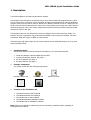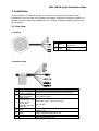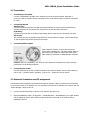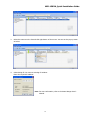
1
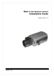
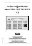
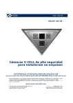
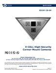
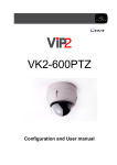
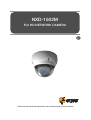
NXD-1502M
Full HD NETWORK CAMERA
GB
Please read this manual thoroughly before use and keep it handy for future reference.
NXD-1502M, Quick Installation Guide
1. Description
This manual applies to the NXD-1502M network camera.
The Network Camera supports the network service for a sensor image with progressive scan, which
can be monitored on a real-time screen regardless of distances and locations. By using its dedicated
program, many users are able to have an access to the Network Camera at once or a single user can
monitor various network cameras at the same time. It also enables users to play, store and retrieve a
monitoring image by using a PC. All the settings and real-time monitoring screens are also provided
through an access to the web.
The Network Camera is fully featured for security surveillance and remote monitoring needs. It is
based on the DSP compression chip, and makes it available on the network as real-time, full frame
rate Motion JPEG and H.264 (or MPEG-4) video streams.
The alarm input and alarm output can be used to connect various third party devices, such as, door
sensors and alarm bells.
•
Installation Steps
Follow these steps to install the Network Transmitter on your local network (LAN):
1.
2.
3.
4.
•
Check the package contents against the list below.
Connect the Network Camera. See page 3.
Set an IP address. See page 4.
Set the password. See page 6.
Package Component
The system comes with the following components:
Network Camera unit
Template Sheet
•
Installation CD
Installation Guide
Accessory Kit
Contents in the installation CD
1.
2.
3.
4.
5.
The
The
The
The
The
Network Camera User’s Manual
NautilusClient16 User’s Manual
Nautilus Server User’s Manual
NautilusClient16 Installation software
Nautilus Server Installation software
Note: Check your package to make sure that you received the complete system, including all
components shown above.
NXD-1502M, Quick Installation Guide
2. Installation
For the operation of the Network Camera, it is necessary to connect a network cable for data
transmission, power connection from supplied power adapter. Depending on operation methods, it is
possible to connect an alarm cable additionally. For its fixation on different locations, please consult
with an installer.
2.1 Over View
• Top View
NO
Name
1
Lens
2
Extension
Cable
Description
Allows wide area to be
monitored
26pin camera extension
cable
• Extension Cable
NO
1
2
3
Wire Color
Red: AC24V/DC12V
White: AC24V/GND
Green: AC24V/DC12V
Black: AC24V/GND
Pink: Alarm In
Yellowish Green: GND
Yellow: AD Key
Brown: GND
Light Blue: Alarm Out
Gray: GND
Description
Main Power, 2pin terminal, DC12V/AC24V 330mA(4.0W)
Heater Power, 2pin terminal, max. 10Watt @ DC12V,
max. 20Watt @ AC24V
Alarm Input, AD Key Input, Alarm Output:
6pin terminal.
Gray
Ethernet, RJ-45 port compatible with 10/100Mbps PoE.
Modular Jack
Video Composite Output, BNC Jack
Audio line output, Stereo Jack
Black
Audio line input, Stereo Jack
4
Black
5
6
7
Black
2
NXD-1502M, Quick Installation Guide
2.2 Connection
•
Connecting to the RJ-45
Connect a standard RJ-45 cable to the network port of the network camera. Generally a
cross-over cable is used for directly connection to PC, while a direct cable is used for connection
to a hub.
•
Connecting Alarms
AI(Alarm In) :
You can use external devices to signal the network camera to react on events. Mechanical or
electrical switches can be wired to the AI (Alarm In) and G (Ground) connectors.
G(Ground) :
Connect the ground side of the alarm input and/or alarm output to the G (Ground) connector.
Alarm Out :
The network camera can activate external devices such as buzzers or lights. Connect the device
to the AO (Alarm Out) and G (Ground) connectors.
•
Connecting Video Output
Video Output is used for an easy zoom and focus
control when installing lens. Set Video Switch (SW2 on
the board) to On position to output the video signal.
Video Output is restricted to VGA(640x480) resolution.
Caution: After lens installation, you must set Video Switch to Off position to provide the best
performance of the Network Camera.
•
Connecting the Power
Connect the power of DC12V or AC24V 330mA for the network camera. Connect the positive(+)
pole to the ‘+’ position and the negative(-) pole to the ‘-‘ position for the DC power.
2.3 Network Connection and IP assignment
The Network Camera supports the operation through the network. When a camera is first connected
to the network it has no IP address. So, it is necessary to allocate an IP address to the device with the
“Smart Manager” utility on the CD.
1.
Connect the Network Camera / device to the network and power up.
2.
Start SmartManager utility ( All programs > NautilusClient16 > SmartManager), the main window
will be displayed, after a short while any network devices connected to the network will be
displayed in the list.
3
NXD-1502M, Quick Installation Guide
3.
Select the camera on the list and click right button of the mouse. You can see the pop-up menu
as below.
4.
Select Assign IP. You cam see a Assign IP window.
Enter the required IP address.
Note: For more information, refer to the Smart Manger User’s
Manual.
4
NXD-1502M, Quick Installation Guide
3. Operation
The Network Camera can be used with Windows operating system and browsers. The recommended
browsers are Internet Explorer, Safari, Firefox, Opera and Google Chrome with Windows.
3.1 Access from a browser
1.
2.
3.
Start a browser (Internet Explorer).
Enter the IP address or host name of the Network Camera in the Location/Address field of your
browser.
You can see a starting page. Click Live View or Setup to enter web page.
4.
The encoder’s Live View page appears in your browser.
3.2. Access from the internet
Access from the internet once connected, the Network Camera is accessible on your local network
(LAN). To access the video encoder from the Internet you must configure your broadband router to
allow incoming data traffic to the video encoder. To do this, enable the NAT-traversal feature, which
will attempt to automatically configure the router to allow access to the video encoder. This is enabled
from Setup > System > Network > NAT.
For more information, please see “3.5.5 System>Network>NAT” of User’s Manual.
5
NXD-1502M, Quick Installation Guide
3.3 Setting the admin password over a secure connection
To gain access to the product, the password for
the default administrator user must be set. This
is done in the “Admin Password” dialog, which is
displayed when the network camera is accessed
for the setup at the first time. Enter your admin
name and password, set by the administrator.
Note: The default administrator username and
password is “admin”. If the password is lost, the
Network Camera must be reset to the factory
default settings. See “3.6 Resetting to the Factory
Default Settings”.
3.4 Live View Page
The live view page comes in eight
screen
modes
like
1920x1080,
1280x1024, 1280x720, 720x480(576),
640x480,
352x240(288),
and
320x240. Users are allowed to select
the most suitable one out of those
modes. Please, adjust the mode in
accordance
with
your
PC
specifications
and
monitoring
purposes.
1)
General controls
Live View Page
Search & Playback Page
Setup Page
Help Page
The video drop-down list allows you to select a customized or pre-programmed
video stream on the live view page. Stream profiles are configured under Setup > Basic
Configuration > Video & Image. . For more information, please see “3.5.1 Basic Configuration >
Video & Image” of User’s Manual.
The resolution drop-down list allows you to select the most suitable one
out of video resolutions to be displayed on live view page.
The protocol drop-down list allows you to select which combination of
protocols and methods to use depends on your viewing requirements, and on the properties of
your network.
6
NXD-1502M, Quick Installation Guide
2)
Control toolbar
The live viewer toolbar is available in the web browser page only. It displays the following
buttons:
The Stop button stops the video stream being played. Pressing the key again toggles the
start and stop. The Start button connects to the network camera or start playing a
video stream.
The Pause button pause the video stream being played.
The Snapshot button takes a snapshot of the current image. The location where the
image is saved can be specified.
The digital zoom activates a zoom-in or zoom-out function for video image on the live
screen.
The Full Screen button causes the video image to fill the entire screen area. No other
windows will be visible. Press the 'Esc' button on the computer keyboard to cancel full
screen view.
The Manual Trigger button activates a pop-up window to manually start or stop the event.
Use this scale to control the volume of the speakers.
Use this scale to control the volume of the microphone.
Use this scale to control the volume of the speakers and microphones.
3)
Video and Audio Streams
The video encoder provides several images and video stream formats. Your requirements and the
properties of your network will determine the type you use.
The Live View page in the video encoder provides access to H.264, MPEG-4 and Motion JPEG
video streams, and to the list of available video streams. Other applications and clients can also
access these video streams/images directly, without going via the Live View page.
7
NXD-1502M, Quick Installation Guide
3.5 Network Camera Setup
This section describes how to configure the network camera, and is intended for product
Administrators, who have unrestricted access to all the Setup tools; and Operators, who have access
to the settings for Basic, Live View, Video & Image, Audio, Event, and System Configuration.
You can configure the network camera by clicking Setup in the top right-hand corner of the Live View
page. Click on this page to access the online help that explains the setup tools
When accessing the Network Camera for the first time,
the “Admin Password” dialog appears. Enter your admin
name and password, set by the administrator.
Note: If the password is lost, the Network Camera must
be reset to the factory default settings.
See “3.6 Resetting to the Factory Default Settings”.
3.6 Resetting to the factory default settings
To reset the Network Camera to the original factory settings, go to the Setup>System >Maintenance
web page (described in “3.5.5 System>Maintenance” of the User’s Manual) or use the control button
on the network camera, as described below:
Follow the instructions below to reset the Network Camera to the factory default settings using the
Reset Button.
1.
2.
3.
4.
5.
Switch off the Network Camera by disconnecting the power adapter.
Press and hold the Control Button with a straightened paperclip while reconnecting the power.
Keep the Control button pressed until the Status and Power indicator blink.
Release the Control Button.
When the Power Indicator changes to Green (may take up to 1 minute), the process is complete
and the network video transmitter has been reset.
6. The transmitter resets to factory defaults and restarts after completing the factory reset.
CAUTION: When performing a Factory Reset, you will lose any settings you have saved.
3.7 More Information
For more information, please see the Network Camera User’s Manual, which is available on the CD
included in this package.
8
eneo® is a registered trademark of Videor E. Hartig GmbH
Exclusive distribution through specialised trade channels only.
Videor E. Hartig GmbH
Carl-Zeiss-Straße 8 • 63322 Rödermark, Germany
Tel. +49 (0) 6074 / 888-0 • Fax +49 (0) 6074 / 888-100
www.videor.com
www.eneo-security.com
Technical changes reserved.
© Copyright by Videor E. Hartig GmbH 10/2011