1
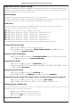
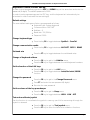
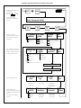
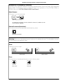
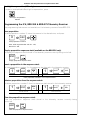
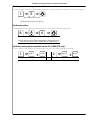
Installation and Setup Instruction
for
Keyboard 1500M, 1501M, 1502M & 1503M
ADPRO
DET
ON
DET
OFF
MODE
1/2
F1
F2
F3
F4
7
8
9
4
5
6
1
2
3
ESC
0
CLR
F5
MENU
F6
F7
INS
AUTO
F8
F9
ON
OFF
F10
F11
DEL
SHIFT
AUX
VCR
1
AUX
VCR
2
?
2821-00037, Rev.170898
HEAD OFFICE: HØRKÆR 24, P.O. BOX 720, DK-2730 HERLEV, DENMARK
TELEPHONE: +45 44 50 33 00, TELEFAX: +45 44 50 33 33
E-MAIL: [email protected], HOME PAGE: www.ernitec.dk
UK OFFICE: ERNITEC UK, GERRARD HOUSE, WORTHING ROAD, EAST PRESTON, WEST SUSSEX BN16 1AW, ENGLAND
TELEPHONE: 01903 77 27 27, TELEFAX: 01903 77 27 07, E-MAIL: [email protected]
FRENCH OFFICE: ERNITEC FRANCE, PARC PEREIRE, 95 RUE PEREIRE, BAT. D, 78100 SAINT GERMAINE EN LAYE, FRANCE
TELEPHONE: (1) 39 21 12 00, TELEFAX: (1) 39 21 12 95, E-MAIL: [email protected]
GERMAN OFFICE: ERNITEC GmbH., STORMARNRING 28, 22145 STAPELFELD, GERMANY
TELEPHONE: (040) 67 56 25 0, TELEFAX: (040) 67 56 25 25, E-MAIL: [email protected]
JAPAN OFFICE: ERNITEC JAPAN LTD., 8-16 GAKUEN-HIGASHIMACHI, 1-CHOME KODAIRA-SHI, TOKYO 187-0043, JAPAN
TELEPHONE: (0)423 46 6290, TELEFAX: (0)423 46 5646, E-MAIL: [email protected]
F12
Installation and Setup instruction for Keyboard Series 1500
Validity
This manual covers the following keyboards:
Keyboard type 1500M, 1501M, 1502M or 1503M software version 1.1 Release
17.08.98 or later.
Compatibility
The Series 1500 keyboards are compatible with the following equipment:
SYSTEM 500M/1000M
1501M/1503M: Software Version 4.1 Release 10.03.97, or later.
1502M: Any version; however the Adpro functions are available only when
supported by the matrix software.
1500M: Any version.
Series BDR-510 telemetry receiver, software V.1.0 Release 05.11.96, or later.
Series BDR-550 telemetry receiver, software V.2.0 Release 16.10.96, or later.
BDR-575 telemetry receiver, software version 1.0 Release 13.03.97, or later.
Integrated Camera Unit (ICU), software version 1.0.
Approvals
All keyboard types are CE certified and approved with respect to EN 50081-1 and EN 50130-4
(EMC) and EN 60950 (LVD).
Introduction
The keyboards Series 1500 can be used for operating SYSTEM 500M and SYSTEM 1000M as
well as for direct operation of telemetry receivers Series BDR-510, Series BDR-550, BDR-575
and Integrated Camera Units (ICU).
However, variable speed operation of BDR-575 and the ICU is only possible when used with
keyboard 1501M or 1503M.
Keyboard types
Keyboard 1500M is equipped with a serial port with selectable RS-232/RS-485
interface.
Keyboard 1501M is furthermore equipped with a joystick for variable speed
operation of BDR-575 and the ICU.
Keyboard 1502M is equipped with a serial port with selectable RS-232/RS-485
interface and an ARC-net port for connection to SYSTEM 500M and 1000M. A
LCD display with two lines of each 40 characters and back light illumination are
used as status display and for user messages. The keyboard features Site selection
and Macro functions and is able to control the Adpro integration features in
connexion with SYSTEM 1000M, and SYSTEM 500M. For further information on
these subjects, refer to the SYSTEM 500M/1000M User- and Programming
Manuals.
Keyboard 1503M is furthermore equipped with a joystick for variable speed
operation of BDR-575 and the ICU.
Unpacking the keyboard
After unpacking the keyboard, carefully check for any sign of damage. Any such damage
should be reported to your supplier, or to Ernitec A/S directly, before installation.
Check that the keyboard packing carton contains the following items:
1 Keyboard 1500M, 1501M, 1502M or 1503M.
1 Keyboard Installation Manual (this manual)
1 Connector kit
1 Power supply
Page 2
Installation and Setup instruction for Keyboard Series 1500
Keyboard connections
The keyboard connections are shown on figure 1.
#
Description
1500M/1501M
1-10
1502M/1503M
Power supply connector for the supplied mains adaptor or for external voltage 9-18 VAC/VDC 2,7 VA
1-11
N/A
ARC-net connector used for interconnection of
SYSTEM 1000M units and keyboards.
1-12
N/A
Switch for ARC-net line termination.
1-13
RS-485/RS-232 connector used for connection of SYSTEM 500M/1000M, alarm printer or direct
connection to Series BDR-500 or ICU's.
1-14
Switch for RS-485 line termination.
Installation
When the installation is completed make sure to set up the keyboard in accordance with the
installation and the intended use; refer to the Set-up section.
Power connection
Connect the power supply unit to the keyboard PSU connector 1-10 (refer to figure 1) and to
the mains socket.
ARC-net connection to SYSTEM 1000M
Connect the ARC-net cable to socket 1-11 (refer to figure 1):
SYSTEM 1000M
Pin
Description
Keyboard 1502M/1503M
Pin
Description
1 or 5 Positive signal
1 or 5 Positive signal
6 or 9 Negative signal
6 or 9 Negative signal
All SYSTEM 1000M units are interconnected through the ARC-net. Also the keyboards might
be connected to the ARC-net. Remember to terminate the ARC-net line in both ends of the
cable. This is done by setting the belonging small switches to the 120 Ω or 100 Ω position
corresponding to the characteristic impedance of the cable used, refer to fig. 1-12. Make sure,
that only the first and the last physical unit on the cable is terminated, refer to figure 2 for
termination instructions. On all other units the termination switches should be set to the OFF
position.
Maximum cable length is approximately 1700 metres.
Note: The ARC-net is a Local Area Network, and is as such very dependant on a good quality
cable installation. It is therefore important to use high quality twisted pair data transmission
cable, with a characteristic impedance of 120 Ω or 100 Ω.
Warning: Do not in any way connect an optional cable shield/screen!
Recommended 120 Ω types are:
Belden 8132 (2 pairs).
Alcatel 6806 Ecomatch (4 pairs).
For further information on suitable cables for ARC-net, refer to the SYSTEM 1000M Installation
Instruction.
Page 3
Installation and Setup instruction for Keyboard Series 1500
RS-485 connection to SYSTEM 500M/1000M
Connect the RS-485 cable to socket 1-13 (refer to figure 1):
SYSTEM 500M/1000M
Pin
Keyboard 580M/1801M/1802M
Description
Pin
Description
6 or 8 Positive signal
6 or 8 Positive signal
7 or 9 Negative signal
7 or 9 Negative signal
1, 4 or 5* GND (Connect to cable screen)
1, 4 or 5* GND (Connect to cable screen)
Remember to terminate the RS-485 line in both ends of the cable. This is done by setting the
belonging small switches to the 120 Ω or 100 Ω position corresponding to the characteristic
impedance of the cable used, refer to fig. 1-14. Make sure, that only the first and the last
physical unit on the cable is terminated, refer to figure 2 for termination instructions. On all
other units the termination switches should be set to the OFF position.
Maximum cable length is 1200 metres.
It is recommended to use high quality twisted pair cable designed for data transmission.
*Connection of cable shield/screen is optional and will normally not be needed.
RS-485 connection to telemetry receivers Series BDR-500, the ICU and BED-108
Connect the RS-485 cable to socket 1-13 (refer to figure 1):
Series 1500
Pin
Desc.
BDR-550/1
Pin
Desc.
BDR-510/4
Pin
6 or 8 Pos.
*X5- PCM IN-
7 or 9 Neg.
*X5+ PCM IN+ X7-
1, 4, 5 GND
Desc.
BDR-511/2/3
Pin
Desc.
X7+ CTRL IN+ X12+ PCM IN+
CTRL IN-
X12-
PCM IN-
BDR-575
ICU
Pin
Desc.
BED-108
Pin
Desc.
Pin
Desc.
2
N/A
1
COM+ X3+ ERNA+
1
N/A
2
COM-
X3- ERNA-
Do NOT connect!
Details on interconnecting various types of telemetry receivers and termination of the RS-485
line can be found on figure 3.
Telemetry Receivers Series BDR-51X and BDR-55X and the BED-108 Control Signal Distributor
Unit will terminate the RS-485 properly by themselves when installed in the correct daisy chain
configuration and do not require additional line termination. The ICU and the BDR-575 are
bus-connected and consequently the line must be terminated, on the ICU with an external
resistor, on the BDR-575 by enabling the RS-485 LK1 jumper on the interface board.
Different types of telemetry receivers can also be mixed on the common control line.
Remember, that each telemetry receiver/ICU must have an unique address equal to the camera
number minus 1, refer to the relevant telemetry receiver manual. Also the Series 1500
keyboard must be set for direct control of telemetry receivers (CamCrtl), refer to the Set-up
section located later in this manual.
Maximum cable length is 1200 metres. However, telemetry receivers Series BDR-51X and
BDR-55X as well as the BED-108 features an active control signal repeater allowing further
3000 meters (BDR-51X further 1200 meters) distance to the next unit.
Page 4
Installation and Setup instruction for Keyboard Series 1500
RS-232-C connection to SYSTEM 500M/1000M
Connect the RS-232-C cable to socket 1-13 (refer to figure 1).
SYSTEM 500M/1000M
Pin
Description
Keyboard Series 1500
Pin
Description
3 Transmit
2 Receive
2 Receive
3 Transmit
1, 4 or 5 Ground (To cable screen also)
1, 4 or 5 Ground (To cable screen also)
Maximum cable length is 50 metres.
The RS-232 port on the 1502M or 1503M keyboard can also be used for connection to a serial
printer for alarm logging, if the keyboard is connected to the SYSTEM 1000M via the ARC-net.
To use the feature the SYSTEM 1000M must be set-up accordingly, refer to the SYSTEM
1000M Programming Manual.
Also telemetry receivers can be controlled via the RS-232 port. The Transmit signal should be
connected to the positive terminal on the telemetry receiver and the GND signal to the
negative terminal, except on the Series BDR-550 where the signals must be reversed.
Keyboard Set-up
When using external keyboard(s) in an matrix installation, it is important to check the factory
programmed default settings for the keyboards before use to avoid conflict or dead-lock
situations like several keyboards having the same address.
When used as a matrix keyboard, make sure the following parameters are set correct:
Keyboard type=SysKbd / System keyboard.
Communication media: In accordance with the interface used.
Baud rate: In accordance with baud rate set in SYSTEM 500M/1000M.
Keyboard address: Make sure the address set is unique.
When used for direct control of telemetry receivers/ICU's:
Keyboard type=CamCrtl / Direct camera control.
Communication media=RS-485.
Beeper
During set-up mode the key-beep sound is changed to indicate you are in set-up.
Various different beeps indicates valid or invalid selections.
Keyboards 1500M and 1501M will indicate wrong entries during set-up by no key-beep at all
and will await a valid selection - set-up is not left until a valid selection has been made.
Operation of AUX relays
Set-up allow three different operation methods:
Latched, or toggled function.
Un-latched, or momentary, push-button, function.
1801M emulation, must be selected when the keyboard is connected to SYSTEM
500M/1000M software version 2.1 or lower.
Might also be selected when used with newer matrix software; in this case is the
functionality of the AUX-relays, latched or un-latched, controlled by the matrix
set-up individually for each camera.
Page 5
Installation and Setup instruction for Keyboard Series 1500
Keyboard 1500M/1501M Setup
If several parameters should be changed it is necessary to start from the beginning with each
parameter, by pressing the ESC and MENU keys at the same time, and entering the password.
The default password is 0000 (four times zero).
Default settings
The default settings are indicated with an '*' on the next page.
Each time a setting is changed, the keyboard is automatically re-booted in order to activate the
new setting. Invalid entries are not accepted, indicated by no key-beep.
Quick set-up
The basic settings of the keyboards 1500M/1501M can easily be set up, by pressing the
following keys during power ON of the keyboard:
ESC + 0: Direct Camera Control - RS485 - 2400 baud
ESC + 2: System Keyboard - RS232 - 19200 baud - Keyboard no. 2/3
ESC + 3: System Keyboard - RS485 - 19200 baud - Keyboard no. 3
ESC + 4: System Keyboard - RS485 - 19200 baud - Keyboard no. 4
ESC + 5: System Keyboard - RS485 - 19200 baud - Keyboard no. 5
ESC + 6: System Keyboard - RS485 - 19200 baud - Keyboard no. 6
The remaining settings are not affected by the above quick set-up procedure.
Change the keyboard type
Press the key 1 to change the keyboard type.
Press 1 to set the keyboard for Direct Camera Control, press 2 to set the
keyboard for System Control.
Change of keyboard address
Press the key 2 to change the keyboard address, press a number between 3
and 6 indicating the new keyboard address.
Change the baud rate
Press the key 3 to change the baud rate setting.
Press the key 1 for 1200 baud, 2 for 2400, 3 for 4800, 4 for 9600, 5 for 19200 or
6 for 38400 baud rate.
Change the interface type
Press the key 4 to change the interface type.
Press 1 to set RS-232 interface, press 2 to set RS-485 interface.
Change the function of the AUX relays (refer to the AUX relays section on page 5)
Press the key 5 to change the function of the AUX relays.
Press 1 for latched function, 2 for un-latched, 3 for 1801M mode.
Calibrate joystick (1501M only)
This is a service function. Use this function to re-calibrate the joystick in case e.g. pan & tilts are
moving although the joystick is released.
Press the key 7 to activate the function
Release the joystick, including the focus!
Press the CLR key to calibrate the joystick.
Change the password
Page 6
Installation and Setup instruction for Keyboard Series 1500
Press the key 9 to change the password, and enter the new password (4 digits). Re-enter the
new password.
Page 7
Installation and Setup instruction for Keyboard Series 1500
Start programming of
keyboard.
ESC
MENU
Enter Password
(Default password is
0000).
0
0
Set keyboard mode of
operation
1
1
Direct Camera control
2
System keyboard *
3
Keyboard No. 3
4
Keyboard No. 4 *
5
Keyboard No. 5
6
Keyboard No. 6
1
1200 Baud
2
2400 Baud
3
4800 Baud
4
9600 Baud
5
19200 Baud *
6
38400 Baud
1
RS232
2
RS485 *
1
Aux latch *
2
Aux Nolatch
3
Aux 1801M
1
Beep OFF
2
Beep HIGH *
3
Beep LOW
Set address.
Set Baud rate.
Set interface type.
Set function of AUX
relays.
Set volume of beeper.
2
3
4
5
6
Re-calibrate joystick.
7
Change password.
Enter new password.
9
Re-enter new password.
Setup is finished
Page 8
+
ESC
0
CLR
0
Joystick calibrated
1
2
3
4
1
2
3
4
*Default factory settings
Installation and Setup instruction for Keyboard Series 1500
Keyboard 1502M/1503M Set-up
In order to start programming press the ESC and MENU keys at the same time and enter the
password (4 digits). The default password is 0000.
In order to exit programming press the ESC key, and the keyboard will automatically be
re-booted in order to activate the new setting(s).
Default settings
The main default settings are factory programmed as follows:
Keyboard type: System keyboard
Communication: ARC NET
Address : 4
Baud rate: 312,50 Kbs
Password: 0000
Change keyboard type
Press the key F4 to toggle between SysKbd or CamCrtl.
Change communication media
Press the key F6 to toggle between ARC NET - RS232 - RS485
Set baud rate
Press the F7 key to toggle between the valid baud rates.
Change of keyboard address
Press the F9 key to get to the Kdb.No menu.
Press the F4 key to toggle between the valid keyboard numbers.
Set the function of the AUX keys
Press the F9 key to get to the AUX menu.
Press the F6 key to toggle between Latch/No Latch/1801M
function.
Change the password
Press the F9 key to get to the Change Password menu.
Press F7 and enter the new password (4 digits).
Re-enter the new password.
Set the volume of the key-press beeper
Press the F9 key to get the Beep menu.
Press the F4 key to toggle between HIGH - LOW - OFF.
Test and re-calibrate joystick
Use this function to re-calibrate the joystick in case e.g. pan & tilts are moving although the
joystick is released.
Press the F9 key to get the Test joystick menu.
Press the F7 key to enter the test and re-calibation functions.
Page 9
Installation and Setup instruction for Keyboard Series 1500
Start programming of
keyboard.
Press ESC to leave
OK
set-up.
Enter Password
(Default password is
0000)
ESC
+
Enter Password: XXXX
0
Select Mode of
operation, Baud rate
and communication
interface.
Set keyboard address.
Set Function of AUX
relays in BDR-5XX/ICU
Change password.
FAULT
MENU
0
0
F4:OpMode F6:Comm.
XXXXXX
XXXX
CamCtrl
SysKbd*
(RS232 only)
F7:Baud
XXXX
F9:
More
RS232
1200/2400/4800
RS485
ArcNet*
9600/19200/38400
156.25
312.5*
F4:Kbd. No F6: AUX
X
XX XXXX
Kbd. 2
Kbd. 3
0
F7:Change
Password
F9:
More
Latch*
No Latch
1801M
Kbd. 4 *
Kbd. 6
Kbd. 10 (7-10 ARCnet only)
Enter Password: XXXX
Reenter Password: XXXX
Service menu only
Set beeper tone.
Reset keyboard settings
to default (marked with
an *).
Test and re-calibrate
joystick.
Page 10
F4: ArcNet
Stat.
F6:Error
Log
Displays
ARCnet
statistics.
Displays
error log.
F4: Beep
XXXX
F6:Reset
Settings
HIGH*
LOW
OFF
Resets all
settings to
default
F7:S/W
Ver.
F9:
More
Displays
software
version &
release date.
F7:Test
Joystick
Test and recalibration
of joystick
F9:
More
Installation and Setup instruction for Keyboard Series 1500
Operation of telemetry receivers
This section will describe operation telemetry receivers diretly from the Series 1500 keyboard
when mode of operation is set to Camera Control. For operation of the SYSTEM 500M or
1000M, refer to the SYSTEM 500M/1000M User Manual.
Select Camera
If Camera 3 is to be controlled:
3 ð
Select camera number 3
All subsequent operations are now directed to camera 3 (=address 2) until
a new camera is selected.
Select all cameras (broadcast)
If all cameras should be operated simulteneously, press:
Broadcast commands
Warning: When e.g. activating the pan functions all cameras will pan! The broadcast function
should therefore be used with care!
Zoom
Change the focal length:
1500M/1502M
1501M/1503M
1500M/1502M
Zoom wide
1501M/1503M
Zoom narrow
Focus
If the picture on the selected monitor is not in focus, press:
Focus near
Focus far
Page 11
Installation and Setup instruction for Keyboard Series 1500
Iris
If the picture on the monitor is too dark or light, press:
Iris open
Iris close
Note: Available only if supported by the connected equipment.
Pan Camera
If the camera should be panned left or right, press:
1500M/1502M
1501M/1503M
1500M/1502M
Pan left
1501M/1503M
Pan right
JOYSTICK NOTE: When controlling a variable speed Pan/tilt, BDR-575 or ICU, pushing the
joystick towards its extremes will increase speed.
Tilt Camera
If the camera should be tilted up or down, press:
1500M/1502M
1501M/1503M
1500M/1502M
Tilt up
1501M/1503M
Tilt down
JOYSTICK NOTE: When controlling a variable speed Pan/tilt, BDR-575 or ICU, pushing the
joystick towards its extremes will increase speed.
Activating an AUX-relay
To activate AUX-relay 2, press:
2 ð
AUX
Activate AUX 2 relay.
Note: If the Keyboard 1500 is set for No Latch operation the relay is
automatically de-activated when the AUX-key is released. If set for Latch
operation the relay will remain activated when the key is released.
De-activating an AUX-relay
To de-activate AUX-relay 2, press:
2 ð
AUX
De-activate AUX 2 relay.
Note: Used only if the Keyboard 1500 is set for Latch operation.
Page 12
Installation and Setup instruction for Keyboard Series 1500
Auto panning (BDR-575 and ICU only)
To start auto panning, press:
AUTO
ð
Start auto panning
Call Preposition (not available on Series BDR-51X)
To call preposition number 3, press:
3 ð
Call preposition number 3
Note: Valid range BDR-55X and ICU: 1-30, BDR-575: 1-126.
Start Sequence of pre-positions
To start the pre-programmed sequence of pre-positions, press:
Start sequence.
The sequence of pre-positions is automatically aborted when
another function is operated.
Remove/insert text (Series BDR-550 only)
Remove/insert the text generated by the currently controlled telemetry receiver:
?
150XM
Remove or Insert text from
telemetry receiver
Auto focus (ICU only)
In order to switch to auto focus, press:
AUTO
ð
or
AUTO
ð
AUTO
ð
Enable auto focus
Auto iris (ICU only)
In order to switch to auto iris, press:
AUTO
ð
or
Enable auto iris
Page 13
Installation and Setup instruction for Keyboard Series 1500
Back light compensation (ICU only)
In order to enable/disable Back light compensation, press:
Back light compensation
ON/OFF
Programming the ICU, BDR-55X & BDR-575 Telemetry Receiver
The programming features are not available on the telemetry receivers Series BDR-51X.
Save preposition
To save preposition number 3, move the camera to the desired view, and press:
3 ð
ESC
ð
Save preposition number 3
Note: Valid range BDR-55X and ICU: 1-30,
BDR-575: 1-126.
Display preposition sequence stack (available on the BDR-55X only)
To display the sequence stack stored in the telemetry receiver currently being controlled:
ESC
ð
AUX
Display preposition sequence stack
Insert a preposition in the sequence stack
To insert preposition number 1 in the sequence stack stored in the telemetry receiver:
1 ð
ESC
ð
VCR
1
1500M/1502M
1 ð
SHIFT
+
INS
1501M/1503M
Insert preposition number 1 in the sequence stack
Delete a preposition from the sequence stack
To delete preposition number 1 from the sequence stack stored in the telemetry receiver:
1 ð
ESC
ð
VCR
2
1500M/1502M
1 ð
SHIFT
+
DEL
1501M/1503M
Delete preposition number 1 from the sequence stack
Clear the preposition sequence stack
Clear the preposition sequence stack stored in the telemetry receiver currently being
controlled:
ESC
ð
AUX
Clear the preposition sequence stack
Page 14
Installation and Setup instruction for Keyboard Series 1500
Set the pre-position sequence dwell time
To set the dwell time for the telemetry receiver currently being controlled to 15 seconds, press:
1 ð 5 ð
Set dwell time to 15 sec.
The dwell time range is 0 to 255 sec.
Set Home position
To use preposition 8 as Home-position with a time-out of 60 seconds, press:
8 ð
ð 6 ð
Use pre-position 8 as Homeposition with a 60 sec. time-out
Note, that the time-out entry automatically is multiplied with 10.
Max. time-out entry is 255 corresponding to 2550 seconds.
Set Auto panning limits (available on the ICU & BDR-575 only)
To set the two limit positions for auto panning, for the camera being controlled:
1 ð
SHIFT
+
AUTO
2 ð
SHIFT
+
1501M/1503M only
1501M/1503M only
Set auto panning limit 1
Set auto panning limit 2
AUTO
Page 15