1
AIRCRAFT
RECEIVER KIT
Ramsey Electronics Model No.
AR2
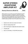
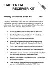
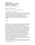
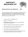
A new and improved version of our popular Aircraft Receiver kit,
this new model features an LCD display, scan function, and
increased sensitivity, all in a rugged metal enclosure. Rivals
professional units costing much more and you have bragging
rights because you built it yourself!
•
Tunes the entire 118 - 136 MHz Air band
•
Operates on 12 to 15 VDC
•
Scan function “finds” the signals for you; no more laborious
tuning to find a transmission
•
Memory locations make it easy to refind your local favorites
•
Listen to control towers, centers, and planes en-route
•
Very sensitive; picks up planes 100 miles away!
•
Great project for all pilots and flight students
•
Clear, concise step-by-step instructions carefully guide you to a
finished kit that not only works - but you’ll learn too!
AR2 • 1
PARTIAL LIST OF AVAILABLE KITS:
RAMSEY TRANSMITTER KITS
• FM10A, FM25B, FM30, FM Stereo Transmitters
• FM100B, FM35 Professional FM Stereo Transmitters
• AM1, AM25 AM Broadcast Band Transmitters
RAMSEY RECEIVER KITS
• FR1 FM Broadcast Receiver
• AR1 Aircraft Band Receiver
• SR2 Shortwave Receiver
• AA7 Active Antenna
• SC1 Shortwave Converter
RAMSEY HOBBY KITS
• SG7 Personal Speed Radar
• SS70C Speech Scrambler/Descrambler
• TT1 Telephone Recorder
• SP1 Speakerphone
• MD3 Microwave Motion Detector
• PH14 Peak hold Meter
• LC1 Inductance-Capacitance Meter
RAMSEY AMATEUR RADIO KITS
• HR Series HF All Mode Receivers
• DDF1 Doppler Direction Finder Kit
• QRP Series HF CW Transmitters
• CW7 CW Keyer
• QRP Power Amplifiers
RAMSEY MINI-KITS
Many other kits are available for hobby, school, scouts and just plain FUN. New
kits are always under development. Write or call for our free Ramsey catalog.
AR2
Ramsey Electronics publication No. AR2 Rev. 1.3a
July 2005
COPYRIGHT ©2004 by Ramsey Electronics, Inc. 590 Fishers Station Drive, Victor, New York
14564. All rights reserved. No portion of this publication may be copied or duplicated without the
written permission of Ramsey Electronics, Inc. Printed in the United States of America.
AR2 • 2
Ramsey Publication No. AR2
Manual Price Only $5.00
INSTRUCTION MANUAL FOR
AIRCRAFT RECEIVER
TABLE OF CONTENTS
Introduction .......................................... 4
What You Can Expect to Hear ............ 4
Circuit Description................................ 8
Block Diagram ................................... 11
AR2 Parts List.................................... 14
Assembly Instructions........................ 16
AR2 Schematic Centerfold ................ 18
Antenna Considerations .................... 29
Setup and Testing.............................. 29
Troubleshooting ................................. 34
Warranty ............................................ 35
RAMSEY ELECTRONICS, INC.
590 Fishers Station Drive
Victor, New York 14564
Phone (585) 924-4560
Fax (585) 924-4555
www.ramseykits.com
AR2 • 3
INTRODUCTION TO THE AR2 AVIATION RECEIVER KIT
The Ramsey AR2 Aviation Receiver is a new design of our original Ramsey
AR1 Aircraft Receiver. The AR1 has been built and loved for years by
hobbyists with an interest in both aviation and electronics. The AR2 design
takes the best of the AR1 and adds scanning functions, and a slick metal case
for superior noise reduction. It is characterized by exceptional sensitivity,
image rejection, signal-to-noise ratio and stability. It is designed for casual
"listening in"- on both ground and air communication, for both commercial
airlines and general aviation. The AR2 has been built by folks of all ages and
skill levels, and in less time than it takes to fly solo!
118-136 MHz, WHAT YOU CAN EXPECT TO HEAR
A basic fact about the VHF Aviation Band which even licensed pilots can
overlook or forget is that communications are in the AM mode, not FM, as in
the case of the FM broadcast band immediately below it, and the VHF public
service and ham bands immediately above it.
No matter where you live you will be able to receive at least the airborne side
of many air traffic communications. You'll hear any aircraft you can see, PLUS
planes up to 100 miles away and more, since VHF signals travel "line of
sight." An airliner at 35,000 feet altitude is still line of sight to your antenna.
Similarly, whatever ground stations you may hear are also determined by this
"line of sight" characteristic of VHF communication. If there are no major
obstacles between your antenna and an airport (tall buildings, hills, etc.) you'll
be able to hear both sides of many kinds of aviation communication. Be
prepared for them to be fast and to the point, and for the same airplane to
move to several different frequencies in the span of a few minutes! Here's a
brief listing of the most common types of services in the NAS (National
Airspace System) with which pilots communicate:
Clearance Delivery
At most metropolitan airports a pilot communicates with the FAA on a
frequency called "Clearance Delivery" to obtain approval or clearance of the
intended flight plan. This communication is done before contacting ground
control for taxi instructions.
Ground Control
From the control tower, ground movements on ramps and taxiways are
handled on the “Ground Control” frequency.
Control Tower
Runway and in-flight maneuvers near the airport, usually within three miles
(takeoffs, local traffic patterns, final approaches and landings) are on the
“Control Tower” frequency.
AR2 • 4
ATIS – Automated Terminal Information System
ATIS, is a repeated broadcast about basic weather information, runways in
use, and any special information such as closed taxiways or runways.
ASOS/AWOS – Automated Surface Observing System/Automated Weather
Observing System
This system is similar to ATIS but usually located at un-towered airports.
Approach Control & Departure Control
These air traffic radar controllers coordinate all flight operations in the vicinity
of busy metropolitan airport areas.
ARTCC – Air Route Traffic Control Center
When you hear a pilot talking with "Jacksonville Center" or "Indianapolis
Center", you know the aircraft is really enroute on a flight rather than just
leaving or just approaching a destination. A pilot will be in touch with several
different "Regional Centers" during a cross-country flight.
CTAF – Common Traffic Advisory Frequency
Airports without control towers are controlled by the pilots themselves and
they rely on the local CTAF frequency dedicated only to advisory
communications between pilots and ground personnel such as fuel service
operators. The people on the ground can advise the pilot on the status of
incoming or outgoing aircraft, but the pilot remains responsible for landing and
takeoff decisions. Typical CTAF frequencies are 122.7, 122.8 and 123.0 MHz.
Unicom frequencies are used at manned towered airports for day to day
businesses at 122.75, 122.85, and 122.95 MHz.
FSS - FAA Flight Service Stations
The FAA's network of Flight Service Stations keeps track of flight plans and
provides weather briefings and other services to pilots. Some advisory radio
communication takes place between pilots and a regional "FSS". If there is an
FSS in your local area, but no airport control towers, the FSS radio frequency
will stay interesting. Typical frequencies are 122.1, 122.6, and 123.6 MHz.
Pilots always address the FSS by calling the FSS name followed by “Radio”.
ELT – Emergency Locator Transmitters
Emergency and guard channels are used by airplanes in flight operations
during an emergency or talking on official business and can be heard on
121.5MHz.
ACARS - Aircraft Communication Addressing and Reporting System
ACARS is a digital VHF radio data link which allows airline flight operations
departments to communicate with the various aircraft in their fleet. ACARS is
used by many civilian and business aircraft and is similar to “email for
airplanes". Each aircraft has its own unique address in the system. Traffic is
AR2 • 5
routed via computers to the proper company, relieving some of the necessity
for routine voice communication. With ACARS, routine items such as
departure reports, arrival reports, passenger loads, fuel data, engine
performance data, and more can be retrieved from the aircraft at automatic
intervals. The transmission will sound like a short data burst to the ABM1 user.
THOSE FAST-TALKING PILOTS AND CONTROLLERS!
Aviation communication is brief but it is clear and full of meaning. Usually,
pilots repeat back exactly what they hear from a controller so that both know
that the message or instructions were correctly interpreted. If you are listening
in it is hard to track everything said from a cockpit, particularly in big city
areas. Just to taxi, take off, and fly a few miles, a pilot may talk with 6 or 8
different air traffic control operations, all on different frequencies, all within a
few minutes! Here are the meanings of a few typical communications:
"Miami Center, Delta 545 Heavy out of three-zero for two-five."
Delta Flight 545 acknowledges Miami Center's clearance to descend from
30,000 feet to 25,000 feet altitude. The word "heavy" means that the plane is
a jumbo jet such as 747, DC-10, etc.
"Seneca 432 Lima cleared to outer marker. Contact Tower 118.7."
The local Approach Control is saying that the Piper Seneca with the N-number
(tail number) ending in "432L" is cleared to continue flying an instrument
approach to the outer marker (a precision radio beacon located near the
airport) and should immediately call the airport radio control tower at 118.7
Mhz. This message also implies that the approach controller does not expect
to talk again with that aircraft.
"Cessna 723, squawk 6750, climb and maintain five thousand."
A controller is telling the Cessna pilot to set the airplane's radar transponder to
code 6750, climb to and fly level at an altitude of 5000 feet.
"United 330, traffic at 9 o'clock, 4 miles, altitude unknown."
The controller alerts United Airlines flight #330 of radar contact with some
other aircraft off to the pilot's left at a 9 o'clock position. Since the unknown
plane's altitude is also unknown, both controller and pilot realize that it is a
smaller private plane not equipped with altitude-reporting equipment.
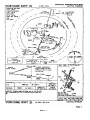
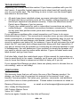
ELECTRONICS & FLYING: DOING IT "BY THE NUMBERS"
A peek at the sample FAA "instrument approach" chart for medium-large
airports shows that pilots deal with many vitally important numbers and must
do so quickly. Among the numbers on that chart, can you find the air-ground
communications frequencies which can be heard on the ABM1 receiver? Can
you find frequencies for uses other than communications?
AR2 • 6
AR2 • 7
CIRCUIT DESCRIPTION
Radio Basics:
We’ll take the circuit section by section; the letters show which part of the
block diagram we’re explaining in each section.
The AR2 is a simple super-heterodyne receiver. A heterodyne receiver is a
receiver that first converts the desired received frequency into an IF
frequency, or Intermediate Frequency. Many radios are designed this way due
to a variety of reasons, but primarily because it is easy to perform filtering and
amplification on the IF signal rather than the RF signal because the IF is a
single frequency or small band of frequencies, whereas RF is quite a bit wider
and usually much higher in frequency than IF.
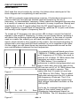
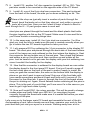
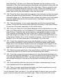
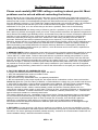
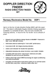
To create an IF frequency we use a mixer (D) to down-convert the band of
interest to the single IF frequency. A mixer is a non-linear device, meaning it
will distort the incoming signal with an applied signal. In the case of a mixer
used on a radio this means you will have two different frequencies on the
inputs, which results in four signals on the output. The received frequency is
connected to one input and the local oscillator or LO is supplied to the other.
On the output you will have these two important frequencies as well as the
sum and difference between the two frequencies.
IF
Fr
LO
Fi
F
Figure 1
IF
Fr
F
Figure 2
LO
Fi
For example the aircraft band goes from
118MHz to 139MHz, and we plan to use
an IF frequency of 10.7MHz, we need to
have an LO of either 10.7MHz above the
frequency we wish to receive, or
10.7MHz below. It is a matter of
preference in which mixing byproduct you
Sum wish to work with, but in the case of the
AR2 we use an LO of 10.7MHz above the
frequency we wish to receive. This
means that the LO needs to tune from
128.7MHz to 149.7MHz. This is called
high-side mixing since the LO is above
the frequency of interest. The LO is
generated using a phase locked loop
and voltage controlled oscillator on the
AR2 (J, D).
Let’s say for example that we wish to
Sum listen to the control tower at ROC
(Rochester International Airport) at
118.300MHz. The LO frequency would
AR2 • 8
have to be set at 118.300 MHz + 10.700 MHz or 129.000MHz. It would then
be sent to the mixer and on the output there would be 129.000MHz (LO),
118.3MHz(Fr), 247.3MHz(Sum) and 10.700MHz (IF). (See Figure 1)
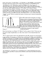
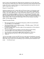
After the mixer we use a narrow-band filter (E) to reject everything but the
10.7MHz IF signal output from the mixer. This works well because 10.7MHz is
far from the next highest frequency, 118.3MHz, so it’s easy to reject
everything but the signal of interest. However, there is another signal you can
receive that is 10.7MHz above the LO frequency. This is called the image
frequency, and can be a real hassle in radio designs. In this case we could
receive not only 118.3MHz but also 139.7MHz (2x IF + Fr). In this case this
“image” is only 700kHz outside the band of interest and is almost impossible
to filter out.
IF
Fr LO
F
Figure 3
Fi
The AR2 reduces the reception of image
frequencies by using good band-pass filters
on the input to reject the image frequencies
before they make it to the mixer (A, C).
Figure 3 to the left shows what the RF input
to the mixer looks like. Notice the Fi is
greatly reduced by the input band pass
Sum filter, but not completely eliminated. The
band pass filter certainly helps and gets rid
of all but the strongest image signals
outside the band.
Now that we have our filtered 10.7MHz IF at the output of the IF filter we can
do some simple amplification on it (F), then send it to be demodulated into
audio.
The IF signal is then sent to the AM detector part (G), where it is mixed down
to yet another IF frequency of 450kHz by combining 10.7MHz with 10.25MHz.
450kHz is used due to the large array of components available at 450kHz, and
it is also the frequency at which our particular AM demodulator works best.
The signal is then amplified greatly to a consistent level using “slow” AGC
within the detector part. The detector is able to receive quality AM signals in a
90dB range, since the AGC can amplify the signal up 90dB. The AGC is
important in that all received signals within its range will be of the same audio
amplitude. Otherwise weak signals would be very quiet, and nearby ones
would be very loud. The reason it is “slow” is to allow changes in level due to
audio to be left alone, but longer-term signal level changes due to distant
signals and close signals to be compensated for.
The 450kHz IF, now that it is a consistent level, is demodulated using a fullwave rectifier and filter to remove the 450kHz, and leave the AM level behind
as shown.
AR2 • 9
AM + 450kHz
Detector +
Audio Out
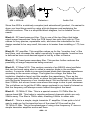
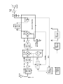
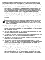
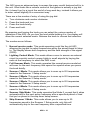
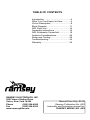
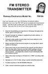
Since the AR2 is a relatively complex (and educational!) product, it’s easiest to
show you how things work by using a block diagram and explaining the
different sections. This is a simplified block diagram, but is suitable for our
needs.
Block A. RF band pass pre-filter. This is one of the two filters that helps
reject image frequencies. Note the PCB layout has coils built right in! This
makes for very precise, repeatable coils, and since the inductance for this
design needed to be very small, this was a lot easier than installing a 1 ½ turn
coil.
Block B. RF amplifier. This amplifier makes up for the “insertion loss” of the
two filters, and increases the radio’s sensitivity to weak signals. Insertion loss
is defined as how much desired signal is lost by a filter or device.
Block C. RF band pass secondary filter. This section further reduces the
possibility of image frequencies being received.
Block D. IF Mixer/VCO. This section consists of an NE602 mixer/oscillator
that can be tuned using what is called a varactor diode in the oscillator
section. A varactor diode is a reverse-biased diode that changes capacitance
according to the reverse voltage. The higher the voltage, the wider the
insulation (depletion layer) and the smaller the capacitance. Thus as the
voltage goes up across the diode, so does the frequency! The tuned inductor
sets the center frequency of our tunable band. We are limited to a little more
than 21MHz, but we are never sure where this range is due to part variances.
The coil allows us to get the 21MHz range centered in our band of interest so
that the frequency will always remain locked throughout the band.
Block E. 10.7MHz IF filter. This is a special ceramic 10.7MHz filter for
narrow-band AM. This helps in rejecting adjacent channels which are only
25kHz away. The filter is 13kHz wide, meaning 6.5kHz to either side.
Block F. This is a simple, single transistor IF amplifier. It has quite a lot of
gain to make up for the insertion loss of the mixer/VCO as well as the
10.7MHz IF filter. This is the advantage of using a low frequency IF since a
simple transistor amplifier works well here.
AR2 • 10
Display
/Control
Microcontroller
K
A
118-139MHz
Antenna
AR2 • 11
L
J
PLL
B
RF Amp
C
RSSI
10.25MHz
Vtune
118-139MHz
VCO
IF1 Mixer
D
12V
F
IF AMP
10.25MHz
Reference
12V
Regulator
M
E
10.7MHz
5V
Regulator
IF2 Mixer
Detector
5V
G
Detector IC (Simplified)
H
450kHz
Audio
I
Audio
Amp
Speaker
Block G. This is the main detector, AGC, 2nd LO, reference oscillator, and
filtering all wrapped into one part.
Block H. 2nd IF filtering. This section is for further attenuating adjacent
signals. The goal is to reduce signals 25kHz away more than 90dB, or the
range of the AGC of the detector component. Two cascaded 450kHz filters are
used here on top of the 10.7MHz ceramic filter.
Block I. After the AM has been detected the small level of audio signal is
amplified enough to drive a speaker to respectable volumes
Block J. The Phase Locked Loop works in conjunction with the VCO (NE602
and varactor diode) and the reference 10.25MHz oscillator. The PLL part (U2,
MC145170P2) has two dividers and some option registers for different designs
that are usually set only once. One of the two dividers divides down the LO
frequency from the VCO to make the channel step size 25kHz (N divider), and
the other divides down the reference oscillator to the specific channel step size
of 25kHz (C divider). The 25kHz is the reference comparator frequency, and
the output of the PLL tries to make the VCO tune so that the output of it
s divider is also “Locked” to 25kHz. A correction pulse is generated for each
phase of the reference, and that is where phase locked loop comes from!
For example the PLL is programmed by the microcontroller to have a C value
of 410. This means the reference clock of 10.25MHz is divided by 410 to give a
divider output of 25kHz. This value remains constant throughout the AR2
circuit. To receive 118.3MHz we have to set the N value of the divider to give
us 25kHz from the divided down RF of the LO frequency. Take (118.3MHz +
10.7MHz)/25kHz = N or 5160. Now the dividers are set up to request this LO
frequency, however the VCO has not been tuned there yet. If there is any error
between the “C” output and the “N” divider output, which there should be after
switching the N divider, an internal comparator looks at the two 25kHz signals
together then provides error correction pulses to tune the VCO to correct the
difference.
For example the VCO frequency is too low, which results in 24.999kHz output
at the N divider rather than 25kHz at the C divider. The PLL comparator output
will then provide some high-going pulses to the PLL filter (U5:A and
surrounding parts) to bring the tuning voltage up so the 25kHz divider outputs
begin to come closer. Once the two frequencies match, small error pulses “tap”
the VCO to keep it “phase locked” to the divided reference clock and make up
for any environmental changes such as temperature and vibration.
The PLL filter removes the comparator error correcting pulses of 25kHz by lowpass filtering them. These tuning filters are also called integrators since they
have no DC feedback. What results is a steady tuning voltage that allows the
VCO to change smoothly from one channel to the next without 25kHz signals
AR2 • 12
being “imposed” on the VCO. It also provides some amplification to give the
VCO 0-12V of tuning from a 5V PLL part.
Block K. The microcontroller is the “brains” of the entire project. This device
programs the PLL to get the frequencies desired, handles the jog dial by
interpreting it’s pulses, and then writes the data to the displays. Quite a bit of
coding is required to handle the scanning functions and the user interface, so
don’t underestimate what goes on inside this little device!
Block L. This is the display and the user control devices.
Block M. Power supply section.
A NEW ADDITION TO RAMSEY MANUALS
We’ve added a little something to our kit manuals starting with the one
in your hands. When you see the little guy holding the light bulb to the
left of this text you’ll know that a Ramsey Kit Building Tip is right beside
him. This idea came about as I was building the first prototype of the
current revision PC board. Before a Ramsey kit ever makes it to you
we’ve already built several prototypes and then we build the actual revision
board that you have, proofing the manual and the parts/board/etc. all at the
same time. We have different people build the kits and we take input from
every builder, always striving to make your kit building experience as easy and
pleasant as possible. During the construction process I noticed a few things
that might prove to be helpful to a newcomer, things experienced kit builders
might take for granted, and decided to write them down. These ideas or tips
have been popped into the text as you build and marked with this little guy
holding the light bulb. Get the idea?
Since a lot of the tips will be common to any kit building experience we’ll be
repeating them in subsequent manuals, however, if our kit customers keep
coming across the same or similar text in the Assembly Steps they’ll begin to
gloss over them and stop reading all the text in each step. And that can prove
to be fatal to your kit! We want to give you tips but we don’t want anyone
missing something important in the Assembly text and that’s where the Idea
Man symbol comes in. Once you’ve built a few dozen of our kits and you’re
an old hand at building you won’t necessarily need every hint all the time but
since they’re clearly marked you can simply skip over them. You might miss
some good jokes but that’s up to you. We hope you find something useful,
some ’back at the shop’ wisdom as you read the hints and that they help you
get to our goal of a well built kit that works the first time, every time.
AR2 • 13
AR2 PARTS LIST:
CAPACITORS
2 3.3 pF ceramic capacitors [marked 3.3] (C25,28)
1 5 pF ceramic capacitor [marked 5] (C23)
1 10 pF ceramic capacitor (C32)
2 22 pF ceramic capacitors(C24,38)
1 56 pF ceramic capacitor (C63)
1 62 pF ceramic capacitor (C54)
4 82 pF ceramic capacitors (C30,31,33,34)
4 100 pF ceramic capacitors (C1,2,3,6)
15 1nF disc capacitors (marked .001 or 102)
(C10,12,15,22,26,27,29,35,37,39,42,53,55,56,65)
7 0.01 µF disc capacitors [marked .01 or 103 or 10nf]
(C7,8,16,18,41,44,64)
2 20 nF ceramic capacitors [marked 20M] (C40,45)
14 0.1 µF disc capacitors [marked .1 or 104]
(C11,13,17,19,20,36,43,46,47,49,51,57,68,69)
1 0.22uF ceramic capacitor (C60)
2 2.2 µF electrolytic capacitors (C58,59)
7 10 µF electrolytic capacitors (C5,9,14,21,50,62,66)
1 220 µF electrolytic capacitor (C67)
2 1000 µF electrolytic capacitors (C4,61)
1 35 pF trimmer capacitor [round red part with adjustment] (C48)
FIXED RESISTORS
1 2 ohm resistor [red-black-gold] (R39)
2 22 ohm resistors [red-red-black] (R28,35)
1 51 ohm resistor [green-brown-black] (R16)
1 150 ohm 1/2 watt resistor [brown-green-brown] (R10)
1 220 ohm resistor [red-red-brown] (R40)
1 330 ohm resistor [orange-orange-brown] (R29)
6 470 ohm resistors [yellow-violet-brown] (R1,2,3,9,13,32)
1 1K ohm resistor [brown-black-red] (R11)
1 2.2k ohm resistor [red-red-red] (R38)
3 2.7k ohm resistors [red-violet-red] (R23,36,41)
3 4.7k ohm resistor [yellow-violet-red] (R17,30,33)
5 10K ohm resistors [brown-black-orange] (R5,7,8,15,37)
1 22K ohm resistor [red-red-orange] (R18)
7 47K ohm resistors [yellow-violet-orange] (R12,20,21,22,24,25,34)
2 82k ohm resistors [gray-red-orange] (R19,26)
1 470k ohm resistor [yellow-violet-yellow] (R31)
1 2.2 megohm resistor [red-red-green] (R14)
1 10k ohm trimmer potentiometer [orange top marked 103] (R6)
AR2 • 14
SEMICONDUCTORS
1 1N4000 series diode [any value from 1N4000 to 1N4007] (D1)
1 2SC2570A NPN UHF transistor (Q1)
2 2N3904 NPN transistors (Q2,3)
1 LM7812 12 volt regulator (VR1)
1 78L05 5 volt regulator [looks like a transistor, marked 78L05] (VR2)
1 BB505 varactor diode [marked BB505. Orange body, black band] (D2)
1 BS170 N-channel FET (Q4)
1 SA602 8pin IC (U4)
2 LMC6482AIN Dual rail to rail opamps (U5,6)
1 LM386N Low voltage audio power amplifier IC (U8)
1 MC68HC908JK3CP programmed chip [with a sticker] (U1)
1 MC145170P2 Digital PLL IC (U2)
1 AG102 MMIC Gain block (U3) [preinstalled at the factory]
1 TDA1072AT (U7) [preinstalled at the factory]
INDUCTORS AND FILTERS
1 3.9 uH inductor (L8)
2 11 turn air coils (L1,2)
1 Shielded can coil, 0.18uH [metal body] (L7)
1 10.7 Mhz [brown molded, 3 leads] (FL1)
2 450 kHz filters [black cube] (FL2,3)
CONTROLS, HARDWARE & MISCELLANEOUS
1 10.25 MHz crystal [metal can] (X1)
1 421F201 IF transformer [metal can marked IF201] (T1)
1 20 pin socket [for U1]
1 BNC PC mount jack (J7)
1 2x8 line LCD display (DS1)
1 14 pin dual row connector for DS1
1 Rotary encoder (SW1)
1 Switch potentiometer (R4)
1 10k ohm panel mount potentiometer (R27)
1 3.5mm mono speaker jack (J8)
1 3.5mm stereo headphone jack (J9)
1 2.1mm DC power jack, positive tip (J4)
1 4 pin, dual pin row connector (J3)
1 8 pin, dual pin row connector (J5)
1 10 pin dual pin row connector (J1)
1 8 ohm speaker (SP3)
1 1/4” knob for SW1
2 1/8” knobs for R4, R27
4 1-64 X 1/4 inch screws and 1-64 hex nuts (for speaker)
7” length of twisted red and black wire for speaker
AR2 • 15
ASSEMBLY INSTRUCTIONS
In ALL PC board assembly steps, our word "INSTALL" means to do this:
• Insert the part, oriented or "pointed" correctly, into its holes in the PC
board.
• If helpful, gently BEND the part's wire leads or tabs to hold it into
place, with the body of the part snugly against the top side
("component side") of the circuit board.
• Solder ALL wires or pins of the part.
• Trim or "nip" all excess wire lengths extending beyond each solder
connection, taking care that wire trimmings do not become lodged in
solder connections.
Now that you have your parts all sorted and inventoried and your iron is hot
you’re ready to start. We’ll begin with the ICs so that we can use the board to
seat them flat on the PC board, then we’ll move around the board installing
parts in proximity to each other to make the locations easy to find. Check each
step off as you complete it; this will help you to find a problem later if
necessary. Ok, here we go!
First we need to separate the two circuit boards. They’re easy enough to snap
apart but once you’ve done that you should file down the nubs left behind from
separating the boards. You can cut them and then file them if you wish.
We’ll begin assembly with the small front panel PC board. Sort the parts for
this board from the rest and we’ll place the smaller components first to make it
easier to fit the larger ones in.
1. Install C11, 0.1 µF disc capacitor (marked .1 or 104).
2. Install C8, 0.01 µF disc capacitor (marked .01 or 103 or 10nf).
3. Install R6, 10k ohm trimmer potentiometer (orange top marked 103).
This part will be used to adjust the display contrast.
4. Install R7, 10K ohm resistor (brown-black-orange).
5. Install R8, another 10K ohm resistor (brown-black-orange).
6. Install R5, 10K ohm resistor (brown-black-orange). Seem familiar?
7. Install C10, 1nF disc capacitor (marked .001 or 102). This part must
be mounted on the opposite side of the PC board from where you’ve been
installing the parts so far. That will make it easier to fit the speaker into the
front panel later.
AR2 • 16
8. Install C12, another 1nF disc capacitor (marked .001 or 102). This
part also needs to be mounted on the opposite side of the PC board.
9. Install J6, one of the 8 pin dual row connectors. This part is placed
from the back of the board, the side you’ve been soldering so far. The
Here at the shop we typically insert a number of parts through the
board, bend the leads out so that they stay put, and solder a group of
parts all at one time. Now you don’t want a forest of leads to have to
work through but 5 - 10 part groups seem to work well.
short pins are placed through the board and the black plastic that holds
the pins together sits flat on the PC board. Make sure it’s nice and flat or
you’ll have trouble connecting things later.
10. In the same way, install J2, the 4 pin dual row connector. You’ll be
glad you took the time to make sure this part is seated correctly when you
go to solder the two PC boards together so take your time.
11. Let’s prepare DS1 by soldering the 14 pin connector to the display PC
board. The short pins are placed through the back side of the board where
most of the traces are and soldered on the front where the display is. Seat
the connector flat and solder one of the end pins. Then check the flatness
and solder a pin on the other end, then continue on and solder all the
pins. Just be careful not to get near the display with your hot soldering iron
since it wouldn’t be healthy for the display.
12. Now that the connector is soldered to the display board we can solder
the display board to the front panel PC board. First you’ll need to snap off
the two metal tabs on the front of the part to make it ready to install. Be
sure you grab the correct tabs; the ones on the bottom hold the display in
place so you don't want to remove those! Grip one of the front tabs with
your needle nose pliers and bend it back and forth until it comes off. Do
the same for the other tab. It goes in through the front of the board where
the pot is sticking out. Again, check flatness before soldering all the pins in
place. This is the part of your kit that you’ll see once it’s in the case so you
want to get it right and make it pretty.
13. Now we’ll install SW1, the rotary encoder. This will be used to change
modes when we finally finish your AR2 kit. For now place the part
correctly through the board and make sure it’s seated flat before you start
soldering all the pins.
Let’s move on to the larger main PC board and assemble the rest of the kit.
And speaking of rest, take a break now and then, examine your work to that
point and then just rest your eyes for a minute. Walking away from a kit in
AR2 • 17
SCHEMATIC CENTERFOLD
AR2 • 18
AR2 • 19
progress is not a bad thing and when you come back you'll have fresh eyes
and renewed vigor to finish. Hey, we all like to take frequent breaks here at
the factory . . . but management isn’t as kind to us as you can be to yourself!
14. Install U6, one of the LMC6482AIN ICs. It’s located near the center of
the PC board. You’ll see the PC board silkscreen shows a notch on one
end of the part; this corresponds to the notch on the IC and shows you
which way to place the part. Line up the notches, then make sure that all
pins are through the board. With no other parts installed (other than
surface mount) you can have the part sit flat on your bench and the board
will hold it in place. That way the part will sit flat on the board. That’s why
we’re putting the ICs in first! We typically solder the two corner pins, flip
the board over to check placement, then solder the rest. Be sure to solder
all 8 pins.
While you’re clipping leads on the back side of the board you can also
check the solder joints and immediately touch up any that don’t look
right. You’re already looking at the connections closely and it’s a good
time to spot mistakes!
15. Install U8, the LM386 audio amplifier IC. It’s located near the back of
the board between the markings for J8 and J9. Again, line up the notch on
the part with the notch marked on the board, make sure the part is seated
flat, then solder all 8 pins.
16. In the same way, install U4, the SA602 mixer/oscillator chip. Be sure
you have it placed correctly before soldering.
17. Install U5, the other LMC6482AIN. You know all about orientation and
flatness by now so I’ll just let you work and get it soldered in.
18. Install U2, an MC145170P2 PLL chip. Solder all 16 pins when you’re
sure you’ve got it oriented correctly.
19. Next we’ll install the socket for our programmed chip, U1. It’s the
‘brains’ of the entire kit. There should be a notch on the socket and while it
doesn’t really matter which way the socket is installed (as long as you
plug the chip into in the right direction!) it’s probably a good idea to place
the notch to match the notch on the silkscreen.
20. Once all the pins on the socket are soldered insert the U1 IC into the
socket; it’s the one with a label. Insert it now so that you know where it is
and it will be safe. It helps to gently ‘roll’ the chip on one side and then the
other to keep the pins all lined up and push them in slightly. This makes it
easier to insert the chip into the socket. Be sure that all pins are in and
that none are bent under or sticking out before moving on to the next part.
AR2 • 20
Now we’ll start installing the other components, starting at the front of the PC
board and working our way around. This will make it easier to find the parts
you’re placing. There’s no polarity on the disc capacitors or resistors. You can
make the board look more professional by having all the writing on the caps
and all the tolerance bands on the resistors point in the same direction. But
the kit will work just as well no matter which way these parts face.
21. Install C18, 0.01 µF disc capacitor (marked .01 or 103 or 10nf).
22. Install R11, 1K ohm resistor (brown-black-red).
23. Install R15, 10K ohm resistor (brown-black-orange).
24. Install C24, 22pF disc capacitor (marked 22).
25. Install C20, 0.1 µF disc capacitor (marked .1 or 104).
26. Install C21, 10 µF electrolytic capacitor. This part has a polarity and
must be installed correctly to work properly . . . and so that it won’t
explode! You’ll note that one of the part’s leads is shorter than the other
and you’ll see a stripe or band down one side of the part; this should
correspond to the shorter of the two leads. The band and short lead
denote the negative side of the cap. Ironically the board will show which
way the positive, longer lead should be placed. Simply place the part,
correctly oriented, into its position and push it down to board level. Then
you can solder both leads.
Sometimes the ‘+’ sign is difficult to see on the PC board silkscreen.
You want to be sure you get the electrolytics in the right way so when in
doubt, use the Parts Layout Diagram to be sure.
27. Install C37, 1nF disc capacitors (marked .001 or 102).
28. Install C32, 10 pF ceramic capacitor.
29. Install D2, BB505 varactor diode (marked BB505. Orange body with
black band). This is another polarized part that must be installed correctly
to work. You’ll see a black band on the part and a white stripe on the PC
board silkscreen. Line these two markings up and solder the part in.
30. Install C38, 22 pF ceramic capacitor.
31. Install R22, 47K ohm resistor (yellow-violet-orange). This part is
installed in stand up fashion. That is, one lead will go straight into the
board while the other is bent around to go back down into the other hole.
32. Install C19, 0.1 µF disc capacitor (marked .1 or 104).
33. Install Q1, 2SC2570A NPN UHF transistor. The part has a flat side
AR2 • 21
with the number on it and you’ll see the outline showing where to place
this flat side on the PC board silkscreen. Bend the center lead out to fit in
the holes and push the part down close the circuit board without forcing.
Solder the transistor.
34. Install R12, 47K standup ohm resistor (yellow-violet-orange).
35. Install C23, 5 pF ceramic capacitor (marked 5).
36. Install C43, 0.1 µF disc capacitor (marked .1 or 104).
37. Install C40, 20 nF ceramic capacitor (marked 20M).
38. Install R19, 82k ohm standup (gray-red-orange).
39. Install R20, 47K ohm standup resistor (yellow-violet-orange).
40. Install R24, another 47K ohm standup resistor (yellow-violet-orange).
41. Install R26, 82k ohm standup resistor (gray-red-orange).
42. Install C41, 0.01 µF disc capacitor (marked .01 or 103 or 10nf).
43. Install R25, 47K ohm resistor (yellow-violet-orange).
44. Install R21, 47K ohm resistor (yellow-violet-orange).
45. Install C44, 0.01 µF disc capacitor (marked .01 or 103 or 10nf).
46. Install C45, 20 nF ceramic capacitor (marked 20M).
Next we’ll move over to the left on the other side of U1.
47. Install C13, 0.1 µF disc capacitor (marked .1 or 104).
48. Install C14, 10 µF electrolytic capacitor. Remember to orient the part
correctly before installing.
49. Install C7, 0.01 µF disc capacitor (marked .01 or 103 or 10nf).
50. Install C6, 100 pF ceramic capacitor (marked 100 or 100K).
51. Install R13, 470 ohm resistor (yellow-violet-brown).
52. Install R14, 2.2 megohm standup resistor (red-red-green). 53.
Install C36, 0.1 µF disc capacitor (marked .1 or 104).
54. Install R17, 4.7k ohm standup resistor (yellow-violet-red).
55. Install Q2, 2N3904 NPN transistor. The flat side must be oriented as
shown on the PC board silkscreen and Parts Layout Diagram. Solder all
AR2 • 22
three leads.
56. Install C48, 35 pF trimmer capacitor (round red part with adjustment).
This part can be installed either way.
57. Install C54, 62 pF ceramic capacitor (marked 62).
58. Install R18, 22K ohm standup resistor (red-red-orange). The
silkscreen for this part is hard to see but you know it’s in the area; use the
Layout Diagram to locate it if you need to.
Be very careful with the red and orange color bands on resistors, and
also the violet/brown bands. The colors are different from various
manufacturers and are sometimes very close in color and easy to
confuse. If you really can’t tell, measure the resistor with an ohm-meter.
59. Install C22, 1nF disc capacitor (marked .001 or 102).
60. Install C39, another 1nF disc capacitor (marked .001 or 102).
61. Install C16, 0.01 µF disc capacitor (marked .01 or 103 or 10nf).
62. Install R9, 470 ohm standup resistor (yellow-violet-brown).
63. Install R28, 22 ohm resistor (red-red-black).
64. Install C46, 0.1 µF disc capacitor (marked .1 or 104).
65. Install L7, 0.18uH shielded can coil [metal body]. There is no polarity
with this part so install it as it fits and solder all 4 leads.
66. Install C51, 0.1 µF disc capacitor (marked .1 or 104).
67. Install R32, 470 ohm standup resistor (yellow-violet-brown).
68. Install R34, 47k ohm standup (yellow-violet-orange).
69. Install FL1, 10.7 Mhz filter (brown molded, 3 leads).
70. Install C56, 1nF disc capacitor (marked .001 or 102).
71. Install Q3, 2N3904 NPN transistor. Follow the PC board silkscreen
and Parts Layout Diagram for proper orientation of the flat side.
72. Install C35, 1nF disc capacitor (marked .001 or 102).
73. Install R16, 51 ohm resistor (green-brown-black).
74. Install C29, 1nF disc capacitor (marked .001 or 102).
75. Install C34, 82 pF ceramic capacitor (marked 82).
AR2 • 23
76. Install C28, 3.3 pF ceramic capacitor (marked 3.3).
77. Install L2, an 11 turn air coil.
78. Install C33, 82 pF ceramic capacitor (marked 82).
79. Install C27, 1nF disc capacitor (marked .001 or 102).
80. Install C55, 1nF disc capacitor (marked .001 or 102).
81. Install C50, 10 µF electrolytic capacitor. Remember to place the
longer positive lead in the hole marked with a ‘+’ sign.
82. Install C49, 0.1 µF disc capacitor (marked .1 or 104).
83. Install C57, another 0.1 µF disc capacitor (marked .1 or 104).
84. Install R35, 22 ohm resistor (red-red-black).
85. Install L8, 3.9 uH inductor (looks like a fat resistor with red-white-goldsilver bands).
86. Install R29, 330 ohm standup resistor (orange-orange-brown).
87. Install C47, 0.1 µF disc capacitor (marked .1 or 104).
88. Install X1, the 10.25 MHz crystal.
89. Install C42, 1nF disc capacitor (marked .001 or 102).
90. Install R23, 2.7k ohm standup resistor (red-violet-red).
91. Install C62, 10 µF electrolytic capacitor. Remember the polarity!
92. Install Q4, BS170 N-channel FET. This part is installed just like a
transistor, placing the flat side as shown. Solder all three leads.
93. Install R30, 4.7k ohm resistor (yellow-violet-red).
94. Install C9, 10 µF electrolytic capacitor. I’m sure you remember that
you need to place this part according to the silkscreen, right?
95. Install VR2, 78L05 5 volt regulator (looks like a transistor, marked
78L05). You install it just like a transistor too, orienting the flat side as
shown on the silkscreen.
You’ll always find electrolytic capacitors on the leads of a voltage regulator.
They’re there not only to filter the voltage coming out of the regulator but also
to keep the part from self-oscillating.
96. Install C5, 10 µF electrolytic capacitor. Place the positive lead
correctly.
AR2 • 24
97. Install VR1, the LM7812 12 volt regulator. The hole in the large metal
part of the regulator is there so that you can attach the part to the board
with a screw and nut. This provides a better heatsink for the regulator.
Bend the leads down so that the part can lay flat on the circuit board, then
solder the part in.
98. Install D1, the 1N4000 series diode (any value from 1N4000 to
1N4007). The white or gray band on the part should be lined up with the
white band on the circuit board.
99. Install C3, 100 pF ceramic capacitor (marked 101).
100. Install C2, another 100 pF ceramic capacitor.
101. Install C1, the last 100 pF ceramic capacitor.
102. Install R1, 470 ohm resistor (yellow-violet-brown).
103.Install R2, 470 ohm resistor (yellow-violet-brown).
104.Install R3, the last 470 ohm resistor (yellow-violet-brown).
105. Install C4, 1000 µF electrolytic capacitor. This big electrolytic has the
same type of markings as the smaller 10 µF caps and must be installed
properly to work. The longer lead is still the positive and the shorter lead
that corresponds to the band on the side of the part is the negative. Push
the part all the way down to the circuit board for best stability before
soldering.
106. In the same way, install C61, the other 1000 µF electrolytic capacitor.
Check the board to be sure it’s in the right way before soldering.
107. Install R40, 220 ohm resistor (red-red-brown).
108. Install C68, another 0.1 µF disc capacitor (marked .1 or 104).
109. Install R39, a 2 ohm resistor (red-black-gold).
110. Install C69, 0.1 µF disc capacitor (marked .1 or 104).
111. Install C66, the last 10 µF electrolytic capacitor. And this is the last
time I’ll remind you about the polarity. That’ll be a pleasant break, won’t it?
112. Install R31, 470k ohm resistor (yellow-violet-yellow).
113. Install R41, 2.7k ohm standup resistor (red-violet-red).
114. Install R33, 4.7k ohm resistor (yellow-violet-red).
115. Install C53, 1nF disc capacitor (marked .001 or 102).
AR2 • 25
116. Install R36, 2.7k ohm resistor (red-violet-red).
117. Install C65, 1nF disc capacitor (marked .001 or 102).
118. Install R37, 10K ohm resistor (brown-black-orange).
119. Install C58, 2.2 µF electrolytic capacitor. Remember polarity!
120. Install C59, the other 2.2 µF electrolytic capacitor. Again, place it
correctly or it won’t work when you fire up the kit.
121. Install C64, 0.01 µF disc capacitor (marked .01 or 103 or 10nf).
Wow, we’re really getting close to the end now and the kit is shaping up
nicely. Just a few more parts and you’ll be ready to give it a final look-over for
any less than perfect connections.
122. Install C60, 0.22uF ceramic capacitor.
123. Install C63, a 56 pF ceramic capacitor.
124. Install FL3, one of the 450 kHz filter [black cube]. This part only fits
into the circuit board in one direction. And it’s easier to install this one
before FL2 so we’ll do it that way.
125. Install FL2, the other 450 kHz filter [black cube].
126. Install T1, the 421F201 IF transformer [metal can marked IF201].
127. Install R38, 2.2k ohm standup resistor (red-violet-red).
128. Install R10, 150 ohm 1/2 watt resistor (brown-green-brown). This part
is larger than the typical resistor and can handle more power than the
standard 1/4 watt parts we’ve used in the rest of the circuit.
129. Install C15, 1nF disc capacitor (marked .001 or 102).
130. Install C17, 0.1 µF disc capacitor (marked .1 or 104).
131. Install C26, 1nF disc capacitor (marked .001 or 102).
132. Install C31, 82 pF ceramic capacitor.
133. Install C25, 3.3 pF ceramic capacitor (marked 3.3).
134. Install L1, 11 turn air coil.
135. Install C30, the last 82 pF ceramic capacitor.
136. Install C67, 220 µF electrolytic capacitor, and the last of the
electrolytics. Follow the silkscreen as you’ve done for all the others and be
sure it’s installed correctly before soldering.
AR2 • 26
Now we’ll install some of the larger connectors and parts, then we’ll be ready
for a final checkout of our assembly. And then . . . the moment of truth,
applying power to your kit.
137. Install J7, BNC PC mount jack. Be sure the part is flat on the PC
board before soldering. That will ensure a good fit when you assemble the
case. Also, the ground leads on this part will require a bit more time so be
patient when soldering them.
138. Install J9, 3.5mm stereo headphone jack. As with all the other jacks
and connectors, make sure the part is flat before soldering.
139. Install J8, 3.5mm mono speaker jack.
140. Install J1, the last 8 pin dual row connector. Install the part so that
the long pins will stick out the back and the short pins are soldered to the
PC board. Slide the part onto the PC board and make sure that all the
pins on both sides of the board line up with their pads before soldering
any of them. Tack one pin, check the alignment top and bottom again,
then solder the rest of the pins.
141. Install J4, 2.1mm DC power jack, positive tip. We mention the
positive tip on this part as a reminder for when you connect power to the
kit.
142. Next we’ll place R4 into its holes but don’t solder it in yet! First we’ll
place that part and the one next to it, R27, then we’ll slide the PC boards
together and solder the parts in later.
143. In the same way that you placed R4, place R27 into its holes on the
board but don’t solder it yet.
144. Take the red and black twisted pair wire and strip the wires on the
end without the connector about 1/16 of an inch. Twist the strands of the
wire and tin them by applying some solder to them.
145. Now take your speaker, SP1 and flip it onto its face so that the solder
pads are showing on the backside. Nip the red tinned wire end so that it
will fit onto the pad marked with a red dot on the back of the speaker and
solder it there. You’ll want to be sure that the wire does not short to the
metal case of the speaker.
146. In the same way, solder the black tinned wire end to the other solder
pad. The pads are separated by a black section so it’s easy to see where
the wires go. Again, don’t short it out to the case of the speaker.
147. Locate your front panel and the bezel that goes with it. (The bezel is
the plastic piece in which the front panel sits). Put the bezel aside for now.
Next find the hardware for the speaker, the four 1-64 X 1/4 inch screws
AR2 • 27
and matching 1-64 hex nuts. Place the speaker into its position on the
backside of the front panel between the power and squelch knobs with the
speaker wires going up toward the top of the case. They’re going to loop
over the front panel when we connect it later. Attach the speaker to the
front panel using the screws and nuts, screws coming in from the front
panel and nuts on the backside to look nice and neat.
148. Place the front panel with the speaker into the bezel so that the bezel
can be screwed to the case bottom. The bezel has a smooth side and a
side with ridges on it. The smooth side is where you place your front panel
and the ridged side fits into the case bottom; the ridges help align the
bezel and panel.
149. Take the bottom of your case assembly and the front panel/bezel
combo, along with the screws that hold the front panel to the case bottom.
Screw the front panel assembly to the case bottom.
150. Once you have the front panel attached to the case bottom you can
take your attached but not yet soldered PC boards and slide them into the
case bottom. Carefully line up the switches and potentiometers so that
they extend out through the front of the case. When everything is neat
and right where you want it to be, take your soldering iron and solder one
of the pins of either J5 or J3 (J5 is easier to get to). You’ll note that J5 is
labeled J6 on the front panel and J3 is labeled J2 on the front.
151. Check the alignment one more time because once you make the
next solder connection it will be difficult to take the boards apart again.
Make sure the front panel board is flat and not angled with respect to the
main board, make sure the pots stick out enough and that everything is
right, then solder a pin on J3 to hold things in place.
152. Slide the main board out of the case bottom carefully and continue to
solder both sides of J3 and J5 until all connections are made.
153. Once the connections are soldered you can slip the board back into
the case and plug the speaker in. If you’re looking at the board so that you
can read the silkscreen for SP1, the side of the connector with the red
wire should be place to the left on the pin that’s marked with a white
arrow.
154. Now carefully slide the top cover into place, remembering to keep
your speaker wires from getting pinched.
155. Take your rear panel bezel and plate, put them together as you did
the front panel, and screw them into place.
You’re finished! Well, just about. You still will want to check over your solder
joints to be sure they’re clean and well made. Take a look at the ICs to be
AR2 • 28
sure they’re oriented correctly using the dot or notch on the part and the notch
marked on the PC board. Then take a look at all of the electrolytics to be sure
they’re installed in the right way. Better to take a few minutes now than to
have a part damaged or destroyed because you’re in a rush to apply power.
ANTENNA CONSIDERATIONS
An antenna for your AR1C can be as simple as a 21" piece of wire or a fancy
roof-mounted aviation antenna. Most folks near an airport will get plenty of inthe-air action from the wire, but if you're more than a few miles away, a decent
roof-mount job is the way to go. A low cost TV antenna works well, even better
if rotated 90 degrees (remember aircraft antennas are vertically polarized). If
you really want to learn and experiment, check out any book on antennas from
your local library or do a search on the internet; there’s a wealth of information
out there.
SETUP AND TESTING
It’s time to apply power to your AR2, tune it up, and start listening in on pilots
and air traffic controllers. You need:
•
•
•
The AC adapter
A diddle stick or other tuning device
Your choice of antenna
1. Connect the AC adapter to your kit. If you’re using a non-Ramsey adapter
make sure the tip is positive.
2. Turn the Squelch pot counterclockwise.
3. Power ‘on’ your kit. If you don’t see anything on the display, don’t panic!
You simply need to adjust the contrast pot. Turning it counterclockwise will
increase the contrast and allow you to see the display. Once you have it
where you want it you’ll see that the unit has powered up in “Frequency
mode”. This means that you will use the tuning knob to change the
frequency. We’ll get into scanning and all the rest later.
4. Tune the AR2 for the high end of the aircraft band at 137.000 MHz. Turn
the knob in either direction until you reach this frequency.
5. With your diddle stick or other non-metallic tuning tool, adjust L7 until the
“U” on the right hand side of the display window turns into an “M”.
6. Now tune the AR2 to 118.000 MHz, the low end of the band. Since you're
at 137 MHz and the AR2 has a “wraparound” feature for frequency tuning
you simply have to turn the tuning dial a couple of “clicks” to the right to
be at 118 MHz.
7. Readjust L7 if necessary so that there is an “M” in the display window.
AR2 • 29
Here’s where we separate the folks with test equipment from the folks who
don’t have any. Either way your AR2 will receive the entire aircraft band quite
nicely but if you’ve spent money on a signal generator we’re pretty sure you
want to get some use out of it.
Regular Tuning Mode:
Without a signal source to work with you’ll have to tune in a frequency and
adjust C48 as best you can. It’s not critical; you’ll still receive signals quite
nicely if you don't adjust it but it may make them clearer if you do. Turn the
squelch pot clockwise slightly so that you’re not hearing all that static, then
wait for a signal that the AR2 can lock onto. If they’re from a passing plane
they’ll tend to be brief so be prepared for that. When the AR2 is locked onto a
signal simply take a tuning tool and adjust C48 for the clearest sounding
audio. It’s as simple as that.
Signal Generator Mode:
•
•
•
•
•
•
•
•
Set your generator to your desired frequency within the aircraft band,
117.975 MHz to 137.000 MHz.
Set the generator level to approximately –100 dBm output, 100% AM
modulation, 1 kHz tone.
Connect a BNC cable from the output of your generator to the antenna
input on the AR2.
Turn the squelch knob clockwise until the static just goes away.
Tune the AR2 to the same frequency as the generator.
You should be receiving the signal and hearing the 1 kHz tone.
Take a tuning tool and turn C48 until the signal is clearest.
That’s it!
You’re now ready to use your AR2, but you may want to familiarize yourself
with some of the controls on the next couple of pages. You can simply let the
AR2 scan until it locks onto something or you can set up the channels it will
scan . . . it’s all up to you.
AR2 • 30
The AR2 uses an advanced way to access the many useful features built in to
the unit. What looks like a volume control at first glance is actually a jog dial.
No, it doesn’t go for a jog at the end of a long work day, instead it allows you
to enter values digitally in a convenient way.
There are a few modes of entry of using the jog dial:
a. Turn clockwise and counter clockwise
b. Press the knob and turn
c. Press the knob briefly
d. Press and hold.
By pressing and turning the knob you can select the various modes of
operation of the AR2. As you turn the knob while holding it in, the display will
show the current selected mode. Release the knob to choose that selection.
The modes are as follows:
1. Normal receive mode. This mode operates much like the old AR1,
allowing the jog dial to select frequencies within the aircraft band to listen
to. The display shows both frequency and the field strength of the signal
(RSSI).
2. Lighting Control Mode. This mode allows a user to access an external
circuit to remotely control runway lights in small airports by keying the
radio at the frequency to which the AR2 is set.
3. Full Scanner Mode. This mode operates like normal receive mode but
will scan for the next frequency that opens the squelch when you press
the knob briefly.
4. Scanner 1 Mode. This mode allows you to scan up to 20 frequencies
saved in the Scanner 1 Setup mode.
5. Scanner 2 Mode. This mode allows you to scan up to 20 frequencies
saved in the Scanner 2 Setup mode.
6. Scanner 3 Mode. This mode allows you to scan up to 20 frequencies
saved in the Scanner 3 Setup mode.
7. Scanner 4 Mode. This mode allows you to scan up to 20 frequencies
saved in the Scanner 4 Setup mode.
8. Scanner Skip Mode. This mode operates like Mode 2, except that it skips
automatically to the next active frequency after a specified period of time
that you’ve preset in the skip timer setup screen.
9. Skip Scanner 1 Mode. This mode allows you to scan up to 20
frequencies saved in the Scanner 1 Setup mode, only this will
automatically skip to the next frequency after a specified time.
AR2 • 31
10. Skip Scanner 2 Mode. This mode allows you to scan up to 20
frequencies saved in the Scanner 2 Setup mode, only this will
automatically skip to the next frequency after a specified time.
11. Skip Scanner 3 Mode. This mode allows you to scan up to 20
frequencies saved in the Scanner 3 Setup mode, only this will
automatically skip to the next frequency after a specified time.
12. Skip Scanner 4 Mode. This mode allows you to scan up to 20
frequencies saved in the Scanner 4 Setup mode, only this will
automatically skip to the next frequency after a specified time.
13. Setup Scanner 1 Mode. Allows you to save and delete frequency
memories from scanner 1.
14. Setup Scanner 2 Mode. Allows you to save and delete frequency
memories from scanner 2.
15. Setup Scanner 3 Mode. Allows you to save and delete frequency
memories from scanner 3.
16. Setup Scanner 4 Mode. Allows you to save and delete frequency
memories from scanner 4.
17. Setup skip timer. Allows you to select the amount of time to keep a
particular frequency active before skipping to the next active frequency.
18. Lighting timeout. This allows setting of the time the lights in the Lighting
Control mode are kept on before turning them back off again.
Receive Mode Controls:
Use the jog dial to select the current frequency. The faster you turn the knob,
the faster the frequency will change due to a built in accelerator function.
Press and hold the jog dial for two seconds to save this as the default power
on mode.
Lighting Mode Controls:
Use the jog dial to select the frequency you wish to use for remote keying
control of the lighting system before entering Lighting Control Mode.
Press and hold the jog dial for two seconds to save this as the default power
on mode.
Full Scanner Mode and skip mode.
Use the jog dial to select a frequency.
Press and release the knob to skip to the next active frequency.
Skipping to the next channel will occur after timeout in skip mode only.
AR2 • 32
Standard Scanner Modes 1-4 and skip modes:
Use the jog dial to select a frequency other than what is currently running.
Press and release the jog dial to skip to the next active memory
Press and hold the jog dial to prevent stopping at this frequency for the
duration of the selection of this mode.
Skipping to next channel will occur after timeout in skip mode only.
Setup Scanner Modes 1-4
Use the jog dial to select frequencies
If the frequency is already in the list, a + sign will appear in the lower right to
indicate it is already in the list. – if it is not.
Press and release the jog dial to add a frequency not in the list
Press and release the jog dial to remove a frequency from the list.
Press and hold the jog dial for two seconds to save your selections to FLASH.
Setup Skip Timer
Use the jog dial to select an appropriate time to stay on any particular
frequency before skipping to the next.
Press and hold the jog dial to save the changes to FLASH.
Setup Lighting Timer
Use the jog dial to select an appropriate time out value which determines how
long the lights are left on before shutting off.
Press and hold the jog dial to save the changes to FLASH.
AR2 • 33
TROUBLESHOOTING
Hopefully you’ll never need this section! If you have a problem with your kit,
don’t panic. A sensible, logical approach and a clear head will usually point
you to your trouble spot. The first thing to do is to look over the board again
and check to be sure that:
•
•
All parts have been installed unless you were instructed otherwise.
All parts that have a polarity such as ICs, diodes, voltage regulators, and
electrolytic capacitors are placed correctly. Check the silkscreen and/or
Parts Layout Diagram if you’re unsure.
• Check your solder joints for cold or intermittent connections as well as
solder bridges . . .unintended connections between components. Touch
up any less than perfect solder joints and check any questionable
connections.
If you still have a problem after visual inspection you’ll have to do some
troubleshooting to find it. The second most common error we see (after poor
solder connections) is misplaced components. It’s especially easy to goof up
on resistors with red and orange color bands; check those first. Taking the
circuit in sections can help a lot, for instance, if your kit will not power up at all
check the DC input jack and voltage regulators along with their capacitors. If
you get no sound from the speaker try connecting an external speaker or pair
of headphones; this will determine if your problem is simply the speaker or if
you need to check over the entire audio section. Figure out what works and
what doesn’t and go from there.
If all else fails, check the inside back cover of this manual for instructions on
how to send the kit in for repair. Hopefully you’ll never get to that point but it’s
nice to know that there’s someone out there to help you if you do.
If you enjoyed this Ramsey product, there are plenty more to choose from in
our catalog - write or call today!
CONCLUSION
We sincerely hope that you will enjoy the use of this Ramsey product. As
always, we have tried to compose our manual in the easiest, most “user
friendly” format possible. We value your opinions, comments, and additions
you’d like to see in future publications. Please submit comments or ideas to:
Ramsey Electronics Inc.
or email us at [email protected]
Attn. Hobby Kit Department
590 Fishers Station Drive
Victor, NY 14564
And once again, thanks from the folks at Ramsey!
AR2 • 34
The Ramsey Kit Warranty
Please read carefully BEFORE calling or writing in about your kit. Most
problems can be solved without contacting the factory.
Notice that this is not a "fine print" warranty. We want you to understand your rights and ours too! All
Ramsey kits will work if assembled properly. The very fact that your kit includes this new manual is your
assurance that a team of knowledgeable people have field-tested several "copies" of this kit straight
from the Ramsey Inventory. If you need help, please read through your manual carefully, all information
required to properly build and test your kit is contained within the pages! However, customer
satisfaction is our goal, so in the event that you do have a problem, take note of the following.
1. DEFECTIVE PARTS: It's always easy to blame a part for a problem in your kit, Before you conclude
that a part may be bad, thoroughly check your work. Today's semiconductors and passive components
have reached incredibly high reliability levels, and its sad to say that our human construction skills have
not! But on rare occasions a sour component can slip through. All our kit parts carry the Ramsey
Electronics Warranty that they are free from defects for a full ninety (90) days from the date of
purchase. Defective parts will be replaced promptly at our expense. If you suspect any part to be
defective, please mail it to our factory for testing and replacement. Please send only the defective part
(s), not the entire kit. The part(s) MUST be returned to us in suitable condition for testing. Please be
aware that testing can usually determine if the part was truly defective or damaged by assembly or
usage. Don't be afraid of telling us that you 'blew-it', we're all human and in most cases, replacement
parts are very reasonably priced.
2. MISSING PARTS: Before assuming a part value is incorrect, check the parts listing carefully to see if
it is a critical value such as a specific coil or IC, or whether a RANGE of values is suitable (such as
"100 to 500 uF"). Often times, common sense will solve a mysterious missing part problem. If you're
missing five 10K ohm resistors and received five extra 1K resistors, you can pretty much be assured
that the '1K ohm' resistors are actually the 'missing' 10 K parts ("Hum-m-m, I guess the 'red' band really
does look orange!") Ramsey Electronics project kits are packed with pride in the USA. If you believe
we packed an incorrect part or omitted a part clearly indicated in your assembly manual as supplied
with the basic kit by Ramsey, please write or call us with information on the part you need and proof of
kit purchase.
3. FACTORY REPAIR OF ASSEMBLED KITS:
To qualify for Ramsey Electronics factory repair, kits MUST:
1. NOT be assembled with acid core solder or flux.
2. NOT be modified in any manner.
3. BE returned in fully-assembled form, not partially assembled.
4. BE accompanied by the proper repair fee. No repair will be undertaken until we have received the
MINIMUM repair fee (1/2 hour labor) of $25.00, or authorization to charge it to your credit card account.
5. INCLUDE a description of the problem and legible return address. DO NOT send a separate letter;
include all correspondence with the unit. Please do not include your own hardware such as
nonRamsey cabinets, knobs, cables, external battery packs and the like. Ramsey Electronics, Inc.,
reserves the right to refuse repair on ANY item in which we find excessive problems or damage due to
construction methods. To assist customers in such situations, Ramsey Electronics, Inc., reserves the
right to solve their needs on a case-by-case basis.
The repair is $50.00 per hour, regardless of the cost of the kit. Please understand that our technicians
are not volunteers and that set-up, testing, diagnosis, repair and repacking and paperwork can take
nearly an hour of paid employee time on even a simple kit. Of course, if we find that a part was
defective in manufacture, there will be no charge to repair your kit (But please realize that our
technicians know the difference between a defective part and parts burned out or damaged through
improper use or assembly).
4. REFUNDS: You are given ten (10) days to examine our products. If you are not satisfied, you may
return your unassembled kit with all the parts and instructions and proof of purchase to the factory for a
full refund. The return package should be packed securely. Insurance is recommended. Please do not
cause needless delays, read all information carefully.
AR2 • 35
TABLE OF CONTENTS
Introduction ..........................................4
What You Can Expect to Hear.............4
Circuit Description ................................8
Block Diagram................................... 11
AR2 Parts List ................................... 14
Assembly Instructions ....................... 16
AR2 Schematic Centerfold................ 18
Antenna Considerations.................... 29
Setup and Testing ............................. 29
Troubleshooting ................................ 34
Warranty............................................ 35
RAMSEY ELECTRONICS, INC.
590 Fishers Station Drive
Victor, New York 14564
Phone
(585) 924-4560
Fax
(585) 924-4555
www.ramseykits.com
AR2 • 36
Manual Price Only: $5.00
Ramsey Publication No. AR2
Assembly and Instruction manual for:
RAMSEY MODEL NO. AR2