1
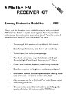
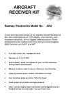
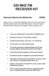
AIRCRAFT BAND
RECEIVER KIT
Ramsey Electronics Model No.
AR1C
Eavesdrop in on the pilots as they trace their way across the sky.
Fascinating listening for all ages and abilities-hears ‘em all, from
jumbos to pipers. This sensitive receiver picks up planes up to
100 miles away. Ideal for arm-chair pilots, student pilots and the
real McCoy pilots!
• Tunes the entire 118 - 136 MHz Air band
• Operates on internal 9 volt battery
• Listen to control towers, centers, and planes en-route
• Very sensitive; picks up planes 100 miles away!
• Great project for all pilots and flight students
• Clear, concise step-by-step instructions carefully guide you
to a finished kit that not only works - but you’ll learn too!
• Reviewed in January 1991 “Kitplanes” magazine
• Add our case and knob set for a finished ‘Pro’ look.
AR1 • 1
PARTIAL LIST OF AVAILABLE KITS
RAMSEY TRANSMITTER KITS
• FM10A FM Stereo Transmitter
• FM25 Synthesized FM Stereo Transmitter
• AM25 Synthesized AM Transmitter
• AM1 AM Transmitter
RAMSEY RECEIVER KITS
• FR1 FM Broadcast Receiver
• AA7 Active Antenna
• SC1 Shortwave Converter
RAMSEY HOBBY KITS
• SG7 Personal Speed Radar
• SS70 Speech Scrambler
• TT1 Telephone Recorder
• SP1 Speakerphone
• MD3 Microwave Motion Detector
• PH10 Peak hold Meter
• LC1 Inductance-Capacitance Meter
RAMSEY AMATEUR RADIO KITS
• HR Series HF All Mode Receivers
• QRP Series HF CW Transmitters
• CW7 CW Keyer
• QRP Power Amplifiers
RAMSEY MINI-KITS
Many other kits are available for hobby, school, scouts and just plain FUN. New
kits are always under development. Write or call for our free Ramsey catalog.
AR1C AIRCRAFT BAND RECEIVER KIT INSTRUCTION MANUAL
Ramsey Electronics publication No. MAR1 Revision C1
First printing: October, 1994
COPYRIGHT ©1994 by Ramsey Electronics, Inc. 590 Fishers Station Drive, Victor, New York
14564. All rights reserved. No portion of this publication may be copied or duplicated without the
written permission of Ramsey Electronics, Inc. Printed in the United States of America.
AR1 • 2
Ramsey Publication No. MAR1
Manual Price Only: $5.00
KIT ASSEMBLY
AND INSTRUCTION MANUAL FOR
AR1C AIRCRAFT
BAND RECEIVER KIT
TABLE OF CONTENTS
Introduction to the AR1C ...................................... 4
What You Can Expect To Hear ............................ 4
Those Fast Talking Pilots and Controllers............ 5
Electronics and Flying .......................................... 6
Circuit Description ................................................ 8
Parts Layout Diagram........................................... 8
Parts List .............................................................. 9
Schematic Diagram .............................................. 11
Assembly Instructions .......................................... 12
Antenna Considerations ....................................... 16
Alignment and Adjustment ................................... 17
“VOR” or “OMNI” Transmissions .......................... 17
Tuning the AR1C.................................................. 18
Enclosure Recommendations .............................. 19
Modifications ........................................................ 20
Troubleshooting.................................................... 20
RAMSEY ELECTRONICS, INC.
590 Fishers Station Drive
Victor, New York 14564
Phone (585) 924-4560
Fax (585) 924-4555
www.ramseykits.com
AR1 • 3
INTRODUCTION TO THE AR1C AVIATION RECEIVER KIT
The Ramsey AR1C Aviation Receiver is characterized by exceptional
sensitivity, image rejection, signal-to-noise ratio and stability, all at economical
Ramsey Kit pricing. It is designed for casual "listening in"- both ground and air
communication, for both commercial airlines and general aviation. If you build
and adjust the AR1C correctly, it will give you years of easy sky-monitoring
enjoyment. Even without using the squelch, you will find it to have much less
background noise than many units costing much more money. This kit project
is especially good for people with an interest in learning more about both
Aviation and Electronics. We consider it "easy" to build, but it is definitely not a
simple short-evening project like many of our other kits. If your first interest is
airplanes, and you're just getting into electronics, please study this manual
completely before starting out. The "once over" will temper the jump-in
enthusiasm and help you understand the task at hand. The AR1C has been
built by folks of all ages and skill levels, and in less time than it takes to fly
solo!
118-135 MHz, WHAT YOU CAN EXPECT TO HEAR
A basic fact about the VHF Aviation Band which even licensed pilots can
overlook or forget is that communications are in the AM mode, not FM, as in
the case of the FM broadcast band immediately below it, and the VHF public
service and ham bands immediately above it.
No matter where you live, you will be able to receive at least the airborne side
of many air traffic communications. If you know where to tune, you'll hear any
aircraft you can see, PLUS planes a hundred miles away and more, since VHF
signals travel "line of sight." An airliner at 35,000 feet altitude in the next state
is still line of sight to your antenna. Similarly, whatever ground stations you
may hear are also determined by this "line of sight" character of VHF
communication. If there are no major obstacles between your antenna and an
airport (tall buildings, hills, etc.), you'll be able to hear both sides of many kinds
of aviation communication. Be prepared for them to be fast and to the point,
and for the same airplane to move to several different frequencies in the span
of a few minutes! Here's a brief listing of the most common types of ground
services with which pilots communicate:
•
•
•
•
Control Tower
Ground Control
Clearance Delivery
ATIS
At most metropolitan airports, a pilot communicates with the FAA on a
AR1 • 4
frequency called "Clearance Delivery" to obtain approval or clearance of the
intended flight plan. This communication is done before contacting ground
control for taxi instructions. From the control tower, ground movements on
ramps and taxiways are handled on the “Ground Control” frequency, while
runway and in-flight maneuvers near the airport (takeoffs, local traffic patterns,
final approaches and landings) are on the “Control Tower” frequency. ATIS, or
"Automatic Terminal Information System" is a repeated broadcast about basic
weather information, runways in use, and any special information such as
closed taxiways or runways. Such a broadcast offers an excellent steady
signal source for initial adjustment of your receiver, if you are close enough to
the airport to receive ATIS.
• Approach Control
• Departure Control
These air traffic radar controllers coordinate all flight operations in the vicinity
of busy metropolitan airport areas.
• ATC Center
When you hear a pilot talking with "Jacksonville Center" or "Indianapolis
Center", you know the aircraft is really enroute on a flight rather than just
leaving or just approaching a destination. A pilot will be in touch with several
different "Regional Centers" during a cross-country flight.
• "Unicom"
Airports without control towers rely on the local "Unicom" frequency dedicated
only to advisory communications between pilots and ground personnel such
as fuel service operators. The people on the ground can advise the pilot on
the status of incoming or outgoing aircraft, but the pilot remains responsible
for landing and takeoff decisions. Typical Unicom frequencies are 122.8 and
123.0 Mhz.
• FAA Flight Service Stations (FSS)
The FAA's network of Flight Service Stations keeps track of flight plans,
provides weather briefings and other services to pilots. Some advisory radio
communication takes place between pilots and a regional"FSS". If there is an
FSS in your local area, but no airport control towers, the FSS radio frequency
will stay interesting.
AR1 • 5
THOSE FAST-TALKING PILOTS AND CONTROLLERS!
We don't want you to blame the Ramsey AR1C if all you hear are short bursts
of words that don't make a lot of sense to you! Aviation communication is
brief, but it is clear and full of meaning. Usually, pilots repeat back exactly
what they hear from a controller so that both know that the message or
instructions were correctly interpreted. If you are listening in, it is hard to track
everything said from a cockpit, particularly in big city areas. Just to taxi, take
off and fly a few miles, a pilot may talk with 6 or 8 different air traffic
control operations, all on different frequencies, all within a few minutes! Here
are the meanings of a few typical communications:
"Miami Center, Delta 545 Heavy out of three-zero for two-five."
Delta Flight 545 acknowledges Miami Center's clearance to descend from 30,000
feet to 25,000 feet altitude. The word "heavy" means that the plane is a jumbo jet
such as 747, DC-10, etc.
"Seneca 432 Lima cleared to outer marker. Contact Tower 118.7."
The local Approach Control is saying that the Piper Seneca with the N-number
(tail number) ending in "432L" is cleared to continue flying an instrument approach
to the outer marker (a precision radio beacon located near the airport) and should
immediately call the airport radio control tower at 118.7 Mhz. This message also
implies that the controller does not expect to talk again with that aircraft.
"Cessna 723, squawk 6750, climb and maintain five thousand."
A controller is telling the Cessna pilot to set the airplane's radar transponder to
code 6750, climb to and fly level at an altitude of 5000 feet.
"United 330, traffic at 9 o'clock, 4 miles, altitude unknown."
The controller alerts United Airlines flight #330 of radar contact with some other
aircraft off to the pilot's left at a 9 o'clock position. Since the unknown plane's
altitude is also unknown, both controller and pilot realize that it is a smaller private
plane not equipped with altitude-reporting equipment.
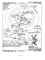
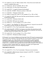
ELECTRONICS & FLYING: DOING IT "BY THE NUMBERS"
As you settle down to build your AR1C, step-by-step, you'll need to "do it by
the numbers", or the receiver won't work. As you look at the schematic and
step-by-step directions, you see that it's important to recognize parts values
and locations by the numbers. Be sure to take the time to do the job right.
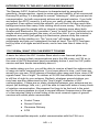
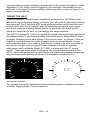
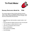
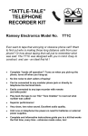
A peek at the sample FAA "instrument approach" chart for medium-large
airports shows that pilots deal with many vitally important numbers and must
do so quickly. Among the numbers on that chart, can you find the air-ground
communications frequencies which can be heard on the AR1C receiver? Can
you find frequencies for uses other than communications?
AR1 • 6
AR1 • 7
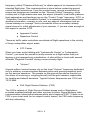
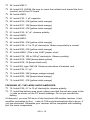
CIRCUIT DESCRIPTION
The antenna is coupled through C1 to a three-section tuned LC filter input
network. 118-135 Mhz signals are amplified by VHF transistor Q1 and fed to
the input of U1, the SA602 mixer-oscillator. L6 and its associated capacitor
network establish the LO (local oscillator) frequency at 10.7 Mhz higher than
the incoming 118-135 Mhz signals. The LO frequency may be tuned across
about 15 Mhz by the varactor tuning network formed by D1 and R1. The 10.7
Mhz difference between the LO and the received signal is fed through the
10.7 Mhz ceramic filter FL1, amplified by Q2 and applied to U2 the MC1350 IF
amplifier IC with AGC input. The 10.7 Mhz IF is peaked by L7, and the AM
audio is demodulated by D2 and fed through the four op-amps of U3, the
LM324, where volume control, AGC output, audio filtering and squelch
functions are managed. The LM386 (U4) audio output is quite low in
background noise and is capable of driving simple communications speakers
to excellent volume levels.
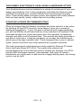
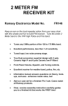
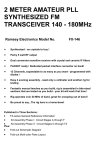
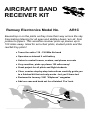
PARTS LAYOUT DIAGRAM
AR1 • 8
PARTS LIST
CAPACITORS
2 3.9 pF ceramic capacitor (C3,C5)
1 10 pF ceramic capacitor (C11)
2 27 pF ceramic capacitor(C12,C14)
3 82 pF ceramic capacitor (C2,C4,C6)
5 .001 µF disc capacitor (marked .001 or 102) (C1,7,8,13,16)
6 .01 µF disc capacitor (marked .01 or 103 or 10nf) (C9,17,19,20,28,30)
2 .1 µF disc capacitor (marked .1 or 104) (C23,C24)
1 .47 µF electrolytic capacitor (C22)
6 4.7 to 10 µF electrolytic capacitor (C10,15,21,25,26,31)
3 100 to 220 µF electrolytic capacitor (C18,27,29)
FIXED RESISTORS
2 270 ohm [red-violet-brown] (R6,R28)
6 1K ohm [brown-black-red] (R5,7,11,18,25,27)
4 10K ohm [brown-black-orange] (R8,12,17,23)
1 22K ohm [red-red-orange] (R26)
2 33K ohm [orange-orange-orange](R13,R22)
7 47K ohm [yellow-violet-orange](R4,9,15,16,20,21,24)
1 100K ohm [brown-black-yellow](R19)
2 1 megohm [brown-black-green] (R10,R14)
SEMICONDUCTORS
1 2SC2498 or 2SC2570A NPN UHF transistor (Q1)
1 2N3904 NPN transistor (Q2)
1 SA602 8pin IC (U1)
1 MC1350 8pin IC (U2)
1 LM324 14pin IC (U3)
1 LM386 8pin IC (U4)
1 BB505 varactor diode (marked BB505. Orange body with black band) (D1)
1 1N270 germanium diode (clear body with black stripe or band) (D2)
1 1N4148 silicon diode (tiny clear body with black band) (D3)
INDUCTORS AND FILTERS
3 pre-wound 2 turn wire coils (L1,L3,L5)
2 .33 uH inductors (either wire wound with orange-orange-silver dots, or
resembling resistors with orange-orange-silver bands) (L2,L4)
1 4-turn slug tuned coil (plastic body) (L6)
1 Shielded 10.7 Mhz transformer (metal can body marked 421F122) (L7)
1 10.7 Mhz ceramic filter (brown molded, 3 leads) (FL1)
CONTROLS, HARDWARE & MISCELLANEOUS
3 10K potentiometers (R1,R2,R3)
1 PC mount DPDT switch (S1)
1 PC mount RCA jack (J1)
1 subminiature phone jack (J2)
AR1 • 9
1 9-volt battery snap connector
1 9-volt battery hold-down clamp
1 AR1C printed circuit board
In ALL PC board assembly steps, our word "INSTALL" means to do this:
• Insert the part, oriented or "pointed" correctly, into its holes in the
PC board.
• If helpful, gently BEND the part's wire leads or tabs to hold it into
place, with the body of the part snugly against the top side
("component side") of the circuit board.
• Solder ALL wires or pins of the part.
• Trim or "nip" all excess wire lengths extending beyond each solder
connection, taking care that wire trimmings do not become lodged
in solder connections.
AR1 • 10
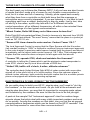
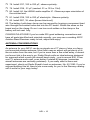
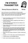
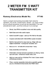
SCHEMATIC DIAGRAM
AR1 • 11
ASSEMBLY INSTRUCTIONS
1. Press S1 firmly into its six holes and solder all six pins. The switch fits
in the board only one way. Be sure the white plastic push button extends
out over the edge of the printed circuit board.
2. Install J1, the RCA-style antenna jack. Solder all 4 points. The jack
presses into the board quite firmly.
3. Install J2, the subminiature phone jack. Solder all 3 points. Be patient
and gentle in inserting, so as not to damage the soldering tabs.
4. Installation of Controls. Your kit contains potentiometers for tuning,
volume and squelch controls. These controls are directly mounted to the
PC board. Insert all three controls, R1, R2 and R3 fully in their positions
and solder the controls firmly. Be sure the mounting tabs are completely
soldered for a good mechanical connection.
ANTENNA INPUT AND PREAMPLIFIER SECTION
5. Install C1, .001 µF disc capacitor (marked .001 or 102).
6. Install C2, 82pF.
7. Install L1, the small pre-wound 2-turn coil. Gently stretch the coil just
enough so that the two ends fit firmly into the PC board holes. Solder
both ends securely.
8. Install L2, .33 µH inductor (orange-orange-silver dots or bands).
9. Install C3, 3.9 pF.
10. Install C4, 82 pF.
11. Install L3, 2 turn pre-wound coil.
12. Install L4, the other .33 µH inductor.
13. Install C5, 3.9 pF.
14. Install C6, 82 pF.
15. Install L5, 2 turn pre-wound coil.
16. Install C7, .001 µF (marked .001 or 102).
17. Clearly identify Q1, the 2SC2498 or 2570A transistor. Do not confuse
it with the other transistor supplied (2N3904). Position Q1 as shown on
the Parts Layout Diagram. Press Q1 snugly into its holes so that only a
minimum amount of wire lead is exposed above the board. In soldering,
do not be afraid to use enough heat to make good connections.
AR1 • 12
18. Install R4, 47K [yellow-violet-orange].
19. Install C8, .001 µF (marked .001 or 102).
20. Install R5, 1K ohms [brown-black-red].
21. Install R6, 270 ohms, [red-violet-brown].
SA602 LOCAL OSCILLATOR-MIXER SECTION
22. Install C9, .01 µF (marked .01 or 103).
23. In installing the SA602 IC, you may think to use an 8-pin DIP socket
rather than soldering directly to the PC board. However, please be aware
that we have seen more service problems due to improper socket
installation than from soldering heat damage to ICs. We recommend that
a socket not be used. Be SURE to orient the IC correctly, with the band
or notch pointed as shown on the Parts Layout Diagram. Install U1,
SA602.
24. Install C10, a 4.7 to 10 µF electrolytic capacitor, the first of 9 such
"polarized" capacitors used in the AR1C. Electrolytic capacitors are
usually marked with a stripe along one edge indicating the negative ( - )
lead, while PC boards generally point out the positive ( + ) hole. Consult
the Parts Layout Diagram and orient the capacitor correctly.
25. Install C11, 10 pF (marked 10 or 10K).
26. Install C12, 27 pF (marked 27 or 27K).
27. Install R8, 10K [brown-black-orange].
28. Install C13, .001 µF (marked .001 or 102).
29. Install R7, 1K [brown-black-red].
30. Install C15, 4.7 to 10 µF electrolytic, observing correct polarity.
31. Install R9, 47K [yellow-violet-orange].
32. Install jumper wire JMP1. Jumper wires act as electronic "bridges"
allowing signals to pass over circuit board traces. Use a piece of scrap
component wire from a previously installed part, bend it into a small "U"
shape, and insert it as you would a component.
33. Install L6, This coil must be seated firmly against the PC board.
Mechanical rigidity is important for the stability of the oscillator.
34. Install D1, BB505 varactor diode (marked BB505). Install it with the
banded end (cathode) pointed towards C14.
35. Install C14, 27 pF.
AR1 • 13
36. Install FL1, the 10.7 MHz ceramic filter. It has three wire leads and
may be installed either way.
37. Install C16, .001 µF (marked .001 or 102).
38. Install R28, 270 ohm [red-violet-brown].
39. Install R10, 1 megohm [brown-black-green].
40. Install Q2, 2N3904. Observe position of flat side.
41. Install R11, 1K [brown-black-red].
42. Install C19 and C20, both .01 µF (marked .01 or 103 or 10nf).
43. Install U2, MC1350. Be sure that the end with the dot or notch is
positioned correctly.
44. Install R25, 1K [brown-black-red].
45. Install R26, 22K [red-red-orange].
46. Install C17, .01 µF (marked .01 or 103 or 10nf).
47. Install L7, the shielded 10.7 MHz IF transformer. Its pins fit into the PC
board only one way. Solder all connections.
48. Install C31, 4.7 to 10 µF electrolytic, observe polarity.
49. Install diode D2, 1N270. It is larger in size than the remaining small
diode and marked with a black band. The banded (cathode) end must be
pointed toward the battery side of the board.
50. Install C30, .01 µF (marked .01 or 103 or 10nf).
51. Install R12, 10K [brown-black-orange].
At this point, you have installed more than half of the PC board components for
one of the more complex of all Ramsey kits. By wiring the receiver in the order
suggested so far, you have already constructed a basic, working singleconversion AM receiver able to tune the aircraft band. With an antenna
connected, R1 installed and DC voltage correctly applied to what has been
wired so far, a sensitive test amplifier connected to the cathode of D2 could let
you hear aviation signals right now. However, we think you'll agree that
completing your receiver is a more intriguing project.
THE LM324 CIRCUITS
52. Install C21, 4.7 to 10 µF electrolytic. Observe correct polarity.
53. Install R13, 33K [orange-orange-orange]. Install R14, 1 megohm
[brown-black-green].
AR1 • 14
54. Install JMP 2.
55. Install U3, LM324. Be sure to orient the notched end toward the front
(control) end of the PC board.
56. Install JMP3.
57. Install C23, .1 µF capacitor.
58. Install R16, 47K [yellow-violet-orange].
59. Install R17, 10K [brown-black-orange].
60. Install R15, 47K [yellow-violet-orange].
61. Install C22, .47 µF, observe polarity.
62. Install JMP5.
63. Install JMP4.
64. Install R24, 47K [yellow-violet-orange].
65. Install C25, 4.7 to 10 µF electrolytic. Make sure polarity is correct.
66. Install R20, 47K [yellow-violet-orange].
67. Install JMP6. (This is the LAST jumper wire!)
68. Install C18, 100 to 220 µF electrolytic. Observe polarity.
69. Install R19, 100K [brown-black-yellow].
70. Install R18, 1K [brown-black-red].
71. Install D3, type 1N4148. Observe orientation of banded end.
72. Install C24, 0.1 µF.
73. Install R22, 33K [orange-orange-orange].
74. Install R23, 10K [brown-black-orange].
75. Install R21, 47K [yellow-violet-orange].
FINISHING UP: THE LM386 AUDIO AMPLIFIER
76. Install C26, 4.7 to 10 µF electrolytic, observe polarity.
77. Install the battery snap wires, taking care that the red wire goes to the
(+) side as shown on the PC board drawings. Do not yet connect the
battery.
At this point, you now DO have a fully-functional AM aviation receiver. A test
amplifier connected to the ( - ) side of C26 would demonstrate this to be so, if
you are interested. Otherwise your receiver will be completed with installing
just five more components.
AR1 • 15
78. Install C27, 100 to 220 µF, observe polarity.
79. Install C28, .01 µF (marked .01 or 103 or 10nf).
80. Install U4, the LM386 audio amplifier IC. Observe proper orientation of
the notched end.
81. Install C29, 100 to 220 µF electrolytic. Observe polarity.
82. Install R27, 1K ohms [brown-black-red].
83. The battery hold-down clamp can be secured by looping a component lead
wire through the bracket holes and into the PC board. Solder the wires on the
board and on the clamp. Do not use too much solder on the clamp or the
battery will not seat fully.
CONGRATULATIONS! If you've made 235 good soldering connections and
have all parts identified and oriented correctly, you now own a working AR1C
Aviation Band Receiver ready to test, adjust and enjoy!
ANTENNA CONSIDERATIONS
An antenna for your AR1C can be as simple as a 21" piece of wire or a fancy
roof-mounted aviation antenna. Most folks near an airport will get plenty of inthe-air action from the wire, but if you're more than a few miles away, a decent
roof-mount job is the way to go. Radio Shack sells an ideal antenna designed
for scanners which covers the aircraft band nicely - cost is around $30. A low
cost TV antenna works well, even better if rotated 90 degrees (remember
aircraft antennas are vertically polarized). If you really want to learn and
experiment, check out Radio Shack's book on antennas, No. 62-1083. If you've
enjoyed building this kit, there's lots more ready for you in the Ramsey catalog call or write for your copy today!
AR1 • 16
ALIGNMENT AND ADJUSTMENT
Alignment of the AR1C receiver consists of simply adjusting L6 for the
desired tuning range and peaking the IF transformer (L7). If you are using a
signal generator, frequency counter or other VHF receiver for calibration,
remember that you want to set the local oscillator frequency 10.7 MHz higher
than the desired signal or range to be received.
Adjustment of the L6 oscillator coil MUST be made with a non-metallic
alignment tool. The use of a metal tool of any kind will detune the coil
drastically, making alignment almost impossible. Also, if you’re receiving FM
broadcast stations, you have the slug tuned too far down in the coil form.
Turn it until it is higher in the form and try again.One other thing that you can
do to improve the operation of your kit is to spread out the three 2 turn coils
at the antenna input, L1, L3, and L5. Stretching these out will give you
greater sensitivity.
Once you know you are receiving aircraft or airport transmissions, adjust the
IF transformer (L7) for best reception. Typically, L7 is adjusted 2-3 turns from
the top of the shield can.
If you don't have any signal reference equipment at home, and are not yet
hearing airplanes, your best bet is to pack up your AR1C and needed tools
and head for the nearest airport! If there is no control tower, don't hesitate to
visit a general aviation service center on the airport grounds. If you've never
done this before, you will probably find it to be a fun and interesting
experience. Ask which are the most active frequencies and adjust L6 and
your front panel Tuning control until you hear the action. A ground service
operator or private pilot may be willing to give you a brief test transmission on
the 122.8 Unicom frequency. Remember, also, that if your airport has ATIS
transmissions, you can get a steady test signal as soon as you are line-ofsight with its antenna.
The AR1C does not produce a loud hiss when no signal is being received
(unlike an FM receiver or expensive AM receiver); this is due to the
somewhat limited amount of IF gain. Increasing the IF gain would produce a
hiss and marginally better sensitivity (about a microvolt) but also require
much more alignment, AGC circuitry, and builder ability - far beyond the
intention of this kit.
"VOR" OR "OMNI" TRANSMISSIONS
If you know of a tall white "cone" structure at your airport or in the middle of a
big farming field, it is useful for you to know that these are VHF navigational
aids operating in the 118-135 MHz frequency range, just below the air-ground
AR1 • 17
communications range, sending a steady signal which may be helpful in initial
alignment. If you tune in such a signal on your receiver, remember that you
will have to increase the local oscillator frequency later in order to listen to air
traffic communications.
TUNING THE AR1C
With the varactor Tuning Control capable of going across 10-15 MHz, and
with pilots and controllers talking so briefly, you will need to get used to tuning
your receiver! You'll find that ANY knob gives smoother tuning than the bare
control shaft, and that a "vernier" dial will make the procedure even easier but at the expense of being able to check up and down the band quickly,
which you might like to do if you're tracking the same airplane.
The AR1C is designed to let you explore the entire communications section of
the aviation band. If you become really interested only in being able to check
a certain frequency such as a nearby FAA control tower, or Unicom, it will be
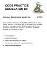
helpful to mark that spot on a dial template such as is reproduced for your
convenience below. If you want a "fine tuning" control, see what you think of
the results you get from wiring a 25-ohm rheostat (as used for speaker
attenuation, such as Radio Shack 271-265) in series with the R1 tuning
control. There are other ways of changing the tuning characteristics of the
AR1C, which will be familiar to radio hams and electronics experimenters, but
they are beyond the primary purpose of the receiver design and this
instruction manual.
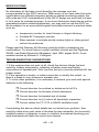
The sample tuning dial templates below may be copied or adapted to provide
a simple "logging scale" for your receiver.
AR1 • 18
THE RAMSEY ELECTRONICS CASE, KNOB & HARDWARE OPTION
Your finished receiver can be installed in a variety of enclosures of your own
design and choosing. Use of the inexpensive and attractive Ramsey case
and knob kit will give your unit that finished look and increase its resale
value. These sturdy black instrument cases are supplied with neatly-lettered
front and rear panels, knobs, rubber feet and mounting screws.
OTHER ENCLOSURE RECOMMENDATIONS
While we believe that the Ramsey enclosure and knob option is a fine value
for finishing off the AR1C receiver, we‘re happy to give you a couple of
additional suggestions . If your first goal is economy and rugged portability,
you will find that the circuit board can be nicely mounted in a standard VHS
videotape storage box, which also gives room for a speaker or earphone
storage, and even a roll of antenna wire. The controls are easily mounted at
one end of such a box. It may be necessary to cut away the molded posts
which secure the tape cassette itself. These storage boxes come in several
styles, so pick one which truly looks practical as a project enclosure.
The most economical metal enclosure nicely suited for Ramsey PC board
kits is the Radio Shack 270-253A. This metal utility cabinet can
accommodate one or two different receiver boards (for example, the AR1C
plus the SR2 shortwave receiver ) plus speaker, with room for various
refinements you might want to add such as a bigger battery pack, fine tuning
control, and so forth.
AR1 • 19
MODIFICATIONS
No alterations of the basic circuit board by the average user are
recommended for the AR1C receiver. While many of our ham radio kits invite
modifications for different frequency bands or special monitoring needs, the
AM mode and VHF considerations of the AR1C design are such that it is best
to let it serve its intended purpose. If you have electronics expertise as well as
specialized aviation related applications, you may wish to use the AR1C as
the foundation for an economical crystal-controlled receiver for practical tasks
such as:
• Inexpensive monitor for local Unicom or Airport Advisory
• Portable ELT frequency monitor
• Slave receiver to activate private runway lights or other groundcontrol conveniences.
Please read the Ramsey Kit Warranty carefully before considering any
modifications. For some help on crystal oscillator circuits and the Signetics
SA602, see Radio-Electronics Magazine, April 1990, pages 49-52, for an
excellent article by Michael A. Covington.
TROUBLESHOOTING SUGGESTIONS
1. If the receiver does not work at all, check the obvious things first and
carefully: battery wire polarity, soldering of battery wires and switch,
connections to speaker jack. Also, be sure that you correctly installed ALL the
jumper wires!
2. If the operation is erratic, a solder connection is usually the culprit - or
there's a break in your antenna or speaker wire.
3. To solve other problems, it is necessary to recheck your work with special
attention to the following:
Correct direction for notched or dotted end of all ICs.
Correct direction for flat side of both transistors.
Correct direction for banded end of diodes.
Correct direction for [+] side of all electrolytic capacitors.
Correct values for C11,C12 in SA602 oscillator circuit
If rechecking the above critical details has not solved your problem, then
carefully check every part value in the step-by-step assembly. An incorrectly
installed resistor or capacitor is easy to overlook; sometimes checking your
work backwards will make the error more obvious.
AR1 • 20
4. Operation of the local oscillator can be verified with a simple VHF receiver
or frequency counter. Remember that it is supposed to be set to a frequency
10.7 MHz above the desired listening range. If the oscillator works, only a
defective or incorrectly installed part can prevent the rest of the receiver
circuit from functioning.
CONCLUSION
We sincerely hope that you will enjoy the use of this Ramsey product. As
always, we have tried to compose our manual in the easiest, most “user
friendly” format that is possible. As our customers, we value your opinions,
comments, and additions that you would like to see in future publications.
Please submit comments or ideas to:
Ramsey Electronics Inc.
Attn. Hobby Kit Department
590 Fishers Station Drive
Victor, NY 14564
And once again, thanks from the folks at Ramsey!
AR1 • 21
AR1 • 22
The Ramsey Kit Warranty
Please read carefully BEFORE calling or writing in about your kit. Most problems can be solved
without contacting the factory.
Notice that this is not a "fine print" warranty. We want you to understand your rights and ours too! All
Ramsey kits will work if assembled properly. The very fact that your kit includes this new manual is your
assurance that a team of knowledgeable people have field-tested several "copies" of this kit straight
from the Ramsey Inventory. If you need help, please read through your manual carefully, all information
required to properly build and test your kit is contained within the pages!
1. DEFECTIVE PARTS: It's always easy to blame a part for a problem in your kit, however, customer
satisfaction is our goal, so in the event that you do have a problem, take note of the following. Before
you conclude that a part may be bad, thoroughly check your work. Today's semiconductors and passive
components have reached incredibly high reliability levels, and its sad to say that our human
construction skills have not! But on rare occasion a sour component can slip through. All our kit parts
carry the Ramsey Electronics Warranty that they are free from defects for a full ninety (90) days from
the date of purchase. Defective parts will be replaced promptly at our expense. If you suspect any part
to be defective, please mail it to our factory for testing and replacement. Please send only the defective
part(s), not the entire kit. The part(s) MUST be returned to us in suitable condition for testing. Please be
aware that testing can usually determine if the part was truly defective or damaged by assembly or
usage. Don't be afraid of telling us that you 'blew-it', we're all human and in most cases, replacement
parts are very reasonably priced.
2. MISSING PARTS: Before assuming a part value is incorrect, check the parts listing carefully to see if
it is a critical value such as a specific coil or IC, or whether a RANGE of values is suitable (such as "100
to 500 uF"). Often times, common sense will solve a mysterious missing part problem. If you're missing
five 10K ohm resistors and received five extra 1K resistors, you can pretty much be assured that the '1K
ohm' resistors are actually the 'missing' 10 K parts ("Hum-m-m, I guess the 'red' band really does look
orange!") Ramsey Electronics project kits are packed with pride in the USA. If you believe we packed
an incorrect part or omitted a part clearly indicated in your assembly manual as supplied with the basic
kit by Ramsey, please write or call us with information on the part you need and proof of kit purchase.
3. FACTORY REPAIR OF ASSEMBLED KITS:
To qualify for Ramsey Electronics factory repair, kits MUST:
1. NOT be assembled with acid core solder or flux.
2. NOT be modified in any manner.
3. BE returned in fully-assembled form, not partially assembled.
4. BE accompanied by the proper repair fee. No repair will be undertaken until we have received the
MINIMUM repair fee (1/2 hour labor) of $25.00, or authorization to charge it to your credit card account.
5. INCLUDE a description of the problem and legible return address. DO NOT send a separate letter;
include all correspondence with the unit. Please do not include your own hardware such as: nonRamsey cabinets, knobs, cables, external battery packs and the like. Ramsey Electronics, Inc.,
reserves the right to refuse repair on ANY item in which we find excessive problems or damage due to
construction methods. To assist customers in such situations, Ramsey
Electronics, Inc., reserves
the right to solve their needs on a case-by-case basis.
The repair is $50.00 per hour, regardless of the cost of the kit. Please understand that our technicians
are not volunteers and that set-up, testing, diagnosis, repair and repacking and paperwork can take
nearly an hour of paid employee time on even a simple kit. Of course, if we find that a part was
defective in manufacture, there will be no charge to repair your kit (But please realize that our
technicians know the difference between a defective part and parts burned out or damaged through
improper use or assembly).
4. REFUNDS: You are given ten (10) days to examine our products. If you are not satisfied, you may
return your unassembled kit with all the parts and instructions and proof of purchase to the factory for a
full refund. The return package should be packed securely. Insurance is recommended. Please do not
cause needless delays; read all information carefully.
AR1 • 23
Aircraft Band ReceiverQuick Reference Page Guide
Introduction to the AR1C ............................4
What You Can Expect To Hear ..................4
Circuit Description ......................................8
Parts Layout Diagram.................................8
Parts List ....................................................9
Schematic Diagram ....................................11
Assembly Instructions.................................12
Antenna Considerations .............................16
Alignment and Adjustment..........................17
“VOR” or “OMNI” Transmissions ................17
Tuning the AR1C ........................................18
Troubleshooting..........................................20
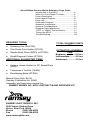
REQUIRED TOOLS
•
•
•
•
Soldering Iron (WLC100)
Thin Rosin Core Solder (RTS12)
Needle Nose Pliers (MPP4 or RTS05)
Small Diagonal Cutters (RTS04)
ADDITIONAL SUGGESTED ITEMS
•
Helping Hands Holder for PC Board/Parts
(HH3)
•
•
Technician’s Tool Kit (TK405)
Desoldering Braid (RTS08)
TOTAL SOLDER POINTS
235
ESTIMATED ASSEMBLY
TIME
Beginner............... 6.0 hrs
Intermediate......... 4.0 hrs
Advanced ............. 3.0 hrs
Manual Price Only: $5.00
Ramsey Publication No. MAR1
Assembly and Instruction manual for:
RAMSEY MODEL NO. AR1C AIRCRAFT BAND RECEIVER KIT
RAMSEY ELECTRONICS, INC.
590 Fishers Station Drive
Victor, New York 14564
Phone
(585) 924-4560 AR1 • 24
Fax
(585) 924-4555
www.ramseykits.com