1
6 METER FM
RECEIVER KIT
Ramsey Electronics Model No.
FR6
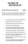
Check out the 6 meter action with this simple and fun to build
FM receiver. Receive crystal-clear signals from thousands of
miles away! Six meters is a fascinating band! Tune the entire 6
Meter band or the VHF low Police and Fire band.
•
Tunes any 5 MHz portion of the 40 to 60 MHz band.
•
Excellent performance, less than 1 uV sensitivity.
•
Tuned input, low noise preamp stage.
•
True Dual-conversion superhet design with 2 pole
Ceramic High IF and 6 pole Ceramic low IF filters!
•
Front Panel Volume, Squelch, and Tuning controls.
•
Excellent receiver for beginners and seasoned pros!
•
Informative manual answers questions on theory, hookups, and uses - enhances resale value, too!
•
Add our case set for a finished ‘Pro’ look. Cases match
all Ramsey products.
•
Clear, concise assembly instructions carefully guide
you to a finished kit that works the FIRST time!
RAMSEY TRANSMITTER KITS
· FM100B Professional FM Stereo Transmitter
· FM25B Synthesized Stereo Transmitter
·AM1, AM25 AM Transmitters
· TV6 Television Transmitter
RAMSEY RECEIVER KITS
· FR1 FM Broadcast Receiver
· AR1 Aircraft Band Receiver
· SR2 Shortwave Receiver
· AA7 Active Antenna
· SC1 Shortwave Converter
RAMSEY HOBBY KITS
· SG7 Personal Speed Radar
· SS70A Speech Scrambler
· SP1 Speakerphone
· WCT20 Wizard Cable Tracer
·ECG1 Heart Monitor
·LABC1 Lead Acid Battery Charger
·IG7 Ion Generator
· CT255 Compu Temp Digital Binary Thermometer
· LC1 Inductance-Capacitance Meter
RAMSEY AMATEUR RADIO KITS
· HR Series HF All Mode Receivers
· QRP Series HF CW Transmitters
· DDF1 Doppler Direction Finder
· CPO3 Code Practice Oscillator
· QRP Power Amplifiers
RAMSEY MINI-KITS
Many other kits are available for hobby, school, Scouts and just plain FUN. New
kits are always under development. Write or call for our free Ramsey catalog.
FR-10 10 METER FM RECEIVER KIT INSTRUCTION MANUAL
Ramsey Electronics publication NO. MFR6 Rev. E1
First printing: January 1992
COPYRIGHT 1992 by Ramsey Electronics, Inc. 590 Fishers Station Drive, Victor, New York
14564. All rights reserved. No portion of this publication may be copied or duplicated without the
written permission of Ramsey Electronics, Inc. Printed in the United States of America.
FR6 • 2
Ramsey Publication No. MFR6
Price $5.00
KIT ASSEMBLY
AND INSTRUCTION MANUAL FOR
FR6 6 METER
FM RECEIVER KIT
TABLE OF CONTENTS
Introduction to the FR6 ..................
Circuit Description .........................
Parts List........................................
Simplified Block Diagram ..............
Parts Layout Diagram....................
Schematic Diagram .......................
FR6 Assembly Instructions ...........
Testing and Alignment...................
Enclosure Ideas.............................
Troubleshooting Guide ..................
Notes for Advanced Users ............
Ramsey Kit Warranty ....................
FR6 • 3
4
5
6
8
9
10
11
18
20
21
22
23
INTRODUCTION
FM and repeaters on 6 meters? You bet!
There's not a lot to say about using the FR6 receiver once its been correctly
built and aligned. If 6 meters is "dead”, it resembles the usual 2 meter action.
If 6 meters is "hot", you’ll find an amazing variety of crystal-clear FM signals
from many thousands of miles away! If there are local 6 meter repeaters in
your area, the FR6 will be just as active as the local repeater gang.
Since the FR6 “hears” only FM, the various SSB and CW signals on the band
will not be properly demodulated as to be intelligible.
This receiver is a good project for amateurs wishing to become more familiar
with 6 meter FM before choosing a transceiver, or for those active on 6 who
want an inexpensive receiver to take on trips, keep in a briefcase or to watch
for band openings.
Most Ramsey Electronic Kits can be classified as "Skill Level 1" if we use the
old Heathkit guidelines for ease of assembly. That means that our kits are
intended to be successful for first-time kit builders. This FR6 FM Receiver is
best regarded as a "Skill Level 2" project, (or least Level 1.46!) and should
not be taken lightly, even by experienced, licensed radio amateurs.
Still, this step-by-step manual is written with the beginner in mind, because
we are well aware of the fascination that Six Meters and its maze of
repeaters holds for newcomers, which means this could be your very first kit
project. The same holds true for those who just want to peek in on LOW VHF
public service communications without the cost of a scanner. To be honest,
we'd like to see first-time builders start out with an easier kit such as the
Ramsey HR40 Forty Meter receiver before assembling the FR6, but we are
confident that you can construct the FR6 successfully if you follow this
manual carefully and patiently.
Before beginning the project or even studying the circuit description, it is
worthwhile to develop some prior respect for how much receiver is packed
onto the circuit board. The nine semiconductor devices (diodes, transistors
and IC chips) give the equivalent of about 30 or more transistors diodes. And,
in addition to four inductors, a crystal and two ceramic filters, there are nearly
60 capacitors and resistors. Surely, all that should result in a decent receiver!
You could easily spend twice the money plus hours of time trying to gather
the equivalent parts from catalogs and still need to make your own circuit
board.
FR6 • 4
BUILDING YOUR FR6 KIT
There are just over 200 solder connections on the FR6 printed circuit board.
That means your work could be 99% excellent and you could STILL have 2
or 3 cold solder points or solder bridges. Since this circuit is more
sophisticated than a direct-conversion HF receiver or a simple transmitter, a
beginner or casual amateur could have a harder time tracing a problem due
to a poor solder connection. Therefore, PLEASE take us seriously when we
say that good soldering is essential to the proper operation of your receiver!
Use a 25-watt soldering pencil with a clean, sharp tip.
Use only rosin-core solder intended for electronics use.
Use bright lighting. A magnifying lamp or bench-style magnifier may be
helpful.
Do your work in stages, taking breaks to check your work.
Carefully brush away wire cuttings so they don't lodge between solder
connections.
FR6 CIRCUIT DESCRIPTION
VHF signals from the antenna are amplified through the tuned input circuit
(L1,C3 and L2,C4) by Q1, a microwave bipolar transistor. Q1's output is fed
to the input of the SA602 IC, an efficient single-package (8-pin DIP) mixerproduct detector-oscillator. The tuneable oscillator section of the SA602 is
aligned to operate at 10.7 MHz higher than the signal fed and amplified by
Q1. For example, to receive 50-54 MHz signals, the oscillator must tune 60.7
to 64.7 MHz in order for the SA602's mixing capability to produce a steady
10.7 MHz output signal to the rest of the circuit. The oscillator frequency is
determined by L3 and its associated capacitors, and varied by the varactor
tuning network using D1 and varied by R1.
The output from pin 4 of the SA602 passes through a ceramic 10.7 MHz filter,
amplified by transistor Q2 and applied to input pin 18 of U2.
Q3 provides AFC (Automatic Frequency Control) by keeping the local
oscillator of U1 from drifting away from an incoming signal. This is
accomplished by tuning the varactor circuit in the direction opposite the drift.
The MC3359 IC has an internal oscillator controlled by the 10.24 MHz crystal.
The 10.24 MHz signal is mixed with the 10.7 MHz input from U1 to convert
down to the low IF of 450 KHz. The 450 KHz IF is filtered by FL2 and then
amplified by a limiting amplifier in U2. Audio demodulation takes place in the
quadrature detector, with L4 adjusting the detector.
The audio modulation is detected in U2, and the background noise is used to
control the squelch. U3 amplifies the audio output from pin 10 of U2 to a
FR6 • 5
practical level for speaker or headphone operation. Pin 16 of U2 will ground
the input of U3 when the squelch is closed.
L4, a 450 KHz IF coil, permits adjustment of the 90-degree voltage-current
phasing ("quadrature") of FL2's output to the FM detector demodulator (pin 8
of the MC3359).
PARTS LIST
Inductors
2 .15 uH inductors [looks like a resistor with brown-green-silver
bands] (L1,L2)
1 slug-tuned turn coil [blue color] (L3)
1 shielded transformer coil [marked LB 53303] (L4)
Semiconductors and IC's
1 2SC2498 or 2SC2570A transistor (Q1)
3 2N3904 transistor (Q2,Q3,Q4)
1 SA602 8-pin IC (U1)
1 MC3359 18-pin FM receiver IC (U2)
1 LM386 8-pin audio amplifier IC (U3)
1 Varactor diode, BB505 [orange body marked BB505] (D1)
1 1N4148 signal diode (D2)
Special Components
1 10.24 MHz Crystal (Y1)
1 10.7 MHz ceramic filter [brown, molded, 3 leads] (FL1)
1 450 KHz ceramic filter [black, square] (FL2)
Fixed Resistors
1 2 ohm [red-black-gold] (R22)
3 270 ohm [red-violet-brown] (R6,9,20)
1 470 ohm [yellow-violet-brown] (R5)
2 1K ohm [brown-black-red] (R11,12)
3 10K ohm [brown-black-orange] (R7,17,19)
1 18K ohm [brown-gray-orange] (R18)
1 33K ohm [orange-orange-orange] (R14)
4 47K ohm [yellow-violet-orange] (R4,8,13,21)
1 100K ohm [brown-black-yellow] (R16)
1 470K ohm [yellow-violet-yellow] (R15)
1 1 megohm [brown-black-green] (R10)
Capacitors
1 4.7 or 5 pF (C2)
2 10 pF (C1,5)
1 22 pF (C19)
FR6 • 6
4
4
1
6
8
1
1
3
4
62 pF (C3,4,9,10)
100 pF [marked 100, 101, or 101K] (C6,11,12,22)
220 pF [marked 220 or 221] (C18)
.001 uF [marked .001 or 102 or 1 nF] (C7,8,20,23,24,25)
.01 uF [marked .01 or 103 or 10 nF] (C13,16,17,21,26,28,29,31)
.1 uF [marked .1 or 104] (C34)
1.0 uF electrolytic (C27)
4.7 or 10 uF electrolytic (C15,30,36)
100 to 220 uF electrolytic (C14,32,33,35)
Controls and Hardware
1 Printed circuit board
3 10K ohm potentiometer (R1,R2,R3)
1 DPDT push switch (S1)
1 PC mount RCA jack (J1)
1 PC mount subminiature speaker jack (J2)
1 9-volt battery bracket
1 9-volt battery snap-on clip
REQUIRED, NOT SUPPLIED
1 9-volt alkaline battery
1 VHF antenna with cable terminated in RCA-style plug or adapter
1 Speaker or headphones
NOTE CONCERNING THE AUDIO OUTPUT JACK
Your receiver kit is supplied with a standard subminiature 2.5 mm (3/32")
audio output jack, which mates with commonly available earphone plugs and
adapters available at Radio Shack, such as 274-290 (plug) or 274-327
(adapter for 1/8" mono plug). If you prefer to use another size and style jack,
we suggest that you still install the original jack and then wire your own jack in
parallel with it rather to rough up the PC board to accommodate your jack.
FR6 • 7
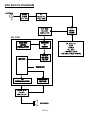
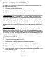
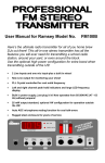
FR6 BLOCK DIAGRAM
U2, 3359
FR6 • 8
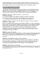
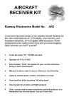
FR6 PARTS LAYOUT DIAGRAM
FR6 • 9
FR6 • 10
RAMSEY “Learn-As-You-Build” KIT ASSEMBLY:
We have a twofold "strategy" for the order of the following kit assembly steps.
First, we install parts in physical relationship to each other, so there's minimal
chance of inserting wires into wrong holes. Second, whenever possible, we
install in an order that fits our "Learn-As-You Build" Kit building philosophy.
FOR EACH PART, OUR WORD "INSTALL" ALWAYS MEANS THESE
STEPS:
1. Pick the CORRECT part value to start with.
2. Insert it into the CORRECT PC board location.
3. ORIENT it correctly, which means: PLEASE follow the PC board drawing
and the written directions for ALL parts where there's a right way AND a
wrong way to solder it in. (Diode bands, electrolytic capacitor polarity,
transistor shapes, dotted or notched ends of IC's, and so forth.)
4. Solder ALL connections unless directed otherwise. Use enough heat and
solder flow for clean, shiny, completed connections. Don't be afraid of
ANY pen-style soldering iron having enough heat to damage a
component.
5. Trim or "nip" excess wire lengths after soldering.
NOTE: Save some of the longer wire scraps nipped from resistors and
capacitors. These will be used to form wire jumpers (JMP1, etc.) to be
soldered in just like parts during these construction steps.
Now, let's start building!
1. Press S1 firmly into its six holes and solder all six pins. The switch fits
the board only one way. Ignore the other set of six solder connectors on
the switch.
2. Install J1, the RCA-style antenna jack. Solder all 4 points.
3. Install J2, the subminiature phone jack. Solder all three points. Be
gentle and patient in inserting, so as not to damage the solder tabs.
4. Install controls R1, R2 and R3. Insert the three PC mounted controls
into their positions. Check that the controls are pressed in firmly and
straight against the top of the board. Solder the three center pins and
then the two larger mechanical mounting tabs. Use enough solder for a
solid connection.
Also, if you plan to use an enclosure other than the custom Ramsey enclosure
and knob kit, you may wish to locate the controls differently than provided by
FR6 • 11
the PC board. In this case, the control lugs are wired to the PC board using
your own insulated hookup wire, kept as short as possible for neat installation.
All "directions" on the PC board (ie: right, left, above, below and so forth)
assume orientation of your board as shown in the parts layout diagram.
Therefore the rear of the board (connectors) is the lower end, and the front
(controls) is the upper end.
1. ANTENNA INPUT AND TUNED RF PREAMPLIFIER
❒
5. Install C1, 10 pF disc capacitor.
❒
6. Install C2, 4.7 or 5 pF.
❒
7. Install C3, 62 pF.
❒
8. Install L1, .15 uH inductor [looks like a resistor with a green colored
body with brown, green, and silver bands].
❒
9. Install C4, 62 pF.
❒
10. Install L2, just like L1 above.
❒
11. Install C5, 10 pF.
❒
12. Clearly identify Q1, the 2SC2498 or 2SC2570A transistor. Do not
confuse it with the other transistors supplied.
❒
13. Position Q1 as shown on the PC board layout, with the flat side facing
to the right, toward the middle of the board. Press the transistor snugly
into the PC board so that only a minimum amount of wire lead is exposed
above the board. In soldering, don't be afraid to use enough heat to make
good clean connections.
❒
14. Install R4, 47K. [yellow-violet-orange] just to the left of Q1.
❒
15. Install C6, 100 pF [marked 100, 101, or 101K].
❒
16. Install R5, 470 ohms [yellow-violet-brown].
2. SA602 OSCILLATOR-MIXER and VARACTOR TUNING
❒
17. Install R6, 270 ohms [red-violet-brown].
❒ 18. Install C7, a .001 uF bypass capacitor [marked .001, 102, or 1 nF].
In installing the SA602 IC, you may wish to use an 8-pin DIP socket rather
than soldering the IC directly to the board. Reasons for doing this might
include the peace of mind of beginners afraid of damaging the IC, or
experienced builders testing the merits of the SA602's cousin, the SE602.
However, please be aware that we have seen more service problems with
FR6 • 12
improper socket insertion than from soldering heat damage to IC's. Even if this
is your first IC, don't be afraid to use enough heat to make 8 clean
connections, but DO be sure to correctly orient the end marked by a band,
dot, or notch. Before soldering, make sure that the IC or socket is perfectly flat
against the top of the PC board.
❒
19. Install U1, the SA602 in accord with the preceding directions.
❒
20. Install the FL1 ceramic filter. This component looks like a capacitor
with 3 leads and may be installed either way.
❒
21. Install jumper wire JMP4. Use a scrap component lead wire bent into
a small loop that connects the two PC board holes. Jumpers act as
"bridges" over PC board traces underneath.
❒
22. Install C8, .001 uF [marked .001, 102, or 1 nF].
❒
23. Install C10, 62 pF.
❒
24. Install R7, 10K [brown-black-orange].
❒
25. Install C9, 62 pF.
❒
26. Install C11, 100 pF [marked 100, 101, or 101K].
❒
27. Installation of L3. It is important that the body of this coil be snug
against the PC board for mechanical stability, which directly affects the
frequency stability of the receiver. Make good, solid solder connections!
❒
28. Install C12, 100 pF [marked 100, 101, or 101K].
❒
29. Install varactor diode D1, marked BB505. It is important to orient this
part as shown in the parts layout diagram.
❒
31. Install R8, 47K ohms [yellow-violet-orange].
❒
32. Install R9, 270 ohms [red-violet-brown].
❒
33. Install C13, .01 uF (marked .01 or 103 or 10 nF).
❒
34. Installation of C14. This is the first of the electrolytic or "polarized"
capacitors that you will install. This means these capacitors have a
positive (+) and negative (-) side and therefore a right way and wrong way
of installation. Ordinarily, only the negative side is marked on the capacitor
body, a dark band with the (-) sign clearly shown. The value of C14 is not
critical and may be any value from 100 to 220 uF.
❒
35. Install C14, 100 to 220 uF, observing correct polarity.
❒
36. Install C15, 4.7 or 10 uF, observing correct polarity.
FR6 • 13
❒
37. Install jumper JMP1.
❒
38. Install jumper JMP3.
PROGRESS SUMMARY
So far, you have wired the tuned input from the antenna, the RF preamplifier,
and the SA602 mixer-oscillator, including the varactor tuning circuit. The work
you have done so far has actually formed a simple receiver capable of tuning
in VHF signals of all kinds and converting them to a low-level 10.7 MHz output
to be amplified by Q2. This is a good time to review the steps completed so far
before proceeding. Due to the many functions of the MC3359 FM receiver IC,
further assembly steps will be in the order of easiest parts installation.
3. TRANSISTOR COUPLING & AFC CIRCUITS, VOLUME & SQUELCH
CONTROLS
❒
39. Install Q2, a 2N3904 transistor. Observe correct positioning of the flat
side.
❒
40. Install R13, 47K ohms [yellow-violet-orange].
❒
41. Install C20, .001 uF [marked .001, 102, or 1 nF].
❒
42. Install R12, 1K ohms [brown-black-red].
❒
43. Install Q3, 2N3904 transistor.
❒
44. Install R10, 1 megohm [brown-black-green].
❒
45. Install R11, 1K ohms [brown-black-red].
❒
46. Install R22, 2 ohms [red-black-gold].
❒
47. Install C29, .01 uF [marked .01, 103, or 10 nF].
❒
48. Install C30, 4.7 or 10 uF electrolytic, observe correct polarity.
❒
49. Install R18, 18K ohms [brown-gray-orange].
FR6 • 14
❒
50. Install C28, .01 uF [marked .01, 103, or 10 nF].
❒
51. Install R19, 10K ohms [brown-black-orange]
❒
52. Install jumper wire, JMP2.
❒
53. Install C34, .1 uF [marked .1 or 104].
❒
54. Install R21, 47K ohms [yellow-violet-orange].
❒
55. Install C35, 100 to 220 uF electrolytic, observe polarity.
❒
56. Install R20, 270 ohms [red-violet-brown].
❒
57. Install Q4, 2N3904 transistor.
4. MC3359 FM IC and ASSOCIATED COMPONENTS
❒
58. Install R17, 10K ohms [brown-black-orange].
❒
59. Install R14, 33K ohms [orange-orange-orange].
❒
60. Install C24, .001 uF [marked .001, 102, or 1 nF].
❒
61. Install C25, .001 uF [marked .001, 102, or 1 nF].
❒
62. Install C26, .01 uF [marked .01, 103, 10 nF].
❒
63. Install L4, the 455 KHz quadrature coil [marked LB53303], soldering
the two pins and the two mounting tabs.
❒
64. Installation of MC3359 IC. As in the case of the NE602 IC, you could
choose to install an 18-pin IC socket rather than soldering the IC directly.
Re-read the discussion of IC sockets offered for the installation of U1.
Larger IC's such as the MC3359 require considerably more care in socket
insertion. Notice that the end of the IC marked by a band, dot, or notch
must be oriented correctly as shown on the parts layout diagram. Solder
each of the 18 connections carefully. Make sure you have good lighting as
well as good technique to make sure that no solder "bridges" flow between
the connections.
❒
65. Install C22, 100 pF (marked 100, 101, or 101K).
❒
66. Install C16, .01 uF [marked .01 or 103 or 10 nF].
❒
67. Install C17, .01 uF [marked .01 or 103 or 10 nF].
❒
68. Install C21, .01 uF [marked .01 or 103 or 10 nF].
❒
69. Install C18, 220 pF [marked 220 or 221].
FR6 • 15
❒
70. Install C19, 22 pF.
❒
71. Install Y1, the 10.24 MHz. crystal. No special procedure is required.
Simply press the crystal firmly into its holes as far as it will go, and make
good solder connections.
❒
72. Install FL2, the 450 KHz filter. Its three leads are delicate and fit in
only one way.
❒
73. Install C23, .001 uF [marked .001, 102, or 1 nF].
❒
74. Install C27, 1 uF electrolytic, observe correct polarity.
❒
75. Install D2, the 1N4148 signal diode, observe correct orientation of the
banded cathode end. Be sure you correctly identified D2 and did not
confuse it with the varactor diode already installed.
❒
76. Install R16, 100K ohms [brown-black-yellow].
❒
77. Install R15, 470K ohms [yellow-violet-yellow].
5. FINAL CONNECTIONS: THE LM386 AUDIO IC STAGE
You now have a working FM receiver ready for adjustment. The output of the
MC3359 FM IC simply needs to be boosted to listening level. A few more
connections, and your receiver will be ready for adjustment and testing! Now
would be a good time to review some of your previous work and also to make
sure you have on hand what you'll need for testing: antenna, fresh battery,
earphone or speaker with correct plug or adapter.
❒
78. Review the instructions for installing U1 and U2. Insert the LM386 IC
(U3) with the band or dot oriented correctly. Solder the 8 connections.
❒
79. Install C32, a 100 to 220 uF electrolytic, observe correct polarity.
❒
80. Install C31, .01 uF (marked .01, 103, or 10 nF).
❒
81. Install C36, 4.7 or 10 uF electrolytic, observe polarity.
❒
82. Install C33, 100 to 220 uF electrolytic, observe polarity.
FR6 • 16
❒
83. Install the battery snap terminal in the two holes below S1, making
sure that the positive (red) lead is inserted into the (+) hole on the PC
board.
❒
84. The battery bracket may be attached in a variety of ways. A wire
jumper can be passed through the two holes on the PC board, then both
ends soldered on the underside of the board. You may prefer to use very
small screws or even a double-sided mounting adhesive strip or glue. In
using such methods, make sure that the battery will not block the PC
board's mounting hole in its vicinity.
Wiring of the PC board is now complete. If you have the the patience, we
suggest a short break. Then take a magnifying lens and a bright light and
examine all your solder joints, touching up any connection which appears less
than perfect. Make sure all excess leads have been trimmed, and that one is
not bent back flat against the board, possibly causing a short. Brush the solder
side of the board with a stiff brush to make sure that no loose wire trimmings
or solder drippings (tsk tsk) are lodged between connections.
FR6 • 17
TESTING, ALIGNMENT AND ADJUSTMENT
To prepare the FR6 FM VHF Receiver for reliable monitoring operation, you
will need these basic tools:
1. A useful 6 meter signal source.
2. Hexagonal, non-metallic coil slug alignment tool for L3.
3. Small screwdriver to adjust L4.
1. Signal source: This signal can be from your test bench equipment or from
a "live" source such as a local repeater. The "live" signals are best for finetuning, but they also have that VHF communications character of being fast
and to the point. Good test bench signal sources include your own 6-meter
tranceiver, if you are licensed to use it, a signal generator or grid-dip oscillator.
If TV channel 2 (54-60 MHz) is active in your area, you may use its
characteristic video sync “buzz” as an indicator of receiver operation. Do not
expect to hear the audio portion clearly, since TV sound signals are fairly
wideband FM (75 KHz) which is too much for our narrow-band FM ceramic IF
filter.
2. L3 Alignment Tool: If you do not already have a set of plastic or nylon coil
alignment tools and do expect to try further Ham radio or electronic hobby
projects, such tools are worth having and can be found inexpensively at any
electronics store including Radio Shack. While a metal Hex key wrench can fit
the coil slug, the metal itself would damage the coil inductance drastically and
therefore should not be used. With patience and sandpaper, a useable tool
might be formed from a wood or plastic rod.
ALIGNMENT PROCEDURE
1. Make sure the power switch is off.
2. Connect the antenna, earphone or speaker and battery.
3. Turn the slug of L3 until it is even with the top of coil the form.
4. Now, turn the slug of L3 clockwise 1 1/2 turns back into the form.
5. Turn the slug of L4 until it is flush with the top of the coil and then turn it
2 turns back into the coil.
6. Turn all three controls to the left, fully counterclockwise.
FR6 • 18
7. Turn the power ON.
8. Turn R2 (Volume control) until you hear some noise.
9. Adjust L4 for maximum noise in the speaker.
Further alignment now consists of adjusting the oscillator coil L3 to permit the
tuning control (R3) to cover the 5 MHz. segment between 50 and 54 MHz of
primary interest to you. Assuming you wish to adjust for the Six Meter
Amateur Band, adjust L3 until you hear your intended test signal.
If you are a beginner with no license or other equipment, any Ham operator
with a 6-meter transceiver should be willing to give you the test signal and
extra help that you need. The FR6 is very sensitive, so operate the transceiver
on low power on a simplex frequency from a distance of at least across the
room. An 8" piece of wire will be a sufficient receiving antenna for such tests.
If you don't know any Hams, visit a friendly two-way radio service center to
get close to the test signal you need!
RECEIVER SENSITIVITY
Your FM receiver features sensitivity under 1 uv. Radio Hams constantly
marvel at how an FR6 displayed at hamfests tunes in dozens of hand-held
QSO's on the premises without an antenna connected! You can expect to
monitor local repeater and simplex transmissions easily, using a simple
groundplane style antenna. The receiver also responds very well to the
addition of a low-noise pre-amplifier such as the Ramsey SA7/PR2. A new
and versatile receiver accessory is the Ramsey AA7 HF-VHF Active Antenna,
which doubles as a preamplifier with other antennas in addition to the
excellent performance of its own whip.
Six meters is generally a daylight hours band. If you finish building your FR6
at midnight, please wait until sunrise before you expect to hear much of
anything. Quite frankly, if there are no local 6 meter operators, you may have
to wait days until the band opens up. However, whenever 6 meters is “hot”,
especially during the summer months, you’ll be amazed at how many stations
will “boom” in from great distances, many running very low power!
ADDING AN LED POWER "ON" INDICATOR
For many people, a pilot lamp to indicate "power on" is more than a nice
touch. They expect it and depend on it, reminding us that "real radios glow in
the dark!" Adding a simple LED power-on indicator to your Ramsey kit
receiver is easy. All you need is the LED itself and a small 1K to 2.2K resistor.
FR6 • 19
Study the PC traces between the positive battery supply wire and the on-off
switch. The unused connectors on top of your switch are an ideal point to get
the + DC voltage needed for the anode (longer lead) of the LED. Plan where
and how you wish to install the LED in your enclosure.
Locating the LED immediately above the on-off switch is logical and ideal. The
simplest way to make a good installation is to drill a neat hole just slightly
smaller than the diameter of the LED. Then, enlarge the hole a little bit at a
time, just enough to let the LED be pressed in and held firmly. The resistor
may be connected to either the anode or cathode of the LED, but the anode
MUST go to + DC, with the cathode connected to the nearest common ground
point. If you are wondering why we did not include these pennies worth of
parts with your kit, you can believe any of the following reasons:
(1) We wanted to stretch your battery budget: with the LED drawing about 6
ma, how long will your battery last if you leave your receiver on for a few days,
just like we leave our computers and Ham or computer accessories on all the
time?
(2) We thought you'd have more fun planning and installing your own lamp
that glows in the dark!
(3) We could not decide which color you would like best!
THE RAMSEY ELECTRONICS CASE, KNOB & HARDWARE OPTION
Your finished receiver can be installed in a variety of enclosures of your own
design and choosing. You might be planning to combine several Ramsey
circuit boards in a single enclosure. Use of the inexpensive and attractive
Ramsey case and knob kit will give your unit that finished look and increase its
resale value. These sturdy black instrument cases are supplied with neatlylettered front and rear panels, knobs, rubber feet and mounting screws.
OTHER ENCLOSURE RECOMMENDATIONS
While we believe that the Ramsey enclosure and knob option is a fine value
for finishing off your Ramsey receiver or transmitter, we are happy to give you
a couple of additional suggestions. If your first goal is economy and rugged
portability, you will find that the circuit board can be mounted nicely in a
standard VHS videotape storage box, which also gives room for a speaker, or
earphone storage, and even a roll of antenna wire. The controls are easily
mounted at one end of such a box. It may be necessary to cut away the
molded posts which secure the tape cassette itself. These storage boxes
come in several styles, so pick one that looks truly practical as a project
enclosure.
To accomplish RF shielding, the most economical metal enclosure nicely
FR6 • 20
suited for Ramsey amateur kit boards is Radio Shack No. 270-253A. This
metal utility cabinet can accommodate both a receiver and transmitter board,
plus speaker, with room for various refinements you might like to add.
FR6 TROUBLESHOOTING GUIDE
The Ramsey FR-series FM receivers are among our most widely-used and
popular kits. The circuit itself, assembly and use are "cut-and-dried." If your
receiver does not work, there is probably either an error in assembly or a
defective part. Following is some help in case you experience difficulty.
Problem: Receiver completely "dead"- no sound at all.
Check the following:
First, the cable or plug adapter leading to speaker or phones!
Battery condition and battery wire polarity and soldering at S1.
Connections associated with U3, the LM386 audio output IC.
Problem: Receiver "hisses", but NO signals are heard, not even a signal
generator 2 inches away.
First, you need to verify that the local oscillator (SA602, L3, etc.) is operating.
Use another VHF receiver or a frequency counter to verify oscillator operation.
Next, make sure that the 10.24 MHz. crystal oscillator is running by tuning a
general purpose HF ("shortwave") receiver to that frequency. If either
oscillator is not running, re-check correctness of parts and solder joints
associated with both oscillator circuits. Further signal-path tracing may be
necessary to find your problem.
Problem: Very weak signals
If Q1 is defective or incorrectly installed, very little signal energy will reach the
SA602. If Q2 is defective or installed incorrectly, very little of the SA602's 10.7
MHz output is getting to the MC3359. Also, be sure that L4 is peaked
correctly.
Problem: Considerable frequency drift or shifting
First, make sure that L3 is soldered securely to the PC board. If you plan to
use the receiver "on the go", you may wish to secure the base of the coil to
the board with reinforcing glue. If the receiver drifts, check all wiring and
components associated with AFC Q3 and pin 11 of the MC3359.
Problem: Squelch does not function
Re-check all connections and components associated with pins 10 through 16
of the MC3359. Check polarity of C27 and D2. C27 sets the time constant for
the squelch circuit.
FR6 • 21
SOME NOTES FOR ADVANCED USERS
Unlike Ramsey HF receivers and transmitters, the FR-series of VHF receivers
do not offer much PC board space or real need for customization or other
modifications. These receivers do what they are intended to do at the lowest
price that we are aware of for a tuneable VHF FM receiver with squelch, AFC
and generous audio output. Therefore, while we are certainly interested in
hearing about significant performance improvements, we do not recommend
casual modification attempts.
However, there is one practical customization which could be undertaken by
experienced VHF experimenters who wish to take advantage of the SA602's
ability to accept a crystal resonator instead of the existing L-C tank circuit. The
goal would be a one channel repeater monitor or dedicated packet receiver.
Inductor L3 and associated capacitors would be replaced by the appropriate
crystal tank components. Remember that the crystal oscillator should be
planned to operate 10.7 MHz. above the desired receiving frequency. Please
do not attempt such a project unless you have a clear knowledge of oscillator
design and have reviewed and understood the terms of your Ramsey Kit
Warranty. We regret that the factory cannot offer any assistance in performing
this or any other modification, so... you're on your own; but that's what
experimenting is all about!
A helpful article on the Signetics NE602 IC, including a discussion of crystalcontrolled oscillator configurations, was written by Michael A. Covington with
acknowledged assistance from Signetics personnel, published with good
circuit illustrations in Radio-Electronics magazine for April 1990 (Vol 61, No
4). This will help you understand your SA602 IC.
A less complex approach to the same general goal, eliminating the expense of
a crystal and the logistics of adding it to the PC board, is to "undo" the
excellent tuning range we designed into your receiver! This would require
selecting appropriate values for C9,C10 and C12 and reducing the effect of
the varactor tuning to perhaps a 100 KHz swing for fine tuning purposes only.
Try reducing C12 to 1 or 2 pF for starters.
Finally, the only pin of the MC3359 not used in our circuit is pin 15, for scan
control. Perhaps you will come up with some fascinating idea for it!
Again, please be sure that you understand your warranty, and that you
understand your receiver and how to keep it working, before attempting any
modifications.
If you've enjoyed this kit, be sure to check out the entire Ramsey kit line. Call
or write for our catalog.
FR6 • 22
The Ramsey Kit Warranty
Please read carefully BEFORE calling or writing in about your kit. Most
problems can be solved without contacting the factory.
Notice that this is not a "fine print" warranty. We want you to understand your rights and ours too! All
Ramsey kits will work if assembled properly. The very fact that your kit includes this new manual is
your assurance that a team of knowledgeable people have field-tested several "copies" of this kit
straight from the Ramsey Inventory. If you need help, please read through your manual carefully, all
information required to properly build and test your kit is contained within the pages!
1. DEFECTIVE PARTS: It's always easy to blame a part for a problem in your kit, Before you conclude
that a part may be bad, thoroughly check your work. Today's semiconductors and passive components
have reached incred bly high reliability levels, and it’s sad to say that our human construction skills
have not! But on rare occasions a sour component can slip through. All our kit parts carry the Ramsey
Electronics Warranty that they are free from defects for a full ninety (90) days from the date of
purchase. Defective parts will be replaced promptly at our expense. If you suspect any part to be
defective, please mail it to our factory for testing and replacement. Please send only the defective part
(s), not the entire kit. The part(s) MUST be returned to us in suitable condition for testing. Please be
aware that testing can usually determine if the part was truly defective or damaged by assembly or
usage. Don't be afraid of telling us that you 'blew-it', we're all human and in most cases, replacement
parts are very reasonably priced.
2. MISSING PARTS: Before assuming a part value is incorrect, check the parts listing carefully to see
if it is a critical value such as a specific coil or IC, or whether a RANGE of values is suitable (such as
"100 to 500 uF"). Often times, common sense will solve a mysterious missing part problem. If you're
missing five 10K ohm resistors and received five extra 1K resistors, you can pretty much be assured
that the '1K ohm' resistors are actually the 'missing' 10 K parts ("Hum-m-m, I guess the 'red' band
really does look orange!") Ramsey Electronics project kits are packed with pride in the USA. If you
believe we packed an incorrect part or omitted a part clearly indicated in your assembly manual as
supplied with the basic kit by Ramsey, please write or call us with information on the part you need
and proof of kit purchase
3. FACTORY REPAIR OF ASSEMBLED KITS:
To qualify for Ramsey Electronics factory repair, kits MUST:
1. NOT be assembled with acid core solder or flux.
2. NOT be modified in any manner.
3. BE returned in fully-assembled form, not partially assembled.
4. BE accompanied by the proper repair fee. No repair will be undertaken until we have received the
MINIMUM repair fee (1/2 hour labor) of $25.00, or authorization to charge it to your credit card
account.
5. INCLUDE a description of the problem and legible return address. DO NOT send a separate letter;
include all correspondence with the unit. Please do not include your own hardware such as
non-Ramsey cabinets, knobs, cables, external battery packs and the like. Ramsey
Electronics, Inc., reserves the right to refuse repair on ANY item in which we find excessive
problems or damage due to construction methods. To assist customers in such situations,
Ramsey Electronics, Inc., reserves the right to solve their needs on a case-by-case basis.
The repair is $50.00 per hour, regardless of the cost of the kit. Please understand that our technicians
are not volunteers and that set-up, testing, diagnosis, repair and repacking and paperwork can take
nearly an hour of paid employee time on even a simple kit. Of course, if we find that a part was
defective in manufacture, there will be no charge to repair your kit (But please realize that our
technicians know the difference between a defective part and parts burned out or damaged through
improper use or assembly).
4. REFUNDS: You are given ten (10) days to examine our products. If you are not satisfied, you may
return your unassembled kit with all the parts and instructions and proof of purchase to the factory for
a full refund. The return package should be packed securely. Insurance is recommended. Please do
not cause needless delays, read all information carefully.
FR6 • 23
FR6 6 Meter FM Receiver Kit
Quick Reference Page Guide
Introduction to the FR6 ..................... 4
Circuit Description ............................. 5
Parts List ........................................... 6
Simplified Block Diagram .................. 8
Parts Layout Diagram ....................... 9
FR6 Assembly Instructions ............... 11
Testing and Alignment ...................... 18
Enclosure Ideas ................................ 20
Troubleshooting Guide ..................... 21
Notes for Advanced Users ................ 22
Ramsey Kit Warranty ........................ 23
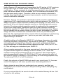
REQUIRED TOOLS
• Soldering Iron: Ramsey #RTS06
• Thin Rosin Core Solder: Ramsey #RTS12
• Needle Nose Pliers: Ramsey #RTS05
• Small Diagonal Cutters: Ramsey #RTS04
<OR> Complete Soldering Tool Set: (Radio Shack
RS64-2801)
TOTAL SOLDER POINTS
232
ESTIMATED ASSEMBLY
TIME
Beginner .............. 6.8 hrs
Intermediate ........ 3.9 hrs
Advanced ............ 2.9 hrs
ADDITIONAL SUGGESTED ITEMS
Soldering Iron Holder/Cleaner: (RS64-2078)
Holder for PC Board/Parts: Ramsey #RTS13
Desoldering Braid: Ramsey #RTS08
Digital Multimeter: Ramsey #M133
•
•
•
•
Price: $5.00
Ramsey Publication No. FR6
Assembly and Instruction manual for:
RAMSEY MODEL NO. FR6 6 METER FM RECEIVER KIT
R6 • 24