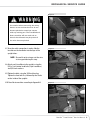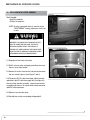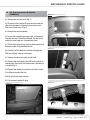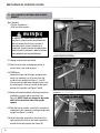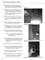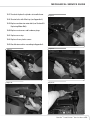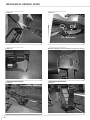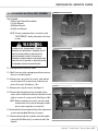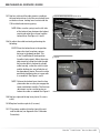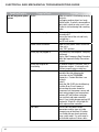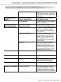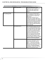
1
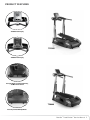
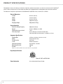
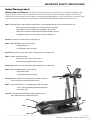
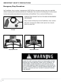
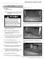
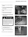
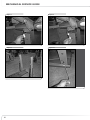
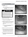
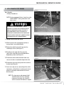
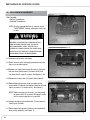
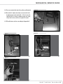
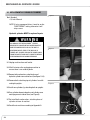
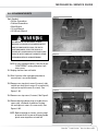
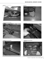
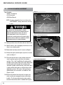
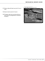
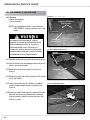
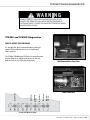
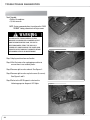
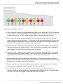
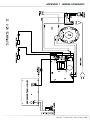
Service Manual
TC5300
• TC6000
P/N: 001-6890 Rev B (06/2007)
7! 2 . ) . '
$!.'%2
!4 4 % . 4 ) / .
For detailed instructions and information on assembly and use
for THE Bowflex® treadclimber®, model tc5300 and tc6000, fitness
machine refer to the assembly and owner’s manual.
)--%$)!4%!#4)/.2%15)2%$
#!54)/.
Table of contents
Product Features --------------------------------------------------------- 1
Product Specifications -------------------------------------------------- 2
Important Safety Precautions ------------------------------------------- 3
Mechanical Service Guide
1.0 Replacement of AC Inlet -------------------------------------- 7
2.0 Replacement of Console with Handlebars ------------------ 8
3.0 Replacement of Upper Console ------------------------------ 10
4.0 ROC Cable Replacement Instructions (TC6000 only) --------11
5.0 Replacement of Internal Wire in Right Upright ------------- 12
6.0 Replacement of Speed Sensor ------------------------------- 15
7.0 Replacement of Step Sensor --------------------------------- 17
8.0 Replacement of Motor Belt ----------------------------------- 18
9.0 Replacement of Hydraulic Cylinders -------------------------20
10.0 Replacement of Belts -----------------------------------------21
11.0 Replacement of Virtual Pivot Assembly -------------------- 25
12.0 Locking Mechanism Adjustment ---------------------------- 28
13.0 Replacement of Lock-out Lever ----------------------------- 30
Electrical and Mechanical Troubleshooting Guide ---------------- 32
TC5300 and TC6000 Diagnostics ---------------------------------------39
Appendix 1 - Wiring Schematic -------------------------------------- 43
Appendix 2 - Walking Belt Adjustment ------------------------------44
Appendix 3 - Calibration Procedures -------------------------------- 45
Appendix 4 - Walking Belt and Deck Lubrication ----------------- 46
Important Contact Numbers ------------------------------------------- 47
Bowflex® TreadClimber® Service Manual
Product features
TC5300 Console Display
TC5300
TC6000 Console Display
Transport Handles, Incoming Power Plug,
and Main Power Switch
TC6000
Rear Step and Rear Moving Wheels
Bowflex® TreadClimber ® Service Manual Product specifications
Throughout this manual, all references to the left or right side, and to the front or back, are made as if you were on the TreadClimber®
fitness machine, ready to exercise. For example, the power cord is plugged into the incoming power plug at the front of the base.
The dimensions and general specifications for the Bowflex® TreadClimber® fitness machine are as follows:
Physical Dimensions
66 inches (168 cm)
Length
Width
33 inches (84 cm)
Height
62 inches (157 cm)
Weight
350 pounds (147 kg)
Shipping Weight
393 pounds (178 kg)
System Capacities
300 pounds (136 kgs)
Maximum Weight Capacity
Speed
0.5 to 4.5 MPH (0.8 to 7.2 KPH)
Workout Resistance Levels
1 to 12
Warranty LengthSee the Warranty section for full information.
International Warranty information is included as an insert.
Component Specifications
Walking Belt
Motor
Treadle Incline
Frame
Operational Voltage
Operational Current
Breaker
8.5 inches x 44 inches (21.6 cm x 112 cm)
0.5 hp continuous duty
10% Grade
Powder-coated steel
95 to 130 VAC 50 - 60 Hz
10A Max
12A
Always use a 15A circuit with no loads. A short extension cord is permissible.
Regulatory Certifications
Patent Information
Meets UL 1647 and CSA 20.68. U.S. and International Patents Pending
Important safety precautions
Save These Instructions
7! 2 . ) . '
The following definitions apply to the word “Warning”
found throughout this manual:
7! 2 . ) . '
Used to call attention to
POTENTIAL hazards that could
result in personal injury or loss
of life.
Failure to follow these precautions can cause
damage to the Bowflex® TreadClimber® fitness
machine, serious injury to users and bystanders,
and can also compromise the effectiveness of your
exercise program.
$!.'%2
READ ALL INSTRUCTIONS BEFORE USING THE MACHINE.
$!.'%2
4 4 understand
% . 4 ) /and
. carefully follow all warnings, instructions, and procedures on the Bowflex® TreadClimber® fitness
1.!Read,
machine, and in the Assembly Guide and Owner’s Manual before using the TreadClimber® fitness machine. Pay particular
attention to and test the Emergency Stop Procedures on Page 5 before use.
!4 4 % . 4 ) / .
)--%$)!4%!#4)/.2%15)2%$
2. CONSULT YOUR PHYSICIAN BEFORE STARTING ANY EXERCISE PROGRAM. Only your physician can determine the exercise
program that is appropriate for your particular age and condition. If you have not been exercising, are pregnant, have a heart
condition, or any physical limitation, failure to consult your physician before engaging in physical exercise, such as using the
Bowflex® TreadClimber® fitness machine, could result in serious injury or death. If while using the Bowflex® TreadClimber®
fitness machine you have any pain or tightness in your chest, an irregular heart beat, shortness of breath, feel faint, light-headed
or dizzy, have any pain or discomfort, STOP and consult your physician immediately.
#!54)/.
3. Parents and others in charge of children should be aware that children, because of their natural play instinct and fondness for
experimenting, may be tempted towards situations and behavior for which the equipment is not intended, with resulting damage
to the equipment and injury to the children or others. Children’s access to the equipment should therefore be controlled, and
they should be instructed about the potential for personal injury and damage if they play with the equipment.
)--%$)!4%!#4)/.2%15)2%$
4. Inspect the TreadClimber® fitness machine for damaged, broken, worn, or loose components and then correct, replace, or
tighten prior to use. The fitness machine can only be safely used when it is regularly inspected for damage or wear. Inoperable
components should be replaced immediately or the equipment taken out of use until it is repaired.
#!54)/.
5. Be careful when mounting or dismounting the TreadClimber fitness machine. Do not stand on the Plastic Frame Covers or Drive
Covers but always step directly onto the Side Foot Support Platforms. Never step onto the treadles at a high belt speed. Start
your workout slowly and gradually increase to your desired workout speed.
®
6. The maximum speed of the TreadClimber® fitness machine is 4.5 MPH (7.2 KPH). Do not attempt to run on the TreadClimber®
fitness machine, but keep your highest speed at a brisk walk.
7. Do not wear any loose or dangling clothing, or jewelry while using the Bowflex® TreadClimber® fitness machine. Always keep
your hands, feet, clothing, etc. clear from beneath the treadles and from all moving parts. Never use your TreadClimber® fitness
machine with the Plastic Drive Covers or Frame Covers removed.
8. Always wear rubber-soled athletic shoes on the TreadClimber® fitness machine. Never use the TreadClimber® fitness machine
barefooted or wearing only socks.
9. Keep your foot centered on each treadle—do not allow your feet to cross in front of your body as you increase speeds.
10. Keep your hands on the support handlebars and stand as close to the front of the fitness machine as is comfortable in order to
remain in balance on the treadles.
11. Never convert from or into treadmill mode while the belts are in motion, or the machine is powered up. Turn off power, unplug
cord from wall outlet, line up the treadles, and then lock or release the treadle locking lever.
Bowflex® TreadClimber ® Service Manual Important safety precautions
12. Never adjust the Hydraulic Cylinder Workout Settings while belts are in motion. Step completely off of the TreadClimber® fitness
machine, stop the belts, and turn the power off prior to adjusting.
13. Maximum user weight for the Bowflex® TreadClimber® fitness machine is 300 pounds (136 kgs). For your safety, do not use or
allow others to use the Bowflex® TreadClimber® fitness machine if they weigh in excess of 300 pounds (136 kgs).
14. Make certain that observers stand clear of the Bowflex® TreadClimber® fitness machine when it is in use. Extra care must be
taken when disabled persons or pets are nearby.
15. Never allow children to use the Bowflex® TreadClimber® fitness machine unsupervised. To do so could result in injury. Before
children are allowed to use the equipment, their mental and physical development should be taken into account through
consultation with their doctor, who must approve any exercise program before a child attempts it. Children should be controlled
and instructed on the correct use of the equipment.
16. This equipment is under no circumstance suitable as a children’s toy.
17. For safety and security, when the TreadClimber® fitness machine is not in use, always lock the treadles and remove the Safety
Key.
18. Locate the TreadClimber® fitness machine on a clean, hard, level surface, free from debris, or other objects that may hamper
your ability to move freely. Always use a rubber mat beneath the TreadClimber® fitness machine if used on a carpeted area, to
ground it, to prevent static electricity discharge and to protect your flooring. Allow at least 19 inches (0.5 meters) on each side
of the machine and 79 inches (2 meters) in the rear of the machine for dismount.
19. Do not use your TreadClimber® fitness machine outdoors, on dirt floors, in a carpeted area or in any damp or wet location.
20. Keep the surface of the TreadClimber® fitness machine dry and free from dust or moisture.
21. Use only parts, attachments or accessories that are provided with the TreadClimber® fitness machine.
22. Always connect the power cord to a circuit capable of handling 10 amperes with no other loads. Keep all cords away from
heated surfaces.
23. Always unplug the power cord from the fitness machine and wall outlet before removing or installing parts to avoid the risk of
electrocution, shock or mechanical injury.
24. Position the power cord alongside the Bowflex® TreadClimber® fitness machine, out of your way when you dismount the
machine. Take care to avoid stepping on the power plug. Check cord and plug placement before beginning your workout.
25. Always be gentle when plugging in and unplugging the power cord from the machine base.
26. Never use the power cord if it has a damaged cord or plug, has been immersed in water, or is not working properly. Contact a
TreadClimber® Representative to arrange for replacement of a damaged cord.
27. Never drop or insert any object into any opening on the machine.
28. Do not operate where aerosol (spray) products are being used.
29. Do NOT attempt to move the TreadClimber® fitness machine without help, or from the rear of the unit. Doing so could cause
injury to you or damage the machine.
30. The TreadClimber® fitness machine is intended for individual consumer use only, and is not meant for use by institutions.
31. The warning labels affixed to the TreadClimber® fitness machine contain important information about your safety. Always
read and follow the Warning and Safety labels. Do not remove these labels. If at any time the warning labels become loose,
unreadable or dislodged, replacements are available by calling a Nautilus Representative.
32. Keep hands away from the Walking Belt and Deck unless specifically servicing the TreadClimber® fitness machine. Hands and
fingers may become caught in the moving belt or between the treadles.
Important safety precautions
Safety Warning Labels
BEFORE USING YOUR PRODUCT: The following safety warnings are located in site specific areas on the Bowflex® TreadClimber® fitness
machine. All locations are given as if you were standing on the fitness machine ready to exercise. Please read all safety precautions and warning
information prior to using your product. Be sure to replace any warning label if damaged, illegible, or missing. If you do not have, or cannot find, or need to replace a warning label or product Owner’s Manual please call 1-800-NAUTILUS (800-628-8458) to obtain a new label or new manual.
Label 1:”Warning: Obtain, read and understand the owner’s manual provided with this fitness equipment prior to use.
Misuse or abuse of this equipment may lead to serious injury or death.
Keep children away. This equipment is intended for adult use only.
Replace this or any other warning label if damaged, illegible or missing.
Intended for consumer use only, not for commercial application. “
Location: Left side of the console on the inside of the tray.
Label 2: “Warning: Moving part can crush and cut.
Keep guard in place.
Lock out power before servicing.”
Location: Beneath the rear step cover on the left side of the base assembly frame.
Label 3: “Danger: Hazardous voltage.
Contact will cause electric shock or burns.
Turn off and lock out power before servicing.
Location: Beneath the rear step cover on the right side of the base assembly frame.
Label 1
Label 4: “Warning: Moving parts can crush and cut.
Keep guard in place.
Lock out power before servicing.”
Location: At the rear of the fitness machine on the left outer side of the
base frame beneath the left drive plastic cover.
Label 5: “Warning: W hen Lever is in TreadClimber position test that the
Lever is correctly locked by the hook by pulling the
Lever to the right.”
Location: To the right side of the treadle locking mechanism on the
top of the base frame assembly plastic cover.
Label 4
Label 5
Label 2
Label 3
Bowflex® TreadClimber ® Service Manual Important safety precautions
Emergency Stop Procedures
Your TreadClimber ® fitness machine is equipped with a SAFETY KEY that can protect you from serious injury and inhibit
children from playing with and/or being injured on the TreadClimber ® fitness machine. If the Safety Key is not fully inserted
into the safety keyhole, located below the console display, the TreadClimber ® fitness machine will NOT power up.
Always ATTACH the safety key clip to your clothing during
your workout.
Always remove the Safety Key from the TreadClimber ® fitness machine
when not in use to prevent children or other persons from using the
machine unsupervised.
Safety Key
TC6000
TC5300
Safety Keyhole Location
Safety Keyhole Location
7! 2 . ) . '
REMOVE THE SAFETY KEY WHILE USING THE TREADCLIMBER® fitness
machine ONLY IN AN EMERGENCY. WHEN THE KEY IS REMOVED, THE
TREADCLIMBER® fitness MACHINE WILL STOP INSTANTLY, WHICH
COULD CAUSE SOMEBODY USING THE MACHINE TO LOSE BALANCE OR
FALL. This feature is meant to prevent serious harm and, used
properly, is an excellent way to protect your safety during
your workout.
$!.'%2
Mechanical Service guide
1.0 - REPLACEMENT OF AC INLET
Tools Needed:
• Phillips Screwdriver
Figure 1:
NOTE: If using a powered driver, it must be on the
“LOW TORQUE” setting, otherwise it will
strip screws.
7! 2 . ) . '
AS LONG AS THE TREADCLIMBER® FITNESS
MACHINE IS PLUGGED INTO A POWERED OUTLET
AND THE POWER SWITCH IS ON, THE UNIT IS
RECEIVING POWER, EVEN IF THE DISPLAY IS
TURNED OFF. ALWAYS UNPLUG THE POWER CORD
FROM THE OUTLET AND WAIT 5-MINUTES BEFORE
PERFORMING REPAIRS OR MAINTENANCE.
Front Base Plastic Cover
$!.'%2
Figure 2:
1-1 Unplug machine from wall outlet and remove AC
plug from front of machine.
!4 4 % . 4 ) / .
1-2 Wait 5-minutes after unplugging machine
to ensure there is no residual power before
performing replacement.
1-3 Remove front base plastic cover (4 screws). Make
sure locking mechanism latch is unlatched from
the front faceplate (see Figure 1 and 2).
)--%$)!4%!#4)/.2%15)2%$
Front Faceplate
1-4 Unscrew front faceplate (3 screws).
#!54)/.
1-5 C
arefully, pull faceplate towards you so that you
can see all three wires (see Figure 3).
Figure 3:
1-6 Remove AC inlet from wires and remove old inlet
from faceplate and replace with new one.
1-7 Insert wires into new inlet making sure
connections are correct (from front of plate: white
- top left, black - top right, green - bottom).
1-8 Replace faceplate and front plastic.
1-9 Recalibrate machine according to Appendix 3.
Bowflex® TreadClimber ® Service Manual Mechanical Service guide
2.0 - REPLACEMENT OF CONSOLE WITH HANDLEBARS
Tools Needed:
• Phillips Screwdriver
• 1/2 inch wrench
• 3/16 inch Allen wrench
Figure 1:
NOTE: If using a powered driver, it must be on the “LOW
TORQUE” setting, otherwise it will strip screws.
7! 2 . ) . '
AS LONG AS THE TREADCLIMBER® FITNESS
MACHINE IS PLUGGED INTO A POWERED OUTLET
AND THE POWER SWITCH IS ON, THE UNIT IS
RECEIVING POWER, EVEN IF THE DISPLAY IS
TURNED OFF. ALWAYS UNPLUG THE POWER CORD
FROM THE OUTLET AND WAIT 5-MINUTES BEFORE
PERFORMING REPAIRS OR MAINTENANCE.
$!.'%2
Figure 2: Upright Plastic Cover Removed
2-1 Unplug machine from outlet.
!4 4 % . 4 ) / .
2-2 W
ait 5-minutes after unplugging machine to ensure
there is no residual power.
2-3 T C5300 only: Remove the right and left upper upright plastics by
removing 2 small screws from the inside of each
upright (see Figure 1 & 2).
)--%$)!4%!#4)/.2%15)2%$
2-4 R
emove 4 button head bolts attaching console to
handlebars on both sides of machine (see Figure 3
& 4). NOTE: 3 bolts are located on the inside and 1
bolt is on the front side of the upright support.
#!54)/.
2-5 W
ith the help of another, carefully lift console out
and detach cable connector running through right
upright (see Figure 5 and 6).
2-6 A
ttach cable connector from new console to the
cable connector from the right upright.
Figure 3:
1 Bolt on front of Upright Support
3 Bolts on inside of Upright Support
Mechanical Service guide
Figure 4:
7! 2 . ) . '
Use caution when connecting the wiring
harness to ensure that the wires do not
become pinched or come into contact
with any moving part. The TreadClimber®
$!.'%2
fitness machine will not work and an
electric shock hazard may be present if
the wires become pinched.
2-7 O
nce the cable connection is made, slide the
brackets on the handlebar into the tops of the
upright tubes.
Figure 5:
!4 4 % . 4 ) / .
NOTE: Be careful not to crimp or cut the wire at at any point during this step.
2-8 A
ttach each handlebar to the uprights using the
5/16 x 1 inch button head bolts (4 per handlebar)
and 5/16 inch washers.
)--%$)!4%!#4)/.2%15)2%$
2-9 T ighten the bolts using the 3/16 inch hex key.
Tighten the front bolt first, followed by the 3 bolts
on the inside of the uprights.
#!54)/.
2-10 Recalibrate machine according to Appendix 3.
Figure 6:
Bowflex® TreadClimber ® Service Manual Mechanical Service guide
3.0 - REPLACEMENT OF UPPER CONSOLE
Figure 1:
Tools Needed:
• Small Screwdriver
• Phillips Screwdriver
NOTE: If using a powered driver, it must be on the
“LOW TORQUE” setting, otherwise it will strip
screws.
7! 2 . ) . '
AS LONG AS THE TREADCLIMBER® FITNESS
MACHINE IS PLUGGED INTO A POWERED OUTLET
AND THE POWER SWITCH IS ON, THE UNIT IS
RECEIVING POWER, EVEN IF THE DISPLAY IS
TURNED OFF. ALWAYS UNPLUG THE POWER CORD
FROM THE OUTLET AND WAIT 5-MINUTES BEFORE
PERFORMING REPAIRS OR MAINTENANCE.
$!.'%2
3-1 Unplug machine from wall outlet.
!4 4 % . 4 ) / .
3-2 W
ait 5-minutes after unplugging machine to ensure
there is no residual power.
3-3 R
emove 4 screws from back of console and remove
the rear console plastic (see Figure 1 and 2).
)--%$)!4%!#4)/.2%15)2%$
3-4 Disconnect R.O.C. cable from upper right of console
and white 8-pin I/O cable from upper left. (see Figure 2).
Unscrew front console assembly. remove front console
assembly and replace. Re-attach white cable connector
and ROC cable connector.
#!54)/.
3-5 Replace rear console cover.
3-6 Recalibrate machine according to Appendix 3.
10
Figure 2: Console Back Removed
Mechanical Service guide
4.0 - ROC Cable Replacement Instructions
(TC6000 Only)
Figure 2:
4-1 Remove the console back. (Fig. 1)
4-2 Disconnect the remote HR wire from the lower left
side of the printed circuit board (viewed from front).
Red, black, white wires. (Fig. 2)
4-3 Remove the console bottom.
4-4 Locate the connector on upper right, and unplug it
from the console Printed Circuit Board. Cut the zip ties
and let the wire hang free. (viewed from front) .
4-5 Tie the black plug of new cable to the brown plug of
defective cable using included wire tie.
Figure 3:
4-6 Carefully pull the defective cable out through the
ROC hole,and pull new wire into place.
4-7 Remove the defective cable and discard.
4-8 Connect the black plug to the ROC and re-attach to
control plate. Be careful not to pinch new cable during
assembly.(Fig. 4)
4-9 Connect the brown plug to the back of the Printed
Circuit Board and test the unit.
4-10 Re-attach the lower console.
4-11 Re-connect remote HR plug.
Figure 1:
Figure 4:
Bowflex® TreadClimber ® Service Manual 11
Mechanical Service guide
5.0 - REPLACEMENT OF INTERNAL WIRE IN RIGHT
UPRIGHT
Figure 1:
Tools Needed:
• Phillips Screwdriver
• 3/16 inch Allen wrench
7! 2 . ) . '
AS LONG AS THE TREADCLIMBER® FITNESS
MACHINE IS PLUGGED INTO A POWERED OUTLET
AND THE POWER SWITCH IS ON, THE UNIT IS
RECEIVING POWER, EVEN IF THE DISPLAY IS
TURNED OFF. ALWAYS UNPLUG THE POWER CORD
FROM THE OUTLET AND WAIT 5-MINUTES BEFORE
PERFORMING REPAIRS OR MAINTENANCE.
$!.'%2
Figure 2: Upright cover removed.
5-1 Unplug machine from wall outlet.
!4 4 % . 4 ) / .
5-2 W
ait 5-minutes after unplugging machine to
ensure there is no residual power.
5-3 T C5300 only: Remove the right and left upper upright plastic
covers by removing 2 small screws from the
inside of each upright (see Figure 1, 2 and 3).
Also remove the right lower upright plastic cover
by removing the 2 screws from the inside lower
portion of the upright (see Figure 5 and 6).
)--%$)!4%!#4)/.2%15)2%$
#!54)/.
5-4 R
emove 4 button head bolts attaching console to
handlebars on both sides of machine (see
Figure 4). NOTE: 3 bolts are located on the inside
and 1 bolt is on the front side of the upright
support.
5-5 W
ith the help of another, carefully lift console out
and detach cable connector running through right
upright (see Figure 7, 8 and 9).
5-6 D
etach the cable connector at the base of the
right upright after it exists the lower hole on the
outside of the right upright (see Figure 10).
12
Figure 3:
1 Bolt on front of Upright Support
3 Bolts on inside of Upright Support
Mechanical Service guide
5-7 R
emove wire from right upright by pulling from
the bottom.
Figure 4:
5-8 T hread new wire through right upright. Making
sure the cable exits through the lower slotted
hole in the upright.
5-9 R
e-attach cable connector at base of right
upright.
5-10 A
ttach cable connector from console to the
cable connector from the right upright.
5-11 W
ith the help of another person, lift the console
back onto both uprights, ensuring that junction
covers are in place.
Figure 5:
7! 2 . ) . '
Use caution when connecting the wiring
harness to ensure that the wires do not
become pinched or come into contact
with any moving part. The TreadClimber®
$!.'%2
fitness machine will not work and an
electric shock hazard may be present if
the wires become pinched.
Figure 6:
5-12 R
e-attach both uprights to console using 4
button head bolts on each side.
!4 4 % . 4 ) / .
5-13 R
e-attach the right and left upper upright
plastics as well as the right lower upright plastic
cover.
5-14 R
ecalibrate machine according to Appendix 3.
)--%$)!4%!#4)/.2%15)2%$
Bowflex® TreadClimber ® Service Manual 13
Mechanical Service guide
14
Figure 7:
Figure 8:
Figure 9:
Figure 10:
Mechanical Service guide
6.0 - REPLACEMENT OF SPEED SENSOR
Figure 1:
Tools Needed:
• Phillips Screwdriver
NOTE: If using a powered driver, it must be on the
“LOW TORQUE” setting, otherwise it will
strip screws.
6-1
7! 2 . ) . '
AS LONG AS THE TREADCLIMBER® FITNESS
MACHINE IS PLUGGED INTO A POWERED OUTLET
AND THE POWER SWITCH IS ON, THE UNIT IS
RECEIVING POWER, EVEN IF THE DISPLAY IS
TURNED OFF. ALWAYS UNPLUG THE POWER CORD
FROM THE OUTLET AND WAIT 5-MINUTES BEFORE
PERFORMING REPAIRS OR MAINTENANCE.
$!.'%2
Figure 2:
Unplug machine from wall outlet.
!4 4 % . 4 ) / .
6-2 W
ait 5-minutes after unplugging machine to
ensure there is no residual power.
6-3 R
emove rear step plastic cover (8 screws), right
and left rear base plastic covers (3 screws each),
and rear base plastic cover (5 screws). See
Figures 1 & 2.
)--%$)!4%!#4)/.2%15)2%$
NOTE: O
ne screw each on the right and left side
base plastic is behind the decal
(see Figure 3).
#!54)/.
6-4 R
emove rear step cover (4 screws). See Figure 4.
Figure 3:
One screw behind decal.
6-5 L ooking at machine from left side, locate black
wire connected to hole in left rear drive bracket
(wire is approximately 3 3/4 inches long and is
located below left rear roller) see Figure 5 & 6.
6-6 D
isconnect white cable connector from speed
sensor wire that is attached to long black wire
(see Figure 6).
Bowflex® TreadClimber ® Service Manual 15
Mechanical Service guide
6-7 D
isconnect speed sensor plug from left treadle
pivot bracket.
Figure 4:
6-8 I nsert new speed sensor, connecting white cable
connectors, and making sure not to push sensor
plug too far through connector hole in left treadle
pivot bracket.
NOTE: T he speed sensor and grommet (red)
should be 1/8 inch or less from the magnet
on the pulley, but shouldn’t come into
contact with pulley or magnet
(see Figure 7).
6-9 Replace Rear Step.
Figure 5:
6-10 R
eplace right and left rear base plastic cover,
rear step plastic, rear base plastic cover, and side
plastic decals.
6-11 Recalibrate machine according to Appendix 3.
Figure 6:
16
Figure 7:
Mechanical Service guide
7.0 - REPLACEMENT OF STEP SENSOR
Figure 1:
Tools Needed:
• Phillips Screwdriver
NOTE: If using a powered driver, it must be on the
“LOW TORQUE” setting, otherwise it will
strip screws.
7! 2 . ) . '
AS LONG AS THE TREADCLIMBER® FITNESS
MACHINE IS PLUGGED INTO A POWERED OUTLET
AND THE POWER SWITCH IS ON, THE UNIT IS
RECEIVING POWER, EVEN IF THE DISPLAY IS
TURNED OFF. ALWAYS UNPLUG THE POWER CORD
FROM THE OUTLET AND WAIT 5-MINUTES BEFORE
PERFORMING REPAIRS OR MAINTENANCE.
$!.'%2
Top Base Plastic Cover
Figure 2:
7-1 Unplug machine from wall outlet.
7-2 W
ait 5-minutes after unplugging machine to
ensure there is no residual power.
!4 4 % . 4 ) / .
7-3 R
emove the right base plastic top cover by
removing 3 screws (see Figure 1).
Step Sensor
7-4 S
tanding on the right side of the unit, the
step sensor should be accessible behind the
dependency teeter (see Figure 2).
)--%$)!4%!#4)/.2%15)2%$
#!54)/.
7-5 D
isconnect white cable connector from step
sensor wire that is attached to long black wire.
Figure 3:
7-6 D
isconnect step sensor plug from left rear drive
bracket (see Figure 3).
7-7 I nsert new step sensor, connecting white cable
connectors, and making sure not to push sensor
plug to far through connector hole in left rear
drive bracket.
Step Sensor Plug
NOTE: The step sensor and grommet (red)
should be 1/8 inch or less from the
magnet on the teeter, but shouldn’t
come in contact with teeter or magnet.
Bowflex® TreadClimber ® Service Manual 17
Mechanical Service guide
8.0 - REPLACEMENT OF MOTOR BELT
Figure 1:
Tools Needed:
• Phillips Screwdriver
• Flathead Screwdriver
NOTE: If using a powered driver, it must be on the
“LOW TORQUE” setting, otherwise it will strip
screws.
7! 2 . ) . '
AS LONG AS THE TREADCLIMBER® FITNESS
MACHINE IS PLUGGED INTO A POWERED OUTLET
AND THE POWER SWITCH IS ON, THE UNIT IS
RECEIVING POWER, EVEN IF THE DISPLAY IS
TURNED OFF. ALWAYS UNPLUG THE POWER CORD
FROM THE OUTLET AND WAIT 5-MINUTES BEFORE
PERFORMING REPAIRS OR MAINTENANCE.
$!.'%2
Figure 2: Rear Plastic Covers removed.
8-1 Unplug machine from wall outlet.
!4 4 % . 4 ) / .
8-2 W
ait 5-minutes after unplugging machine to ensure
there is no residual power.
8-3 Remove rear step plastic cover (8 screws), right and
left rear base plastic covers (3 screws each), and
rear base plastic cover (5 screws). See Figures 1 & 2.
)--%$)!4%!#4)/.2%15)2%$
8-4 Remove rear step cover (4 screws). See Figure 3.
8-5 R
emove black hardware plugs in treadle plastic
covers with a Flathead screwdriver. Remove left and
right cast covers (2 screws each). See Figure 4.
#!54)/.
NOTE: Before removing cast covers, you may need
to loosen the first screw on the upper treadle
plastic cover to get the cast cover off.
8-6 L oosen the motor tension bolt with 1/2 inch wrench
(see Figures 5 and 6).
8-7 R
otate motor belt counter-clockwise easing belt off
drive pulley gradually (see Figure 7).
18
Figure 3: Rear Step removed.
Mechanical Service guide
8-8 Ease new motor belt onto drive pulley and flywheel.
Figure 4:
8-9 O
nce belt is tightly attached, re-tension the belt
by tightening tension bolt with a 1/2 inch wrench,
replace left cast cover, hardware plug, rear step,
rear plastic cover, and rear step plastic cover.
8-10 Recalibrate machine according to Appendix 3.
Figure 6:
Figure 5:
Motor Pan
Bolt
Motor Pan Bolt
Figure 7:
Drive Pulley
Bowflex® TreadClimber ® Service Manual 19
Mechanical Service guide
9.0 - REPLACEMENT OF HYDRAULIC CYLINDERS
Tools Needed:
• 1/2 inch Wrench
Figure 1:
NOTE: If using a powered driver, it must be on the
“LOW TORQUE” setting, otherwise it will
strip screws.
Hydraulic cylinders MUST be replaced in pairs.
7! 2 . ) . '
AS LONG AS THE TREADCLIMBER® FITNESS
MACHINE IS PLUGGED INTO A POWERED OUTLET
AND THE POWER SWITCH IS ON, THE UNIT IS
RECEIVING POWER, EVEN IF THE DISPLAY IS
TURNED OFF. ALWAYS UNPLUG THE POWER CORD
FROM THE OUTLET AND WAIT 5-MINUTES BEFORE
PERFORMING REPAIRS OR MAINTENANCE.
Figure 2:
$!.'%2
9-1 U
nplug machine from wall outlet.
!4 4 % . 4 ) / .
9-2 W
ait 5-minutes after unplugging machine to
ensure there is no residual power.
9-3 Remove bolts and washers attaching base of
hydraulic cylinders to machine base (see Figure 1 & 2).
)--%$)!4%!#4)/.2%15)2%$
9-4 R
emove bolts attaching top of cylinders from left
and right uprights.
Figure 3:
#!54)/.
9-5 Install new cylinders, by attaching bolts to uprights.
9-6 Ease cylinders down to loop base of cylinders over
metal peg on each side of base (see Figure 3).
9-7 R
e-install bolts and washers, attaching base of
cylinders to base of machine.
9-8 Recalibrate machine according to Appendix 3.
20
Metal Peg
Mechanical Service guide
10.0 - REPLACEMENT OF BELTS
Tools Needed:
• Phillips Screwdriver
• Flathead Screwdriver
• Allen Wrench
• 1/2 inch Wrench
• (2) 9/16 inch Wrench
Figure 1:
7! 2 . ) . '
AS LONG AS THE TREADCLIMBER® FITNESS
MACHINE IS PLUGGED INTO A POWERED OUTLET
AND THE POWER SWITCH IS ON, THE UNIT IS
RECEIVING POWER, EVEN IF THE DISPLAY IS
TURNED OFF. ALWAYS UNPLUG THE POWER CORD
FROM THE OUTLET AND WAIT 5-MINUTES BEFORE
PERFORMING REPAIRS OR MAINTENANCE.
$!.'%2
Figure 2:
NOTE: If using a powered driver, it must be on the
“LOW TORQUE” setting, otherwise it will
strip screws.
10-1 Unplug machine from wall outlet.
!4 4 % . 4 ) / .
10-2 Wait 5-minutes after unplugging machine to
ensure there is no residual power.
)--%$)!4%!#4)/.2%15)2%$
10-3 R
emove rear step plastic cover (8 screws), right
and left rear base plastic covers (3 screws each),
and rear base plastic cover (5 screws). See
Figures 1 & 2.
#!54)/.
Figure 3:
10-4 Remove rear step cover (4 screws). See Figure 3.
10-5 R
emove black hardware plugs in treadle plastic
covers with a Flathead screwdriver. Remove
left and right cast covers (2 screws each). See
Figures 4 & 5.
NOTE: Before removing cast covers, you may need
to loosen the first screw on the upper treadle
plastic cover to get the cast cover off.
Bowflex® TreadClimber ® Service Manual 21
Mechanical Service guide
10-6 Ease poly-v belt off of the rear roller pulley.
Tensioning screw may need to be loosened (see
Section 9.0 Replacing Motor Belt). See Figure 6.
Figure 4:
10-7 R
emove the 4 front roller adjustment screws using
a 3/16 Allen Key (see Figure 7). Remove the 2
front rollers by loosening the 2 inside front roller
brackets using a 3/16 Allen Wrench and 1/2 inch
wrench (see Figures 8, 9, 10).
10-8 R
emove the rear roller with a 1/2 inch wrench (1
screw). Rear roller should slide out from belts after
release from mounting location (see Figure 11
&12).
10-9 R
emove lower hydraulic cylinder from the treadle
frame with Allen key (1 screw each side).
Figure 5:
10-10 S
tanding on the left side of the machine detach
the treadle/teeter cross tube by removing 2 bolts
with two 9/16 inch wrenches (see Figure 13).
10-11 R
otate left treadle back (pivoting about treadle
pivot bracket) until it rests on the rear step frame.
NOTE: Lay a rag down on the rear step frame to
protect treadle plastic from damage (see
Figure 14, 15 & 16).
10-12 T he old belt can be removed by pulling it over the
front roller bracket and cam follower bracket on
the inside of the treadle. Replace with new belt
(see Figure 17).
10-13 R
epeat Steps 10-9 to 10-11 on the right treadle.
10-14 R
un rear roller through belts (remembering to run
through poly-v belt as well) and re-mount the rear
roller. Attach with screw (see Figure 11).
10-15 R
eplace front rollers and front roller adjustment
screws (see Figures 7, 8 & 9).
10-16 R
otate treadles back one at a time (making sure
cam follower bracket seats on cam followers)
and re-attach teeter/treadle cross tubes.
22
Figure 6:
Mechanical Service guide
10-17 Re-attach hydraulic cylinders to treadle frame.
Figure 7:
10-18 Tension belts with Allen key (see Appendix 2).
10-19 R
eplace and tension motor belt (see Section 9.0
Replacing Motor Belt).
10-20 Replace cast covers and hardware plugs.
10-21 Replace rear step.
10-22 Replace 4 rear plastic covers.
10-23 Recalibrate machine according to Appendix 3.
Figure 8:
Figure 9:
Figure 10:
Figure 11:
Bowflex® TreadClimber ® Service Manual 23
Mechanical Service guide
Figure 12:
Figure 13:
Cross Member Bolts
24
Figure 14:
Figure 15: Damage caused to treadle by rear step if not covered.
Figure 16:
Figure 17:
Mechanical Service guide
11.0 - REPLACEMENT OF VIRTUAL PIVOT ASSEMBLY
Figure 1:
Tools Needed:
• Phillips and Flathead Screwdriver
• 1/2 inch Wrench
• 3/16 Allen Wrench
• (2) 9/16 inch Wrench
NOTE: If using a powered driver, it must be on the
“LOW TORQUE” setting, otherwise it will strip
screws.
7! 2 . ) . '
AS LONG AS THE TREADCLIMBER® FITNESS
MACHINE IS PLUGGED INTO A POWERED OUTLET
AND THE POWER SWITCH IS ON, THE UNIT IS
RECEIVING POWER, EVEN IF THE DISPLAY IS
TURNED OFF. ALWAYS UNPLUG THE POWER CORD
FROM THE OUTLET AND WAIT 5-MINUTES BEFORE
PERFORMING REPAIRS OR MAINTENANCE.
Figure 2:
$!.'%2
11-1 Unplug machine from wall outlet.
11-2 Wait 5-minutes after unplugging machine to ensure
there is no residual power.
!4 4 % . 4 ) / .
11-3 R
emove rear step plastic (8 screws), right and left
rear base plastic (3 screws each), and rear base
plastic (5 screws). See Figures 1 & 2.
)--%$)!4%!#4)/.2%15)2%$
Figure 3:
11-4 Remove rear step (4 screws). See Figure 3.
11-5 Remove black hardware plugs in treadle plastic
covers with a Flathead screwdriver. Remove left and
right cast covers (2 screws each). See Figures 4 & 5.
#!54)/.
NOTE: Before removing cast covers, you may need
to loosen the first screw on the upper treadle
plastic cover to get the cast cover off.
11-6 L oosen belts by loosening the front roller adjustment
screws with provided Allen key (4 screws).
11-7 R
emove lower hydraulic cylinders from the treadle
frame with 3/16 Allen key (1 screw each side). See
Figure 6.
Bowflex® TreadClimber ® Service Manual 25
Mechanical Service guide
11-8 S
tanding on the left side of the machine detach the
treadle/teeter cross tube by removing 2 bolts with two
9/16 inch wrenches (see Figure 7).
Figure 4:
11-9 P
lace a rag on the rear step frame to protect treadle
plastic from damage. Rotate left treadle back (pivoting
about treadle pivot bracket) until it rests on the rear
step frame (see Figure 8 & 9).
11-10 Repeat Steps 11-7 to 11-9 for the right treadle.
11-11 R
emove 4 screws with a 1/2 inch wrench from the
virtual pivot bracket. Replace old cam follower
bracket assembly with new assembly. Finger tighten
the 4 screws so that bracket can still be easily slid
back and forth in slotted holes (see Figure 10).
11-12 R
otate left treadle back, seating it on the new cam
followers and replace treadle teeter cross-member
with 2 bolts. Repeat on right treadle.
Figure 5:
11-13 P
lace 0.75 inch spacer between treadles at the inner
front roller brackets to space apart treadles (see
Figure 11).
11-14 T ension belts with 4 tensioning screws at the front
rollers with an Allen key.
11-15 P
ush the cam follower bracket as far forward as
possible with thumbs. Tighten 4 screws with a 9/16
inch wrench on the virtual pivot bracket. It is very
important to tighten the 2 rear screws first before
tightening the front 2 screws (see Figure 12).
11-16 R
emove spacer making sure treadles do not touch
each other. Force them together to make sure they
are secure.
11-17 Re-attach hydraulic cylinders to treadle frame.
11-18 Replace cast covers and hardware plugs.
11-19 Replace rear step.
11-20 Replace 4 rear plastic parts.
11-21 Recalibrate machine according to Appendix 3.
26
Figure 6:
Mechanical Service guide
Figure 7:
Figure 8:
Cross Member Bolts
Figure 9:
Figure 10:
Figure 11:
Figure 12:
Bowflex® TreadClimber ® Service Manual 27
Mechanical Service guide
12.0 - LOCKING MECHANISM ADJUSTMENT
Tools Needed:
• Phillips Screwdriver
• 1/2 inch wrench
• 3/16 Allen Wrench
Figure 1:
Right & Left Top Base
Plastic Covers
NOTE: If using a powered driver, it must be on the
“LOW TORQUE” setting, otherwise it will strip
screws.
7! 2 . ) . '
AS LONG AS THE TREADCLIMBER® FITNESS
MACHINE IS PLUGGED INTO A POWERED OUTLET
AND THE POWER SWITCH IS ON, THE UNIT IS
RECEIVING POWER, EVEN IF THE DISPLAY IS
TURNED OFF. ALWAYS UNPLUG THE POWER CORD
FROM THE OUTLET AND WAIT 5-MINUTES BEFORE
PERFORMING REPAIRS OR MAINTENANCE.
$!.'%2
Front Base
Plastic Cover
Figure 2: Unlock Treadles Position
Treadle Lockout Lever
12-1 Unplug machine from wall outlet and from front of unit.
12-2 Wait 5-minutes after unplugging machine to ensure
there is no residual power.
!4 4 % . 4 ) / .
12-3 Remove the front base plastic (4 screws) see Figure 1.
Faceplate
12-4 R
emove the right and left top base plastic (3 screws
each) see Figure 1.
)--%$)!4%!#4)/.2%15)2%$
12-5 P
lace the lockout lever in the position where the
front faceplate captures the lever in the down
position. This is the TreadClimber® mode position
(treadles freely rotate). Adjust the major adjustment
by pulling the cable through the junction plastic
and metal cylinder cable housing, so that the cable
is tight and the locking pins are pulled clear of the
dependency teeter. Secure the cable position by
tightening the set screw with a screwdriver. See
Figure 2 and 3.
Figure 3: Major Adjustment
#!54)/.
12-6 Release the lockout lever from the face plate and
make sure the pins engage the teeter and lockout
treadles. The fine tune adjustment can be used to
tension or loosen the cable as needed. See Figure 4.
28
Setscrew
Junction Plastic
Cable
Mechanical Service guide
Figure 4: Minor Adjustment & Lockout Level
12-7 R
eplace right and left top base plastic (3 screws
each).
Lockout Lever
12-8 Replace front base plastic (4 screws).
12-9 P
lug power cord back into the front of the unit
and recalibrate (see Appendix 3 for Calibration
Procedure).
Faceplate
Cable must run
through lockout
lever
Minor Adjustment
Bowflex® TreadClimber ® Service Manual 29
Mechanical Service guide
13.0 - REPLACEMENT OF LOCK-OUT LEVER
Tools Needed:
• Phillips Screwdriver
• 7/16 inch wrench
Figure 1:
Right & Left Top Base
Plastic Covers
NOTE: If using a powered driver, it must be on the
“LOW TORQUE” setting, otherwise it will strip
screws.
7! 2 . ) . '
AS LONG AS THE TREADCLIMBER® FITNESS
MACHINE IS PLUGGED INTO A POWERED OUTLET
AND THE POWER SWITCH IS ON, THE UNIT IS
RECEIVING POWER, EVEN IF THE DISPLAY IS
TURNED OFF. ALWAYS UNPLUG THE POWER CORD
FROM THE OUTLET AND WAIT 5-MINUTES BEFORE
PERFORMING REPAIRS OR MAINTENANCE.
$!.'%2
Front Base
Plastic Cover
Figure 2: Unlock Treadles Position
Treadle Lockout Lever
13-1 Unplug machine from wall outlet and from front of unit.
!4 4 % . 4 ) / .
13-2 W
ait 5-minutes after unplugging machine to ensure
there is no residual power.
13-3 R
emove the front base plastic (4 screws) see
Figure 1.
Faceplate
)--%$)!4%!#4)/.2%15)2%$
13-4 R
emove the right and left top base plastic (3 screws
each) see Figure 1.
13-5 L oosen the setscrew with a Phillips screwdriver
and pull cable through the plastic junction. See
Figure 3.
#!54)/.
13-6 R
emove the old lockout lever by removing 7/16 inch
bolt and retaining spring. Remove the cable and
fine adjustment assembly from the old lever. See
Figure 2, 4 and 5.
Figure 3: Major Adjustment
Setscrew
Junction Plastic
Cable
30
Mechanical Service guide
13-7 R
eplace cable and fine adjustment assembly on
the new lockout lever. Install the new lockout lever
on the base frame locking lever bracket with the
7/16 inch bolt and retaining spring.
NOTE: M
ake sure the spring is on the left side
of the lockout lever between the lockout
retaining bracket (base frame) and the
lockout lever. See Figure 2, 4 and 5.
Figure 4: Minor Adjustment & Lockout Level
Lockout Lever
Faceplate
Cable must run
through lockout
lever
13-8 R
e-adjust the cable tension by performing the
following: FIRST: Place the lockout lever in the position
where the front faceplate captures
the lever in the down position. This
is the TreadClimber® mode position
(treadles freely rotate). Adjust the major
adjustment by pulling the cable through
the junction plastic and metal cylinder
cable housing, so that the cable is tight
and the locking pins are pulled clear of
the dependency teeter. Secure the cable
position by tightening the set screw with
a screwdriver. See Figure 2 and 3.
Minor Adjustment
Figure 5:
7/16 inch bolt
NEXT: R
elease the lockout lever from the face
plate and make sure the pins engage the
teeter and lockout treadles. The fine tune
adjustment can be used to tension or
loosen the cable as needed. See Figure 4.
13-9 R
eplace right and left top base plastic (3 screws
each).
13-10 Replace front base plastic (4 screws).
13-11 P
lug power cord back into the front of the unit
and recalibrate (see Appendix 3 for Calibration
Procedure).
Bowflex® TreadClimber ® Service Manual 31
Electrical and Mechanical troubleshooting guide
Condition/Problem
Unit will not power up/turn
on/start
32
Things to Check
Solution
Outlet.
Make sure outlet is functioning correctly.
Verify this
by plugging another object (ex: lamp)
into the outlet. If outlet is connected to a
light switch, check to make sure it is on.
If outlet is not functioning find a working
outlet.
Power cord not plugged in.
Make sure the power cord is firmly
secured to A/C
inlet on the front of the unit and firmly
inserted into a
non-GFI wall socket.
Power switch turned off.
Make sure the power switch at the rear
of the unit is
in the “ON” position.
Safety key not plugged in.
Plug Safety Key into magnetic safety key
location on
display. (See Emergency Stop Procedure
within the Important Safety Precautions
section)
Safety key magnet not
functioning.
Try another magnet if available, such as
refrigerator magnet. If unit works with
different magnet replace safety key.
LED Diagnostic needed.
Access diagnostic LEDs on motor
controller board by following the
instructions in the TC5300/6000
Diagnostics. Caution: Machine is on.
Current is
active!!.
Check the B & G LEDs for the following:
If neither B nor G are lit power is
not reaching the motor controller.
Disconnect unit from power source and
check wiring integrity and connections
between A/C inlet (where cord plugs
in to machine) and motor controller
board. If any visible damage replace A/C
junction kit. If light G is lit but light B is
not lit replace motor controller
I/O Cables
If LEDs B & G are both lit check
connections and for signs of visible
damage to any of the three I/O calbes.
If no visible damage check continuity
using a multi-meter. If a multi-meter is
not available replace all three cables.
Electrical and Mechanical troubleshooting guide
Condition/Problem
Speed displayed is not
accurate.
Heart rate not displayed
while using chest strap.
Walking belt misalignment.
Things to Check
Solution
Console control board
If I/O cables are all functioning properly,
LEDs B & G are lit up, and machine still
will not power up replace upper console
control board
Display set to wrong unit of
measure. (English/Metric)
Change display units. (See Console
Display & Set Up section)
Out of calibration.
Re-calibrate machine. (See Calibration
Procedures, appendix 3)
Transmitter not making
good contact with skin.
Moisten skin contact area on the chest
strap. (See Heart Rate Monitoring section)
Electromagnetic interference.
Turn off any television, AM radio,
microwave, or computer within 6
feet (2 meters) of the TreadClimber®
fitness machine.
Chest strap transmitter.
Test chest strap with another HR
monitoring device such as HR watch,
machine at a gym. If transmitter has
good skin contact and still is not found
to be emitting HR signal replace chest
strap transmitter.
HR receiver.
If chest strap is known to work with
other devices and no sources of
interference are present, or if console
has been tested with a Pulse Simulator
and is not receiving the signal, replace
the following HR receiver and wire.
Machine Powered Up
See Troubleshooting step 1
Wire connection
Check connection at board and at controls
Wire
If connections good replace wire (see
Replacing ROC Cable instructions)
Controls
If problem persists replace ROC controls.
Tracking adjustment
If either of the walking belts seem to be
tracking excessively to one side or the
other adjust belt at front of each treadle
(see Walking Belt Adjustment, Appendix 2)
Bowflex® TreadClimber ® Service Manual 33
Electrical and Mechanical troubleshooting guide
Condition/Problem
Hesitation or belt slipping
when walking on unit.
34
Things to Check
Solution
Roller shaft bracket
If belt adjustments don’t correct
misalignment replace both belts and
either or both roller shaft bracket
depending on which belt(s) aren’t
aligning.
Belt tension
If belt hesitates or slips when walking
on unit it may be caused by either a
loose walking belt or a loose drive belt.
To determine the cause perform the
following test:
Stand beside TreadClimber® fitness
machine and set speed to 2 MPH. Step on
one treadle and attempt to stop movement.
If one belt stops but roller at rear and other
belt continue to turn walking belt tension
should be adjusted. If both belts stop but
motor is still turning the drive belt tension
should be adjusted.
Walking belt tension
Adjust walking belt tension at the front of
the unit using the provided hex wrench
on the exposed adjustment bolts located
on each side of each front roller. Tighten
(turn clockwise) each adjustment bolt
in full turn increments. Be sure to adjust
both bolts on each roller the same
amount as to not disrupt belt alignment.
After each adjustment, restart unit and
check to see if belt slippage has been
eliminated. Repeat if necessary. If slipping
feel persists after several adjustments,
stop and refer to drive belt checklist.
Drive belt.
Unplug power from unit. Wait 5-minutes
to ensure no residual power remains.
Remove rear base plastic cover to
expose “v” belt drive line and motor.
Tighten nut on the motor tension bolt
located on front side of motor in 1/2 turn
increments until drive belt slippage
is eliminated - DO NOT OVER TIGHTEN.
Reinstall rear base plastic cover
Electrical and Mechanical troubleshooting guide
Condition/Problem
Things to Check
Solution
Knocking / squeaking noises Upper linkage bolts.
when unit is operating.
Unplug power from Unit. Wait 5-minutes
to ensure no residual power remains.
Located on the underneath side of each
treadle there are bolts, one per side, that
connect the treadles to the linkage arms.
Push right treadle down to access left
treadle and vice versa. Using a 9/16”
wrench and Allen key, make sure these
bolts are securely tightened.
Lower linkage bolts.
Unplug power cord from rear of unit.
Wait 5-minutes to ensure no residual
power remains. Push the right treadle all
the way down to access left teeter bolt.
You will see a linkage system near
the middle of the unit that ties the two
treadles together. On the left side of the
linkage pivot, you will see a bolt that
connects the linkage arms to the pivot.
Using a 9/16” wrench and an Allen
key, make sure that bolts are securely
tightened. Push the left treadle all the
way down and repeat for right side.
Locking pins
Check if treadle locking pins are releasing
fully in unlocked “TreadClimber®” mode.
If not, adjust cable length to allow pins to
fully retract.
Drive pulley and flywheel pulley.
Unplug power from Unit. Wait at least 5
minutes. Remove left side plastic drive
cover to expose “v” belt drive line.
Using a ½” wrench, tighten the bolt that
attaches the 4 ½” drive pulley to the drive
shaft while holding the drive rollers still.
Also, using a 5/32” hex wrench, tighten
the setscrew on the flywheel motor
pulley. Reinstall plastic drive cover.
Rear roller.
If knocking sound seems to be coming
directly from the rear roller, replace.
Hydraulic cylinder bolts.
Unplug power from Unit. Wait at least
5 minutes. Check and tighten both
upper and lower bolts that connect the
hydraulic cylinders to the unit.
Front rollers.
If knocking sound seems to be coming
directly from one or both of the front
rollers, remove and replace rollers.
Bowflex® TreadClimber ® Service Manual 35
Electrical and Mechanical troubleshooting guide
Condition/Problem
Belts stop turning and “err
LS” or “err OS” is displayed
Things to Check
Solution
Virtual pivot.
Access the virtual pivot by removing
the rear step plastic and rear step. The
virtual pivot will be under the rear roller
and has 2 brackets (one on each treadle,
which rolls on 4 cam followers (large
bearings). Make sure all 4 brackets are
rolling (turning) as the treadles pivot. If
knocking/squeaking is coming from the
virtual pivot or if any of the 4 cam
followers are not rolling the virtual pivot
(also referred to as “Bearing Roller Kit”)
should be replaced.
Treadle alignment
If treadles are not centered between the
uprights and are contacting one of the
uprights check if treadles are parallel.
If not adjust virtual pivot. If treadles
are parallel but are still contacting
an upright entire machine must be
replaced.
Calibration
Re-calibrate machine. (See Calibration
Procedures, appendix 3)
Speed sensor
1. Cycle power off and on
2. Put the machine in calibration mode
(see Calibration procedures, appendix 3)
but do not start the calibration routine.
3. Remove right rear base plastic cover
to allow access to LED board. Caution:
Machine is on.
CAUTION: Current is active!!
4. Locate LED D on the motor controller
board. LED may be lit or unlit.
5. Manually advance the treadle with
your foot, and check if LED D is blinking.
6. If LED D is not blinking, then the speed
sensor is not supplying a signal. Check
that the speed sensor is connected
securely to P1 on the motor controller. If
sensor is connected and LED D still does
not flash replace sensor.
I/O cables
36
If LED D is flashing when the belts are
turning but err LS or OS persists check
connections and for signs of visible
damage to any of the three I/O calbes.
If no visible damage check continuity
using a multi-meter. If a multi-meter is
not available replace all three cables.
Electrical and Mechanical troubleshooting guide
Condition/Problem
Floors Climbed Display not
updating.
Things to Check
Solution
Electronics
If all I/O cables are functioning
properly, LED D indicates speed
sensor is functioning, and err LS or OS
persists problem is in either the upper
electronics board or the motor controller
board. With machine on check LED A
on the controller board. If it is dimly lit
replace upper electronics (000-4430). If
it is not lit at all replace motor controller.
Size of steps taken
In order for a step to register, the pedals
must pass each other completely. This
ensures that the magnet on the Step
passes the step sensor. Make sure
treadles are not locked in treadmill mode
and that they are moving enough to
register a step.
Step sensor
1. Cycle power off and on
2. Put the machine in calibration mode
(see Calibration procedures, appendix 3)
but do not start the calibration routine.
3. Remove right rear base plastic cover
to allow access to LED board.
CAUTION: Machine is on. Current is
active!!
4. Locate LED C on the motor controller
board. LED may be lit or unlit.
5. Manually manipulate the treadles up
and down and check if LED C is blinking.
6. If LED C is not blinking, then the step
sensor is not supplying a signal. Check
that the step sensor is connected
securely to P2 on the motor controller. If
sensor is connected and LED C still does
not flash replace sensor.
I/O cables
If LED C is flashing when the treadles
are moved but steps are still not being
counted check connections and for signs
of visible damage to any of the three
I/O calbes. If no visible damage check
continuity using a multi-meter. If a multimeter is not available replace all three
cables.
Bowflex® TreadClimber ® Service Manual 37
Electrical and Mechanical troubleshooting guide
Condition/Problem
Console keys wont function
38
Things to Check
Solution
Operation
Verify that correct steps are being
followed from Owner’s Manual operation
steps.
Cable connections
Remove back cover from console and
verify that all cable connections are
secure.
ROC keypad cable
Remove ROC keypad and inspect cable for
damage. If any damge is evident replace
cable. If no damage evident replace both
ROC keypad and cable.
Console
If above steps do not resolve the problem
repace overlay or complete console.
tc5300/TC6000 diagnostics
7! 2 . ) . '
Always turn off the fitness machine and unplug the
power cord from the wall outlet before removing or
installing parts to avoid the risk of electrocution, shock
or mechanical injury.
$!.'%2
TC5300 and TC6000 Diagnostics
How to access the LED Board
It is possible that you will need to be able to locate the
Lower LED Board during service on a TreadClimber ®
fitness machine.
!4 4 % . 4 ) / .
The TC5300 /TC6000 Lower LED Board is located beneath
the Rear Step Cover. Follow the directions on the next
page to access the LED Board for diagnostics.
With Removed Rear Step Cover
)--%$)!4%!#4)/.2%15)2%$
DC Present
for Motor
AC Connected
Motor Short
Low Voltage
Power
Lower LED Board
Motor Short
Console Power
#!54)/.
Lower LED Board Lights
Bowflex® TreadClimber ® Service Manual 39
tc5300/TC6000 diagnostics
Accessing the LED Board
Tools Needed:
• Phillips Screwdriver
• 1/2 inch wrench
Figure 1:
NOTE: If using a powered driver, it must be on the “LOW
TORQUE” setting, otherwise it will strip screws.
7! 2 . ) . '
AS LONG AS THE TREADCLIMBER® FITNESS
MACHINE IS PLUGGED INTO A POWERED OUTLET
AND THE POWER SWITCH IS ON, THE UNIT IS
RECEIVING POWER, EVEN IF THE DISPLAY IS
TURNED OFF. ALWAYS UNPLUG THE POWER CORD
FROM THE OUTLET AND WAIT 5-MINUTES BEFORE
PERFORMING REPAIRS OR MAINTENANCE.
$!.'%2
Figure 2:
Step 1 Unplug machine from wall outlet.
!4 4 % . 4 ) / .
Step 2 Wait 5-minutes after unplugging machine to
ensure there is no residual power.
Step 3 Remove right rear base decal. See Figures 1.
Step 4 Remove right rear base plastic cover (3 screws).
See Figure 2 and 3.
)--%$)!4%!#4)/.2%15)2%$
Step 5 Refer to the LED Diagnostic chart on the
following pages to diagnosis LED lights.
#!54)/.
40
Figure 3:
tc5300/tc6000 diagnostics
LED Diagnostics
The function of each LED is as follows:
A - Turns on when the incoming Pulse Width Modulation (PWM) signal is logical high. The LED will seem to
become brighter as the incoming PWM approaches 100% because it is flashing at a greater rate than
the human eye can see. This LED is speed sensitive, and will be on when the motor is turning.
B -Turns on when the voltage regulator on the transformer secondary attached to Chassis Ground that
supplies the control panel outputs power. This indicates that the low voltage transformer is working and
implies that there is enough power to turn the control panel on and that the “cold” side electronics are
active. This LED should always be on when the lower board is active.
C- Flashes each time the magnet passes the step sensor. This indicates that the pedal sensor is working
and communicating with the motor controller. Does not indicate that the control panel is receiving the
pedal feedback. This LED will also be on when treadles are parallel.
D- Flashes each time a magnet passes the speed sensor. This indicates that the speed sensor is working
and communicating with the motor controller. Does not indicate that the control panel is receiving the
speed feedback. This LED will also flash when you manually advance the treadle belt.
E- Lights when the control panel commands the relay to turn on. This indicates that power is present at
the relays to energize them. It implies that the motor controller and the control panel are communicating.
If safety key is in, and power is on this LED should be lit.
F- Turns on when the current flowing through the motor reaches the circuit set maximum. This indicates
that the system is loaded to or beyond its capacity. This LED is normally off.
G -Turns on when the transformer secondary that is attached to power ground outputs power. This
indicates that the low voltage transformer is working and implies that the “hot side” control electronics
are active. If the machine is plugged in and turned on this LED should be lit.
Bowflex® TreadClimber ® Service Manual 41
tc5300/TC6000 diagnostics
H- Turns on when excessive current passes through the FET. This LED implies that there is a short in the
motor or motor wiring. Note: This is a WARNING light!!
I- Turns on when AC power passes the relay and begins to charge the large capacitors. This indicates that
the relay has energized correctly. Power button on console is on.
J- Turns on dimly when power is first applied and becomes bright when the large capacitors are charged.
When the LED is bright this indicates that the motor controller is ready to power the motor. This LED
light stays on briefly after the machine is unplugged. Once the light goes out, this indicates that all
charge has died.
42
OPERATING MODE
Unit plugged into outlet
Prior to pushing “Power” button
ON LED’S
B, G, J
C will be on if steps are parallel
Unit plugged into outlet
“Power” button enabled
B, E, G, I and J
C will be on if steps are parallel
Unit plugged into outlet
“Power” enabled and steppers
B, E, G, I and J
C will blink if treadles are moving
Unit plugged into outlet
“Power” enabled, steps parallel, speed set to 1 MPH
A, B, C, E, G, I and J
A may be dim, D will blink on/off
FAILURE MODE
Over current condition
ON LED’S
A, B, E, F, G and I
Shorted Motor
A, B, E, G, H and I
Appendix 1 - wiring schematic
Bowflex® TreadClimber ® Service Manual 43
Appendix 2 - Walking belt adjustment
Walking Belt Adjustment
If either of the walking belts seem to be tracking excessively to one side or the other, adjustments can be made at the
front roller of each treadle.
Misalignment Test and Resolution
Visual Test – Standing beside the unit, set the speed at 2 MPH (3.2 KPH). Standing in front of the unit you will see
adjustment bolts on each end of each front roller. If the belt is tracking too far to the right, tighten the right adjustment
bolt on that roller using the provided hex key in full turn increments to realign belt. If the belt seems to be tracking too far
to the left, do the same thing on the left adjustment bolt for that roller.
Belt Adjustment Bolts
Walking Belt Correctly
Aligned
Note: Beltsshould not be so tight that you cannot get your hand under them when machine is turned off and
unplugged.
44
Appendix 3 - calibration procedures
Calibration Procedure
You will need to re-calibrate the TreadClimber ® fitness machine in the event of a power outage or if you have replaced
any electronic component on the machine.
DO NOT STEP ON THE BELTS DURING THIS ENTIRE PROCESS.
To calibrate:
1. Plug the machine into an outlet and turn on the power (in Owner’s Manual see Page 24: Turning on the Power).
2. Stand on the side foot support platforms or rubber floor mat, DO NOT STAND ON THE BELTS.
3. Insert the Safety Key into the magnetic holder on the console display.
4. The console display will show “CAL ... PRSS ... STRT”, press the START key. This will start the calibration procedure.
If the power has been turned on before and the display does not show “CAL ... PRSS ... STRT”, press the
POWER key on the console to turn the console power off (the dislay should be blank). Then press the ENTER
and DOWN SPEED keys simultaneously until “CAL ... PRSS ... STRT” is displayed.
NOTE: During the calibration procedure, the belts will start and stop and the displays will show various
numbers that relate to calibration - DO NOT INTERRUPT CALIBRATION.
5. At the end of the Calibration Procedure the display will show “CAL ... PASS”. Press the POWER key on the
console to exit the Calibration Mode.
NOTE: If your console display does not finish the calibration procedure by displaying “CAL ... PASS” proceed to
the Electrical and Mechanical Troubleshooting Guide.
When the Bowflex ® TreadClimber® fitness machine has completed calibration, you may begin your workout.
7! 2 . ) . '
Failure to calibrate your machine prior to use could result
in machine failure and could cause injury.
Failure to re-calibrate your machine after replacing any
electronics prior to use could result in machine failure
and could cause injury.
$!.'%2
During the entire calibration procedure, stand on the side
foot support platforms or rubber mat only, do not stand on
the walking belts!
Bowflex® TreadClimber ® Service Manual 45
Appendix 4 - Walking belt and deck lubrication
!4 4 % . 4 ) / .
Walking Belt and Deck Lubrication
The TreadClimber ® fitness machine is equipped with a pre-lubricated, low maintenance deck and belt system.
Belt friction may affect the function and life of the TreadClimber ® fitness machine. For the best results from your
TreadClimber ® fitness machine, always remember to lubricate the treadles periodically with a silicone lubricant, using
the following instructions:
1. Turn off and unplug the
TreadClimber ® fitness
machine completely from
the wall outlet, and remove
the power cord from the
incoming power plug.
7! 2 . ) . '
)--%$)!4%!#4)/.2%15)2%$
2. W hile the TreadClimber ®
fitness machine’s treadle
surfaces are warm (not
hot), apply a very thin
layer of silicone lubricant
directly onto the treadle
beneath each belt—gently
lift each side of the belt
and apply a few drops of
the lubricant.
Always unplug the power cord from the wall outlet
before removing or installing parts to avoid the risk of
electrocution, shock or mechanical injury.
#$!!5.4 '
) /% .
2
Always use a silicone-based lubricant. Never use a lubricant
like WD-40® on the Bowflex® TreadClimber® fitness machine,
as this could seriously impact performance.
3. Plug the TreadClimber ® fitness machine back into the machine base and then into wall outlet.
4. S tand to one side of your TreadClimber ® fitness machine on the rubber mat.
!4 4 % . 4 ) / .
5. Turn on your TreadClimber ® fitness machine, and start the belts at the slowest speed. Let the belts run for
approximately 15 seconds.
6. Turn off your TreadClimber ® fitness machine.
7. Take care to wipe up any excess lubricant from the treadles and your rubber floor mat.
NOTE: T
o reduce the possibility of slipping, be sure the treadle area is free from lubricant. Wipe off any excess
lubricant from the machine surfaces.
)--%$)!4%!#4)/.2%15)2%$
We recommend that you use Silicone Spray, available at most Hardware and Auto Parts stores.
Avoid lubricants with petroleum distillates.
#!54)/.
46
Important contact numbers
If you need assistance, please have both the serial number of your machine and the date of purchase available when you
contact the appropriate Nautilus office listed below.
OFFICES IN THE UNITED STATES:
INTERNATIONAL OFFICES:
E-mail: [email protected]
For technical assistance and a list of distributors in your
area, please call or fax one of the following numbers.
• TECHNICAL/CUSTOMER SERVICE
Nautilus, Inc.
World Headquarters
16400 SE Nautilus Drive
Vancouver, Washington, USA 98683
Phone: 800-864-1270
Fax: 800-523-1049
• MANUFACTURING FACILITY
Nautilus, Inc.
12032 Highway 155 North
Tyler, Texas, USA 75708
Phone: 800-NAUTILUS (800-628-8458)
Fax: 903-877-4113
INTERNATIONAL CUSTOMER SERVICE:
• Switzerland Office
Nautilus International S.A.
Rue Jean Prouvé 6
1762 Givisiez / Switzerland
Tel: + 41-26-460-77-77
Fax: + 41-26-460-77-70
International Offices:
• Switzerland Office
Nautilus International S.A.
Rue Jean Prouvé 6
1762 Givisiez / Switzerland
Tel: + 41-26-460-77-77
Fax: + 41-26-460-77-70
web: www.nhfg-intl.com
• CORPORATE HEADQUARTERS
Nautilus, Inc.
World Headquarters
16400 SE Nautilus Drive
Vancouver, Washington, USA 98683
Phone: 800-NAUTILUS (800-628-8458)
• GERMANY and AUSTRIA OFFICE
Nautilus GmbH
Tel: +49-2204-610-27
Fax: +49-2204-628-90
• ITALY OFFICE
Nautilus Italy s.r.l.
Tel: +39-031-51-10-86
Fax: +39-031-34-24-97
• United Kingdom OFFICE
Nautilus UK Ltd.
Tel: +44-1908-267-345
Fax: +44-1908-267-346
Bowflex® TreadClimber ® Service Manual 47
For more information about our TreadClimber® or other Bowflex ®
equipment for your home, visit www.TreadClimber.com or www.Bowflex.com.
©2007. Nautilus, Inc. All rights reserved. TreadClimber, Bowflex, the Bowflex Logo, StairMaster, and ROC are either registered trademarks
or trademarks of Nautilus, Inc. All others are either registered trademarks or trademarks of their respective companies.
Nautilus, Inc. 16400 S.E. Nautilus Drive, Vancouver, Washington, USA 98683, 1-800-628-8458, www.Nautilus.com.