1
DENON
POWER AMPLIFIER
POA-A1HDCI
Owner's Manual
o SAFETY PRECAUTIONS
A.
RISK OF
ELECTR~C SHOCK A
~ L-_-=D,-=,O~N~O~T-,--O:.:-PE:.:N,-=---_-, ~
CAUTION:
TO REDUCETHE RISK OF ELECTRIC SHOCK. DO NOT REMOVE
COVER (OR BACK). NO USER-SERVICEABLE PARTS INSIDE.
REFER SERVICING TO QUALIFIED SERVICE PERSONNEL
A
A
The lightning flash with arrowhead symbol, within an equilateral
triangle, is intended to alert the user to the presence of
uninsulated "dangerous voltage" within the product's enclosure
that may be of sufficient magnitude to constitute a risk of electric
shock to persons.
The exclamation point within an equilateral triangle is intended
to alert the user to the presence of important operating
and maintenance (servicing) instructions in the literature
accompanying the appliance.
WARNING:
TO REDUCETHE RISK OF FIRE OR ELECTRIC SHOCK. DO NOT
EXPOSETHISAPPUANCETO RAIN OR MOISTURE.
IMPOTANT SAFETY
INSTRUCTIONS
1.
2.
3.
4.
5.
6.
7.
8.
9.
10.
11.
12.
13.
CAUTION:
To completely disconnect this product from the mains, disconnect the plug
from the wall socket outlet.
The mains plug is used to completely interrupt the power supply to the unit
and must be within easy access by the user.
PRECAUTION:
Pour deconnecter completement ce produit du courant secteur, debranchez
la prise de la prise murale.
La prise secteur est utilisee pour couper completement I'alimentation de
I'appareil et I'utilisateur doit pouvoir y acceder facilement.
I
Read these instructions.
Keep these instructions.
Heed all warnings.
Follow all instructions.
Do not use this apparatus near water.
Clean only with dry cloth.
Do not block any ventilation openings.
Install in accordance with the manufacturer's instructions.
Do not install near any heat sources such as radiators, heat registers. stoves,
or other apparatus (including amplifiers) that produce heat.
Do not defeat the safety purpose of the polarized or grounding-type plug. A
polarized plug has two blades with one wider than the other. A grounding
type plug has two blades and a third grounding prong. The wide blade or the
third prong are provided for your safety. If the provided plug does not fit into
your outlet, consult an electrician for replacement of the obsolete outlet.
Protect the power cord from being walked on or pinched particularly at
plugs, convenience receptacles, and the point where they exit from the
apparatus.
Only use attachments/accessories specified by the manufacturer.
Use only with the cart, stand, tripod, bracket, or table ~
specified by the manufacturer, or sold with the apparatus.
When a cart is used, use caution when moving the carV
apparatus combination to avoid injury from tip-over.
Unplug this apparatus during lightning storms or when
~
unused for long periods of time.
~_
14. Refer all servicing to qualified service personnel.
Servicing is required when the apparatus has been damaged in any way,
such as power-supply cord or plug is damaged. liquid has been spilled or
objects have fallen into the apparatus, the apparatus has been exposed to
rain or moisture, does not operate normally, or has been dropped.
FCC INFORMATION (For US customers)
1. PRODUCT
This product complies with Part 15 of the FCC Rules. Operation is subject
to the following two conditions: (1) this product may not cause harmful
interference, and (2) this product must accept any interference received.
including interference that may cause undesired operation.
2. IMPORTANT NOTICE: DO NOT MODIFY THIS PRODUCT
This product. when installed as indicated in the instructions contained
in this manual, meets FCC requirements. Modification not expressly
approved by DENON may void your authority, granted by the FCC, to use
the product.
3. NOTE
This product has been tested and found to comply with the limits for
a Class B digital device, pursuant to Part 15 of the FCC Rules. These
limits are designed to provide reasonable protection against harmful
interference in a residential installation.
This product generates. uses and can radiate radio frequency energy and.
if not installed and used in accordance with the instructions, may cause
harmful interference to radio communications. However. there is no
guarantee that interference will not occur in a particular installation. If this
product does cause harmful interference to radio or television reception.
which can be determined by 1urning the product OFF and ON, the user
is encouraged to try to correct the interference by one or more of the
following measures:
• Reorient or relocate the receiving antenna.
• Increase the separation between the equipment and receiver.
• Connect the product into an outlet on a circuit different from that to
which the receiver is connected.
• Consult the local retailer authorized to distribute this type of product or
an experienced radiolTV technician for help.
This Class B digital apparatus complies with Canadian ICES-003.
Cet appareil numerique de la cia sse Best conforme a la norme NMB-003 du
Canada.
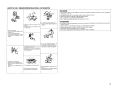
o NOTE ON USE I OBSERVATIONS RELATIVES A L'UTILISATION
CAUTION:
• The ventilation should not be impeded by covering the ventilation openings with items, such as newspapers,
•
•
•
•
• Do not Jet foreign objects into the unit.
• Ne pas laisser des objets etrangers dans
• Keep the unit free from moisture. water,
and dust.
• Proteger rappareil contre I'humidite. I'aau
rappareil.
et la poussiere.
• Avoid high temperatures.
Allow for sufficient heat dispersion when
installed In a rade
• Eviler des temperatures elev6es.
tablecloths, curtains, etc.
No naked flame sources, such as lighted candles, should be placed on the unit.
Observe and follow local regulations regarding battery disposal.
Do not expose the unit to dripping or splashing fluids.
Do not place objects filled with liquids, such as vases, on the unit.
ATTENTION:
• La ventilation ne doit pas Ewe genee en recouvrant les ouvertures de la ventilation avec des objets tels que journaux,
•
•
•
•
rideaux, tissus, etc.
Aucune flamme nue, par exemple une bougie, ne doit etre placee sur I'appareil.
Veillez !l respecter les lois en vigueur lorsque vous jetez les piles usagees.
L'appareil ne doit pas etre expose!l I'eau ou !l I'humidite.
Ne pas poser d'objet contenant du liquide, par exemple un vase, sur I'appareil.
I-------------------j
Tanir compte d'une dispersion de chaleur
suffisante lors de !'installation sur une
etagere.
• Unplug the power cord when not using the
unit for long periods of time.
• Oebrancher Ie cordon d'alimentation
lorsque rappareil n'est pas utilise pendant
• Do not let inseclk:ides. benzene. and
thinner come in contact with the unit.
• Ne pas menre en contact des insecticides.
du benzene at un diluant avec rapparei!.
de Iongues periodes.
• Handle the power cord carefully.
Hold the plug when unplugging the cord.
• Manipuler Je cordon d'alimentation avec
precaution.
Tanir Ia prise lars du debranchement du
cordon.
• (For apparatuses with ventilation holes)
• Never disassemble or modify the unit in
anyway.
• Do not obstruct the ventilation holes.
• Ne pas obstruer les trous d'aeration.
• Ne jamais demonter ou modifier rappareil
d'une maniare ou d'une autre.
n
I
Contents
Cautions on Handling
I
1~~';G};C';}ii~'0'i~
Accessories········································ .. ······· .. ········ .. ······· .. ·· .. ·· ..······· 1
Cautions on Handling· ...... ··· ·
·.. ··.. ·.. ··· ·
·..·.. ·.. ·· · 1
Cautions on Installation .. · ·
2
Preparations·
·.. ·.. ·2
Part Names and Functions ·
·..·
·..·
3
Front Panel·
3
Rear Panel········· .. ·············.. ··· ..·· .. ·.. ·········· .. ·.. ······· ···· .. ···· ..·· .. ···· .. 4
ICp~:,a~.MnP·
. I
Preparations.. ·
5
Cables Used for Connections ·
5
Connecting the speaker cables
·
· ·.. ·
5
Settings
·· .. ·.. ····· .. ······ ··· .. 6
Change the input mode
6
Change the operation mode ·
·
· ·
·
·.. ·.. ·6
Change the control mode .. · ·.. ·
·
·
·6
Connect to AVP-A 1HOCI
·
· ·· · ·
· ·7
Connecting to an RCA input terminal
· ·.. ·..·.. · ·
·7
Connecting to an XLR input terminal .. ·
7
Connecting 2 POA·A1HDCI units to the AVP·A1HDCI· ·.. ·
·8
Settings·· .. ······ ..················ .. ······· .. ······ ······ ..····· .. ········ ..······· ·····8
Settings and Connections· · ·
9
Normal Connections· .. ··· ·.. ·.. ·· .. ····· ·.. · ······· ····· ..··
··· 9
·
·
·
·
· 10
Bi-Amp Connections ···
Bridge Connections
··
·..·
· · ·
· ·
·
·.. ·11
Connecting the External Controller
12
Connecting the Power Cord
12
Once Connections are Completed
12
Turning the Power On
·13
Select the channel to display on the channel level meter········ 13
Set the channel level meter
13
Before any home theater component can be THX Ultra2 certified,
it must incorporate all the features above and also pass a rigorous
series of quality and performance tests. Only then can a product
feature the THX Ultra2 logo, which is your guarantee that the Home
Theater products you purchase will give you superb performance for
many years to come. THX Ultra2 requirements cover every aspect
of the product including power amplifier performance, pre-amplifier
performance and operation. as well as hundreds of other parameters
in both the digital and analog domain.
In addition to improvements to the power amplifier with respect
to previous THX Ultra standards. three surround modes have been
added. the THX Ultra2 Cinema mode. THX Music Mode and THX
Games Mode.
* "THX" and "Ultra2" are trademarks of THX Ltd. THX may be
registered in some jurisdictions. All rights reserved.
* In the NORMAL connection and Bi-AMP connection operation
mode, POA-A1HDCI has acquired THX certification. To play back
data in a manner that complies with the THX standard. use the
NORMAL connection or Bi-AMP connection mode.
• Power is supplied to some of the circuitry even when the unit is
set to the standby mode. When traveling or leaving home for long
periods of time. be sure to unplug the power cord from the power
outlet.
• About condensation
If there is a major difference in temperature between the inside of
the unit and the surroundings. condensation (dew) may form on
the operating parts inside the unit. causing the unit not to operate
properly.
If this happens. let the unit sit for an hour or two with the power
turned off and wait until there is little difference in temperature
before using the unit.
• Cautions on using mobile phones
Using a mobile phone near this unit may result in noise. If so. move
the mobile phone away from this unit when it is in use.
• Moving the unit
Turn off the power and unplug the power cord from the power
outlet.
Next. disconnect the connection cables to other system units before
moving the unit.
Getting Started
• Note that the illustrations in these instructions may differ from the
actual unit for explanation purposes.
Thank you for purchasing this DENON product. To ensure proper
operation. please read this owner's manual carefully before using the
product.
After reading them. be sure to keep them for future reference.
Accessories
Check that the following parts are supplied with the product.
CD Owner's manual
@ Warranty (for North America model only)
® Service station list................
® Power cord (Cord length: Approx. 5 ft /1.5 m)
® Control link cable (Cord length: Approx. 10 ft /3 m)
1
• Before turning the power switch on
Check once again that all connections are correct and that there are
no problems with the connection cables.
..
..
1
1
1
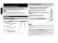
Cautions on Installation
Preparations
Note:
For proper heat dispersal, do not install this unit in a confined
space, such as a bookcase or similar enclosure.
,:;;
*
~
!* Note
IgCJgl
. . .
".
I
Before using this unit. the following steps should be followed. according to the situation in which the unit will be used.
.
"Connection and Settings"
(l3Fpage 5)
*
I---
~
Wall
"OPTION/1/2 mode selection"
(l3Fpage 6)
Set the operation mode and input mode,
then connect the speakers
• Normal Connections
(l3Fpage 9)
• Bi·Amp Connections
(l3Fpage 10)
• Bridge Connections
(l3Fpage 11)
-N,n• Since this unit is very heavy, when installing it on a rack etc, the
maximum load capacity of the rack should always be checked first.
Please refer to the user manual for the rack for the maximum load
capacity.
• Always have at least two people work together to move the POAA1HDCI.
Set the control method
All setup options are carried out
using the AVP-A 1HDCI setup
menu. ("Connect to AVP-A1HDCI"
(l3Fpage 7))
"Connecting the External Controller"
(l3Fpage 12)
Operations ("Operations" (l3Fpage 13))
2
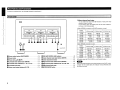
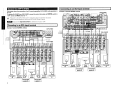
Part Names and Functions
o About channel level meter
You can select the output level (dB indicator) of each power amp
channel to check the meter.
If a sine wave is input. the output power for the meter indicator is
as shown in the following table.
• When NORMAL connection or Bi-AMP connection is used
-~;
Output
indicator
•
:.
Power operation button (ON/STANDBY)··
(13)
f) Power indicator··
•
Power switch (_ON .OFF)·····
o Left channel meter select button (METER)
o Left channel meter indicators (L1 / L2 / L3 / L4)··
o Left channel level meter
•
3
. (13)
.
•
0
:.
~~
300 (mW)
30 (mW)
200 (mW)
150 (mW)
-40 (dB)
-50 (dB)
3 (mW)
20 (mW)
2 (mW)
15 (mW)
1.5 (mW)
I -~-
Output
indicator
6 O/ohms load
8 O/ohms load
800(W) *
80(W)
600 (W)*
-20 (dB)
1200 (VII) *
120(W)
12(W)
-30 (dB)
1200 (mW)
8 IV'J)
800 (mW)
-40 (dB)
120 (mW)
80 (mW)
600 (mW)
60 (mW)
-50 (dB)
12 (mW)
8 (mW)
6 (mW)
o (dB)
PRE AMP CONTROL UNK indicator·· .... ...
.
(6)
(13)
i> Center channel level meter
. . Right channel meter select buttons (METER)
(13)
(13)
• Right channel meter indicators (R1 / R2 / R3 / R4)
. . Right channel level meter..........
(13)
METER ON/OFF button
15 IV'J)
1.5(W)
4 O/ohms load
-10 (dB)
o Center channel meter select button (METER)
•
150(W)
• When BRIDGE connection is used
(13)
Center channel meter indicators (L5 / AS)············· .. ·· .. ··.····· (13)
200 (VII)
20(W)
2(W)
-30 (dB)
(13)
... (13)
300 IV'J)
30 IV'J)
3 IV'J)
-20 (dB)
=!=
liI
•
8 O/ohms load
(dB)
-10 (dB)
L: ~ ;....~.~J
·:11:";
Co.
6 O/ohms load
o
-If
---L.I~J
========
1..~ ~ :Ll··~··i
4 O/ohms load
. (13)
.
(13)
(13)
*
60 IV'J)
6(W)
Possible output by POA-A1HDCI is up to the rated output.
-NI"-
When outputting a program source that has data such as SACD. which
is higher than the audible band. the indicator moves differently than
the volume you hear.
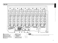
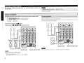
I Rear Panel
~--"1
f,....-------,
I
liD
(SIll
liD
COlD-BROOE- HOT
1'_
16)
8
Operation mode select switch
(6)
•
Mode select switch (MODEl··
(6)
e CONTROL LINK connectors·
o Control select switch (CONTROLI
o TRIGGER IN jack··
·17. 8)
(6)
(12)
CD
1r
IseR)
1
COlD-BRDGE-HOT
1'_
f) RS·232C connector
ID
liD
Ie)
ISBlJ
COlD-BRtOGE- HOT
1r
I
~
COLD-BRiDGE-HOT
1'_
I'onJyJ
;l.L. ••••••••••••••••• • ••••••••••••••••• • ••••••••••••••••• • •••••••••••••••••
=..=...=..=..=..:il.h;••:=:••=
...=..=
...=..=
..
!--:;-;,==;-;dJ.,!;,.=
••:=:
••':"'
•••"••:-::
'; ••=
..=•• I.Ll:=
•••=..
o Input select switches··
llf
..
·····112)
.
(12)
e AC inlet (AC IN)
.
o Speaker terminals
(SPEAKERSI····(5. 7. 9 - 11)
e XLR input connectors
17.
1I
I
I
ID
••••••••••••••••
-n·n-
The 0 - • and 0 must be set before turning the power on. Settings which are changed after powering
on will not be registered. In such cases. the power should be switched off and on again.
9 - 11)
.. RCA input connectors··
(7. 9 - 11)
4
Carefully check the left (L) and right (R) channels and + (red) and - (black) polarities on the speakers being
connected to the POA-A 1HDCI, and be sure to interconnect the channels and polarities correctly.
Connections and Settings
Connections for all compatible audio signal formats are described in these operating instructions.
Please select the types of connections suited for the equipment you are connecting.
With some types of connections. certain settings must be made on the POA·A1HDCI. For details.
refer to the instructions for the respective connection items below.
.N.Ua
•
•
•
•
'1.. cable,
Peel offabout 0.03 ft /10 mm ofsheathing from
tip of the speaker
then either
the core wire tightly or terminate
the
twist
2 Turn the speaker tenninal oounterclockwiseto loosen
~
it.
it.
Do not.plug in the power cord until all connections have been completed.
When making connections. also refer to the operating instructions of the other components.
Be sure to connect the left and right channels properly (left with left, right with right).
Do not bundle power cords together with connection cables. Doing so can result in humming or noise.
4
Preparations
TUJ;R the s~~r ~.~.c1QCkwise to tighten it.
Tighten the speaker terminal firmly before inserting the banana plug.
Select the cables according to the equipment being connected.
Analog connections (XLR)
~ Output
Balanced cable
Analog connections (RCA)
{Input
Pin-plug cable
(Input
r
Output
'N,ua
• Connect the speaker cables in such a way that they do not stick out of the speaker terminals. The
protection circuit may be activated if the core wires touch the rear panel or if the + and - sides touch each
other (Gf" Protection circuit).
• Never touch the speaker terminals while the power supply is connected. Doing so could result in electric
shock.
Speaker connections
+
)liiiiiiiiiiiiii~(
Speaker cables
5
+
If speakers with an impedance lower than specified are used for an extended period of time with the
volume turned up high, the temperature may rise, activating the protection circuit.
When the protection circuit is activated, the speaker output is shut off and the power indicator flashes
red. If this happens, unplug the power cord. then check the speaker cable and input cable connections.
If the set is extremely hot, wait for it to cool off and improve ventilation around it. Once this is done. plug
the power cord back in and turn the set's power back on.
If the protection circuit is activated again even though there are no problems in the ventilation around the
set nor in the connections, the set may be damaged. Turn the power off, then contact a DENON service
center.
Settings
-M·n8
The MODE, CONTROL, Operation mode select switch and Input select
switch must be set before turning the power on. Settings which are
changed after powering on will not be registered. In such cases, the
power should be switched off and on again.
: Operates the unit from the AVP-A 1HOCI (~page
Use XLR. terminal.,
n.
Use RCA terminal.
[Rear panell
Operation mode
select switch MODE
~:~:~:)'i%t.
• t~i;
__,':":"
.
•....•~.~.V).'ll~I:·· :. Control m...ode is not used.
'.'
_
Channel is not used.
lRTh@<!:,~..""~%jv
·f~:
'.
-M·n8
.:
_
Operates the unit from equipment connected
to the RS-232C connector or TRIGGER IN iaclc
(~page12).
• When the input and Input select switch setting on the unit are
different. the unit does not operate.
• If CONTROL is set to "AVP", this setting is invalid.
When CONTROL is set td' AVP", the PRE AMP CONTROL LINK indicator lights in blue.
OPTION I 1 I 2 mode selection
Use control link to connect POA-A1HOCI and AVP-A 1HOCI and switch
POA-A1HOCI according to the number of units to be connected.
Bi-AMP I NORMAL I BRIDGE mode selection
Select MODE.
Set how to use the power amp with each channel.
.liiiili.: for future use, if the range of functions is expanded.
Set the Operation mode select switc;b.
..."."._.,.~
.li!fi~: Used as tile first unit when one POA-A1HOCI unit is
.
), . used or two POA-A1HOCI units are connected.
_
·L_---"';./r.."'·-·-~1i
Input select
switch
.'
.•!U!t...~: Used. for Bi-Amp connection.
.'
..
-
..
--
--
l"
.
: Ulied forNORMAL connection.,
: Used as the second unit when two POA-A1HOCI units
are connected.
-N·n8
• Channels that have the input mode set to "OFF" can not be
selected.
·If CONTROL is set to "AVP", this setting is invalid.
6
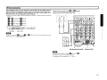
IConnecting to an XLR inpu~ terminal·
Connect to AVP-A1HDCI
~.
This example shows the connection of an AV sound preamplifier AVP·A1HDCI (sold separately) to
the unit,
To operate POA-A1HDCI from AVP-A1HDCI. connect the control link cable. set CONTROL switch to
"AVP" and then set MOOE switch to "1",
Example: 7-channels (NORMAL setting)
• Please refer to the AVP-A 1HDCI owner's manual for setup and operation instructions.
• When connecting, please also refer to the AVP-Al HDCI owner's manual.
-u.n.
I Connecting to an RCA input terminal
Always set the Input select switch for channels not in use to "OFF".
Example: 7-channels (NORMAL setting)
AVP-A1HDCI
Control
link cable
(included)
Control
link cable
(included)
7
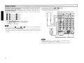
Connecting 2 POA-A1HDCI units to
the AVp·A1HDCI
AVP-A1HDCI
The AVP-A 1HOCI can be operated when connected to 2 POA-A1HOCI
units.
Settings
1 Connect the equipment using a control link cable.
2 CONTROL
3 MODEMODE
Set
switch of two POA·AIHDCI units to
"AVP" (Gf'page 6).
Control link cable
(included)
Set
switch of POA-A1HDCI, which is
connected to AVP·A1HDCI, to "1", and the other
switch of POA·AIHDCI to "2" (Gf'page 6).
~!
Please refer to the AVP-A 1HOCI owner's manual for setup and
operation instructions.
POA-A1HDCI (2nd unit)
8
Settings and Connections
Set the rear panel "Operation mode select switch" and "Input select switch" according to the
connection method.
.~[.Ij.
The Operation mode select switch and Input select switch must be set before turning the power on.
Settings which are changed after powering on will not be registered. In such cases, the power should be
switched off and on again.
I· Normal Connections·
Connection for signal input to each channel to be output from the channel's speaker terminal.
• Set each switch as shown below.
CD Set the Operation mode select switch to "'NORMAL"' (GT'page 6).
@ Set the Input select switch according to the input (GT'page 6).
. For RCA input
Set to "'RCA"'.
. For XLR input······· Set to "'XLR"'.
Bi-wiring connection
When using speakers that have input terminals for both woofer units and tweeter units, this connection
allows for the same signal to be output from each unit.
With this connection the interference between signals for the woofer unit and tweeter unit is low so that
you can enjoy high quality sound in playback.
0 channel
*Setup each channel 1111- •. 0 -111) using the same steps.
Example: Normal connection to the
--AUDIQ--
--AUDIO--
PRE
PRE
;
~
SPEAKER B
II
HIGH
SPEAKER A
"@"
~D·-~
"@"
e
e
~
Ej)
o
~
Input select switch
Ej)
Operation mode select switch
'~[e$,.
Input select switch
• ¢t,jj.
"The same signal is output to speakers A and B.
• Please use the following speaker impedance.
. When using only speaker A or B ····························4 - 16 O/ohms
. When using speakers A and B at the same time ···8 - 16 O!ohms
9
Operation mode select switch
When using Bi-Wiring connection use 4 - 16 OIohms speakers for the impedance.
When using speakers that have input terminals for both woofer units and tweeter units. this
connection outputs one input signal from the two amps on the main unit to each of these units.
With this connection the interference between signals for the woofer unit and tweeter unit is
eliminated so that you can enjoy high quality sound in playback.
• Bi-Amp output is setup using the following combination of channels. The input terminals to be used are
as follows.
•
and
m
input terminal:
m
iii and. input terminal: •
Example: Bi·Amp connection using. and
m channels
'* Setup each pair channel using the same steps.
--AUDIO--
channels
channels
m and III input terminal: III channels
PRE
PRE
OUT
OUT
.~
G
III and. input terminal: III channels
III and IfJ input terminal: III channels
• Set each switch as shown below.
CD Set the Operation mode select switch to "Bi-AMP" ((J"page 6)
@ Set the Input select switch according to the input ((J"page 6) .
. For RCA input
Set to "RCA'· .
. For XLR input·
Set to "XLR".
•.....~"'[·!"l'i""j"'l·..
The input terminal (channel. in case of •
and
regardless of the status of Input select switch.
m) that is not used for this setting becomes invalid
HIGH
Operation mode select switch
-N·U•
• The same signal is output to channel. and channel
• No signal is output from the speaker B terminal.
• Use speakers with an impedance of 4 - 16 O/ohms.
Input select switch
m.
10
I Bridge Connections
This connection is used to use two power amps to output opposite phase signals generated from
one input signal using two power amp units.
By connecting the output (+ side) of the two power amps to the speaker, a larger output than in a
normal connection is possible.
" Bridge output is setup using the following combination of channels. The input terminals to be used are
as follows.
Example: Bridge connection using
liD and iii channels
'* Setup each pair channel using the same steps.
---AUDIO--
liD and iii input terminal: iii channels
liD and liD input terminal: liD channels
liD and ID Input terminal: ID channels
PRE
PRE
OUT
OUT
@
ID and m Input terminal: ID channels
m
~
1· 4
. . and
input terminal: . . channels
" Set each switch as shown below.
Q) Set the Operation mode select switch to "BRIDGE" (@"page 6).
® Set the Input select switch according to the input (@"page 6).
. For RCA input··· ..... Set to "RCA".
For XLR input·········· Set to "XLR" .
.....~"'[.!!'!i~j'!!l...
liD
liD
iii)
"The input terminal (channel
in case of
and
that is not used for this setting becomes
invalid regardless of the status of Input select switch.
"About output by this connection. the voltage applied to the speaker is 6 dB higher than the output
when the normal connection is used. Adjust the input signal using the volume of the pre-amp when
connecting.
"@"
00
"
"
Operation mode select switch
Input select switch
'~[.jj.
• No signal is output from the "-" terminal of speaker A. or the speaker B terminal.
• Use speakers with an impedance of 4 - 16 OIohms
" Do not connect a speaker using other than the specified combination of channels.
11
Connecting the External Controller
When using the following functions, set the CONTROL switch to -EXTERNAL
Connecting the Power Cord
M.
Wait until all connections have been completed before connecting the power cord.
To wall-mounted
power outlet
lAC 120 V. 60 Hz)
* In order to fully demonstrate the ability of POAA 1 HDCI. connect the unit to a larger current
capacity outlet (at least 15 A is recommended).
Also. be sure that the total power consumption
of all devices connected to the outlet does not
exceed the outlet capacity.
<:
.~(.ii.
-Insert the AC plugs securely. Incomplete connections could cause noise.
- The power plug must be connected to a wall-mounted power outlet.
- Do not connect the unit to an integrated AC outlet on another product or to extension cord.
Once Connections are Completed
ITurning the Power On
lGf"page 13)
12
C)
;..
-
Select the channel to display on
the channel level meter
IFront panel]
""~
=;
~
Operations
Pr~
....
(;;: ; ....
of
Turning the Power On
Press
POWER.' . , .
'. '. >
METER.
The indicator of the sel.ected channel meter turns green and the
outPlit level the selecte<f chaO/iel is indicated on the meter.
'"
.••.•
/..
'.J'
',' ... .••.
-
1.rhe power ind.icator lights, red and the power )s set to the
,~tandby mode." .
.
.
I
~]I-W-ER- -,;=r- ETI=:J-E" "TR- M-ET-J~NJOF
ON/STANDBY
ONISTANDBY~ .
The power indicator flashes in green for several seconds and the
power is turned on.
.
2 Press
-kril,.
.'-:j
Before tuning on the power, lower the sound volume of the connected
equipment.
Turning the Power Off
(j)Press ON/STANOBY.
The power is set to the standby mode.
@Press POWER.
The power indicator turns off, and so does the power.
-@!.jiPower continues to be supplied to some of the circuitry even when the
power is in the standby mode. When leaving home for long periods of
time or when traveling, either press POWER to turn off the power, or
unplug the power cord from the power outlet.
B--J
- Channels for which Input selectswiteh is set to "OFF" are skipped.
-In the case of bi-amp connection, the indicator of the input-side
channel meter of the selected channel pair turns green.
.In the case of a bridge connection, the indicator of the channel meter
of the selected channel pair turns green.
Set the channel level meter
S8t
0r,/OFF vf all
~lli" Inel 18V81 fT1tit81 S
rressMETER ON/OFF..
~".'>.i1;
.. ' 011$:*;
~~="~
•
•
The channel level meter is illuminated and the channel
level meter operates. .
.
.
: The channel level meter illumination and the channel
meter indicator turn off and the channel level meter
does not ~.rate.
The PRE AMP CONTROL LINK indicator goes off if set to "OFF" with
the AVP-A 1HOCI connected to the control link.
13
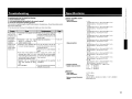
Specifications
Troubleshooti n9
If a problem should arise, first check the following:
1. Are the connections correct?
2. Is the set being operated as described in the owner's manual?
3. Are the other components operating properly?
If this unit does not operate properly, check the items listed in the table below. Should the problem persist,
there may be a malfunction.
In this case, disconnect the power immediately and contact your store of purchase.
Power does not
• Connection of the power cord is • Check that the power plugs are
faulty.
securely inserted into the POAturn on', or turns
off directly after it
A 1HDCl's AC inlets and the wall
was turned on.
power outlet.
No sound is
• Connection with the input • Check the connections.
devices or connection of the
produced from
speakers.
speaker cables is faulty.
Power turns off
• Protection circuit activated due • Turn off the power, wait for the
suddenly and
set to fully cool down, then turn
to rise of internal temperature.
power indicator
the power back on.
flashes red.
• Place the set in a well-ventilated
place.
• Core wires of two speakers are • First unplug the power cord,
touching each other or a core then twist the core wires tightly
wire is sticking out of the terminal or terminate the speaker cables,
and touching the set's rear panel,
then reconnect.
activating the protection circuit.
• Speakers with an impedance • Use speakers with the specified
other than specified are being impedance.
used.
• Turn off the power and contact a
• Set is damaged.
DENON service center.
o Power amplifier section
• Rated output:
Normal connections:
12
5,9- 11
Bridge connections:
5
5
5
9 -11
• Frequency response:
• Speaker output connectors:
o General
Power supply:
Power consumption:
Maximum external dimansions:
Weight:
Ll/ R1:
150 W (8 O/ohms, 20 Hz - 20 kHz with 0.05 % T.H.D.)
300 W (4 O/ohms. 1 kHz with 0.7 % T.H.D.1
L2/ R2:
150 W (8 O/ohms, 20 Hz - 20 kHz with 0.05 % T.H.D.)
300 W (4 O/ohms, 1 kHz with 0.7 % T.H.D.)
L3/ R3:
150 W (8 O/ohms, 20 Hz - 20 kHz with 0.05 % T.H.D.)
300 W (4 O/ohms, 1 kHz with 0.7 % T.H.D.)
L4/ R4:
150 W (8 O/ohms, 20 Hz - 20 kHz with 0.05 % T.H.D.)
300 W (4 O/ohms, 1 kHz with 0.7 % T.H.D.)
L5/ R5:
150 W (8 O/ohms, 20 Hz - 20 kHz with 0.05 % T.H.D.)
300 W (4 O/ohms, 1 kHz with 0.7 % T.H.D.)
L1 + L2:
300 W (8 O/ohms, 20 Hz - 20 kHz with 0.05 % T.H.D.)
500 W (4 O/ohms, 1 kHz with 0.7 % T.H.D.)
L3 + L4:
300 W (8 O/ohms, 20 Hz - 20 kHz with 0.05 % T.H.D.)
500 W (4 O/ohms, 1 kHz with 0.7 % T.H.D.)
L5 + R5:
300 W (8 O/ohms, 20 Hz - 20 kHz with 0.05 % T.H.D.)
500 W (4 O/ohms, 1 kHz with 0.7 % T.H.D.)
R1 + R2:
300 W (8 O/ohms, 20 Hz - 20 kHz with 0.05 % T.H.D.)
500 W (4 O/ohms, 1 kHz with 0.7 % T.H.D.1
R3 + R4:
300 W (8 O/ohms, 20 Hz - 20 kHz with 0.05 % T.H.D.)
500 W (4 O/ohms, 1 kHz with 0.7 % T.H.D.)
10 Hz - 100 kHz (8 O/ohms, +1, -3 dB (at 1 W))
A or B
4 - 16 O/ohms
A +B
8 - 16 O/ohms
Bi-wiring 4 - 16 O/ohms
I
AC 120V, 60 Hz
12A
0.3 W (Standby)
434 (W) x 281 (H) x 530 (D) mm (17-3/32" x 11-1/16" x 20-55/64")
60 kg (132 Ibs 4oz1
14
DENON
www.denon.com
Denon Brand Company, D&M Holdings Inc.
Printed in Japan DOD 511 4608005
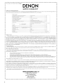
DENON SERVICE NETWORK I ijIH~~~
•
•
•
•
•
•
•
•
Please consult the outlet where the equipment was purchased.
Bitte wenden Sie sich an den Handler, bei dem Sie das Produkt gekauft haben.
SVP veuillez consulter votre revendeur.
Neemt u alstublieft contact op met het verkooppuntwaar u de apparatuur heeft gekocht.
Por favor consulte en el establecimiento donde compro el equipo.
Vanligen ta kontakt med butiken dar du kopt utrustningen.
Rivolgetevi al rivenditore che vi ha venduto I'apparecchio.
Contacte a loja onde comprou 0 equipamento.
• ~1[1;)11F1ll.A~mEr-Jiflj~!n!!:~ 0
• tw[C]11FJiJf~~~mEr-JiIJHT~i1iJ 0
Australia
Audio Products Group Pty Ltd. 67 O'Riordan Street Alexandria NSW 2015. PO Box 150, Mascot NSW 1460 Australia
Tel: 1300 134400 Fax +61 295780159
Austria
Digital-Professional-Audio Vertriebsges.m.b.H., Seeb6ckgasse 59, A-1160 Wien Tel: 01-480-1006 Fax: 01-485-7679
Transtel-Sabima PVBA Duboisstraat 48, B-2060 Antwerpen, Belgium Tel: 03-237-3607
Belgium
D&M CANADA INC. 5-505 Apple Creek Blvd., Markham, Ontario, L3R 5Bl Tel: 905-475-4085 Fax: 905-475-4159
Canada
rttf@:jil'J';''t nl~ t'1 M( I: #it )1'i [~R 0 PlL #itTTi i1t ep ~887 -E}:ik ;j'4r*~ 601 0 'ir
China
"!ii?i(021 )64372299 f~U(021 )64339973 ItIllt11l1: 200020 :t':jt~FmH~·J:MoJi.: 021-62949285
EUROSTAR OSTRAVA sro areal Vodni stavby Praha, budova A2 Dobronicka 635,14800 Praha 4 Czech Rep.
Czech republic
Tel: 261-112-901 Fax: 261-112-904
Hifi Klubben A/S Dali Aile 1, 9610 Noerager, Denmark Tel: 45-96 72 1000 Fax: 45-96 72 10 14
Denmark
Finland
Soundata Oy Hameentle 157 5th floor 00560 Helsinki Finland Tel: +358-(0)9-47693300 Fax +358-(0)9-47693310
DENON FRANCE A division of D&M France SAS Tour Ventose, 2 rue des Bourets, 92156 Suresnes Cedex, France
France
Tel +33(0)1-41-383230 Fax +33(0)1-41-380110
DENON DEUTSCHLAND A division of D&M Germany GmbH An der Landwehr 19, D-41334 Nettetal, Germany
Germany
Tel +49(012157-1208-0 Fax +49(0)2157-1208-15
Greece
KINOTECHNIKI LTD. 14, PYRGOU STR. 16675, GLYFADA ATHENS Tel: +302109601071 Fax +302109601072
Hong Kong
D&M Sales and Marketing (HK.I Ltd. Unit 501, Ocean Centre, Harbour City, 5 Canton Road, TSlmshatsui, Kowloon, Hong Kong
Tel: 852-2516-5864 Fax: 852-2516-5940
*i!n~~~ij;n.l3.r.;r*j]!5~1EJA!:J:fiX)iji$ep,L'5~501'ir fG:~3: 852-2516-5864 f~ffi!;: 852-2516-5940
A.IDA Audio Kft. 1112 Budapest Olt u. 37. Hungary Tel: 01-248-2030 Fax: 01-248-2039
Hungary
Iceland
Einar Farestveit & co hf., Borgartun 28, PBox 5440, 125 Reykjavik Tel: +3545207900 Fax: +3545207910
India
PROFX SERVICE CENTRE Advanced Audio Solutions (Bangalore)Pvt. Ltd.
No 53, KHRoad, Opp .Big Bazaar, Bangalore - 560 027, India Tel 08032970853 Fax 0802211 2043
Indonesia
PT Autoaccindo Jaya Cideng Barat NO.7 Jakarta, Indonesia Tel: +62-21-633-2730 Fax: +62-21-632-2886
Israel
Newpan Ltd. 14 Rosansky st. Rishon Lezion 75706, Israel: Tel: +972-3-953-5900 Fax: +972-3-961-6193
Italy
Audiodelta Srl19 Via Pietro Calvi 20129 Milano Italy Tel: 39-02-5411-6008/39-02-5412-8253 Fax: 39-02-5412-0258
Korea
D&M Sales and Marketing Korea Ltd. Chung Jin B/D., lOF, 53-5, Wonhyoro 3 Ga, Yongsan-Gu, Seoul. 140-719, Korea
Tel: 02-715-9041 Fax 02-715-9040
Malaysia
Wo Kee Hong Trading Sdn Bhd. 2nd Floor, (Left Wing), Bangunan Infinite Centre, Lot 1, Jalan 13/6, 46200 Petaling Jaya,
Selangor Darul Ehsan, Malaysia Tel: 03-7954-8088 Fax: 03-7954-7088
Mexico
Labrador, SA de C.v. Callejon del Naranjo 35, Naucalpan, 53560, Edo. Mex, Mexico Tel: 52-5359-5161 Fax: 52-5357-1775
Netherlands
Penhold BV Poppenbouwing 58, NL-4191 NZ Geldermalsen, Netherland Tel: 31-345-588 080 Fax: 31-345-588 085
New Zealand
Avalon-Pacific Marketing Limited. 15C Vestey Drive, Mt Wellington, Auckland, New Zealand.
PO Box 11 631 Ellerslie, Auckland, New Zealand Tel: +64-9-573-5933 Fax: +64-9-573-3720
Norway
Hi-Fi Klubben Marcus Thranes gate 4-6, 0473 Oslo, Norway Tel: +47228063 10 Fax: +4722806329
Philippines
Lotteworld Audio Video Systems Incorporated CET Building Mezzannine Floor NO.4 Mindanao Avenue, Barangay
Bahay Toro, Project 8, Quezon City, Philippines Tel: +632-929-5334 Fax: +632-929-1343
Poland
HORN DISTRIBUTION SA Ulica Kurantow 34, 02-873 Warszawa Poland Tel: +4822331 5533 Fax: +4822331 5500
Portugal
Videoacustica Qta. Do Paizinho-Armazem 5-Estrada De Circunvalac;:ao-Apart. 31271303 Lisboa Codex
Tel: +351214241770 Fax +351214188093
Singapore
ALL (E&EI Service Center Pte Ltd. Machtech Industrial Building, #06-04, No.2, Kallang Pudding Road, Singapore 349307
Tel: 6747-8274 Fax: 6748-9007
Slovakia
BIS AUDIO STO. Dobronivska cesta 1642/696001 Zvolen Tel:045-5400 703 Fax 045-5400 704
South Africa
Mandarin Distributors SA 10 Thora Crescent, Wynberg Ext.3 Sandton, PO.Box 5137, Johannesburg Republic of South
Africa Tel: 27-11-444-8445 Fax: 27-11-444-8363
Spain
Gaplasa SAAV Ing. Conde de Torroja, 25, 28022 Madrid Tel: 91-746-00-45 Fax: 91-329-44-57
Sweden
Hi-Fi Klubben G6teborg Skanegatan 25, 41252 G6teborg Tel:031 3351010 Fax 031 3351019
Switzerland
DKB household AG, Abteilung Elektronik. Eggbuhlstrasse 28, CH-8052 Zurich, Switzerland
Tel 01-306-1626 Fax 01-306-1690
Taiwan R.O.C.
D&M Sales and Marketing Taiwan Ltd. 6F-2 N0148, Songjiang Rd, Taipei City 10458, Taiwan R.O.C.
Tel: 02-2522-1308 Fax: 02-2100-1175
Thailand
Mahajak Development Co, Ltd. 46 Mahajak Building, Sukhumvit Soi 3 (Nana-Nua) Klongtoey, Wattana, Bangkok
Thailand. 10110 Tel: 66-2-256-0020 Fax 66-2-253-1696
Turkey
Ertekin electronik t c. ve san. a.s. Galipdede Caddesi No.: 113 Kuledibi-Karak6y / Istanbul, Turkey
Tel: +90(212)293-9515 Fax: +90(212)249-3512
U.A.E.
VV & SONS L.L.C. Street No-ll/B, Road NO-128, Shed No-39 AI Khabisi, Deira, Dubai, UAE
Tel: +971-4-266-2435, 268-4575 Fax +971-4-266-2052
Ukraine
Mirs Ltd. Osipova str 37/0ffice 1,65012 Odessa, Ukraine
Tel: +380(482)305530 Fax: +380(482)305555
United
DENON UK A division of D&M Audiovisual Ltd. Moorbridge House, Padbury Oaks, 579 Bath Road,
Kingdom & Eire
Longford, Middlesex, UB7 OEH, United Kingdom Tel: +44(0)1753-680568 Fax: +44(0)1753-689697
U.S.A.
DENON ELECTRONICS (USA), LLC (a D&M Holdings Company)
100 Corporate Drive, Mahwah, NJ 07430-2041 Tel: 800-497-8921 Fax: 888-544-8434
Vietnam
Anh Duy Manufacturing -- Trading Co., Ltd. 170 Ung Van Kheim St., Ward 25, Blinh Thanh Dist., HCMC, Vietnam
Tel: +8488983424 Fax +8488983425
m
•
•
•
•
•
•
•
•
•
If there is no service center in your local area, please contact one of our overseas service centers, listed above, for follOW-Up service consultation.
1st kein Service-Center in Ihrer Nahe, setzen Sie sich bitte miteinem der hier aufgelisteten Adressen in Verbindung.
Si il n'y a pas destation technique proche de chez vous, veuillez contacter nos I' un de noscentres techniques, listes ci dessous, pour toutes demandes techniques.
Ais er geen servicecenter bij uin de buurt is, neem dan contact op een een van onze bovengenoemdeservicecenters voor ondersteuning.
Si no hay un servicio tecnico en su zona, por favor contacte can uno de los servicios tecnicos centrales, indicados abajo, para realizar un seguimiento de su consult.
Om det inte finns nagon auktoriserad Denon-verkstad dar du bor, kontakta en av vara internationella servicecentra (se ovan).
Se non ci sono dei cenui assistenza autorizzati nella vostra zona, potete fare riferimento agli altri cent" assistenza autorizzati, vedl elenco sopra, per qualsiasi
consultazione tecnica.
Caso nao exista um centro de assistEmcia lecnica na sua area, consulte um dos centros acima apresentados
~1n5ii"tt!!jfzI!l\Mf,!;rJ)rp,L.' , ~~i!l,jlJ:ftPli)iIJ *£. i"iJfflj 9HIf,!;r!§'P,L.·QBU) fit iJiiIlfifMih 0
l'i"'lIll!XIJlH~·rl',L.'. mJf;k;f.l-.ifr'lr'ilJt!df·JI'i'Ji'f~~}'II~%r:p,C.·. L(rJ!i~piJ',jdIlHh'ij1~
0
DENON
www.denon.com
Denon Brand Company, D&M Holdings Inc.
Printed in Japan OOD 5150921 908 iii 709
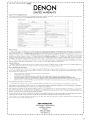
DENON®
LIMITED WARRANTY
(USA / CANADA)
USA (ENGLISH)
CANADA (ENGLISH)
CANADA (FRENCH)
PAGE
2
3
4
USA
DENON ELECTRONICS (USA), LLC
(a D&M Holdings Company)
100 Corporate Drive
Mahwah, NJ 07430-2041
(800) 497-8921
(888) 544-8434 Fax
DENON REGIONAL SUPER SERVICE CENTERS (Repair only-No parts orders please)
PYRAMID AUDIO
UNITED RADIO SERVICE
AUDIO SERVICES
305 E. Braker Lane
Austin, TX 78753-2746
(512) 458-8292
(512) 453-4542 Fax
5717 Enterprise Parkway
E. Syracuse, NY 13057-2905
(800) 634-8606
(315) 446-8505 Fax
544 Central Dr., Suite 101
Virginia Beach, VA 23454-5245
(757) 498-8277
(757) 498-9554 Fax
--------------------------------------------------------------~-----------------------------------
INNER SOUND
NORMAN'S ELECTRONICS
GOLD CROWN ELECTRONICS
1416 S.E. Morrison Street
Portland, OR 97214-2646
(503) 238-1955
(503) 238-1787 Fax
3653 Clairmont Road
Atlanta, GA 30341-4907
(770) 451-5057
(770) 455-8337 Fax
Victoria Business Park
129 E. Savarona Way
Ca rso n, CA 90746-1406
(310) 538-8282
(310) 538-8281 Fax
--------------------------------------------------------------------------------------------------
SERVICE WIDE TECHNOLOGIES
ELECTRONICE EXPRESS
2239 Curtiss Street
Downers Grove, IL 60515-4010
(630) 969-7333
(630) 969-7330 Fax
1809 E. Fabyan Parkway
West Chicago, IL 60185
(630) 208-4600
(630) 208-4601 Fax
CANADA
D&M CANADA INC.
5-505 Apple Creek Boulevard
Markham Ontario, L3R 5B1
(905) 475-4085
(905) 475-4159 Fax
WARRANTY (HOME)
OOD 515 0944 600
1
~"lill'-~'''III''~'''lIh''''''''"I1''''''''III'''''''''IlI'''''''''IlI''''''.,,111' ..... ,,111'.....
;
Th'",""""'Y
w'" b, h",,,,,"" """
i" "" liSA
•
•
DEN 0 N
I
LIMITED WARRANTY
t
"11" ...... '11" .....,11'......."110.......,"" ..... -.,1110·. . . ·,.11"·. . . ·.,11"·. . .·.'11"·. . .·,,1111·. . .·.,11"·. . . ·,,111'·....-.,111.·. . .·.'111'·. . .·.'111'....·.'"1'·. . . ·,,'11··. . .·."11'·. . .·.'111.......,111'.....,"11'.....,,111...... ,,11'.
®
Length of Non-Transferable Warranty
This warranty on your DENON product which is distributed and warranted by DENON ELECTRONICS (USA). LLC remains in effect for the following periods from
the date of the original consumer purchase from an AUTHORIZED DENON ELECTRONICS (USA). LLC DEALER.
,•
•
Product Category
.
~
"
.
•
••
•
•
••t
;
•
t
•t
.
~
•
•
•
·
•
•
~='_'.
•
•
•
t
,Pod
IS
a trademark 01 Apple Computer, Inc. registered
the US. and other countries
What is Covered
Except as specified below. this Warranty covers all defects in material and workmanship in this product occurring during the above warranty periods. The following are
not covered by the Warranty: (I) Any product which is not distributed in the U.S.A. by DENON ELECTRONICS (USA). LLC. (2) Any product which is not purchased in
the U.S.A. from an authorized DEN ON dealer. unless the product is purchased through the U.S.A. Military Exchange Service where the Warranty will be One (I) year for
all products listed above except in the case of Cartridges. Accessories. Remote Controller and Headphone which will remain at 90 days. (Note: AUTHORIZED DENON
DEALERS can be identified by DENON AUTHORIZED DEALER sticker displayed in the stores. If you are uncertain as to whether a dealer is a DENON
AUTHORIZED DEALER. please contact DENON as listed below). (3) Any product on which the serial number has been defaced. modified or removed. (4) Damaged
deterioration or malfunction resulting from: a) Accident. act of nature. abuse, misuse. neglect. unauthorized product repair, opening of or modification or failure to follow
instructions supplied with the product. b) Repair or attempted repair by anyone not authorized by DENON. c) Any shipment of the product (claim most be presemed to
carrier). (5) Items subject to wear from normal usage (tape heads. cartridges. stylus. battery. etc.). (6) Periodic check-ups which do not disclose any defec\. (7) Usc of the
product outside the U.S.A. (8) Damaged magnetic tape or CD/DVD discs. (9) Use in industrial. commercial, and/or professional applications. (10) Any installation or
removal charges resulting from product failure.
What We Will Pay For
If during the applicable warranty period from the date of original consumer purchase your DEN ON product is found to be defective by DENON. DENON will
repair. or at its option. replace with new. used or equivalent model. such defective product withoot charge for parts or labor.
•
~
•
•
t
•
How to Obtain Warranlv Performance
If your unit cver need~ service. it may be taken or shipped to any authorized DEN ON service station or DENON ELECTRONICS (if you are uncertain as to
whether a service station is DENON authorized. please contact DENON as listed below.) In all other cases. the following procedures apply whenever yoor unit must
be transported for warranty service:
a.
b.
•
c.
d.
•
~
t
You are responsible for transporting your unit or arranging for its transportation.
If shipment of your unit is required:
You must pay the initial shipping charges. but we will pay the return shipping charges if the repairs are covered by the Warranty.
WHEN RETURNING YOUR UNIT FOR WARRANTY SERVICE. A COPY OF THE ORIGINAL SALES SLIP MUST BE ATTACHED.
You should include the following: your name. address. daytime telephone number. model and serial number of the product and a description of the
problem. In the case of a CD or DVD Player. please enclose ONE ( I) disc that the unit has failed with for test reasons. It will be returned with the unit.
THIS WARRANTY IS VALID IN THE U.S.A. ONLY
•
•
,
"
4
~
"
•
•
,
"
•
4
4
i.
"
•
~
"
~-
t
•
If your product does not require service. but you have questions regarding its operation. please contact our Technical Serv~ces Department as listed below.
•
4
THIS WARRANTY IS EXPRESSLY MADE IN LIEU OF ALL OTHER WARRANTIES. EXPRESSED OR IMPLIED. INCLUDING WITHOUT LIMITATION.
WARRANTIES OF MERCHANTABILITY AND FITNESS FOR A PARTICULAR PURPOSE.
~_-
OUR LIABILITY IS LIMITED TO THE REPAIR OR REPLACEMENT. AT OUR OPTION. OF ANY DEFECTIVE PRODUCT AND SHALL IN NO EVENT
INCLUDE INCIDENTAL OR CONSEQUENTIAL COMMERCIAL OR PROPERTY DAMAGES OF ANY KIND. WE ARE NOT RESPONSIBLE FOR
PRODUCTS LOST. STOLEN AND/OR DAMAGED DURING SHIPPING.
,
"
•
•
SOME STATES DO NOT ALLOW LIMITATIONS ON HOW LONG AN IMPLIED WARRANTY LASTS AND/OR DO NOT ALLOW THE EXCLUSION OF
INCIDENTAL OR CONSEQUENTIAL DAMAGES. SO THE ABOVE LIMITATIONS AND EXCLUSIONS MAY NOT APPLY TO YOU.
,
•
This warranty gives you specific legal rights. but you may also have other rights which vary from state to state. This Warramy may not be altered other than in a
writing signed by an officer of Denon Electronics USA. LLC.
t
~
"
•
t•
~
•
t
t
•
DENON ELECTRONICS (USA), LLC
(a D&M Holdings Company)
100 Corporate Drive
Mahwah, NJ 07430-2041
(800) 497-8921
d
www.usa.enon.com
.1111.·~'.III'.·~·.llll.·~·.IIII.,~·.IIII.·~·.IIII
•. ~ .• Illl.·~·.lllh.~ •• 'I1I.·~·.IIII.·~·.'III.·~,.IIII.·~·.1111.-~·.'III.·~·.llll·,~·.III'··~·.IIII··~·.'III··~·.llll·,~·.1111··~·.1111··~·.1l11··~·.1111
2
In
•
•
•
4
t
4
4
•
~
•. ~ .• ,!l1·-~·.11111 ......11111......1111.......'11'.......'.11.......1111.......'111.....'11111',"':
~"tllh'~"llIh .....otlll""'-'IIII"""'IIlI, ......tlll"""IIII'.....,1111'.....'11110.....1111'. . . . 11111>..... ,1111..... "111.....'1111.....·•• Ut'·. . .·lI11h·. .·,llIl··. .·.tlll'· . . .·.tlll··. . . ·.tlll··. . .·,'lIl'. . .·.lIl1··. .·.tlll .....
•
·
t
t
t
t
•
~
t
t
t
This warranty will be honored only in
W!llililll.
·.'"I',. . ·.tlll'·. .·.tlll'·. .·,llll.·. .·.tlll.....,,"I'... ,,'IIIo......'UIo.......IIII.
~
DENON®
t~
t
LIMITED WARRANTY
Length of Non-Transferable Warranty
This wamlllty on your DENON product which is distributed and warranted by D&M CANADA INC. remains in effect for the following periods from Ihe date of Ihe
original consumer purchase from an AUTHORIZED D&M CANADA INC. DEALER.
Product Category
t
t
•
t
t4
t
;
t
•
4
t
;
t
t
What is Covered
Exccpt as specified below. this Warranty covers all defects in material and workmanship in this product occurring during the above warranty periods. The following are
not covered by the Warramy: (I) Any product which is not distributed in Canada by D&M CANADA INC. (2) Any product which is not purchased in Canada from an
authorized DENON dealer. (Note: AUTHORIZED DENON DEALERS can he identified by DENON AUTHORIZED DEALER sticker displayed in the stores. If you are
uncenain as to whether a dealer is a DEN ON AUTHORIZED DEALER. please contact D&M CANADA INC. as listed below). (3) Any product on which the serial
number has been defaced. modified or removed. (4) Damaged deterioration or malfunction resulting from: a) AccidCnl. act of nature. abuse. misuse. neglect.
unauthorized product repair. opening of or modification or failure to follow instructions supplied with the product. b) Repair or attempted repair hy anyone not authorized
by DENON. c) Any shipment of the product (claim must be presented to carrier). (5) Items subject to wear from normal usage (tape heads. cartridges. stylus. battery.
etc L (6) Periodic check-ups which do not disclose any defect. (7) Use of the product outside Canada. (8) Damaged magnetic tape or CD/DVD discs. (9) Use in
industrial. commercial. and/or professional applications. (10) Any installation or removal charges resulting from product failure.
•
What We Will Pay For
~
,
~
~_~_.
~ rep~:,~~:I~~i:~eO;;;~~~::~~a~:\:~\~lt)~:-~ri~~~~·r~;l~~~~v~~~~t~~,~~~r:~lc~O~;t~~~~::~;~~~~~
;:,~t~~~~~~ge;.~~~~~:/~rf~~b~r.tobe defective by DENO
tt.
•
•
~
t
•
. DE ON will
How to Obtain Warranty Performance
If your unit ever needs service. it may be taken or shipped to any authorized DENON service station or D&M CA ADA I C. (if you are uncertain as to whether a
service station is DENO authorized. please contact D&M CA ADA INC. as listed below.) In all other cases. the following procedures apply whenever your unit
must be transported for warranty service:
a.
b.
•
•
t
f
t
•
~
•
t
~=._'
t
c
d.
YOLI arc responsible for transporting your unit or arranging for its transportation.
If shipment of your unit is required:
You must pay the initial shipping charges. but we will pay the relUrn shipping charges if the repairs are covered by the Warranty.
WHEN RETURNING YOUR UNIT FOR WARRANTY SERVICE, A COPY OF THE ORIGINAL SALES SLIP MUST BE ATTACHED.
You should include the following: your name. address. daytime telephone number. model and serial number of the product and a description of the
problem. In the case of a CD or DVD Player. please enclose 0 E (I) disc that the unit has failed with for test reasons. It will be relUmed with the unit.
THIS WARRANTY IS VALID IN CANADA 0
LV
t
t
t4
,
=
~_-_o
~_._'
~
,
._~.
t
•
~_:_'.
,
•
:.
•
4
t
,
If your product does not require service. but you have questions regarding its operation. please contact our Technical Services Department as listed below.
D&M CANADA INC.
t~_'
t
t
t
4t
5-505 Apple Creek Boulevard
Markham, Ontario
•
•
L3R 5B 1
,
•
•
(905) 475-4085
www.denon.ca
t
t~
THIS WARRANTY IS EXPRESSLY MADE IN LIEU OF ALL OTHER WARRANTIES. EXPRESSED OR IMPLIED. INCLUDING WITHOUT LIMITATION.
WARRANTIES OF MERCHANTABILITY AND FIT ESS FOR A PARTICULAR PURPOSE.
•
OUR LIABILITY IS LIMITED TO THE REPAIR OR REPLACEMENT. AT OUR OPTION. OF A Y DEFECTIVE PRODUCT AND SHALL IN 0 EVENT
INCLUDE INCIDENTAL OR CONSEQUENTIAL COMMERCIAL OR PROPERTY DAMAGES OF ANY KIND. WE ARE NOT RESPONSIBLE FOR
PRODUCTS LOST. STOLEN AND/OR DAMAGED DURING SHIPPING.
•
1
SOME PROVINCES DO NOT ALLOW LIMITATIONS ON HOW LONG AN IMPLIED WARRANTY LASTS AND/OR DO NOT ALLOW THE EXCLUSION OF
INCIDENTAL OR CONSEQUENTIAL DAMAGES. SO THE ABOVE LIMITATIONS AND EXCLUSIONS MAY NOT APPLY TO YOU.
t
This warranty gives you specific legal rights. hut yOlI may also have other rights which vary from province to province. This Warranty may not be altered other
than in a writing signed by an officer of D&M Canada Inc.
,
tt
,
~
t
'0_._.
..
~
·,1111·· . . .·.111"·. . .·'111'··. . .·,'1110·.....·,'111·· ....·'111"· ....·.111"·....·,lnl',. . .·'IUI'· .....·'IIII'·. . .·,'III·· .....·.III"· ....·.IUIo·. .·.llI"·~·.'u..·. .·.,ul··. . .·.lllu·. .·.,"'··. .·.III'··. . .·.IIlU·. . .·.IUi··. . .·.1lIh·. . .··'II'··. . .·.IIlI··. . .·.llIl··. . .·.llI'··. . .··'nl··. . .·.llII· . . .··'1I,., .....,!lI··. . .··IH'··. . . ··llJI··~
3
Table tournante
I
I
,
2
I
I
Levee auto
Au,a cample'
Syntoniseur, amplificateur integre
Preamplificateur, preampllflcateur numerique
Amplificateur de puissance, Preampliflcateur phono
,
Decodeur surround numerique
I Excluant Ie mecanisme du dlsque dur
Serveur / Client de
I
reseau multimedia
2 I Le mecanisme du disque dur
I
Contraleur A / V, Recepteur A / V, Recepteur AM / FM
Recepteur DVD, Systeme DVD Home Theater
Lecteur CD, Lecteur DVD
Magnetocassette, Enreglstreur CD, Enreglstreur MD
DP-L
DP-F
TU, PMA
4
2
PRA, AVP, DAP, POA, HA
3
AVD
NS
3
3
3
-
,
AVC, AVR, DRA
ADV, S
DCD, DCM, DP, DA, DVD, DVM
DRM, DRR, DRS, DRW, CDR, CDRW, DMD, DTR
,
,
,
Systeme Audio
D IUPA, UTU, UDCM, UDR, USC, USR, UCD, UDRAI
D-M, D-A, D-C, CDR-M,DRR-M, S
Haut-parleurs
Sub-woofer
Systemes Karaoke
Micro
Dock de contrale pour IPod®
Casque d'ecoute
Cellule phonolectrlce, Accessoires
Telecommande
SC
DSW
DCC, HMA
DM-S
ASD
AH-D, AH-C
DL, AU, DM-K, DME
RC
2
ANNEES
,
,
,
2
,,
2
90
90
JOURS
Apple et IPod sonl des marques commerClales d Apple Computer, Inc, deposees aux Etals-Unls et dans d'aulres pays
CETTE GAR ANTlE EST VALABLE SEULMENT AU CANADA,
4