1
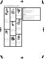
POWER AMPLIFIER
POA-A1HDCI
Owner’s Manual
1.POA-A1HDCIEU.indd
1
2008/01/18
11:06:49
nSAFETY PRECAUTIONS
CAUTION
RISK OF ELECTRIC SHOCK
DO NOT OPEN
CAUTION:
TO REDUCE THE RISK OF ELECTRIC SHOCK, DO NOT REMOVE
COVER (OR BACK). NO USER-SERVICEABLE PARTS INSIDE.
REFER SERVICING TO QUALIFIED SERVICE PERSONNEL.
The lightning flash with arrowhead symbol, within an equilateral
triangle, is intended to alert the user to the presence of
uninsulated “dangerous voltage” within the product’s enclosure
that may be of sufficient magnitude to constitute a risk of electric
shock to persons.
The exclamation point within an equilateral triangle is intended
to alert the user to the presence of important operating
and maintenance (servicing) instructions in the literature
accompanying the appliance.
WARNING:
TO REDUCE THE RISK OF FIRE OR ELECTRIC SHOCK, DO NOT
EXPOSE THIS APPLIANCE TO RAIN OR MOISTURE.
CAUTION:
To completely disconnect this product from the mains, disconnect the plug
from the wall socket outlet.
The mains plug is used to completely interrupt the power supply to the unit
and must be within easy access by the user.
PRECAUTION:
1.
2.
3.
4.
5.
6.
7.
8.
9.
10.
11.
12.
13.
IMPOTANT SAFETY
INSTRUCTIONS
Read these instructions.
Keep these instructions.
Heed all warnings.
Follow all instructions.
Do not use this apparatus near water.
Clean only with dry cloth.
Do not block any ventilation openings.
Install in accordance with the manufacturer's instructions.
Do not install near any heat sources such as radiators, heat registers, stoves,
or other apparatus (including amplifiers) that produce heat.
Do not defeat the safety purpose of the polarized or grounding-type plug. A
polarized plug has two blades with one wider than the other. A grounding
type plug has two blades and a third grounding prong. The wide blade or the
third prong are provided for your safety. If the provided plug does not fit into
your outlet, consult an electrician for replacement of the obsolete outlet.
Protect the power cord from being walked on or pinched particularly at
plugs, convenience receptacles, and the point where they exit from the
apparatus.
Only use attachments/accessories specified by the manufacturer.
Use only with the cart, stand, tripod, bracket, or table
specified by the manufacturer, or sold with the apparatus.
When a cart is used, use caution when moving the cart/
apparatus combination to avoid injury from tip-over.
Unplug this apparatus during lightning storms or when
unused for long periods of time.
14. Refer all servicing to qualified service personnel.
Servicing is required when the apparatus has been damaged in any way,
such as power-supply cord or plug is damaged, liquid has been spilled or
objects have fallen into the apparatus, the apparatus has been exposed to
rain or moisture, does not operate normally, or has been dropped.
FCC INFORMATION (For US customers)
1. PRODUCT
This product complies with Part 15 of the FCC Rules. Operation is subject
to the following two conditions: (1) this product may not cause harmful
interference, and (2) this product must accept any interference received,
including interference that may cause undesired operation.
2. IMPORTANT NOTICE: DO NOT MODIFY THIS PRODUCT
This product, when installed as indicated in the instructions contained
in this manual, meets FCC requirements. Modification not expressly
approved by DENON may void your authority, granted by the FCC, to use
the product.
3. NOTE
This product has been tested and found to comply with the limits for
a Class B digital device, pursuant to Part 15 of the FCC Rules. These
limits are designed to provide reasonable protection against harmful
interference in a residential installation.
This product generates, uses and can radiate radio frequency energy and,
if not installed and used in accordance with the instructions, may cause
harmful interference to radio communications. However, there is no
guarantee that interference will not occur in a particular installation. If this
product does cause harmful interference to radio or television reception,
which can be determined by turning the product OFF and ON, the user
is encouraged to try to correct the interference by one or more of the
following measures:
•Reorient or relocate the receiving antenna.
•Increase the separation between the equipment and receiver.
•Connect the product into an outlet on a circuit different from that to
which the receiver is connected.
•Consult the local retailer authorized to distribute this type of product or
an experienced radio/TV technician for help.
This Class B digital apparatus complies with Canadian ICES-003.
Cet appareil numérique de la classe B est conforme à la norme NMB-003 du
Canada.
Pour déconnecter complètement ce produit du courant secteur, débranchez
la prise de la prise murale.
La prise secteur est utilisée pour couper complètement l’alimentation de
l’appareil et l’utilisateur doit pouvoir y accéder facilement.
I
1.POA-A1HDCIEU.indd
2
2008/01/18
11:06:50
nNOTE ON USE / OBSERVATIONS RELATIVES A L’UTILISATION
CAUTION:
•The ventilation should not be impeded by covering the ventilation openings with items, such as newspapers,
tablecloths, curtains, etc.
•No naked flame sources, such as lighted candles, should be placed on the unit.
•Observe and follow local regulations regarding battery disposal.
•Do not expose the unit to dripping or splashing fluids.
•Do not place objects filled with liquids, such as vases, on the unit.
• Do not let foreign objects into the unit.
• Ne pas laisser des objets étrangers dans
• Keep the unit free from moisture, water,
l’appareil.
and dust.
• Protéger l’appareil contre l’humidité, l’eau
et la poussière.
• Avoid high temperatures.
Allow for sufficient heat dispersion when
installed in a rack.
• Eviter des températures élevées.
Tenir compte d’une dispersion de chaleur
suffisante lors de l’installation sur une
étagère.
ATTENTION:
•La ventilation ne doit pas être gênée en recouvrant les ouvertures de la ventilation avec des objets tels que journaux,
rideaux, tissus, etc.
•Aucune flamme nue, par exemple une bougie, ne doit être placée sur l’appareil.
•Veillez à respecter les lois en vigueur lorsque vous jetez les piles usagées.
•L’appareil ne doit pas être exposé à l’eau ou à l’humidité.
•Ne pas poser d’objet contenant du liquide, par exemple un vase, sur l’appareil.
• Do not let insecticides, benzene, and
thinner come in contact with the unit.
• Unplug the power cord when not using the • Ne pas mettre en contact des insecticides,
du benzène et un diluant avec l’appareil.
unit for long periods of time.
• Débrancher le cordon d’alimentation
lorsque l’appareil n’est pas utilisé pendant
de longues périodes.
• Handle the power cord carefully.
Hold the plug when unplugging the cord.
• Manipuler le cordon d’alimentation avec
précaution.
Tenir la prise lors du débranchement du
cordon.
* (For apparatuses with ventilation holes)
• Do not obstruct the ventilation holes.
• Ne pas obstruer les trous d’aération.
• Never disassemble or modify the unit in
any way.
• Ne jamais démonter ou modifier l’appareil
d’une manière ou d’une autre.
II
1.POA-A1HDCIEU.indd
3
2008/01/18
11:06:52
Getting Started
Contents
Connections and Settings
Getting Started
Accessories······················································································1
Cautions on Handling······································································1
Cautions on Installation··································································2
Preparations·····················································································2
Part Names and Functions·····························································3
Front Panel······················································································3
Rear Panel·······················································································4
Operations
Troubleshooting
Connections and Settings
Preparations·····················································································5
Cables Used for Connections·························································5
Connecting the speaker cables·······················································5
Settings····························································································6
Change the input mode··································································6
Change the operation mode···························································6
Change the control mode·······························································6
Connect to AVP-A1HDCI·································································7
Connecting to an RCA input terminal··············································7
Connecting to an XLR input terminal··············································7
Connecting 2 POA-A1HDCI units to the AVP-A1HDCI·················8
Settings···························································································8
Settings and Connections······························································9
Normal Connections·······································································9
Bi-Amp Connections·····································································10
Bridge Connections·······································································11
Connecting the External Controller·············································12
Connecting the Power Cord·························································12
Once Connections are Completed···············································12
Operations
Turning the Power On···································································13
Select the channel to display on the channel level meter·········13
Set the channel level meter··························································13
Troubleshooting··········································································· 14
Specifications················································································ 14
THX Ultra2™
Before any home theater component can be THX Ultra2 certified,
it must incorporate all the features above and also pass a rigorous
series of quality and performance tests. Only then can a product
feature the THX Ultra2 logo, which is your guarantee that the Home
Theater products you purchase will give you superb performance for
many years to come. THX Ultra2 requirements cover every aspect
of the product including power amplifier performance, pre-amplifier
performance and operation, as well as hundreds of other parameters
in both the digital and analog domain.
In addition to improvements to the power amplifier with respect
to previous THX Ultra standards, three surround modes have been
added: the THX Ultra2 Cinema mode, THX Music Mode and THX
Games Mode.
b“THX” and “Ultra2” are trademarks of THX Ltd. THX may be
registered in some jurisdictions. All rights reserved.
bIn the NORMAL connection and Bi-AMP connection operation
mode, POA-A1HDCI has acquired THX certification. To play back
data in a manner that complies with the THX standard, use the
NORMAL connection or Bi-AMP connection mode.
Cautions on Handling
•Before turning the power switch on
Check once again that all connections are correct and that there are
no problems with the connection cables.
•Power is supplied to some of the circuitry even when the unit is
set to the standby mode. When traveling or leaving home for long
periods of time, be sure to unplug the power cord from the power
outlet.
•About condensation
If there is a major difference in temperature between the inside of
the unit and the surroundings, condensation (dew) may form on
the operating parts inside the unit, causing the unit not to operate
properly.
If this happens, let the unit sit for an hour or two with the power
turned off and wait until there is little difference in temperature
before using the unit.
•Cautions on using mobile phones
Using a mobile phone near this unit may result in noise. If so, move
the mobile phone away from this unit when it is in use.
•Moving the unit
Turn off the power and unplug the power cord from the power
outlet.
Next, disconnect the connection cables to other system units before
moving the unit.
Getting Started
•Note that the illustrations in these instructions may differ from the
actual unit for explanation purposes.
Thank you for purchasing this DENON product. To ensure proper
operation, please read this owner’s manual carefully before using the
product.
After reading them, be sure to keep them for future reference.
Accessories
Check that the following parts are supplied with the product.
qOwner’s manual....................................................................... 1
wWarranty (for North America model only)................................. 1
eService station list.................................................................... 1
rPower cord (Cord length: Approx. 5 ft / 1.5 m)......................... 1
tControl link cable (Cord length: Approx. 10 ft / 3 m)................. 1
r
t
1.POA-A1HDCIEU.indd
4
2008/01/18
11:06:53
Preparations
Note:
For proper heat dispersal, do not install this unit in a confined
space, such as a bookcase or similar enclosure.
Before using this unit, the following steps should be followed, according to the situation in which the unit will be used.
Select the input source
b
Input from source other than AVP-A1HDCI
Connections and Settings
Input from AVP-A1HDCI source
b Note
Getting Started
Cautions on Installation
“Connection and Settings”
(vpage 5)
b
Set the number of units
b
Control link connection
• Since this unit is very heavy, when installing it on a rack etc, the
maximum load capacity of the rack should always be checked first.
Please refer to the user manual for the rack for the maximum load
capacity.
• Always have at least two people work together to move the POAA1HDCI.
“Connect to AVP-A1HDCI”
(vpage 7)
Set operation mode and input mode from
AVP-A1HDCI and connect the speakers
All setup options are carried out
using the AVP-A1HDCI setup
menu. (“Connect to AVP-A1HDCI”
(vpage 7) )
Set the operation mode and input mode,
then connect the speakers
• Normal Connections
(vpage 9)
• Bi-Amp Connections
(vpage 10)
• Bridge Connections
(vpage 11)
Troubleshooting
NOTE
“OPTION/1/2 mode selection”
(vpage 6)
Operations
Wall
Set the control method
“Connecting the External Controller”
(vpage 12)
Operations (“Operations” (vpage 13) )
2
1.POA-A1HDCIEU.indd
5
2008/01/18
11:06:54
Getting Started
Part Names and Functions
For buttons not explained here, see the page indicated in parentheses ( ).
Connections and Settings
Front Panel
nAbout channel level meter
You can select the output level (dB indicator) of each power amp
channel to check the meter.
If a sine wave is input, the output power for the meter indicator is
as shown in the following table.
•When NORMAL connection or Bi-AMP connection is used
Operations
Output
indicator
Troubleshooting
r t
y
ui o
u
Q0
Q1
Q2
Q3
0 (dB)
–10 (dB)
–20 (dB)
–30 (dB)
–40 (dB)
–50 (dB)
4 Ω/ohms load
6 Ω/ohms load
300 (W)
30 (W)
3 (W)
300 (mW)
30 (mW)
3 (mW)
200 (W)
20 (W)
2 (W)
200 (mW)
20 (mW)
2 (mW)
8 Ω/ohms load
150 (W)
15 (W)
1.5 (W)
150 (mW)
15 (mW)
1.5 (mW)
•When BRIDGE connection is used
Output
indicator
qw e
qPower operation button (ON/STANDBY)····························· (13)
wPower indicator······································································· (13)
ePower switch (hON jOFF)·················································· (13)
rLeft channel meter select button (METER)··························· (13)
tLeft channel meter indicators (L1 / L2 / L3 / L4)·················· (13)
yLeft channel level meter························································· (13)
uCenter channel meter indicators (L5 / R5)···························· (13)
Q4
iPRE AMP CONTROL LINK indicator········································· (6)
oCenter channel meter select button (METER)······················ (13)
Q0Center channel level meter···················································· (13)
Q1Right channel meter select buttons (METER)······················ (13)
Q2Right channel meter indicators (R1 / R2 / R3 / R4)·············· (13)
Q3Right channel level meter······················································· (13)
Q4METER ON/OFF button·························································· (13)
0 (dB)
–10 (dB)
–20 (dB)
–30 (dB)
–40 (dB)
–50 (dB)
4 Ω/ohms load
6 Ω/ohms load
8 Ω/ohms load
1200 (W) b
120 (W)
12 (W)
1200 (mW)
120 (mW)
12 (mW)
800 (W) b
80 (W)
8 (W)
800 (mW)
80 (mW)
8 (mW)
600 (W) b
60 (W)
6 (W)
600 (mW)
60 (mW)
6 (mW)
bPossible output by POA-A1HDCI is up to the rated output.
NOTE
When outputting a program source that has data such as SACD, which
is higher than the audible band, the indicator moves differently than
the volume you hear.
1.POA-A1HDCIEU.indd
6
2008/01/18
11:06:55
Getting Started
Rear Panel
RCA
RCA
RCA
RCA
RCA
RCA
RCA
RCA
XLR
XLR
XLR
XLR
XLR
XLR
XLR
XLR
XLR
XLR
SPEAKERS
SPEAKERS
SPEAKERS
SPEAKERS
SPEAKERS
SPEAKERS
SPEAKERS
SPEAKERS
SPEAKERS
SPEAKERS
Operations
RCA
Connections and Settings
RCA
q
q
w
e
qInput select switches···································· (6)
wOperation mode select switch····················· (6)
eMode select switch (MODE)························· (6)
rCONTROL LINK connectors·······················(7, 8)
tControl select switch (CONTROL)··············· (6)
yTRIGGER IN jack·········································· (12)
q
w
r
t
w
y
u
uRS-232C connector······································ (12)
iAC inlet (AC IN)············································ (12)
oSpeaker terminals
Troubleshooting
q
q
w
w
i
o Q0 Q1
NOTE
The q ~ e and t must be set before turning the power on. Settings which are changed after powering
on will not be registered. In such cases, the power should be switched off and on again.
(SPEAKERS)···································· (5, 7, 9 ~ 11)
Q0XLR input connectors························ (7, 9 ~ 11)
Q1RCA input connectors························ (7, 9 ~ 11)
1.POA-A1HDCIEU.indd
7
2008/01/18
11:06:57
Getting Started
Connecting the speaker cables
Carefully check the left (L) and right (R) channels and + (red) and – (black) polarities on the speakers being
connected to the POA-A1HDCI, and be sure to interconnect the channels and polarities correctly.
Connections and Settings
Connections and Settings
Connections for all compatible audio signal formats are described in these operating instructions.
Please select the types of connections suited for the equipment you are connecting.
With some types of connections, certain settings must be made on the POA-A1HDCI. For details,
refer to the instructions for the respective connection items below.
NOTE
•Do not plug in the power cord until all connections have been completed.
•When making connections, also refer to the operating instructions of the other components.
•Be sure to connect the left and right channels properly (left with left, right with right).
•Do not bundle power cords together with connection cables. Doing so can result in humming or noise.
1
Peel off about 0.03 ft / 10 mm of sheathing from the tip of the speaker
cable, then either twist the core wire tightly or terminate it.
2
3
Turn the speaker terminal counterclockwise to loosen it.
Insert the speaker cable’s core wire to the hilt into the speaker
Operations
4
Preparations
terminal.
Turn the speaker terminal clockwise to tighten it.
Troubleshooting
Cables Used for Connections
When using a banana plug
Tighten the speaker terminal firmly before inserting the banana plug.
Select the cables according to the equipment being connected.
Audio cables
Signal direction
Audio signal:
Analog connections (XLR)
Output
Input
NOTE
Balanced cable
Analog connections (RCA)
Pin-plug cable
Input
Output
•Connect the speaker cables in such a way that they do not stick out of the speaker terminals. The
protection circuit may be activated if the core wires touch the rear panel or if the + and – sides touch each
other (vProtection circuit).
•Never touch the speaker terminals while the power supply is connected. Doing so could result in electric
shock.
Protection circuit
Speaker connections
Speaker cables
If speakers with an impedance lower than specified are used for an extended period of time with the
volume turned up high, the temperature may rise, activating the protection circuit.
When the protection circuit is activated, the speaker output is shut off and the power indicator flashes
red. If this happens, unplug the power cord, then check the speaker cable and input cable connections.
If the set is extremely hot, wait for it to cool off and improve ventilation around it. Once this is done, plug
the power cord back in and turn the set's power back on.
If the protection circuit is activated again even though there are no problems in the ventilation around the
set nor in the connections, the set may be damaged. Turn the power off, then contact a DENON service
center.
1.POA-A1HDCIEU.indd
8
2008/01/18
11:06:59
Change the input mode
Change the control mode
Change the input mode for each channel (L1 ~ L5, R1 ~ R5).
Select the option suited for the equipment operating the unit.
Set the Input select switch.
changed after powering on will not be registered. In such cases, the
power should be switched off and on again.
•
XLR
•
RCA : Use RCA terminal.
•
OFF
[Rear panel]
Operation mode
select switch MODE
SPEAKERS
SPEAKERS
SPEAKERS
: Use XLR terminal.
: Channel is not used.
NOTE
SPEAKERS
SPEAKERS
•
AVP
: Operates the unit from the AVP-A1HDCI (vpage
7).
•
OFF
: Control mode is not used.
• EXTERNAL : Operates the unit from equipment connected
to the RS-232C connector or TRIGGER IN jack
(vpage 12).
When CONTROL is set to“ AVP”, the PRE AMP CONTROL LINK indicator lights in blue.
Change the operation mode
CONTROL
Use control link to connect POA-A1HDCI and AVP-A1HDCI and switch
POA-A1HDCI according to the number of units to be connected.
Bi-AMP / NORMAL / BRIDGE mode selection
Select MODE.
Set how to use the power amp with each channel.
• OPTION : For future use, if the range of functions is expanded.
Set the Operation mode select switch.
Input select
switch
OPTION / 1 / 2 mode selection
•
1
: Used as the first unit when one POA-A1HDCI unit is
used or two POA-A1HDCI units are connected.
•
2
: Used as the second unit when two POA-A1HDCI units
are connected.
Bi-AMP : Used for Bi-Amp connection.
• NORMAL : Used for NORMAL connection.
•
•
BRIDGE
Troubleshooting
Change the operation mode for each channel (L1 ~ L5, R1 ~ R5)
or pair channel (L1 / L2, L3 / L4, L5 / R5, R1 / R2, R3 / R4).
Operations
• When the input and Input select switch setting on the unit are
different, the unit does not operate.
• If CONTROL is set to “AVP”, this setting is invalid.
Select CONTROL.
Connections and Settings
NOTE
The MODE, CONTROL, Operation mode select switch and Input select
switch must be set before turning the power on. Settings which are
Getting Started
Settings
: Used for BRIDGE connection.
NOTE
• Channels that have the input mode set to “OFF” can not be
selected.
• If CONTROL is set to “AVP”, this setting is invalid.
6
1.POA-A1HDCIEU.indd
9
2008/01/18
11:07:01
Getting Started
Connect to AVP-A1HDCI
Connecting to an XLR input terminal
This example shows the connection of an AV sound preamplifier AVP-A1HDCI (sold separately) to
the unit.
To operate POA-A1HDCI from AVP-A1HDCI, connect the control link cable, set CONTROL switch to
“AVP” and then set MODE switch to “1”.
Connections and Settings
Example: 7-channels (NORMAL setting)
AVP-A1HDCI
•Please refer to the AVP-A1HDCI owner’s manual for setup and operation instructions.
•When connecting, please also refer to the AVP-A1HDCI owner’s manual.
NOTE Always set the Input select switch for channels not in use to “OFF”.
Connecting to an RCA input terminal
Example: 7-channels (NORMAL setting)
AVP-A1HDCI
Operations
Control
link cable
(included)
Troubleshooting
Control
link cable
(included)
XLR cable
POA-A1HDCI
RCA
RCA
RCA
RCA
RCA
RCA
RCA
RCA
RCA
RCA
XLR
XLR
XLR
XLR
XLR
XLR
XLR
XLR
XLR
XLR
SPEAKERS
SPEAKERS
SPEAKERS
SPEAKERS
SPEAKERS
SPEAKERS
SPEAKERS
SPEAKERS
SPEAKERS
SPEAKERS
RCA cable
POA-A1HDCI
RCA
RCA
RCA
RCA
RCA
RCA
RCA
RCA
RCA
RCA
XLR
XLR
XLR
XLR
XLR
XLR
XLR
XLR
XLR
XLR
SPEAKERS
SPEAKERS
SPEAKERS
SPEAKERS
SPEAKERS
SPEAKERS
SPEAKERS
SPEAKERS
SPEAKERS
SPEAKERS
(R)
(R)
w
q
Front speaker
(R)
(R)
(R)
w
q
Front speaker
(R)
w
q
Surround
speaker (R)
w
w
(L)
q
Surround back
speaker (R)
Center
speaker
w
q
q
Surround
speaker (R)
(R)
w
w
(L)
q
(L)
q
Center
speaker
w
q
q
Surround
speaker (L)
w
q
Front speaker
(L)
Surround back
speaker (L)
(L)
q
(R)
w
Surround back
speaker (R)
(L)
w
(L)
w
q
Surround
speaker (L)
w
q
Front speaker
(L)
Surround back
speaker (L)
1.POA-A1HDCIEU.indd
10
2008/01/18
11:07:07
Getting Started
Connecting 2 POA-A1HDCI units to
the AVP-A1HDCI
AVP-A1HDCI
The AVP-A1HDCI can be operated when connected to 2 POA-A1HDCI
units.
Connections and Settings
Settings
1
2 CONTROL
3 MODEMODE
Connect the equipment using a control link cable.
Set
switch of two POA-A1HDCI units to
“AVP” (vpage 6).
switch of POA-A1HDCI, which is
connected to AVP-A1HDCI, to “1”, and the other
switch of POA-A1HDCI to “2” (vpage 6).
POA-A1HDCI (1st unit)
SPEAKERS
SPEAKERS
SPEAKERS
SPEAKERS
SPEAKERS
SPEAKERS
SPEAKERS
SPEAKERS
SPEAKERS
SPEAKERS
SPEAKERS
SPEAKERS
Troubleshooting
SPEAKERS
Operations
Set
Control link cable
(included)
Please refer to the AVP-A1HDCI owner’s manual for setup and
operation instructions.
Control link cable
(included)
POA-A1HDCI (2nd unit)
SPEAKERS
SPEAKERS
SPEAKERS
SPEAKERS
SPEAKERS
SPEAKERS
SPEAKERS
1.POA-A1HDCIEU.indd
11
2008/01/18
11:07:11
Getting Started
Settings and Connections
Set the rear panel “Operation mode select switch” and “Input select switch” according to the
connection method.
NOTE
Connections and Settings
The Operation mode select switch and Input select switch must be set before turning the power on.
Settings which are changed after powering on will not be registered. In such cases, the power should be
switched off and on again.
Normal Connections
Operations
Connection for signal input to each channel to be output from the channel’s speaker terminal.
•Set each switch as shown below.
q Set the Operation mode select switch to “NORMAL” (vpage 6).
w Set the Input select switch according to the input (vpage 6).
· For RCA input······· Set to “RCA”.
· For XLR input········ Set to “XLR”.
Example: Normal connection to the
Troubleshooting
bSetup each channel (
~
,
Bi-wiring connection
When using speakers that have input terminals for both woofer units and tweeter units, this connection
allows for the same signal to be output from each unit.
With this connection the interference between signals for the woofer unit and tweeter unit is low so that
you can enjoy high quality sound in playback.
channel
~
"6%*0
13&
065
) using the same steps.
13&
065
RCA
RCA
RCA
RCA
RCA
XLR
XLR
XLR
XLR
XLR
SPEAKERS
SPEAKERS
SPEAKERS
SPEAKERS
SPEAKERS
"6%*0
13&
065
13&
065
RCA
RCA
RCA
RCA
RCA
XLR
XLR
XLR
XLR
XLR
SPEAKERS
SPEAKER B
SPEAKERS
SPEAKERS
SPEAKERS
SPEAKERS
HIGH
SPEAKER A
w
q
LOW
w
w
q
w
q
Input select switch
q
Operation mode select switch
NOTE
Input select switch
Operation mode select switch
When using Bi-Wiring connection use 4 ~ 16 Ω/ohms speakers for the impedance.
NOTE
•The same signal is output to speakers A and B.
•Please use the following speaker impedance.
· When using only speaker A or B······························4 ~ 16 Ω/ohms
· When using speakers A and B at the same time·····8 ~ 16 Ω/ohms
1.POA-A1HDCIEU.indd
12
2008/01/18
11:07:15
·
·
and
input terminal :
channels
and
input terminal :
channels
Example: Bi-Amp connection using
and
channels
bSetup each pair channel using the same steps.
Connections and Settings
When using speakers that have input terminals for both woofer units and tweeter units, this
connection outputs one input signal from the two amps on the main unit to each of these units.
With this connection the interference between signals for the woofer unit and tweeter unit is
eliminated so that you can enjoy high quality sound in playback.
•Bi-Amp output is setup using the following combination of channels. The input terminals to be used are
as follows.
·
and
input terminal :
channels
Getting Started
Bi-Amp Connections
"6%*0
13&
065
13&
065
RCA
RCA
RCA
RCA
XLR
XLR
XLR
XLR
XLR
SPEAKERS
SPEAKERS
SPEAKERS
SPEAKERS
SPEAKERS
Operations
·
and
input terminal :
channels
·
and
input terminal :
channels
•Set each switch as shown below.
q Set the Operation mode select switch to “Bi-AMP” (vpage 6).
w Set the Input select switch according to the input (vpage 6).
· For RCA input··········· Set to “RCA”.
· For XLR input··········· Set to “XLR”.
RCA
The input terminal (channel
in case of
and
regardless of the status of Input select switch.
Troubleshooting
NOTE
) that is not used for this setting becomes invalid
HIGH
w
q
LOW
w
q
Operation mode select switch
Input select switch
NOTE
and channel
•The same signal is output to channel
•No signal is output from the speaker B terminal.
•Use speakers with an impedance of 4 ~ 16 Ω/ohms.
.
10
1.POA-A1HDCIEU.indd
13
2008/01/18
11:07:19
Getting Started
Bridge Connections
Connections and Settings
This connection is used to use two power amps to output opposite phase signals generated from
one input signal using two power amp units.
By connecting the output (+ side) of the two power amps to the speaker, a larger output than in a
normal connection is possible.
•Bridge output is setup using the following combination of channels. The input terminals to be used are
as follows.
·
and
input terminal :
channels
·
·
and
input terminal :
channels
and
input terminal :
channels
Example: Bridge connection using
and
channels
bSetup each pair channel using the same steps.
"6%*0
13&
065
13&
065
Operations
·
and
input terminal :
channels
·
and
input terminal :
channels
•Set each switch as shown below.
q Set the Operation mode select switch to “BRIDGE” (vpage 6).
w Set the Input select switch according to the input (vpage 6).
· For RCA input··········· Set to “RCA”.
· For XLR input··········· Set to “XLR”.
RCA
RCA
RCA
RCA
RCA
XLR
XLR
XLR
XLR
XLR
SPEAKERS
SPEAKERS
SPEAKERS
SPEAKERS
SPEAKERS
Troubleshooting
NOTE
•The input terminal (channel
in case of
and
) that is not used for this setting becomes
invalid regardless of the status of Input select switch.
•About output by this connection, the voltage applied to the speaker is 6 dB higher than the output
when the normal connection is used. Adjust the input signal using the volume of the pre-amp when
connecting.
w
q
Operation mode select switch
Input select switch
NOTE
•No signal is output from the “–” terminal of speaker A, or the speaker B terminal.
•Use speakers with an impedance of 4 ~ 16 Ω/ohms.
•Do not connect a speaker using other than the specified combination of channels.
11
1.POA-A1HDCIEU.indd
14
2008/01/18
11:07:23
Connecting the Power Cord
When using the following functions, set the CONTROL switch to “EXTERNAL”.
Wait until all connections have been completed before connecting the power cord.
RS-232C connector
SPEAKERS
SPEAKERS
SPEAKERS
SPEAKERS
b If you use an external controller to operate
the unit via the RS-232C terminal, you must
confirm the following beforehand.
q Turn on the POA-A1HDCI’s power.
w Turn off the POA-A1HDCI’s power from the
external controller.
e POA-A1HDCI enters the standby status.
SPEAKERS
SPEAKERS
SPEAKERS
SPEAKERS
SPEAKERS
Power cord (included)
To wall-mounted
power outlet
(AC 120 V, 60 Hz)
Troubleshooting
NOTE
Trigger input jacks
SPEAKERS
SPEAKERS
SPEAKERS
SPEAKERS
SPEAKERS
Connect to external equipment that has a trigger
output terminal. When the equipment connected
by this terminal is powered on / off, the power of
the unit can be changed from on / standby.
Operations
bIn order to fully demonstrate the ability of POAA1HDCI, connect the unit to a larger current
capacity outlet (at least 15 A is recommended).
Also, be sure that the total power consumption
of all devices connected to the outlet does not
exceed the outlet capacity.
Connections and Settings
This connector is used for an external controller.
SPEAKERS
Getting Started
Connecting the External Controller
•Insert the AC plugs securely. Incomplete connections could cause noise.
•The power plug must be connected to a wall-mounted power outlet.
•Do not connect the unit to an integrated AC outlet on another product or to extension cord.
Once Connections are Completed
Turning the Power On (vpage 13)
12
1.POA-A1HDCIEU.indd
15
2008/01/18
11:07:26
Getting Started
[Front panel]
Operations
Connections and Settings
Turning the Power On
1
PresssPOWER.
2
Operations
METER
METER ON/OFF
PresssMETER.
The indicator of the selected channel meter turns green and the
output level of the selected channel is indicated on the meter.
• L channnel meter select button :
The power indicator lights red and the power is set to the
standby mode.
Press ON/STANDBY.
POWER
ON/STANDBY
Select the channel to display on
the channel level meter
The power indicator flashes in green for several seconds and the
power is turned on.
• Center channnel meter select button :
NOTE
Before tuning on the power, lower the sound volume of the connected
equipment.
• R channnel meter select button :
Troubleshooting
Turning the Power Off
qPress ON/STANDBY.
The power is set to the standby mode.
wPress POWER.
The power indicator turns off, and so does the power.
NOTE
Power continues to be supplied to some of the circuitry even when the
power is in the standby mode. When leaving home for long periods of
time or when traveling, either press POWER to turn off the power, or
unplug the power cord from the power outlet.
•Channels for which Input select switch is set to “OFF” are skipped.
•In the case of bi-amp connection, the indicator of the input-side
channel meter of the selected channel pair turns green.
•In the case of a bridge connection, the indicator of the channel meter
of the selected channel pair turns green.
Set the channel level meter
Set ON/OFF of all channel level meters.
Press METER ON/OFF.
• ON
:The channel level meter is illuminated and the channel
level meter operates.
• OFF
:The channel level meter illumination and the channel
meter indicator turn off and the channel level meter
does not operate.
The PRE AMP CONTROL LINK indicator goes off if set to ”OFF” with
the AVP-A1HDCI connected to the control link.
13
1.POA-A1HDCIEU.indd
16
2008/01/18
11:07:28
Specifications
•Core wires of two speakers are
touching each other or a core
wire is sticking out of the terminal
and touching the set’s rear panel,
activating the protection circuit.
•Speakers with an impedance •Use speakers with the specified
other than specified are being impedance.
used.
•Set is damaged.
•Turn off the power and contact a
DENON service center.
5, 9 ~ 11
5
5
5
9 ~11
–
Troubleshooting
•Turn off the power, wait for the
set to fully cool down, then turn
the power back on.
•Place the set in a well-ventilated
place.
•First unplug the power cord,
then twist the core wires tightly
or terminate the speaker cables,
then reconnect.
Page
12
• Rated output:
L1 / R1:
Normal connections:
150 W (8 Ω/ohms, 20 Hz ~ 20 kHz with 0.05 % T.H.D.)
300 W (4 Ω/ohms, 1 kHz with 0.7 % T.H.D.)
L2 / R2:
150 W (8 Ω/ohms, 20 Hz ~ 20 kHz with 0.05 % T.H.D.)
300 W (4 Ω/ohms, 1 kHz with 0.7 % T.H.D.)
L3 / R3:
150 W (8 Ω/ohms, 20 Hz ~ 20 kHz with 0.05 % T.H.D.)
300 W (4 Ω/ohms, 1 kHz with 0.7 % T.H.D.)
L4 / R4:
150 W (8 Ω/ohms, 20 Hz ~ 20 kHz with 0.05 % T.H.D.)
300 W (4 Ω/ohms, 1 kHz with 0.7 % T.H.D.)
L5 / R5:
150 W (8 Ω/ohms, 20 Hz ~ 20 kHz with 0.05 % T.H.D.)
300 W (4 Ω/ohms, 1 kHz with 0.7 % T.H.D.)
L1 + L2:
Bridge connections:
300 W (8 Ω/ohms, 20 Hz ~ 20 kHz with 0.05 % T.H.D.)
500 W (4 Ω/ohms, 1 kHz with 0.7 % T.H.D.)
L3 + L4:
300 W (8 Ω/ohms, 20 Hz ~ 20 kHz with 0.05 % T.H.D.)
500 W (4 Ω/ohms, 1 kHz with 0.7 % T.H.D.)
L5 + R5:
300 W (8 Ω/ohms, 20 Hz ~ 20 kHz with 0.05 % T.H.D.)
500 W (4 Ω/ohms, 1 kHz with 0.7 % T.H.D.)
R1 + R2:
300 W (8 Ω/ohms, 20 Hz ~ 20 kHz with 0.05 % T.H.D.)
500 W (4 Ω/ohms, 1 kHz with 0.7 % T.H.D.)
R3 + R4:
300 W (8 Ω/ohms, 20 Hz ~ 20 kHz with 0.05 % T.H.D.)
500 W (4 Ω/ohms, 1 kHz with 0.7 % T.H.D.)
10 Hz ~ 100 kHz (8 Ω/ohms, +1, –3 dB (at 1 W) )
• Frequency response:
• Speaker output connectors:
A or B
4 ~ 16 Ω/ohms
A + B
8 ~ 16 Ω/ohms
Bi-wiring 4 ~ 16 Ω/ohms
Operations
Countermeasure
•Check that the power plugs are
securely inserted into the POAA1HDCI’s AC inlets and the wall
power outlet.
•Check the connections.
nPower amplifier section
Connections and Settings
If a problem should arise, first check the following:
1. Are the connections correct?
2. Is the set being operated as described in the owner’s manual?
3. Are the other components operating properly?
If this unit does not operate properly, check the items listed in the table below. Should the problem persist,
there may be a malfunction.
In this case, disconnect the power immediately and contact your store of purchase.
Symptom
Cause
Power does not
•Connection of the power cord is
turn on, or turns
faulty.
off directly after it
was turned on.
No sound is
•Connection with the input
produced from
devices or connection of the
speakers.
speaker cables is faulty.
Power turns off
•Protection circuit activated due
suddenly and
to rise of internal temperature.
power indicator
flashes red.
Getting Started
Troubleshooting
nGeneral
Power supply:
Power consumption:
Maximum external dimensions:
Weight:
AC 120 V, 60 Hz
12 A
0.3 W (Standby)
434 (W) x 281 (H) x 530 (D) mm (17-3/32” x 11-1/16” x 20-55/64”)
60 kg (132 lbs 4 oz)
14
1.POA-A1HDCIEU.indd
17
2008/01/18
11:07:29
www.denon.com
Denon Brand Company, D&M Holdings Inc.
Printed in Japan 00D 511 4608 005
1.POA-A1HDCIEU.indd
20
2008/01/18
11:07:29