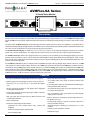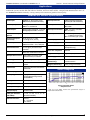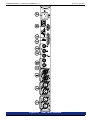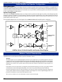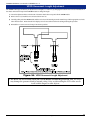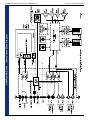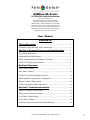
1
AVMFlex-SA Series
1U CVBS/SDI Audio/Video Monitor
Document P/N 821624 Rev-A
Two Analog Audio Inputs on XLRs, CVBS Video
Input/Loop on BNCs, SDI Input and Re-Clocked
Output on BNCs, Analog Audio Output (De-embedded
from SDI) on XLRs, Analog Audio Output of Selected
Source on two XLRs, Two 10-Segment Bargraph Level
Meters, SDI Lock Indication LED, and Video Display
Module Mounted on a Flexible Gooseneck
User Manual
CONTENTS
Title and Contents ....................................................................... 1
Introduction and Important Safety Instructions ...................................... 2
Section 1: General Features and Specifications .......... 3
Description and Features .......................................................................... 4
Applications and Specifications ............................................................... 5
Model Configurations and Naming Convention ..................................... 6
VPOD LCD Display Specifications ........................................................ 6
Section 2: Operation ................................................................... 7
Front Panel Features .............................................................................. 8
Rear Panel Features ............................................................................... 12
VPOD-5W On-Screen Display Controls ................................................ 16
Audio Amplifier and Speaker Configuration ......................................... 18
Balance Control Characteristics .............................................................. 18
VPOD Gooseneck Length Adjustment ................................................... 19
Section 3: Technical Information ......................................... 21
General Technical Observations ............................................................ 22
Tally Control Connector Wiring ............................................................ 23
Level Meter Specifications ..................................................................... 25
Level Meter Settings .............................................................................. 25
AVMFlex-SA Series Interconnect Block Diagram .................................. 26
© 2005 PANORAMAdtv ALL rights reserved
1
Important Safety Instructions
1)
Read these instructions.
2)
Keep these instructions.
3)
Heed all warnings.
4)
Follow all instructions.
5)
Do not use this apparatus near water.
6)
Clean only with dry cloth.
7)
Do not block any ventilation openings. Install in accordance with the manufacturer's instructions.
8)
Do not install near any heat source such as radiators, heat registers, stoves, or other apparatus (including
amplifiers) that produce heat.
9)
Do not defeat the safety purpose of the polarized or grounding-type plug. A polarized plug has two blades
with one wider than the other. A grounding type plug has two blades and a third grounding prong. The
wide blade or the third prong are provided for your safety. If the provided plug does not fit into your outlet,
consult an electrician for replacement of the obsolete outlet.
10) Protect the power cord from being walked on or pinched, particularly at plugs convenience receptacles
and the point where they exit from the apparatus.
11) Only use attachments/accessories specified by the manufacturer.
12) Use only with the cart stand, tripod, bracket, or table specified by the manufacturer, or sold with the
apparatus. When a cart is used, use caution when moving the cart/apparatus combination to avoid injury
from tip-over.
13) Unplug this apparatus during lightning storms or when unused for long periods of time.
14) Refer all servicing to qualified service personnel. Servicing is required when the apparatus has been
damaged in any way, such as when power-supply cord or plug is damaged, liquid has been spilled or
objects have fallen into the apparatus, the apparatus has been exposed to rain or moisture, does not
operate normally, or has been dropped.
15) Do not expose this apparatus to rain or moisture.
16) The apparatus shall be connected to a mains socket outlet with a protective earthing connection.
CAUTION!
In products featuring an audio amplifier and speakers, the surface at the side of the
unit, where the audio amplifier heat sink is internally attached, may get very hot after
extended operation. When operating the unit excercise caution when touching this
surface and ensure that external materials which may be adversely affected by heat
are not in contact with it. There is a Hot Surface label (see diagram) attached to the
aforementioned surface of the product.
Introduction
Congratulations on your selection of a PANORAMAdtv product. We are confident it represents the best performance and value
available, and we guarantee your satisfaction with it.
If you have questions or comments you may contact us at:
Wohler Technologies, Inc.
31055 Huntwood Avenue
Hayward, CA 94544
Phone: (510) 870-0810
Fax: (510) 870-0811
US Toll-Free: 1-888-596-4537
www.panoramadtv.com
2
[email protected]
© 2007 Wohler Technologies, Inc. ALL rights reserved
AVMFlex-SA Series User Manual P/N 821624 Rev-A
Section 1
General Features
and Specifications
Description
Features
Applications
AVMFlex-SA General Specifications
Model Configurations and Naming Convention
VPOD LCD Video Display Specifications
VPOD LCD Video
Installation
Unpacking
Unpack the AVMFlex-SA Series unit from the shipping container and inspect all articles for shipping damage. If you find any damage,
notify the shipping carrier immediately for claims adjustments. Compare the shipping box contents to the packing slip. Contact a
PANORAMAdtv sales representative if there are any unexplained shortages.
Heat Dissipation
Heat dissipated by the speaker amps is conducted directly to the left side of the chassis; no special considerations for cooling are
necessary as long as the ambient temperature inside the rack area does not exceed approximately 40°C (104°F).
Sympathetic Vibration
Sympathetic vibration from other equipment (cables, etc.,) in the rack may be serious enough to interfere with the unit’s sound
quality out in the listening area. The use of thin card stock and/or felt or foam weather-stripping type materials between adjacent
vibrating surfaces, or tying up loose cables, etc., may be required to stop vibrations external to the unit.
Audio Connections
Connection of the audio feeds is straightforward. Please refer to the system interconnect block diagrams on page 26 for clarification of
the general signal paths into and out of the AVMFlex-SA Series units.
Rack Mounting
The AVMFlex-SA Series unit rack mounts in a standard EIA-310-D specification 19”/483mm rack and needs 1RU of space. Allow
sufficient space at the unit rear for connector and cable clearance (approximately 4”/102 mm). The AVMFlex-SA Series unit rack mounts
from the front panel support rails. Rear support is not required.
Cable Recommendation
Recommended cable type for analog video signals is: Belden 8281, Belden 1694A, or equivalent.
Recommended cable type for analog audio signals is: Belden 9451 or equivalent.
© 2005 PANORAMAdtv ALL rights reserved
3
Section 1: General Features and Specifications
AVMFlex-SA Series User Manual P/N 821624 Rev-A
AVMFlex-SA Series
1U Audio/Video Monitor
AVMFlex-SA/4 Front Panel
Description
The AVMFlex-SA Series of audio/video monitors provides the capability to monitor CVBS (composite analog) or SDI (serial digital
interface) video on an LCD display with full-fidelity stereo audio monitoring in a single rack space (1U). The AVMFlex-SA Series models
feature a VPOD LCD video display module mounted to the front panel via a flexible gooseneck allowing for extensive control of the viewing
angle.
All models in the AVMFlex-SA Series contain four high performance speakers driven by three power amplifiers: two amplifier/driver
combinations handle midrange and high frequency information in stereo, while the third center channel reproduces information below the 500
Hz crossover point. Output limiter circuits are incorporated to protect the speakers.
The VPOD LCD Video Display is available in 4", 5.6", 5.8" (16:9), 6.8", and 7" (16:9) LCD sizes and features controls for color, tint/hue
(NTSC only), contrast, and brightness. The display also has a power LED of its own and a bi-color (red/green) tally indication LED.
All AVMFlex-SA Series models come equipped with two 10-segment tri-color (red/amber/green) LED bargraph display level meters,
separate volume and balance controls, a power indication LED, headphone output, and an SDI lock status LED display, which visually
shows the lock status of SDI signals selected for monitoring. Extensive magnetic shielding allows placement immediately adjacent to video
monitors with no color impurities.
The AVMFlex-SA Series rear panel is configured with one CVBS video input with loop-through output on BNC connectors, one SDI
video input and re-clocked output on BNC connectors, one CVBS video output de-embedded from the SDI input on a BNC connector,
two balanced (stereo) analog audio inputs on XLR connectors, two balanced analog audio outputs de-embedded from the SDI audio
input on XLR connectors, and two analog outputs of the selected audio source on two male XLR connectors. The audio and video inputs
are relayed so that selecting either the CVBS or SDI video source on the VPOD video display module will also select the associated CVBS
or SDI audio source. A DB-25 connector is also provided for tally connections.
Features
• Bi-amp sum amplification through high/mid and woofer speakers
• Relatively large LCD video display in a space-saving 1U rack size
• Choice of 4", 5.6", 5.8" (16:9), 6.8", or 7" (16:9) LCD video display
sizes
• Flexible gooseneck mounting of video display allows adjustable
viewing angle in all directions
• CVBS video inputs and loop-through output on BNC connectors
with selectable termination
• SDI video input and re-clocked output on BNC connectors with
selectable gain calibration
• SDI lock status LED
• VPOD LCD video display modules feature:
*Adjustment for color, tint/hue (NTSC only), contrast, and
brightness
*Dual color (red/green) talley indication LED
• NTSC/PAL format auto-sensing
• Two analog audio stereo inputs on balanced female XLR
connectors
• Two analog audio outputs de-embedded from the SDI input on
balanced female XLR connectors
• Two balanced analog ouputs of the selected audio source on
two female XLR connectors
• Two 10-segment tri-color (green/amber/red) LED bargraph
display audio level meters
• DB-25 connector on rear panel provided for tally connections
• 98 dB SPL at two feet
• Excellent high frequency response for positive detection of
background whine and noise
• Thorough magnetic shielding for placement next to video
monitors
• Separate volume and balance controls
• Headphone output
*Power indication LED
4
© 2005 PANORAMAdtv ALL rights reserved
Section 1: General Features and Specifications
AVMFlex-SA Series User Manual P/N 821624 Rev-A
Applications
The AVMFlex-SA Series is ideally suited for use in VTR bays, mobile production vehicles, teleconferencing installations,
multimedia systems, satellite link and cable TV facilities, and on-air radio studios. Designed and manufactured in the U.S.,
the AVMFlex-SA Series is backed by a strong warranty and a satisfaction guaranteed return policy.
AVMFlex-SA General Specifications
Audio Inputs:
Analog: x2 XLR (female, 3-pin)
SDI: x1 BNC (embedded with video)
Video Input Format:
CVBS (Composite Analog) video
SDI video (with audio embedded)
Audio Input Impedance:
Analog: >40k Ω, balanced
SDI: 75 Ω, unbalanced
Video Input Connectors:
CVBS: x1 BNC
SDI: x1 BNC
Audio Outputs:
Analog Output of Selected: x2 XLR-M
Analog Output from SDI: x2 XLR-M
Video Input Termination:
CVBS: 75 Ω (Ohm), selectable
SDI: 75 Ω (Ohm)
Peak Acoustic Output
@2 feet:
98dB SPL
Video Output Connectors:
CVBS: x1 BNC (passive loop-thru)
x1 BNC (from SDI Input)
SDI: x1 re-clocked (regen.) output
Frequency Response
(1/6 Octave):
80 Hz to 20 Hz (+/- 5 dB)
(-10 dB @ 50 Hz, 22 kHz)
Video Display Modes:
NTSC/PAL autosensing
Power Output:
RMS each side = 5W, 7W peak
RMS dual woofer = 11W, 16W peak
Video Display Type:
Active Matrix TFT-LCD
Video Picture Controls:
Electrical Distortion:
<0.15% @ any level below input
threshold
Brightness, contrast, color,
and tint (NTSC only)
Video Color Configuration:
RGB delta
Hum and Noise:
Better than -68 dB below full output
Magnetic Shielding:
<1 gauss any adjacent surface
Power Supply:
Internal 100 to 240 VAC, 50-60 Hz
SDI Input Characteristics: 75 Ohm (BNC), AC coupled, 15 dB
minimum return loss, 10-270 MHz
Receiver type:
Auto equalizing with clock regeneration
Dimension (h x w x d)
(chassis only):
1.75 x 19 x 10 inches
44.5x 483 x 254 mm
Sensitivity performance:
Tolerates cable loss of at least 30 dB @
135 MHz
Weight (chassis only):
9.5 lbs. (4.3 kg) w/ 6.8 VPOD
Input formats:
Component, either 525 or 625 lines w/
48 KHz audio
Audio sampling rate:
48 KHz
SDI output type:
Fully regenerated copy of SDI input
signal (equalized and regenerated,
scrambled NRZI)
Audio Response
+10
0
d
B
-10
-20
SDI output:
400 - 700 ps
-30
20
50
100
200
500
1k
2k
5k
10k
20k
Hz
SDI output level:
750 - 850 mv
Max. output of analog out:
+24 dBv (0 dBv = 0.775 vRMS)
THD (full output):
Less than 0.008%
D to A gain calibration,
(dB = dBFS):
+8 = -20, +4 = -20, +6 = -9, 0 = -18
(DIP switch selectable)
SDI Lock Indication:
Red LED,
Off = not locked
Red = locked
Typical 1/6 Octave Audio
Response Curve
0 dbu ref. 0.775V RMS. Features and specifications subject to
improvement without notice.
© 2005 PANORAMAdtv ALL rights reserved
5
Section 1: General Features and Specifications
AVMFlex-SA Series User Manual P/N 821624 Rev-A
Model Configurations and Naming Convention
The only difference between the various models of AVMFlex-SA Series is the size of the LCD video display used in the specified
VPOD LCD display module.
Model
VPOD Model Display Size
AVMFlex4-SA
VPOD4
4"
AVMFlex5-SA
VPOD5
5.6"
VPOD5W
5.8" (16 x 9)
VPOD6
6.8"
VPOD7W
7" (16 x 9)
AVMFlex5W-SA
AVMFlex6-SA
AVMFlex7W-SA
VPOD LCD Video Display Specifications
VPOD Video Specs:
VPOD4
VPOD5
VPOD5W
VPOD6
VPOD7W
4"
5.6"
5.8"
6.8"
7"
82.1 x 61.8
113.3 x 84.7
127.2 x 71.84
138.2 x 103.4
154.1 x 88.6
4:3
4:3
16:9
4:3
16:9
480 x 234
960 x 234
1200 x 234
1152 x 234
1440 x 234
Dot Pitch (mm):
0.171 x 0.264
0.118 x 0.362
0.106 x 0.307
0.120 x 0.442
0.107 x 0.370
Contrast Ratio:
150 : 1
150 : 1
150 : 1
150 : 1
150 : 1
250
300
400
300
400
10 / 30 / 45 / 45
10 / 30 / 45 / 45
30 / 60 / 60 / 60
10 / 30 / 45 / 45
60 / 30 / 60 / 60
0.9 lbs.
1 lbs.
1.25 lbs.
1.3 lbs.
1.4 lbs.
3W
7W
7W
8W
10W
3.45 x 4.92 x 1.1
4.15 x 6.4 x 1.22
4.23 x 6.4 x 1.22
5.18 x 7.5 x 1.22
4.93 x 7.4 x 1.22
Screen Size (diagonal inches ):
Active Area (H x V, mm):
LCD Aspect Ratio:
Resolution (dots x lines):
Brightness (NITs):
Viewing Angle (top/bottom/left/right):
Weight (VPOD module w/mount):
Power Consumption (Watts, VPOD):
Height x Width x Depth (inches):
6
© 2005 PANORAMAdtv ALL rights reserved
AVMFlex-SA Series User Manual P/N 821624 Rev-A
Section 2
Operation
Front Panel Features
Rear Panel Features
VPOD-5W On-Screen Display Controls
Audio Amplifier and Speaker Configuration
Balance Control Characteristics
VPOD Gooseneck Length adjustment
© 2005 PANORAMAdtv ALL rights reserved
7
AVMFlex-SA Series User Manual P/N 821624 Rev-A
Section 2: Operation
Front Panel Features
Please refer to Figure-2a on the facing page to familiarize yourself with the front panel features of the AVMFlex-SA Series unit. The
following sections describe these functions and are referenced, by number, to Figure-2a.
1
Speakers
The internal speaker system is comprised of two mid-range tweeter speakers (left and right) and two woofer speakers (left
and right). The two mid-range speakers reproduce only the mid and high frequencies, while the two woofer speakers
monaurally reproduce the low frequencies. See page 18 for more information about the audio amp and speaker configuration.
2
Headphone Output Jack
This jack accepts a standard 1/4” phone type stereo plug. Select the headphone audio sources as you would for the internal
speakers. When you plug in headphones, the speakers will mute.
3
SDI Group Select Switch
This 8-position rotary switch is used to select the SDI Group (G1, G2, G3, or G4) and SDI Subgroups (1, 2 or 3, 4) for
the SDI source. The SDI source is selected using the A/B Select switch (Item 4, page 10) on the front of the VPOD LCD
display pod.
4
Audio Level Meters
Audio levels are visually displayed via these two 10-segment, tri-color (RED, AMBER, GREEN) LED bargraph display level
meters. The bargraph on the left indicates left channel audio levels of the of the selected source, while the bargraph on the
right indicates right channel audio levels. These meters are able to display signal levels using either PPM or VU standards as
selected via a DIP switch module accessible by removing the top cover of the unit. See page 25 for specifications and
settings of these meters.
5
Volume Control
This controls the loudness of the audio reproduced by the internal speakers or connected headphone. Clock-wise rotation
of this control increases the loudness of the monitored audio in both channels (left and right).
6
VPOD LCD Video Display Module
Video signals entering the AVMFlex-SA Series unit are monitored through the VPOD LCD video display. The VPOD
module is attached to the front panel by a length of flexible gooseneck tubing allowing angle viewing adjustment in all
directions. One of five sizes of LCD display screens may be specified, including 4", 5.6", 5.8" (16:9), 6.8", and 7" (16:9)
LCD display sizes.
See page 10 for complete information on the use and control of the VPOD LCD video display module.
7
Balance Control
This adjusts the volume balance between the left and right speakers. See page 18 for a description of the AVMFlex-SA
balance control characteristics.
8
© 2005 PANORAMAdtv ALL rights reserved
AVMFlex-SA Series User Manual P/N 821624 Rev-A
Section 2: Operation
Figure-2a: Front Panel Features
© 2005 PANORAMAdtv ALL rights reserved
9
AVMFlex-SA Series User Manual P/N 821624 Rev-A
Section 2: Operation
Front Panel Features
Please refer to Figure-2b on the facing page to familiarize yourself with the front panel features of the VPOD LCD display modules that can
be specified for the AVMFlex-SA Series units. The following sections describe these features and are referenced, by number, to Figure2b. The AVMFlex-SA 1U front panel, to which these displays are installed, is described and illustrated on pages 8 and 9.
VPOD - LCD Video Display Modules
Each VPOD LCD video display module houses the LCD Video Display Screen, Display Controls, A/B Input Select Switch,
Tally Indication LED, and Power Indication LED. Each VPOD module is attached to the AVMFlex-SA front panel by a length
of flexible gooseneck tubing. AVMFlex-SA Series units are manufactured with a VPOD module permanently attached to the front
panel. Five sizes of LCD display screens are available for the AVMFlex-SA Series; 4", 5.6", 5.8" (16:9), 6.8", and 7" (16:9).
The VPOD module may be adjusted for viewing angle independant of the fixed position of the main chassis. There is about a +/- 60
degree field of movement of the VPOD module from the vertical and horizontal plane of the front panel. When adjusting the angle of
the video screen, grasp the VPOD module at the right/left or top/bottom sides. Care should be taken not to touch the LCD video
screen itself with the fingers or other objects.
CAUTION: Do NOT rotate (twist) the VPOD module around the gooseneck axis; the torque may
damage the gooseneck and/or internal wiring. Also, avoid touching the LCD video screen itself with
the fingers or other objects.
NOTE: The 5.8" VPOD (VPOD5W), unlike the other VPOD models, features on-screen controls. See page 16 for
descriptions of these controls and their use.
1
Tally Indication LED
This tri-color LED can glow RED, GREEN, or YELLOW to indicate tally status associated with the video signal displayed.
Refer to page 23 for tally connection details.
2
Display Controls
The displayed video image for each VPOD LCD display module may be separately adjusted using these four image controls:
• TNT = Tint; adjust for desired image color hue (NTSC only).
• COL = Color Saturation; adjust for desired amount of image color saturation.
• BRT = Brightness; adjust for desired screen brightness.
• CNT = Contrast; adjust for desired image scene, dark-to-bright contrast.
NOTE: The 5.8" VPOD (VPOD5W) display module instead uses on-screen controls as described in Item 6.
3
LCD Video Display
Selected video sources are displayed here. Screen image parameters are adjustable by four manual controls (Item 2). See
page 6 for LCD display specifications.
4
A/B Input Select Switch (CVBS or SDI)
This switch selects between the CVBS video input (and Analog audio input) and SDI video input (Item E, page 12)
sources. The audio sources are relayed to the video selection. The A/B Input Select Switch selects the video and audio
source signals according to the following switch positions:
• Position "A": SDI video input with embedded audio (Item E, page 12).
• Position "B": CVBS video input (Item G, page 12) and Balanced Analog Audio Input (Item J, page 14).
5
Power Indication LED
This LED glows GREEN to indicate the unit is connected to mains power and an operation voltage is present.
6
VPOD5W On-Screen Display Controls (AVMFlex-SA/5W Only)
Display controls for the 5.8" VPOD (VPOD5W) are set via these three buttons. Parameters are manipulated as
described on page 16.
10
© 2005 PANORAMAdtv ALL rights reserved
AVMFlex-SA Series User Manual P/N 821624 Rev-A
Section 2: Operation
Figure-2b: Front Panel Features
© 2005 PANORAMAdtv ALL rights reserved
11
AVMFlex-SA Series User Manual P/N 821624 Rev-A
Section 2: Operation
Rear Panel Features
Please refer to Figure-2c on the facing page to familiarize yourself with the rear panel features of the AVMFlex-SA Series units. The
following sections describe these features and are referenced, by letter, to Figure-2c.
A
Power Connector
Attach the supplied standard IEC-320 power cord between this connector and mains power (100 - 250VAC, 50/60 Hz).
B
RS232 Connector
This connector is used for uploading revision data into the 910935 Audio/Video demux PCB.
C
Tally Connector
This 25 pin sub-miniature female “D” connector (TALLY) allows you to tally the Tally Indication LED (Item 1, page 10).
Connection details are described on page 23.
D
SDI Digital Gain Calibration DIP Switch
SDI input Digital Gain Calibration, the analog level which corresponds to a given digital input value, is settable via this 2position DIP switch module. The factory setting is +4 dB (analog) = -20 dBFS (digital). See the silk-screened chart on the
rear panel or the diagram below for settings.
E
SDI Input and Output Connectors
The SDI IN female BNC connector is meant to receive standard audio/video embedded SDI signals and is configured for an
unbalanced 75 Ω connection. Use the SDI Group Select Switch (Item 3, page 8) to choose the SDI Group and Subgroups
to monitor. To monitor this input, the A/B Select Switch (Item 4, page 10) on the VPOD module must be set to A.
The SDI OUT female BNC connector outputs a reclocked (regenerated) copy of the signal entering the SDI IN input
connector and is configured for an unbalanced 75 Ω connection. This output functions regardless of other selection settings.
This feature enables output of the re-clocked SDI signal independant of the units other monitoring functions (as long as a
valid SDI source is present at the SDI IN input connector).
F
CVBS Video Ouput (From SDI Input)
The SDI CVBS OUT female BNC connector outputs CVBS (composite analog) video signals de-embedded from the SDI
bitstream entering the SDI IN input connector (Item E).
This output functions regardless of other selection settings. This feature enables de-embedding of the SDI signal to CVBS
independant of the units other monitoring functions (as long as a valid SDI source is present at the SDI IN input connector).
G
CVBS Video Input and Loop-Through Connectors
The CVBS IN female BNC connector accepts standard CVBS (composite analog) video signals and is configured for 75 Ω
impedance connections. To monitor this input, the A/B Select Switch (Item 4, page 10) on the VPOD module must be set
to B. Note that the Balanced Analog Audio Input Connectors (Item J, page 14) are relayed to the CVBS input selection,
and so are automatically selected for audio monitoring when the CVBS video input source is selected for video monitoring.
The CVBS LOOP female BNC connector provides passive signal-through connections from the CVBS IN connector to
down-stream equipment. See Item H for information about setting the termination for these connectors. Note that these
outputs function even if power to the AVMFlex-SA unit is turned OFF.
H
CVBS Input Temination Switch
The LIFT/TERM slide switch is used to set the termination for the CVBS input. If the CVBS LOOP connector (Item G)
is connected to downstream equipment, un-terminate by setting the switch to the DOWN position (LIFT). If no
downstream equipment is connected, terminate by setting the switch to the UP position (TERM).
(Continued)
12
© 2005 PANORAMAdtv ALL rights reserved
AVMFlex-SA Series User Manual P/N 821624 Rev-A
Section 2: Operation
Figure-2c: Rear Panel Features
© 2005 PANORAMAdtv ALL rights reserved
13
Section 2: Operation
AVMFlex-SA Series User Manual P/N 821624 Rev-A
Rear Panel Features
(Continued)
I
Analog Audio Output (From SDI Input) Connectors (LEFT and RIGHT)
The ANALOG AUDIO OUT FROM SDI 3-pin male XLR connectors (LEFT and RIGHT) output analog audio signals
de-embedded from the SDI bitstream entering the SDI IN Connector (Item E, page 12). See the diagram under Item K for
pinout information for these connectors.
J
Balanced Analog Audio Input Connectors (LEFT and RIGHT)
The BALANCED AUDIO INPUT 3-pin female XLR connectors (LEFT and RIGHT) accept standard analog audio
signals and are configured for balanced 40K Ω impedance connections. Note that these inputs are relayed to the CVBS
input selection, and so are automatically selected for audio monitoring when the CVBS video input source is selected for
video monitoring (see Item 4, page 10). See the diagram under Item K for pinout information for these connectors.
K
Selected Balanced Analog Audio Output Connectors (LEFT and RIGHT)
The SELECTED BALANCED ANALOG AUDIO OUTPUT 3-pin male XLR connectors are analog outputs of the audio
source as selected for the left and right speakers. See the diagram below for pinout information for these connectors.
Pin-2
High (+)
14
Pin-1
Gnd
(Shield)
Pin-1
Gnd
(Shield)
Pin-2
High (+)
Pin-3
Low (-)
Pin-3
Low (-)
Female XLR Pinout
Male XLR Pinout
© 2005 PANORAMAdtv ALL rights reserved
Section 2: Operation
AVMFlex-SA Series User Manual P/N 821624 Rev-A
Figure-2c:
Rear Panel Features
© 2005 PANORAMAdtv ALL rights reserved
15
Section 2: Operation
AVMFlex-SA Series User Manual P/N 821624 Rev-A
VPOD5W On-Screen Display Controls (AVMFlex-SA/5W2 Only)
Display controls for the 5.8" VPOD (VPOD5W) are set via the three buttons on the VPOD front panel (See Item 6, page 10).
Parameters are manipulated as described below:
BRIGHTNESS
Press the UP and DOWN buttons directly to increase and decrease the LCD display BRIGHTNESS. The image below
will be displayed on-screen while adjusting to indicate the level.
BRIGHT
COLOR / CONTRAST / TINT
1) Press the MENU button to access the Main Menu onscreen.
2) Press the UP and DOWN buttons to scroll through the options.
3) Press the MENU button to select the chosen parameter for adjustment.
4) Press the UP and DOWN buttons to adjust the level.
5) Press the MENU button to return to the Main Menu.
6) To exit the menu, use the UP and DOWN buttons to select EXIT and then press MENU.
NOTE: The TINT parameter is applicable ONLY when monitoring NTSC video source signals.
The onscreen menu and pamameters for COLOR, CONTRAST, and TINT controls are shown below:
COLOR
Adjustment:
CONTRAST
Adjustment:
TINT
Adjustment:
BRIGHT
COLOR
CONTRAST
TINT [NTSC ONLY]
SYSTEM SETUP
EXIT
COLOR
G
R
B
BRIGHT
COLOR
CONTRAST
TINT [NTSC ONLY]
SYSTEM SETUP
EXIT
BRIGHT
COLOR
CONTRAST
TINT [NTSC ONLY]
SYSTEM SETUP
EXIT
(Continued)
16
© 2005 PANORAMAdtv ALL rights reserved
CONTRAST
TINT
Section 2: Operatio
AVMFlex-SA Series User Manual P/N 821624 Rev-A
VPOD5W On-Screen Display Controls (AVMFlex-SA/5W Only)
(Continued)
SYSTEM SETUP
To enter the System Setup submenu, choose SYSTEM SETUP in the Main Menu, and press the MENU button.
Main Menu:
BRIGHT
COLOR
CONTRAST
TINT [NTSC ONLY]
SYSTEM SETUP
EXIT
System Setup Menu:
DIMMER 8
POWER SAVING ON
FSC SET 3.58MHz
TINT [NTSC ONLY]
HOR. NOR
VER. NOR.
MODE NORMAL
EXIT
Use the UP and DOWN buttons to select System Setup option as shown below.
DIMMER (1-8)
1) Press MENU button to select DIMMER option.
2) Press Up and DOWN buttons to select Dimmer level from 0 to 8.
3) Press MENU to activate selection.
This adjusts the LCD backlight brightness level.
POWER SAVING ON
1) Press MENU button to select POWER SAVING ON option.
2) Press Up and DOWN buttons to select POWER SAVING ON or POWER SAVING OFF.
3) Press MENU to activate selection.
When the display is set up with Power Saving Mode ON, power will automatically turn off after 6 seconds
if there is no video signal entering the display. Power will automatically turn as soon as a video signal is
detected.
FSC SET 3.5MHz
1) Press MENU button to select FSC SET 3.5MHz (Frequency Subcarrier) option.
2) Press Up and DOWN buttons to select FSC SET 3.58MHz or FSC SET 4.43MHz.
3) Press MENU to activate selection.
This option will force the Frequency Subcarrier of the display at 3.58MHz or 4.43 MHz.
HOR. NOR.
1) Press MENU button to select HOR. NOR. (Horizontal Reverse Image) option.
2) Press Up and DOWN buttons to reverse the image horizontally.
3) Press MENU to activate selection.
VER. NOR.
1) Press MENU button to select VER. NOR. (Vertical Reverse Image) option.
2) Press Up and DOWN buttons to reverse the image vertically.
3) Press MENU to activate selection.
MODE NORMAL
1) Press MENU button to select MODE NORMAL option.
2) Press Up and DOWN buttons to select NORMAL, ZOOM1, or FULL.
3) Press MENU to activate selection.
NORMAL mode will display images in original aspect ratio of source (example: 4:3 ratio displayed
undistorted in 16:9 screen with blank space on either side). ZOOM1 mode zooms into center area of
display. FULL mode forces aspect ratio of source to conform to 16:9 aspect ratio (example: 4:3 ratio
displayed in 16:9 screen stretched [distorted] to fill entire display).
EXIT
Press MENU button to select EXIT option, press MENU button again to return to Main Menu.
© 2005 PANORAMAdtv ALL rights reserved
17
Section 2: Operation
AVMFlex-SA Series User Manual P/N 821624 Rev-A
Audio Amplifier and Speaker Configuration
General Description
All AVMFlex-SA Series modals contain high performance transducers (speakers) driven by three power amplifiers; two amplifier/driver
combinations handle midrange and high frequency information in the left and right (stereo) speaker channels, while the third amplifier channel
sums the left and right channel information below the 500 Hz crossover point in the woofer (bass) speaker(s). Note that the woofer channel
is NOT a dedicated LFE or Center channel.
Speaker Configuration
The 1U rack size AVMFlex-SA Series products are configured with two speakers (left and right) to reproduce mid- and high-range audio
frequencies (in stereo), but feature two woofer speakers to reproduce the summed (combined) low-range audio frequencies from the left
and right speaker input channels. It should be noted that both woofer speakers, which are wired in series, are driven from one woofer
speaker channel, and are NOT stereo.
See the simplified diagram below for a block diagram of the AVMFlex-SA Series audio amplifier/speaker configuration.
Left
Speaker
Input A
(Left)
EQ
Limiter
High-Pass
Left Speaker
Channel
Amplifier A
Woofer
Speaker
Volume/
Balance
(VCO)
Lo-Freq
Amplifier
Sum
Low-Pass
Limiter
Input B
(Right)
Woofer Speaker
Channel
Woofer
Speaker
Right
Speaker
EQ
Limiter
High-Pass
Right Speaker
Channel
Amplifier B
AVMFlex Series (1U) Audio Amplifier and Speaker Block Diagram
Balance Control Characteristics
The balance control attenuates the signal from the source, so that the left and right bass frequencies (summed together and
reproduced in the woofer channel) will also respond to the balance control.
Example:
If an audio signal of a voice speaking English is fed to the left (A) input and a voice speaking Spanish is fed to the
right (B) input, then the left speaker channel will reproduce the midrange and high-range frequencies of the English
speaking voice, the right speaker channel will reproduce the midrange and high-range frequencies of the Spanish
speaking voice, and the woofer speaker channel will reproduce the summed (combined) low-range frequencies of
both voices.
If the balance control is rotated to the left (English), then the Spanish speaking voice in the right speaker channel
will diminish in volume and the Spanish speaking voice in the woofer speaker channel will also diminish.
Note that if the balance control is rotated completely to the left, the volume in both the left speaker channel and
woofer speaker channel will increase slightly to maintain overall output level. See the simplified diagram above for
placement of the balance control in the audio amplifier circuit.
The converse of the above is true if the balance control is rotated to the right.
18
© 2005 PANORAMAdtv ALL rights reserved
AVMFlex-SA Series User Manual P/N 821624 Rev-A
VPOD Gooseneck Length Adjustment
The VPOD LCD display module may be adjusted for two lengths (1.3" and 2.25") by changing the location of two screws on the bottom of
the chassis which are lined up with the VPOD module. To change the length:
1) Locate the adjustment holes on the bottom of the main chassis that correspond with the VPOD module.
2) Remove the two (2) installed screws and set aside for later use.
3) Carefully pull or push the VPOD module until the two holes of the internal gooseneck mount line up with the appropriate two holes
in the chassis bottom. Ensure that the LCD display screen is not touched or otherwise damaged during this operation.
4) Reinstall the two screws removed in step 2 into the new position.
Figure-3d: VPOD Gooseneck Length Adjustment
CAUTION: Do NOT rotate (twist) the VPOD module around the gooseneck axis; the torque
may damage the gooseneck and/or internal wiring. Also, avoid touching the LCD video screen
itself with the fingers or other objects.
© 2005 PANORAMAdtv ALL rights reserved
19
AVMFlex-SA Series User Manual P/N 821624 Rev-A
(This page left intentionally blank)
20
© 2005 PANORAMAdtv ALL rights reserved
AVMFlex-SA Series User Manual P/N 821624 Rev-A
Section 3
Technical Information
Tally Control Connector Wiring
Level Meter Specifications
Level Meter Settings
AVMFlex-SA Series Interconnect Block Diagram
© 2005 PANORAMAdtv ALL rights reserved
21
AVMFlex-SA Series User Manual P/N 821624 Rev-A
Section 3: Technical Information
General Technical Observations
General Mechanical Observations
Elimination of cabinet and component sympathetic vibrations (resonances) requires considerable attention to mechanical details. Because
of this, and the physical constraints of the speaker’s acoustic enclosures, even minor changes to any of the mechanical details of the unit
can seriously impair its acoustic performance. This especially applies to the speaker baffles. If mechanical work on the unit is necessary,
be sure to make adequate notes to permit accurate reassembly.
Unfortunately, the unusual and wholly proprietary method of magnetic shielding is usually degraded slightly by any disassembly of the
unit, except removal of the rear panel. Almost any maintenance or repair will require removal of the cover. If an immediately adjacent
video monitor shows magnetic interference after reassembly of the unit, it must be returned to the factory to restore the shielding
completely.
General Audio Circuitry Observations
Since a single-sided power supply is used, all amplifier sections are “biased” with a 1/2 supply reference, so all opamp signal terminals on
the main board should have a DC level of +12V, +/-0.7V. Signal inputs to the main audio board from any of the input select circuits are
via the balanced input stage, in lieu of the XLR analog inputs on the basic unit. Signal feed points for level meters and the phase indicator
are immediately after the input stage, and before the volume control section.
The signal pick-off for the headphones is after the volume and balance controls. Speaker muting is controlled by circuitry that senses
connection of headphones to the jack.
The power amps are attached to an aluminum heatsink plate (which is also connected to the circuit common for these devices). The
heatsink plate forms an operational module separate from the chassis, which allows access to the solder side of the circuit board while
power is applied to the circuitry. To avoid thermal shutdown of the power amp(s), they should NOT be operated without their tabs
being fastened to the heatsink plate.
Variations in the frequency response of different production runs of drivers has sometimes required minor adjustments in the equalization/
crossover components in individual runs of units. Some of these components may have values slightly different than those indicated in
the schematic, which are the nominal ones. If any of the drivers (speakers) are replaced, it may be helpful to change some of these
components to achieve maximum flatness of response.
The operating threshold of the woofer limiter is critical to both satisfactory reproduction of musical transients and preventing damage to,
or destruction of, the speaker itself. The side speaker output limiter circuits are similarly important, though not as critically adjusted.
The woofer power amps are arranged in a bridge configuration; care must be taken to avoid letting EITHER speaker terminal contact the
chassis (common) OR THE GROUNDED LEAD OF ANY TEST EQUIPMENT so as not to short out the power amps. The side
speaker outputs are single-ended, so these precautions are not necessary for them.
22
© 2005 PANORAMAdtv ALL rights reserved
AVMFlex-SA Series User Manual P/N 821624 Rev-A
Section 3: Technical Information
Tally Control Connector Wiring
A front panel dual-color Tally Indication LED is associated with each LCD display module. Interface is provided to the LEDs via
the Tally Control Connector located on the chassis rear panel. The Tally Indicator LEDs are capable of displaying three colors;
RED, GREEN, and AMBER. Illuminating the RED or GREEN LEDs separately will result in that tally color. Illuminate the RED and
GREEN LEDs simultaneously to achieve a AMBER tally indication in the LED. For Tally Control Connector pinout functions, see
the diagram below.
Three examples of tally connection configurations are shown on the next page. You can operate the Tally Indication LEDs by
numerous methods. The three tutorial examples showing dry closure, positive true logic drive, and open collector activation are
illustrated to show basic operation. The LEDs interface with TTL levels. You can design illumination circuits as shown, by using
TTL buffers, or by using transistors as switches.
Note that since the AVMFlex-SA Series units feature only a single LCD display (and Tally LED), only the first tally channel is
utilized in the pinout diagram below and in the wiring examples on the next page.
Not connected for
AVMFlex-SA
Series units
Tally Connector Pin Functions
© 2005 PANORAMAdtv ALL rights reserved
23
AVMFlex-SA Series User Manual P/N 821624 Rev-A
Section 3: Technical Information
Tally Control Connector Wiring
Note that since the AVMFlex-SA Series units feature only a single LCD display (and Tally LED), only the first tally channel is
utilized in the wiring examples below.
N/C
N/C
N/C
Tally Connection Configuration Examples
24
© 2005 PANORAMAdtv ALL rights reserved
Section 3: Technical Information
AVMFlex-SA Series User Manual P/N 821624 Rev-A
Level Meter Specifications
Level Calibration:
-6, 0, +4, +8 dBv, Selectable
Frequency Response:
20 Hz to 18 kHz (±0.5 dB)
Level Meter Type:
10-segment LED Bargraph Display
LED Colors:
Tricolor (red, amber, green)
Metering Range:
23 dB
Display Mode (Ballistics):
VU or PPM, Selectable
VU Characteristics:
Rise Time =
300 millisecond to 99 % of full indication
Decay Time =
300 millisecond
PPM Characteristics:
Attack Time =
10 milliseconds
Decay Time =
2 seconds, 0 to -20 dB
Bargraph Length:
2.00" (50.8 mm)
LED Segment Size:
0.152" x 0.305" (3.56 x 7.75 mm)
LED Segment Pitch:
0.20" (5.08 mm)
Segment Brightness, (I f = 20 mA):
5.5 mcd
Segment Brightness, Uniformity:
<8% difference between segments
Adjacent Segment "Off" Brightness: <1% of brightness of active segment
Peak Emission Wavelength:
green: 570 nm red: 630 nm
Level Meter Settings
Level Meter DIP Switch Location
Two DIP switch modules allow the user to set the level meter parameters independently for each of the two bargraph displays. These
DIP switches are accessible by removing the top cover of the unit and are located on two PCBs installed at right angles to the front
panel where the level meters are installed. The DIP switches face upwards for easy adjustment.
There are four sections (1, 2, 3, 4) on each DIP switch module. The first two sections (1 and 2) are for setting the Meter Input
Gain Calibration and the second two sections (3 and 4) are for setting the Bargraph Display Mode.
Meter Input Gain Calibration Settings
DIP switch sections 1 and 2 set the Meter Input Gain Calibration, which determines the level of the input signal that will result in
a "0" reading on the meter bargraphs. The factory setting is +4 dBv, but can instead be set for -6 dBv, 0 dBv, or +8 dBv by the
user. See the diagram below for settings.
Bargraph Display Modes
DIP switch sections 3 and 4 determine how peak levels are displayed (Display Mode) and select either the PPM mode or an autoreset VU Peak mode (NOT the PPM value!). The PPM mode exhibits an attack time of 10 milliseconds and a decay time of 2
seconds from 0 to -20 dB. The VU mode exhibits a 300 millisecond rise to 99% of full indication and a decay of 300 milliseconds.
The factory setting is VU mode. See the diagram below for settings.
© 2005 PANORAMAdtv ALL rights reserved
25
AVMFlex-SA Series
Interconnect Block Diagram
AVMFlex-SA Series User Manual P/N 821624 Rev-A
26
© 2005 PANORAMAdtv ALL rights reserved
Section 3: Technical Information
AVMFlex-SA Series User Manual P/N 821624 Rev-A
Notes:
© 2005 PANORAMAdtv ALL rights reserved
27
AVMFlex-SA Series User Manual P/N 821624 Rev-A
PANORAMAdtv
Wohler
Technologies, Inc.
31055 Huntwood Avenue
31055Hayward,
Huntwood
Avenue
CA 94544
Hayward,
CA
94544
1-888-596-4537 Fax: (510) 870-0811
Phone: (510) 870-0810
Fax: (510) 870-0811
web: www.panoramadtv.com
US Toll-Free:
1-888-596-4537
e-mail:
[email protected]
www.panoramadtv.com [email protected]
28
© 2005 PANORAMAdtv ALL rights reserved