1
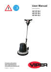
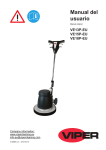
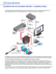
Installation Notes – Addendum PVS 204SA Plus PVS 204SA PLUS INPUTS ON PoleVault Switcher HIGH PASS FILTER CONFIG ™ STEREO ON 1 2 OFF AUTO SWITCH 1 RGB POLEVAULT SWITCHER 3 VIDEO 2 AUDIO 4 AUX/MIX LEVEL PAGING MIN/MAX DUAL MONO CLIP SENSITIVITY The Extron PVS 204SA is a four input, two output, twisted pair, audio and video switcher with a built in audio amplifier. The PVS 204SA accepts high resolution (RGB) video and audio, and composite video and audio signal inputs, along with a line level mono audio auxiliary/mix input. The PVS 204SA is part of the PoleVault System, and is used in conjunction with the Extron PVT series of transmitters and with Extron speakers. Installing the PVS 204SA Plus Mount the PVS 204SA Plus in the Extron PMK 450 (Projector Mount Kit), which is installed above the projector, as follows: 1. Follow steps 1 through 3 of “Installation — Stage Four”, in the PoleVault System Installation Manual, supplied with the complete PoleVault System. 2. Lift the PMK’s bottom plate (with the PVS 204SA Plus and power supply installed) up to the base of the pole, and connect the cables to the switcher as shown below. RGB output to projector Video output to projector VGA PVT RGB D Input (2 cables, A and B) RCA d b Audio output to speakers k e Wire colors (Left and Right) Red - Positive terminals Black - Negative terminals AUDIO IN RGB #1B COMPUTER IN 4-pole Captive Screw Connector RGB #1A CAT 5 cables with RJ-45 connectors 1A RGB N15779 2A RGB 3A RGB AMPLIFIED OUTPUT 4A RGB LISTED 17TT ® POWER 12V 3A MAX I N P U T S a 2B RGB RGB RGB 3B VIDEO 4B VIDEO N This power supply is sufficient to power the switcher, up to 4 A/V wallplates and the MLC 104 IP Plus controller Ground AUDIO IN L R Power source RS-232 MLC/IR Tx Rx IR 12V A B C D E 5-pole Captive Screw Connector VIDEO IN External Power Supply (12 VDC, 3 A max.) 4/8 Ohms L MLC104 IP Plus RS-232 input VIDEO #4 CAT 5 cable with RJ-45 connector Tie Wrap DO NOT GROUND OR SHORT SPEAKER OUTPUTS L PAGING AUX/MIX IN SENSOR R R VOL/MUTE 10V LINE OUT AUDIO DC VOL f PVT CV D Input (1 cable) 2-pole Captive Screw Connector +12 VDC input VIDEO UL 2043 PLENUM RATED c Power Supply APPARATUS CONTROL OUTPUTS RGB 1B RGB US AUDIO/VIDEO MLC Wire colors A (Rx) White B (Tx) Violet Ground Drain Wire Ground Black 12V In Red +12 VDC Ground ( ) Ground ( ) Receive (Rx) B Transmit (Tx) A gh 10V i j Sensor g Paging 2-pole Captive Screw Connector h Aux/Mix 3-pole Captive Screw Connector Line Out Audio i 5-pole Captive Screw Connector Volume Control (Vol/Mute) j DC3-pole Captive Screw Connector PVS 204SA A (Tx) B (Rx) D (Ground) D (Ground) E +12 V Power connection aDC power connector — Attach the supplied orange, 2-pole, male captive screw connector to the cord of the supplied power source as shown in the figure above. When all other cables have been connected, plug the captive screw connector into the 2-pole female connector to connect the switcher to the 12 VDC power source. The front panel power LED ( ) lights while the PVS is receiving power. N Use only the supplied 12 V power supply for this switcher. A/V input connections bRGB video and audio inputs (“RGB”) — Each RGB input requires the use of two twisted pair (TP) cables, A and B. Using TP cables, connect up to four high resolution computer video and audio sources via the PVT RGB D input wallplates to these eight RJ-45 female connectors. N Inputs 3 and 4 can be configured for either RGB or composite video signals via RS-232. Default is composite video. 1 Installation cComposite video and audio inputs (”Video”) — Each composite video input (3B and 4B) needs one TP cable. Using TP cable, connect up to two composite video and audio sources via the PVT CV D input wallplates to 3B and 4B RJ-45 female connectors. ™ C The PoleVault signal transmission method is specific for PVS 204SA Plus switchers working with PVT wallplates. DO NOT connect to an MTP system. DO NOT connect to an Ethernet/LAN or data transmission system. N Do not connect an RGB cable (cable A) to the top ports (3A and 4A) when connecting composite video cables to the lower ports (3B and 4B). The PVS 204SA Plus is capable of receiving signals from PVT wallplates located up to 100 feet (30 m) away. The optimum distance is between 50 and 75 feet (15 and 22 m). Cable A carries the video signals and cable B carries the audio signal, vertical sync information and 5 VDC current from the PVS to power the PVT wallplates. The ports on the rear of the PVS 204SA Plus are color coded for input number and signal type. To ensure correct cable identification and connection during installation, a sheet of color coded cable labels is supplied. Refer to “Labeling the A/V Inputs” section in the Polevault System Installation Manual, for details. When connecting the TP cables to the PVS 204SA Plus, do not cross-connect the cables; connect input 1’s cable A to the RJ-45 port labeled 1A, and input 1’s cable B to the RJ-45 port labeled 1B. Likewise, connect input 2, 3, or 4‘s cable A to its corresponding numbered A port, and cable B to its B port. RJ-45 termination must comply with the TIA/EIA T 568A or 568B wiring standards for all connectors. The same standard MUST be used at both ends of all cables. Refer to the PoleVault System Installation Manual for details. The cables supplied with the PoleVault system are terminated to the TIA 568A standard. A/V output connections PRELIMINARY dRGB video output — Connect a VGA cable to this female 15-pin HD connector and to the projector for RGB video. eComposite (video) output — Connect a cable with an RCA connector to this female RCA jack and to the projector for composite video. Control connection fRS-232/MLC/IR control port — The PVS switcher can be controlled via an RS‑232 connection directly from a host computer, a control system, or a MediaLink Controller (MLC). For IR remote control connect an Extron IR Link to this port. RS-232 connection can be used to configure the PVS switcher. Connect a cable between this port and the MLC MediaLink Controller or an optional IR Link IR signal repeater. The protocol is 9600 baud, 8-bit, 1 stop bit, no parity, and no flow control. • • The MLC provides remote control of input switching and volume. The IR Link accepts modulated IR signals from a remote control (e.g., the Extron IR 452 remote) enabling the remote control to be used for selecting the switcher inputs. RS-232/MLC/IR +12V 2A RGB 3A RGB AMPLIFIED OUTPUT 4A RGB LISTED 17TT US AUDIO/VIDEO ® PVS 204SA Plus Switcher's Rear Panel RS-232/MLC/IR Port POWER Projector I N P U T S 1B RGB 12V 3A MAX APPARATUS 2B RGB 3B RGB /VIDEO 4B RGB /VIDEO DO NOT GROUND OR SHORT SPEAKER OUTPUTS L VIDEO RS-232 MLC/IR Tx Rx IR 12V A B C D E UL 2043 PLENUM RATED L PAGING AUX/MIX IN SENSOR PVS 204SA Plus Rear Panel RS-232 and power RS-232 PROJECTOR LAN HOST/ CONFIG PROJECTOR RS-232/IR Rx Tx E A B +12V IN B SCP COMM GROUND A GROUND G 4 +V 3 SCP IMAGE MUTE PRESS TAB WITH TWEEKER TO REMOVE 2 PWR SNS CONFIG 1 GROUND PC Rx AUX VIDEO Tx VIDEO OFF VOLUME Rx ON If you use cable that has a drain wire, tie the drain wire to ground at both ends. Tx/IR NOTE GROUND +12 VDC input MLS PWR RS-232 12V MLC 104 IP PLUS Ground ( ) B Receive (Rx) Transmit (Tx) B A Transmit (Tx) Receive (Rx) A MLC 104 IP Plus Front and Side Panels MLS +12V IN Tx A B GROUND MLC 104’s MLS and Power Ports Rx You must connect a ground wire between the MLC and the switcher. GROUND 50 feet (38 m) maximum NOTE PWR RS-232 12V N The PVS 204SA Plus power supply can support a typical system: for example, a PVS 204SA Plus, 4 PVT Wallplates, 2 or 4 speakers, and an MLC 104 IP Plus with an IRCM DV+. • If an SCP 104 is used in the system, the MLC 104 Plus MUST have its own power supply. • The PVS 204SA Plus provides sufficient power to run an MLC 104 IP Plus or any MLC 52 RS model. 2 4/8 Ohms CONTROL OUTPUTS RGB GROUND A BC DE 1A RGB N15779 +12V OUT Tx Rx IR R LINE OUT AUDIO R VOL/MUTE 10V DC VOL gPaging sensor input — Connect the optional Priority Page Sensor to this port, to enable audio interrupts during paging system use. N Enable the switcher’s paging sensor port, using Global Configurator or the MediaLink Switchers (MLS) and PoleVault Switchers (PVS) control software, available at www.extron.com The Priority Page Sensor Kit (part #70-619-01) is an optional accessory which must be purchased separately. Aux/Mix input connection hAux/Mix audio input — To mix an auxiliary, mono, line-level audio signal (from a wireless microphone receiver, for example) with the selected input’s audio, connect the cable from the mono source to this 3‑pole captive screw connector. The signal can be balanced or unbalanced. Wire the supplied blue 3-pole male captive screw connector as shown. N Audio input signal is present regardless of the selected input on the switcher. The audio level is not affected by the program volume. For wired microphones, connect an MP 101 microphone-to-line preamplifier to the Aux/Mix port on the PVS 204SA Plus, to convert the microphone output to line level. Follow the installation instructions in the user’s manual supplied with the MP 101 to connect the microphone. See below to wire the MP to the switcher. AUX/MIX IN Balanced Input POWER 12V 0.2A MAX ON MUTE To PVS Tip NO Ground Here Sleeve LINE OUTPUT MIC IN OFF REMOTE MIC TO LINE PREAMPLIFIER 10V VOL/MUTE MP 101 D ON LOW CUT Unbalanced Input PHANTOM OFF ACTIVE AUX/MIX IN To PVS MP 101 D front and rear panels (5 mm) MAX. Captive Screw Connector Wire Stripping CAUTION For unbalanced audio, connect the sleeve(s) to the ground. DO NOT connect the sleeve(s) to the negative (-) contact. iLine out audio port — This port is used for recording or assisted listening devices. It can be configured via RS-232 for fixed or variable audio output (default is variable). It can be wired for balanced or unbalanced, mono or stereo signal outputs. jDC Volume control port (Vol/Mute) — This port is used to connect an Extron external volume control module, such as a VCM, to the PVS 204SA Plus. The range is 0 to 10 V, where 0 V is mute and 10 V is maximum volume. When connected, the external volume control module is the sole volume controller. Connect the supplied blue, male, 3‑pole captive screw connector to this port. N Do not control the PVS volume via RS-232 if this port is connected to a VCM 100, or a VC 50. If a VCM is controlling the volume, an MLC should not control audio volume via RS-232. kAmplified Out — Wire and connect the supplied black 4-pin 5 mm connector to this port, marked “L” and “R” (left and right) for 4 or 8 ohm speaker output. C Do not tie both L and R outputs to each other and/or to ground or it may short the outputs and damage the amplifier. N The speaker setup covers two individual speakers of 8 ohm impedance or two pairs of speakers in parallel, where each channel drives a maximum output load of 4 ohms. Configuring the PVS 204SA Plus Switcher The PVS 204SA Plus switcher can be remotely set up and controlled via a host computer or other device (such as a control system) attached to the rear panel RS-232/MLC/IR port. Alternatively, the switcher can be controlled by MediaLink Controller (MLC) (connected to the same port) or by an RS-232 device acting through the MLC. The control device (host) can use either Extron’s Simple Instruction Set (SIS™) commands, the Global Configurator (GC2) program for Windows, or the MediaLink Switchers (MLS) and PoleVault Switchers (PVS) control software, available at www.extron.com. RS-232 port protocol: 9600 baud, 8 bit, 1 stop bit, no parity, no flow control. N Configuration can also be completed by connecting a 2.5 mm stereo mini cable (part # 70-335-01, see pinout table at right) to the 2.5 mm port on the front panel. This port has the same protocol as the RS-232 port on the rear panel. N Firmware updates can be made only via the front panel Config port. 9-pin D Pin 2 Pin 3 Pin 5 Connection PC's RX line PC's TX line PC's signal ground TRS Plug Tip Ring Sleeve See page 4 for the SIS Command/response Table for the PVS 204SA Plus. 3 SIS™ Commands PVS 204SA Plus specific symbol definitions Symbols (X/ values) defined here are used throughout the command/response table below. The symbols represent variables in the switcher-initiated messages and the command/response table fields. ] = CR/LF (carriage return/line feed) (hex 0D 0A) X2$ = Video signal status 1 = A video signal present 2 = No video signal detected X2% = 0 to 15 microphone talk-over threshold level range, default = 8 X2^ = 0 to 30, program audio ducking level in talk-over mode, default = 6 X2& = Lineout status 1 = variable (default) 2 = fixed X2* = VCM mute mode status 1 = mute all (Aux/Mix and program) audio (default) 2 = mute Aux/Mix audio (program goes through) 3 = mute program audio (Aux/Mix goes through) X2( = Paging delay on 1 second steps; default = 0 (disabled), 1 = 1.0 second, 2.0 = 2 second, ..., 8 = 8.0 second } = CR (no line feed) • = Space E = Escape key X! = Input numbers 1 through 4, and 7; 0 = all outputs muted (both audio and video) 1 and 2 = RGB inputs (also 1 and 2 in RGB/VGA group) 3 and 4 = Composite video inputs in Single Switch Mode. In Separate Switch Mode, composite video inputs are identified as 1 and 2 in the Composite Video/Vid Group 7 = Aux/Mix input (not applicable with audio and video breakaway commands) X# = Status 0 = Off 1 = On X2# = Video type (inputs 3 and 4 only) 1 = Composite video (default) 2 = RGB SIS Command/Response Table Command ASCII (Telnet) Response X!*X2#\ X!\ TypX!= X2#] TypX!= X2#] LS 42S Frq= X2$*X2$*X2$*X2$] Sts42*X#] 2*X2%# -*2# +*2# 2# ThrX2%] ThrX2%] ThrX2%] ThrX2%] 58*X2^# +*58# -*58# 58# AdlX2^] AdlX2^] AdlX2^] AdlX2^] 55*1# 55*2# 55# LineOut*X2&] LineOut*X2&] LineOut*X2&] 74*1# 74*2# 74*3# 74# VCMX2*] VCMX2*] VCMX2*] VCMX2*] 75*X2(# 75# PageDly*X2(] PageDly*X2(] (host - switcher) Video Configuration Set the video signal type View the video signal type Status Commands View all input status View paging sensor status Mic Talk-over Threshold Adjust talk-over threshold Decrement threshold Increment threshold View mic threshold Program Audio Ducking Level Adjust audio ducking level Increment audio ducking Decrement audio ducking View audio ducking Set Lineout Mode Set lineout to variable Set lineout to fixed View lineout mode VCM Mute Mode Mute all (Aux/Mix and program) audio Mute Aux/Mix audio (program goes through) Mute program audio (Aux/Mix goes through) VCM mute mode status Paging Sensor Delay Set paging sensor delay View paging sensor delay (switcher to host) For all PoleVault device specifications, optional accessories, and part numbers, visit www.extron.com Extron USA - West Headquarters +800.633.9876 Inside USA / Canada Only +1.714.491.1500 +1.714.491.1517 FAX 4 Extron USA - East Extron Europe Extron Asia Extron Japan Extron China Extron Middle East +800.633.9876 +800.3987.6673 Inside Europe Only +800.7339.8766 Inside Asia Only +81.3.3511.7655 +81.3.3511.7656 FAX +400.883.1568 +971.4.2991800 +971.4.2991880 FAX +1.919.863.1794 +1.919.863.1797 FAX +31.33.453.4040 +31.33.453.4050 FAX +65.6383.4400 +65.6383.4664 FAX Inside USA / Canada Only © 2009 Extron Electronics. All rights reserved. Inside China Only +86.21.3760.1568 +86.21.3760.1566 FAX 68-1512-01 Rev. B 04 09