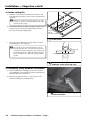
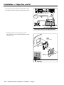
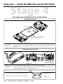
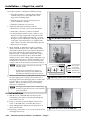
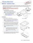
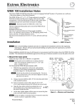
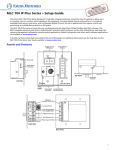
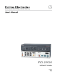
1
E: ABL m L I A e O AV ® yst ALS eVault S eo. . Vid Pol The tallation tron.com .ex Ins www t a t i View PoleVault® Systems (featuring the PVS 305SA) Installation Guide 68-1691-01 Rev. A 08 09 Precautions Safety Instructions • English Warning This symbol is intended to alert the user of important operating and maintenance (servicing) instructions in the literature provided with the equipment. Power sources • This equipment should be operated only from the power source indicated on the product. This equipment is intended to be used with a main power system with a grounded (neutral) conductor. The third (grounding) pin is a safety feature, do not attempt to bypass or disable it. This symbol is intended to alert the user of the presence of uninsulated dangerous voltage within the product’s enclosure that may present a risk of electric shock. Power disconnection • To remove power from the equipment safely, remove all power cords from the rear of the equipment, or the desktop power module (if detachable), or from the power source receptacle (wall plug). Caution Read Instructions • Read and understand all safety and operating instructions before using the equipment. Retain Instructions • The safety instructions should be kept for future reference. Follow Warnings • Follow all warnings and instructions marked on the equipment or in the user information. Avoid Attachments • Do not use tools or attachments that are not recommended by the equipment manufacturer because they may be hazardous. Consignes de Sécurité • Français Power cord protection • Power cords should be routed so that they are not likely to be stepped on or pinched by items placed upon or against them. Servicing • Refer all servicing to qualified service personnel. There are no user-serviceable parts inside. To prevent the risk of shock, do not attempt to service this equipment yourself because opening or removing covers may expose you to dangerous voltage or other hazards. Slots and openings • If the equipment has slots or holes in the enclosure, these are provided to prevent overheating of sensitive components inside. These openings must never be blocked by other objects. Lithium battery • There is a danger of explosion if battery is incorrectly replaced. Replace it only with the same or equivalent type recommended by the manufacturer. Dispose of used batteries according to the manufacturer’s instructions. Avertissement Ce symbole sert à avertir l’utilisateur que la documentation fournie avec le matériel contient des instructions importantes concernant l’exploitation et la maintenance (réparation). Alimentations• Ne faire fonctionner ce matériel qu’avec la source d’alimentation indiquée sur l’appareil. Ce matériel doit être utilisé avec une alimentation principale comportant un fil de terre (neutre). Le troisième contact (de mise à la terre) constitue un dispositif de sécurité : n’essayez pas de la contourner ni de la désactiver. Ce symbole sert à avertir l’utilisateur de la présence dans le boîtier de l’appareil de tensions dangereuses non isolées posant des risques d’électrocution. Déconnexion de l’alimentation• Pour mettre le matériel hors tension sans danger, déconnectez tous les cordons d’alimentation de l’arrière de l’appareil ou du module d’alimentation de bureau (s’il est amovible) ou encore de la prise secteur. Attention Lire les instructions• Prendre connaissance de toutes les consignes de sécurité et d’exploitation avant d’utiliser le matériel. Conserver les instructions• Ranger les consignes de sécurité afin de pouvoir les consulter à l’avenir. Respecter les avertissements • Observer tous les avertissements et consignes marqués sur le matériel ou présentés dans la documentation utilisateur. Eviter les pièces de fixation • Ne pas utiliser de pièces de fixation ni d’outils non recommandés par le fabricant du matériel car cela risquerait de poser certains dangers. Protection du cordon d’alimentation • Acheminer les cordons d’alimentation de manière à ce que personne ne risque de marcher dessus et à ce qu’ils ne soient pas écrasés ou pincés par des objets. Réparation-maintenance • Faire exécuter toutes les interventions de réparation-maintenance par un technicien qualifié. Aucun des éléments internes ne peut être réparé par l’utilisateur. Afin d’éviter tout danger d’électrocution, l’utilisateur ne doit pas essayer de procéder lui-même à ces opérations car l’ouverture ou le retrait des couvercles risquent de l’exposer à de hautes tensions et autres dangers. Fentes et orifices • Si le boîtier de l’appareil comporte des fentes ou des orifices, ceux-ci servent à empêcher les composants internes sensibles de surchauffer. Ces ouvertures ne doivent jamais être bloquées par des objets. Lithium Batterie • Il a danger d’explosion s’ll y a remplacment incorrect de la batterie. Remplacer uniquement avec une batterie du meme type ou d’un ype equivalent recommande par le constructeur. Mettre au reut les batteries usagees conformement aux instructions du fabricant. Sicherheitsanleitungen • Deutsch Vorsicht Dieses Symbol soll dem Benutzer in der im Lieferumfang enthaltenen Dokumentation besonders wichtige Hinweise zur Bedienung und Wartung (Instandhaltung) geben. Stromquellen • Dieses Gerät sollte nur über die auf dem Produkt angegebene Stromquelle betrieben werden. Dieses Gerät wurde für eine Verwendung mit einer Hauptstromleitung mit einem geerdeten (neutralen) Leiter konzipiert. Der dritte Kontakt ist für einen Erdanschluß, und stellt eine Sicherheitsfunktion dar. Diese sollte nicht umgangen oder außer Betrieb gesetzt werden. Dieses Symbol soll den Benutzer darauf aufmerksam machen, daß im Inneren des Gehäuses dieses Produktes gefährliche Spannungen, die nicht isoliert sind und die einen elektrischen Schock verursachen können, herrschen. Stromunterbrechung • Um das Gerät auf sichere Weise vom Netz zu trennen, sollten Sie alle Netzkabel aus der Rückseite des Gerätes, aus der externen Stomversorgung (falls dies möglich ist) oder aus der Wandsteckdose ziehen. Achtung Lesen der Anleitungen • Bevor Sie das Gerät zum ersten Mal verwenden, sollten Sie alle Sicherheits-und Bedienungsanleitungen genau durchlesen und verstehen. Aufbewahren der Anleitungen • Die Hinweise zur elektrischen Sicherheit des Produktes sollten Sie aufbewahren, damit Sie im Bedarfsfall darauf zurückgreifen können. Befolgen der Warnhinweise • Befolgen Sie alle Warnhinweise und Anleitungen auf dem Gerät oder in der Benutzerdokumentation. Keine Zusatzgeräte • Verwenden Sie keine Werkzeuge oder Zusatzgeräte, die nicht ausdrücklich vom Hersteller empfohlen wurden, da diese eine Gefahrenquelle darstellen können. Instrucciones de seguridad • Español Schutz des Netzkabels • Netzkabel sollten stets so verlegt werden, daß sie nicht im Weg liegen und niemand darauf treten kann oder Objekte darauf- oder unmittelbar dagegengestellt werden können. Wartung • Alle Wartungsmaßnahmen sollten nur von qualifiziertem Servicepersonal durchgeführt werden. Die internen Komponenten des Gerätes sind wartungsfrei. Zur Vermeidung eines elektrischen Schocks versuchen Sie in keinem Fall, dieses Gerät selbst öffnen, da beim Entfernen der Abdeckungen die Gefahr eines elektrischen Schlags und/oder andere Gefahren bestehen. Schlitze und Öffnungen • Wenn das Gerät Schlitze oder Löcher im Gehäuse aufweist, dienen diese zur Vermeidung einer Überhitzung der empfindlichen Teile im Inneren. Diese Öffnungen dürfen niemals von anderen Objekten blockiert werden. Litium-Batterie • Explosionsgefahr, falls die Batterie nicht richtig ersetzt wird. Ersetzen Sie verbrauchte Batterien nur durch den gleichen oder einen vergleichbaren Batterietyp, der auch vom Hersteller empfohlen wird. Entsorgen Sie verbrauchte Batterien bitte gemäß den Herstelleranweisungen. Advertencia Este símbolo se utiliza para advertir al usuario sobre instrucciones importantes de operación y mantenimiento (o cambio de partes) que se desean destacar en el contenido de la documentación suministrada con los equipos. Alimentación eléctrica • Este equipo debe conectarse únicamente a la fuente/tipo de alimentación eléctrica indicada en el mismo. La alimentación eléctrica de este equipo debe provenir de un sistema de distribución general con conductor neutro a tierra. La tercera pata (puesta a tierra) es una medida de seguridad, no puentearia ni eliminaria. Este símbolo se utiliza para advertir al usuario sobre la presencia de elementos con voltaje peligroso sin protección aislante, que puedan encontrarse dentro de la caja o alojamiento del producto, y que puedan representar riesgo de electrocución. Desconexión de alimentación eléctrica • Para desconectar con seguridad la acometida de alimentación eléctrica al equipo, desenchufar todos los cables de alimentación en el panel trasero del equipo, o desenchufar el módulo de alimentación (si fuera independiente), o desenchufar el cable del receptáculo de la pared. Precaucion Leer las instrucciones • Leer y analizar todas las instrucciones de operación y seguridad, antes de usar el equipo. Conservar las instrucciones • Conservar las instrucciones de seguridad para futura consulta. Obedecer las advertencias • Todas las advertencias e instrucciones marcadas en el equipo o en la documentación del usuario, deben ser obedecidas. Evitar el uso de accesorios • No usar herramientas o accesorios que no sean especificamente recomendados por el fabricante, ya que podrian implicar riesgos. 安全须知 • 中文 这个符号提示用户该设备用户手册中有重要的操作和维护说明。 这个符号警告用户该设备机壳内有暴露的危险电压,有触电危险。 注意 阅读说明书 • 用户使用该设备前必须阅读并理解所有安全和使用说明。 保存说明书 • 用户应保存安全说明书以备将来使用。 遵守警告 • 用户应遵守产品和用户指南上的所有安全和操作说明。 避免追加 • 不要使用该产品厂商没有推荐的工具或追加设备,以避免危险。 Protección del cables de alimentación • Los cables de alimentación eléctrica se deben instalar en lugares donde no sean pisados ni apretados por objetos que se puedan apoyar sobre ellos. Reparaciones/mantenimiento • Solicitar siempre los servicios técnicos de personal calificado. En el interior no hay partes a las que el usuario deba acceder. Para evitar riesgo de electrocución, no intentar personalmente la reparación/mantenimiento de este equipo, ya que al abrir o extraer las tapas puede quedar expuesto a voltajes peligrosos u otros riesgos. Ranuras y aberturas • Si el equipo posee ranuras o orificios en su caja/alojamiento, es para evitar el sobrecalientamiento de componentes internos sensibles. Estas aberturas nunca se deben obstruir con otros objetos. Batería de litio • Existe riesgo de explosión si esta batería se coloca en la posición incorrecta. Cambiar esta batería únicamente con el mismo tipo (o su equivalente) recomendado por el fabricante. Desachar las baterías usadas siguiendo las instrucciones del fabricante. 警告 电源 • 该设备只能使用产品上标明的电源。 设备必须使用有地线的供电系统供电。 第三条线 (地线)是安全设施,不能不用或跳过 。 拔掉电源 • 为安全地从设备拔掉电源,请拔掉所有设备后或桌面电源的电源线,或任何接到市 电系统的电源线。 电源线保护 • 妥善布线, 避免被踩踏,或重物挤压。 维护 • 所有维修必须由认证的维修人员进行。 设备内部没有用户可以更换的零件。为避免出现 触电危险不要自己试图打开设备盖子维修该设备。 通风孔 • 有些设备机壳上有通风槽或孔,它们是用来防止机内敏感元件过热。 不要用任何东 西挡住通风孔。 锂电池 • 不正确的更换电池会有爆炸的危险。必须使用与厂家推荐的相同或相近型号的电池。 按照生产厂的建议处理废弃电池。 Introduction FCC Class B Notice This equipment has been tested and found to comply with the limits for a Class B digital device, pursuant to part 15 of the FCC Rules. These limits are designed to provide reasonable protection against harmful interference in a residential installation. This equipment generates, uses and can radiate radio frequency energy and, if not installed and used in accordance with the instructions, may cause harmful interference to radio communications. However, there is no guarantee that the interference will not occur in a particular installation. If this equipment does cause harmful interference to radio or television reception, which can be determined by turning the equipment off and on, the user is encouraged to try to correct the interference by one or more of the following measures: • Reorient or relocate the receiving antenna. • Increase the separation between the equipment and receiver. • Connect the equipment into an outlet on a circuit different from that to which the receiver is connected. • Consult the dealer or an experienced radio/TV technician for help. N This unit was tested with shielded cables on the peripheral devices. Shielded cables must be used with the unit to ensure compliance. Overview This guide covers the installation of the Extron PoleVault® System in a drop ceiling room with a wood or concrete structural ceiling. If the location has a concrete or beam style ceiling, alternative ceiling mounts can be obtained separately from Extron (see 2c, "Optional items", later in this chapter). It is assumed that the installer has some knowledge and experience of A/V, electrical, or electronic device installation. This guide takes the A/V installer through the steps for installation and connection of each of the system’s component parts. It may be that the locations for the devices (e.g., wall plates, projector, and screen) have been pre-determined. However, some room installation examples are given to help in installations where final location is yet to be determined. The PoleVault System Extron PoleVault Systems are easy-to-use, network-enabled, all-inclusive packages, making them ideal for single-projector K-12 classrooms. PoleVault Systems use economical twisted pair cables for transmitting signals and include network connectivity for Web-based asset management, monitoring, and control. N The hardware and devices listed on the inventory pages have detailed safety information, installation, set-up, and configuration instructions, and should be referred to as needed. For operation and setup of the projector, screen, and input devices, refer to the relevant manufacturer's manuals supplied with those devices. A PoleVault System Installation video is viewable online at www.extron.com. This video is also a step by step guide to installing PoleVault System and is useful for first-time installations. PoleVault Systems Installation • Introduction 1-1 Introduction, cont'd Extron FF 120 Flat Field Ceiling Speakers - 1 Pair Extron SPK 18 - 35' Extron Priority Page Sensor (Optional Accessory) Cable From PA system UTP Cable (CAT 5/5E/6) To PoleVault Switcher Ceiling Mounted Paging Speaker Extron PCM 340 Extron VoiceLift Receiver Projector Drop Ceiling Mount (Optional Accessory) Extron PVS 305SA Slotted Projector Mount Pole PoleVault® Switcher Extron PMK 550 Easy Installation Pole Mount Kit CON FIG 1 INPU 2 T SELE CTIO 3 N 4 5 AUX INPU T AUD IO AUD PEAK NORMA L SIGNAL IO LEVE POLE PVS L ADJUVAUL MIC ST 305 T SWIT NORMA IFT L SIGNAL SA CHER PEAK VOICEL PAGIN SENS G OR SENS ITIVIT Y Extron UPB 25 Universal Projector Mounting Bracket Assistive Listening System Extron PVT CV D Composite Video & Audio Input Wallplate VID EO L IN AUD IO IN R IR OUT S G AUD IN IO AUD OUTIO COM PUT ER IN MO NIT OR IR OUT OUT S G RS-232 to Switcher Extron PVT RGB D Plus DVD/VCR Combo SP LA Y OF F LU ME VC R 1 DV VGA & Audio Input Wallplate PC RS-232 to Projector CO NFI G 3 4 ML C 10 4 IP PL US Extron MLC 104 IP Plus AU DIO IN CO MP UT ER IN VID EO L IN AUD IO IN R IR OUT S PC D 2 Extron PVT RGB D G Extron PVT CV D MediaLink ® Controller Composite Video & Audio Input Wallplate TCP/IP Network R PW VGA & Audio Input Wallplate DI ON VO Ext P R W OFF/MUTE/CHG ON ron CHARGE IR Emitter Ext Camera OFF/MUTE/CHG ON ron CHARGE n ro xt E Document Camera Extron VoiceLift ™ Microphone and Charging Station (Optional Accessory) PoleVault System installation and wiring overview 1-2 PoleVault Systems Installation • Introduction Before you Begin Installation - Planning Before installation is started, several major factors must be considered to ensure that the installation process is as smooth and trouble free as possible, and that the final finished project meets the needs of the customers, users, audiences, and installer. The installation consideration on the following pages, though not comprehensive, should be consulted to help ensure that key aspects have been considered. 1. Room layout a. The room The application diagram below shows a typical classroom installation. PoleVault System DISPLAY ON OFF VOLUME VCR 1 DVD 2 PC 3 CONFIG Extron 4 MLC 104 IP Plus DISPLAY ON OFF VOLUME VCR 1 DVD 2 PC 3 CONFIG 4 Extron MLC 104 IP Plus Typical classroom installation Room factors to be considered should include, but are not confined to: • Room size, orientation, and layout: Audience factors (e.g. number, ADA requirements, seating arrangements) Existing installed furniture (bookcases, racks, cabinets, workbenches, sinks, etc.) Windows, doors, and support pillar locations in relationship to the proposed screen location • Ceiling and wall type (important in assessing the installation hardware needed) Ceiling type: dropped, spline, hard lid etc., structural type (wood, concrete, trusses), plenum or non-plenum Wall type: drywall, cement, brick, etc. W Check the structural ceiling to ensure that it can handle a load four times the weight of the final setup. PoleVault Systems Installation • Introduction — Planning 1-3 Introduction — Planning, cont’d • Lighting Type and control (important for projector image viewing) Ambient light from windows Student Desks Speaker Location Windows Projector/Switcher Location MLC Controller Location Teacher’s Desk TV / VCR / DVD Inputs PVT A/V Wallplate Location Screen/White Board Location Example classroom installation b. Location of the screen and projector • Proposed screen location Normally located at the front center of the room (not covering fire alarm strobes when screen is lowered) Dimensions and type of screen (maximum image size, motorized or hanging screen) • Proposed projector location Aligned with center of the screen and not an obstruction to viewing Projector's throw distance (maximum and minimum limits to the screen) of the image Horizontal offset (horizontal distance from the center of the lens to the center of the projector) Vertical offset of the projected image (height relationship between the projector and the screen) Projector angle (image projected up, down, or horizontal to screen) Power source for the projector: existing and accessible or needing installation Projector weight. The Universal Projector Bracket (UPB 25) supports a maximum weight of 25 lbs. Overhead clearances (refer to a copy of "ADA Standards for Accessible Design", "Section 4-4", "Head Room" for ADA requirements) 4" (10 cm) Max 80" (203 cm) Min Greater than 27" (68.5 cm) Walking Parallel to a Wall (ADA referenced figure 8a, redrawn) ADA overhead and side clearance requirements • Viewing obstructions Pillars, furniture etc., window locations for glare reduction, obstructions between projector and screen 1-4 PoleVault Systems Installation • Introduction — Planning c. Location of MediaLink® Controller and Wall Plates • Forward and side reach (for full details refer to a copy of "ADA Standards for Accessible Design", "Section 4-2", "Space Allowance and Reach Ranges") 30" (76 cm) 10" (25.5 cm) Max 48" (122 cm) Max 54" (137 cm) Max High / Low Side Reach Limits (ADA referenced figure 6b, redrawn) High Forward Reach Limits (ADA referenced figure 5a, redrawn) 30" (76 cm) 46" (117 cm) 34" Max (86.5 cm) 9" (23 cm) Min 15" (38 cm) Min 24" (61 cm) Max Side Reach over Obstruction Limits (ADA referenced figure 6c, redrawn) ADA high/low forward, side and over obstruction reach limit requirements • Location of source devices Desk, table, or rack mounted, and proximity to proposed transmitter location (wall, podium, or furniture) • Cabling obstacles Studs, utility pipes, power supply location (raceway installation needed?) • Network drop for MediaLink Controller Wall or floor cabled d. Type and location of the speakers • Speaker type based on room ceiling and wall type • Total number and spacing of speakers Based on ceiling height and room size • Audience seating and room acoustics Desired spread and evenness of sound coverage and ambient noise level compensation Student Desks Each speaker covers one-fourth of listening area. Speaker Location Windows Projector/Switcher Location MLC Controller Location Teacher’s Desk TV / VCR / DVD Inputs PVT A/V Wallplate Location Screen/White board Location Example classroom with four speaker installation PoleVault Systems Installation • Introduction — Planning 1-5 Introduction — Inventory Overview 2. Inventory a. Included items The PoleVault System (PVS xxx) ships in two boxes. The larger box (42-1xx-xx) contain the devices and hardware, individually boxed and labeled. The smaller box (42-120-03) contains only the FF 120 speakers. Each PVS system has the same quantities of speakers, hardware and devices, but differs in the number and type of PoleVault A/V Source Input Wall Plates, and are shipped as follows: • PVS 200 (part # 42-108-03) includes one PVT RGB D and one PVT CV D • PVS 300 (part # 42-109-03) includes two PVT RGB D and one PVT CV D • PVS 400 (part # 42-110-03) includes two PVT RGB D and two PVT CV D Carefully check all the received items against the following lists. PoleVault® System Devices and Hardware PoleVault System 42-108-03 (or 42-109-03*, or 42-110-03*) PCM 340 PCM 340 White 70-656-23 UPB 25 PMK 550 UPB 25 White 60-773-03 PMK 550 White 70-655-03 CABLES (1) SPK 18, 35' (1) MVGA M-M, 3' PCM 340 Projector Drop Ceiling Mount UPB 25 Universal Projector Bracket PMK 550 Pole Mount Kit (1) V RCA, 3' (1) MLC, PW/RS232/VC, 50' (4)Turnbuckles (5) Lag eye bolts (5) Concrete anchors (2) Cable clamps, Gal Steel (1) Safety wire (15 ft. 1/8 in. dia) (2) Tie wire (30 ft., 14 AWG) (4) T-frame screws (2) Set screws (1) Location screw (11) Hole plugs (4) Adhesive pads (1) 25 in. Slotted pipe (1) Escutcheon ring (1) Snap-in trim piece 1-6 (4) M6 x 40 mm screws (4) M5 x 40 mm screws (4) M4 x 40 mm screws (4) M3 x 40 mm screws (4) 0.328 ID washers (4) #10 washers (4) #6 washers (4) Adhesive pads (1) Hex key (4) 10-32 Cover screws (3) 4-40 screws (2) Velcro™ pads (1) Velcro strap NB: Items not drawn to scale PoleVault Systems Installation • Introduction — Inventory Overview (1) IR SERIAL COMM, 50' CAT5 T568A Patch, 50' Quantity varies depending on PVS system ordered. These may be boxed separately or loose inside larger box. PoleVault System Devices and Hardware, cont’d PoleVault System 42-108-03 (or 42-109-03*, or 42-110-03*) PVS 305SA PVT CV D PVT RGB D Plus PVT CV D White 60-819-33 PVT RGB D White 60-820-13 PVS 305SA 60-986-01 VIDEO IN AUDIO IN AUDIO IN L POLEVAULT SWITCHER 3 COMPUTER IN FF 120 FF 120 42-120-03 PVS 305SA INPUT SELECTION 2 MLC 104 IP Plus White 60-818-03 R S G 1 MLC 104 IP Plus 4 AUDIO LEVEL ADJUST 5 INPUT PEAK MIC NORMAL CONFIG SIGNAL AUX AUDIO PEAK IR OUT DISPLAY PAGING SENSOR ON NORMAL VOICELIFT SIGNAL VCR OFF DVD VOLUME PVS 305SA PoleVault Switcher 1 SENSITIVITY PC PVT CV D Wallplate PVT RGB Plus D Wallplate or optional PVT RGB D Plus White 60-820-33 IN 2 3 CONFIG 4 MLC 104 IP Plus MLC 104 IP Plus MediaLink Controller FF 120 Speakers AUDIO OUT COMPUTER IN MONITOR OUT S G IR OUT (1) 3-pole connector (3) 5-pole connector (1) Audio connector, 4-pole (2) Securing screws (5) Tie wraps (1) Mud ring (2) PVT mounting screws (1) Decora® Faceplate (2) Faceplate screws (1) 2-pole connector PVT RGB Plus D Wallplate (1) Mud ring (2) PVT mounting screws (1) Decora® Faceplate (2) Faceplate screws (1) Power supply (1) Power cord (2) Cable clamps - Anchor ring (2) T-rails (1) Mud ring (8) Mud ring screws (8) Replacement screws (2) Faceplates (1) White (on unit) (1) Black *Part #s 42-109-03 and 42-110-03 contain 3 or 4 PoleVault Wallplates, according to the type ordered. N If any items in the PoleVault System boxes are damaged or missing, contact the Extron Technical Hotline (see rear cover for contact numbers). PoleVault Systems Installation • Introduction — Inventory Overview 1-7 Introduction — Inventory Overview, cont’d b. Items not included The following items are not included. However, input and display devices are essential parts of the system, and at any installation they may vary depending on their use. This list suggests various devices that may be used. • Projector (or display device) • Screen (and mounting hardware) • Input devices, such as: DVD/CD/VCR combo player (and cables) Document camera (and cables) PC or Mac (with keyboard, mouse, local monitor, VGA cables, RJ-45 network cables, power cords, and, where desired, a P/2 DA2 or DA for PC signal to local monitor) • Installation hardware needed (may vary per installation): Bolts for concrete structural ceilings where needed Toggles (used for screen mounting on dry wall) S-hooks for hanging the screen Spare ceiling tiles in case of accidental damage during installation Electrical box, where installation of a box on the PCM 340 is desired Safety wire, lag eye bolts, and strain reliefs for installation and securing ceiling speakers Heat shrink, extension cord c. Optional items The optional Extron products suggested below can be added to or substituted for items in the standard PoleVault System. • Optional accessories: Wall mount speakers (e.g., SI 26) or extra ceiling speakers MLC 104 IP Plus DV+ controller (includes DVD/VCR IR control) MLC 104 IP Plus L controller (with lectern faceplate) MLC 104 IP Plus AAP controller (with AAP opening) MLC 226 IP controller Priority Page Sensor Kit P/2 DA2 • Optional installation hardware: FCMP (flat ceiling mount) ACMP (angled ceiling mount) SMB (surface mount boxes for installing the MLC on a podium or desk) EWB (external wall boxes to mount devices for a surface raceway system) MLM-WB+ (lockable metal wall box with flip-down 4U rack space) • Optional A/V source inputs: PVT RGB D Plus (RGB Decora mount model, with IR and local monitor output) PVT CV AAP (composite video architectural adapter plate model) PVT RGB AAP (RGB architectural adapter plate model) PVT RGB (RGB rack mount model) PVT SW RGB (RGB rack mount model with switching capabilities) PVT CV (composite video rack mount model) PVT RGB CV (RGB and composite video rack mount model) • Optional speakers: SI 3 (Compact Full-Range Surface Mount Speakers) SI 26X (Two-Way Open Back Ceiling Speakers) SI 26W (Two-Way-In-Wall Speakers with 6.5" Woofer) SI 28W (Two-Way-In-Wall Speakers with 8" Woofer) SI 26CT (Two-Way Ceiling Speakers with 8" Back Can and Transformer) SI 26 (Two-Way Surface Mount Speakers with 6.5" Woofer) SI 3C LP ( Full-Range Ceiling Speakers with 4" Low Profile Back Can) 1-8 PoleVault Systems Installation • Introduction — Inventory Overview d. Installation tools To aid the professional installer, this checklist gives the tools recommended to complete the installation. Tools should include, but are not confined to: • Laser level, or two levels (large for screen installation, small for wall plates and projector mounts) • Tape measure • Stud finder • Drill and drill bit set including a Unibit to cut through metal studs • Extension drill bit (3/4" min., 4 to 8 foot length, to drill through fire-breaks) • Socket set • Pipe strap or wrapped pipe wrench • Lineman’s pliers and wire strippers • Standard screwdriver set and Tweeker • Cable cutters (to cut safety wire) • Dry wall saw and hacksaw blade mounted on handle (for cutting ceiling tiles) • Flashlight and safety goggles • Razor knife • 2" hole saw • Painter's tape (to mark up walls), pencil, and marker pen • RJ-45 crimpers and RJ-45 connectors • Voltage tester • Fish tape, pull string, and electrical tape (for taping fish tape to pull string) • Zip ties • Vacuum cleaner • Heat gun PoleVault Systems Installation • Introduction — Inventory Overview 1-9 Installation Overview This overview outlines the basic steps for installing the PoleVault System. Detailed description of these steps is given in five sections, Stages One though Five. N Additional installation hardware is needed and should be supplied by the installer. See Introduction, “Items not included” on page 1-8, for a list. Optional accessories may be desired for this installation. For a list see Introduction, “Optional items”, on page 1-8, or visit www.extron.com for details. Refer to local building standards and codes to verify that the installation will meet all the regulatory requirements. Observe all local and national building and safety codes, UL requirements, and ADA Accessibility Guidelines. Refer to the specifications at the end of this guide for system hardware weights and dimensions. Carefully check inventory of PoleVault system packages, input and output devices, any optional accessories, and installation hardware before commencing. Outline of installation steps Stage One — Install the Screen and Projector. c Mark the screen location (page 2-3). c Install projector to verify location (page 2-3). c Verify the image location (page 2-4). c Cut the ceiling tile (page 2-5). c Preliminary safety hardware installation (page 2-5). c Finish projector drop ceiling mount installation (page 2-6). c Secure the projector drop ceiling mount to the ceiling (page 2-6). c Install the electrical box (if required) (page 2-7). c Install the screen (page 2-7). Stage Two — Install the A/V Source Input Wall Plates and MLC 104 IP Plus. c Install the mud rings (page 2-10). c Pull cables (at the input locations) (page 2-11). c Install the wall plates (page 2-12). c Install the MediaLink Controller (page 2-13). Stage Three — Install the FF 120 Speakers. c Cut the ceiling tile (page 2-17). c Install the speaker on the drop ceiling (page 2-17 ). c Terminate the speaker cable for the PVS switcher (page 2-18). Stage Four — Install the PMK 550 and the PVS 305SA. c Install the PMK 550 base plate (page 2-20). c Pull the cables (at the switcher location) (page 2-21). c Finish installing the pole mount kit (page 2-22). Stage Five — Configure the switcher and the system. c Configure the switcher — MLS Switcher Configuration program (page 2-24). c Configure the system — Global Configurator (page 2-25). c Test the system (page 2-26). c Final installation (page 2-27). Where possible in the following pages, line drawings and photos from an actual installation are used to clarify some of the steps discussed in the text. Each image has a number (e.g., Ñ) corresponding to the particular step described. 2-1 PoleVault Systems Installation • Installation Stage One — Install the Screen and Projector Stage 1 This stage involves installing the three pieces of hardware shown below. Slotted Pipe (supplied with PCM 340) PCM 340 Projector Drop Ceiling Mount 1-gang and 2-gang Accessory Mounting Points (e.g., Power Sockets) Base Plate Pipe Adapter Pipe Adapter Plate Wing Nuts (4) T-frame Securing Screws (4) Pipe Adapter Set Screws (2) Where it goes: Attaches to structural ceiling, rests on suspended ceiling. What it does: Holds slotted pipe, PoleVault pole mount kit (PMK 550 - see Stage 4), and projector. Slotted Pipe Where it goes: Locks into place in PCM 340 pipe adapter. What it does: Holds pole mount kit and projector. UPB 25 Universal Projector Bracket (shown separated into the two sections) Projector Bracket (Bottom Section) Adjuster Plate (Top Section) Set Screws (2) Vertical Angle Adjustment Screws (4) Horizontal Angle Adjustment Screws (4) Adjuster Plate Locking Screws (4) Projector Securing Screw Threaded Barrels (4) Pivot Point Screws (4) Arm Adjustment Screws (4) Pivot Point Screw Security Flange (on rear) Security Flange (on rear) 360° Movement Where it goes: Adjuster Plate screws onto base of slotted pipe, and Projector Bracket attaches to projector. What it does: Attaches projector to PCM 340. Allows projector orientation to be adjusted in three planes. PoleVault Systems Installation • Installation — Stage 1 2-2 Installation — Stage One, cont’d 1. Mark screen location a. Mark the center line and the outer edges of the screen. T When marking the location of screens, devices, or the site for installing transmitters and MediaLink control devices, use painters tape to avoid wall surface damage. When marking the center line of the screen, where possible, keep it aligned with the center of the ceiling tile. This makes the projector installation and alignment easier. 1a Mark the screen location b. Mark any structural studs, utility pipes, conduits, or fire-breaks before drilling the hardware holes. Do not drill the holes at this time. 2. Install projector to verify location Minimum/Maximum Throw Distance Marks a. Remove the ceiling tiles, and mark the maximum and minimum throw distances on the T-frame. Refer to the projector manufacturer’s installation manual for more information. b. Place the PCM 340 over the T-frame, between the two marks. Lightly tighten the T-frame securing screws. The T-frame screws can be used on the outside or the inside to secure the PCM to the T-frame. N Place the PCM 340 on the T-frame so that the pipe adapter slides left to right in relation to the proposed screen location, rather than towards and away from it. This makes aligning/centering the image easier. c. Slide the slotted pipe up into the pipe adapter. Adjust to the desired height and align the location holes and pipe holes. Insert the location screw, lightly tightening it down using a 5/32 inch hex wrench. Insert and lightly tighten down the set screws onto the pipe. Do not overtighten as the pipe is removed and replaced later during installation. d. Take the UPB 25 and back out the set screws using a 3/32 inch hex wrench on the top portion of the adjuster plate (see a below), and then screw the plate onto the base of the pipe. Align it so the security flange is at the rear. a Adjuster Plate PCM 340 2b Place the PCM 340 on the T-bar Align Pipe holes with location screw holes. Insert location screw and secure. 2c Insert and secure the slotted pipe Set Screws (2) Loosen the four Adjuster Plate Locking Screws and slide the Adjuster Plate away from the Projector Bracket b Projector Bracket Security flange Adjuster Plate Locking Screws (4) 2-3 PoleVault Systems Installation • Installation — Stage 1 2d Screw the adjuster plate onto the base of the pipe. e. Using suitable screws, mount the projector onto the projector bracket, i.e., the lower portion of the UPB 25 as shown in step 2e’s image. Align it so the security flange is at the rear. A minimum of three arms need to be attached to the projector. Adjust the arms to fit as needed. Lock down the arm adjustment screws. T Adjust the threaded barrels at the end of each arm to level the bracket. Security Flange 2e Attach the bracket to the projector f. Lift the projector up to the adjuster plate and slide it into place. Tighten down the locking and pivot screws. 2f Slide and lock the projector onto the adjuster plate 3. Verify the image location a. Connect a power cable to the projector and turn it on. b. Verify image size and location by loosening the PCM 340 pipe adapter plate wing nuts, and adjust the plate (left-right) to center the image. Projector Center Line T Remember to include the vertical and horizontal offsets when aligning the projector. Refer to the projector manual for information. Measure the horizontal offset c. When satisfied tighten down the plate wing nuts. Lens Center Line T Horizontal offset PoleVault Systems Installation • Installation — Stage 1 2-4 Installation — Stage One, cont’d 4. Cut the ceiling tile a. Mark the location of the PCM 340 on the T-frame. This aids putting it back in the correct location when the tile is replaced. X" T Mark the screen direction on back of the tile (e.g. with an arrow or “to front”) to help orientation of tile when replacing it after cutting. b. Measure the distances X and Y (see figure) from the inner vertical section of the front and left T-frame runners to the center of the Pipe Adapter Plate. Y" T-bar Minimum and Maximum Throw Distance Marks 4b Take measurements with the PCM 340 on the T-frame c. Using the X and Y dimensions, mark and cut a hole for the slotted pipe in the ceiling tile. T Place the tile on a box and mark the hole’s center on the underside of the tile. Use a hole saw bit to start to cut the hole by hand (turning bit counter clockwise) to avoid damaging the tile. When the drill bit is through the tile, turn the tile over and finish cutting from the top side. Top Side of Tile Underside of Tile 4c Mark and start cutting the hole on the underside. Finish on the top side. 5. Preliminary safety hardware installation a. Mark and drill holes at 10 degrees out from vertical for each turnbuckle. Drill a fifth hole directly centered above the PCM 340 for the safety cable. b. Install an appropriate anchors or lag eye bolt for the structural ceiling into each drilled hole. 5a Mark structural ceiling for lag eye 2-5 PoleVault Systems Installation • Installation — Stage 1 bolt installation 6. Finish Projector Drop Ceiling Mount installation a. Detach the projector bracket/projector from the adjuster plate. Do not remove the projector bracket from the projector. b. Unscrew the UPB 25 adapter plate from the mounting pole. c. Loosen the set screws on the PCM 340 and the pipe location screw and remove the mounting pole, then loosen the T-frame securing screws and remove the PCM 340 from its marked location. d. Replace the cut ceiling tile, checking its orientation to align the hole with the PCM 340. e. Replace the PCM 340 over the ceiling tile, slide the slotted pipe up through the tile and into the adapter plate. Realign the location holes with the pipe holes, insert and tighten down the location screw. Tighten the set screws. f. Tighten the four T-frame securing screws on the PCM 340. The T-frame securing screws can be used on either side of the frame. 6e Slide the pipe through the ceiling tile and into the pipe adapter plate 7. Secure the Projector Drop Ceiling Mount to the ceiling a. Attach the four turnbuckles to the mounting plate, one at each corner. C DO NOT rest or lean on the mounting plate or suspended ceiling when attaching turnbuckles, tie wire, or when drilling into the ceiling N For safest installation, insert the turnbuckle from the outside so that it hooks inwards. b. Cut four equal lengths of the supplied hanging wire, and loop the wire through the anchors or lag eye bolts, and the turnbuckles, then twist the wire around itself at least five times tightly at each end. c. Hand tighten the turnbuckles and level the plate so it just rests on the T-frame. C The four hanging wires should be taut, taking the full weight of the completed installation. Do not overtighten the turnbuckles or the T‑frame assembly could be lifted, making the suspended ceiling bowed and unsafe. d. Pass the braided safety cable through the fifth and center anchor and attach it to the center holes on either side of the plate. Ensure the cable is of equal length on both sides of the anchor and secure the cable using the cable clamps. 7a Attach turnbuckles at the corners Secure PCM to frame (from either side) PCM T-frame Adjust the turnbuckles to take up any slack in the hanging wire. 7c Hand tighten the turnbuckles PoleVault Systems Installation • Installation — Stage 1 2-6 Installation — Stage One, cont’d 8. Install the electrical box (if required) W All electrical installation should be performed by qualified personnel in accordance with local and national building codes, fire and safety codes, and local and national electrical codes. If required, the following method is recommended for integrating a 4S Raco electrical box (not supplied) on the PCM base plate (e.g., a Raco 231, 2 1/8 inch deep, 4x4 inch electrical box and a Raco 778, 1/2 inch raised, 4x4 inch plaster ring or similar). Install the Raco box on the PCM plate as follows: a. Attach the box to the plate, using the smallest notches in opposite corners of the cut-out (see figure 8a). Do not tighten the screws fully at this time. b. On the opposite side of the PCM plate, slide the plaster ring under the screws. The plaster ring anchors the box in place with PCM plate sandwiched between. c. Fully tighten the screws. W For safety, complete all wiring of the electrical boxes and accessories after the plate is fully installed and secure. d. Mark and cut a hole in the ceiling tile for the electrical box opening. 9. Install the Screen a. Following the screen manufacturer’s guidelines, continue to install the screen mounting brackets and then hang the screen. T Use S-hooks to hang the screen from the brackets. Bend the ends of the S-hooks so the screen does not fall when it is rolled up. 2-7 PoleVault Systems Installation • Installation — Stage 1 Raco 231 Use the smallest notches when attaching the Raco box. Raco 778 8a Install Raco box and plaster ring Stage Two — Install the Wall Plates and MLC 104 IP Plus Stage 2 This stage involves installing the devices shown below. PVT CV D and PVT RGB D Plus PoleVault A/V Source Input Wall Plates* PVT CV D AUDIO IN L R Audio and Video input Connectors VIDEO IN AUDIO IN L R IR OUT S G IR Output COMPUTER IN Local Monitor Output Port S G IR OUT RGB A RGB B OUT OUT IR Output Decora Faceplate Audio and Video Output Port (at rear) Mounting Screws (2) Line Out Audio Input Connector (at rear) GS S G AUDIO OUT MONITOR OUT IR Input Connector (at rear) IR OUT IN Line Out Audio Output Port GRL Audio and Video input Connectors VIDEO IN PVT RGB D Plus IR Input Connector (at rear) Audio and Video Output Ports (2** at rear) ** Each RGB Wall Plate needs 2 Output Cables, A and B. Where it goes: Installs in a wall near input source location. What it does: Transmits an input source’s composite or RGB video signal, and audio signals to the switcher. * Wall plates included may differ slightly from those shown in this manual. MLC 104 IP Plus MediaLink Controller Captive screw connectors for: Mounting screws (4) Display/RS-232/IR Comm. Link Digital I/O, MLS/RS-232 Power DISPLAY VCR OFF 1 DISPLAY RS-232/IR ON Tx RUN 100 Rx GROUND IR OUT A B C D E COMM LINK +12V OUT GROUND DVD VOLUME 2 CM IR IN SCP Rx B 4 A CONFIG 2 MLS RS-232 3 DIGITAL I/O PC Tx GROUND POWER 12V MLC 104 IP PLUS 3 GROUND LAN PRESS TAB WITH TWEEKER TO REMOVE 1 Ethernet port GROUND +12V IN Right Side Rear View Location of MAC address 00-05-A6-01-6B-F5 Where it goes: Installs in a wall at a location convenient to user. What it does: Provides remote control of switcher and projector. PoleVault Systems Installation • Installation — Stage 2 2-8 Installation — Stage Two, cont’d Cables PVT transmitter installation • CAT 5 T568A signal transmission cables (connects PVT input wallplates to PVS 305SA switcher) CAT 5 Patch, 50 ft 26-637-50 MLC 104 IP Plus installation • MLC power and RS-232 control cable (connects the MLC controller to the MLC/Power control port on the PVS 305SA switcher) MLC, PW/RS-232/VC, 50 ft 26-626-50 • IR/RS-232 communications cable control cable (connects the MLC controller to the projector via RS-232 or to an IR emitter) IR SERIAL COMM, 50 ft 26-621-50 • LAN network cables (not supplied - connects the MLC controller to LAN) 2-9 PoleVault Systems Installation • Installation — Stage 2 N The installation must conform to national and local building and electrical codes, and UL requirements. Refer to the devices’ user manuals for details. 1. Install the mud rings Wall N These devices can be installed using the supplied mud ring or a wall box. If installing a box, allow enough depth for the plate, and the cables. The box should be at least 2.5 inches (6.4 cm) deep to accommodate the connectors and cables. If a suitable wall box is already installed, follow step 2 onwards. Wall Mounting Mud Ring a. Using the mud ring as a template, trace the inside of the mud ring onto the mounting surface. b. Cut out the material within the marked area. c. Insert the mud ring into the opening. The mud ring’s rear doglegs should fit easily into the opening. Flip over the mud ring doglegs and secure with the screws provided. T Use a level when fitting the mud ring. Repeat steps a to c for each additional input wall plate that needs to be installed. 1c Insert the mud ring. d. At the desired location mark the opening for the larger MLC 104 IP Plus mud ring. NOTE e. Repeat steps b and c. Rotate the dogleg out of the way to insert the mud ring into the wall. Wall Dogleg Dogleg Screw Equipment Mounting Holes Surface Mounting Hole Extron Mud Ring 1d Features for mud ring installation PoleVault Systems Installation • Installation — Stage 2 2-10 Installation — Stage Two, cont’d 2. Pull the cables (at the input locations) The following cables need to be installed: • CAT 5 cables for signal transmission from the A/V wall plates to the PVS 305SA N For PVT RGB D and PVT RGB D Plus wall plates, two CAT 5 signal cables for each input are needed. Maximum distance from the PVS 305SA to the Wall plates is 100 feet. The optimum distance is between 50 and 75 feet. Minimum distance is 15 feet. NOTE The CAT 5 cables supplied are terminated to the TIA 568A standard. Other CAT 5 cables can be used if they are TIA 568A or 568B standards and terminated to the same standard at both ends. • CAT 5 cables (not included) for MLC network connection • PoleVault switcher communication cable from the MediaLink controller (MLC PW/RS-232/VC, 50’, part # 26-626-50) • Projector communication cables from the MediaLink controller (IR Serial Comm, 50’, part # 26-621-50) Fasten the colored section to the cable first, then wrap the clear section around it. RGB #1A 2b Use the supplied labels for clear cable identification during installation. Signal Cable Label color RGB 1A (Input 1 RGB) Orange RGB 1 B (Input 1 RGB) Orange RGB 2A (Input 2 RGB) Yellow RGB 2B (Input 2 RGB) Yellow a. Drill cable pathways through any obstructions (e.g., wall caps, fire-breaks, or horizontal studs). RGB 3A (Input 3 RGB) Magenta RGB 3B (Input 3 RGB) Magenta b. Label the CAT 5 signal cables at both ends with the supplied labels. RGB 4A (Input 4 RGB) Light Green RGB 4B (Input 4 RGB) Light Green Video 3 (Input 3 Composite Vid) Dark Green Video 4 (Input 1 Composite Vid) Red c. Pull the cabling through the wall from the ceiling space down to the location of the transmitters and other wall devices, and out through the openings. T Secure cables with cable clamps to provide strain relief. Trim back the outer foil shield to the point where the cable exits the cable clamp, and insulate exposed cable shields with heat shrink to reduce the chance of short circuits. Both braided and foil shields should be connected to an equipment ground at the other end of the cable. 2-11 PoleVault Systems Installation • Installation — Stage 2 2c Pull the cables at each location. 3. Install wall plates a. Connect the CAT 5 cables to the rear of the input devices (for RGB devices, connect cable labeled A to port A and cable B to port B). b. If desired, for PVT RGB D Plus plates, use a three conductor audio cable and connect the audio return to the connector marked G (ground wire), R (black wire), and L (red wire). The other end will be connected to the “Line Out” connection on the PVS 305SA switcher. c. If desired wire the IR connection using a two conductor cable. Wire the ground to G and signal lead to S. The other end will be connected to the “IR Out” port of the MLC 104 IP Plus controller. 3a Connect the cables to the A/V source input devices at each location. Wall Wall Mounting Bracket (mud ring) Decora® Faceplate d. Mount each device into the mud ring, using the supplied screws. DIO UT O AU IN R IN UTE MP CO R ITO ON OU T M S G T IR e. Attach the supplied Decora faceplate. OU Extron PVT RGB D Plus f. Label the Decora plate with the supplied label, using the appropriate input number. This makes inputs easier to identify when configuring the switcher. g. Repeat steps a-f for other wall plates. 3b Mount the PVT in the mud ring, then 3c attach the Decora faceplate. PoleVault Systems Installation • Installation — Stage 2 2-12 Installation — Stage Two, cont’d 4. Install MediaLink Controller T Before cabling and installing the MLC 104 IP Plus, locate and write down the MAC address of the device for configuring the IP address. The 12 character alphanumeric address (e.g., 00-05-A6-03-9G-H4) can be found on a label on the side of the controller. T The length of exposed wire is critical to avoid transmission problems. Ensure the lengths given here are adhered to when stripping the cables for connection. Wire Bared 3/16" (5 mm) Max. Heat Shrink on Outer Jacket to Inner Conductor Transition Heat Shrink on Drain Wire 7/8" (22 mm) N If a drain wire is used, both ends of the wire must be covered by heat shrink to avoid accidental grounding. T Wire stripping lengths a. Connect the MLC power and RS-232 control cable (part # 26-626-50) as shown. N The MLC 104 IP Plus is powered from the PVS 305SA. DO NOT connect an external power supply to the MLC 104 IP Plus unless installing an optional secondary control panel. RS-232/MLC/IR Tx Rx IR +12V ABCDE PVS 204SA Switcher's rear panel RS-232/MLC/IR port From MLC 104 IP Plus terminal Heat Shrink over Drain Wire +12 VDC Ground ( ) Ground ( ) B Receive (Rx) A Transmit (Tx) Wire color A - (Rx on the MLS port) White A - (Tx on the RS-232 port) B - (Tx on the MLS port) Violet B - (Rx on the RS-232 port) MLS RS-232 Ground Drain wire D - Ground Power Ground Black D - Ground 12 V In Red E - +12 V Transmit (Tx) B Receive (Rx) A +12V IN B GROUND Tx A GROUND NOTE If you use cable that has a drain wire, tie the drain wire to ground at both ends. Apply heat shrink cover to both ends of the wire to avoid accidental grounding. Rx Heat Shrink over Drain Wire MLS PWR RS-232 12V MLC's MLS and Power ports 4a Connecting the MLC to the switcher 2-13 To PVS 305SA terminal PoleVault Systems Installation • Installation — Stage 2 b. Connect the IR/RS-232 projector communication cable as shown for either RS-232 or IR projector control. RS-232 connection Rx RS-232 to projector Terminal IR OUT Tx N Some projectors require NULL connection wiring, which inverts the Tx and Rx connections. See the projector manufacturer’s manual for details. GROUND Transmit (Tx) Receive (Rx) Ground ( ) DISPLAY RS-232/IR MLC 104 IP Plus Right Side Panel 2 Rx Violet 3 Ground Shield 5 Ground ( IR Signal IR OUT Rx Tx Black IR Emitter ) To projector Unidirectional IR Output via White Striped Wire 100' (30.5 m) Red GROUND Pin White IR connection Black RS-232 Cable color Tx DISPLAY RS-232/IR MLC 104 IP Plus Right Side Panel Terminal IR/RS-232 Cable color IR Cable color Ground Black Black IR Signal Red White/Black Connecting RS-232 Cable Connecting IR Cable IR Emitter Projector White (or striped) Projector MLC IR/RS-232 Comm Cable 9-Pin Female Red N Red and Black Not Used Black Black N White, Violet, and Shield Not Used White Shield Red Black HOST/ CONFIG GROUND +12V OUT Rx PWR SNS GROUND Rx Tx/IR Tx GROUND GROUND PROJECTOR RS-232/IR +12V OUT Rx PWR SNS GROUND Rx HOST/ CONFIG Tx/IR Tx GROUND Violet PROJECTOR RS-232/IR MLC 104 IP Plus DIGITAL I/O Tx +12V IN Rx B MLS RS-232 GROUND A GROUND A B C D E COMM LINK PRESS TAB WITH TWEEKER TO REMOVE GROUND SCP CM IR IN GROUND DISPLAY RS-232/IR +12V OUT IR OUT GROUND Rx W DO NOT connect the MLC’s RJ-45 LAN jack to the PVS 305SA twisted pair inputs. Tx LAN CAT 5, 5e or 6 Cable 3 TCP/IP Network 2 c. To use the MLC 104 IP Plus’s IP Link feature, connect a network connected CAT 5, 5e, or 6 straight through cable to the MLC’s RJ-45 LAN jack. Connect the MLC to the projector with an RS-232 cable or IR emitter cable, as appropriate. 1 4b POWER 12V MLC 104 IP Plus Right Side Panel 4c Connect to the LAN using a CAT 5 cable PoleVault Systems Installation • Installation — Stage 2 2-14 Installation — Stage Two, cont’d The connections between the MLC 104 IP Plus and the PVS 305SA switcher should look like the figure at right. N15779 1A RGB 2A RGB 3A RGB 4A RGB US ® LISTED I N P U T S POWER 1B RGB 12V 5A MAX VIDEO 2B RGB 3B RGB /VIDEO AMPLIFIED AUDIO OUT DO NOT GROUND OR SHORT 2/4/8 SPEAKER Ohms OUTPUTS L R LINE OUT 17TT AUDIO/VIDEO APPARATUS VOICELIFT RECEIVER OUTPUTS RGB 4B RGB /VIDEO L R L R CLASS 2 WIRING 10V 50mA CONTROL Tx Rx IR 12V PAGING RS-232 MLC/IR SENSOR VOL/MUTE AUX AUDIO INPUT 5 PVS 305SA Switcher Rear Panel 4a RS-232 and Power A B C D E COMM LINK DIGITAL I/O MLS RS-232 +12V IN Tx B GROUND Rx A GROUND PRESS TAB WITH TWEEKER TO REMOVE 1 CM SCP IR IN GROUND DISPLAY RS-232/IR +12V OUT Rx IR OUT Tx RS-232 Control GROUND 4b GROUND LAN CAT 5 Cable 3 4c 2 TCP/IP Network POWER 12V Projector MLC 104 IP Plus Right Side Panel Connections made to the MLC 104 IP Plus e. Sliding the cables into the opening, secure the MLC 104 IP Plus to the mud ring with the provided machine screws. Extron MR 200 Modular Mud Ring Rotate locking arm and insert into wall opening. 1 VC AY PL DIS OONN FF OOF R 2 D DV OFF 3 ON PC E UM L VO 4 IG NF CO 4 IP ML Ex 4e 2-15 PoleVault Systems Installation • Installation — Stage 2 s Plu C 10 Extron MLC 104 IP Plus n tro Secure the MLC 104 IP Plus to the mud ring Stage Three — Install the FF 120 Ceiling Speakers Stage 3 This stage involves installing the devices shown below. FF 120 Flat Field Ceiling Speakers FF 120 Speaker (2) Terminal Cover Cable Clamps (2) Seismic Tabs (3 per side) Anchor Rings (2) T-rails (2) Where it goes: Installs in ceiling tiles at predetermined location for best acoustics. Connects to switcher. What it does: Receives and outputs audio signal from PVS 305SA switcher Cables Speaker Installation: • Speaker cable (connects ceiling speakers to the PVS 305SA switcher) SPK 18, 35 ft PoleVault Systems Installation • Installation — Stage 2 2-16 Installation — Stage Three, cont’d N The installation must conform to national and local electrical codes, and UL requirements. Refer to the device’s user manual for details. 1. Cut ceiling tile If installing FF 120 speakers, do the following: a. Remove the ceiling tiles where the speakers are to be installed. T For ease of working on the speaker when it is replaced on the T-frame, remove an adjacent tile(s). b. Mark a line 12 inches from one of the short sides of the tile and cut along the line. Discard the short portion. T Use a fine hacksaw blade to cut the tile without damaging the face and place an empty box under the tile for support and to collect the waste. 1b Mark and cut the tile 2. Install the speaker on the drop ceiling a. At the speaker location, lay one of the supplied T-rails 12 inches from one end of the T-frame. The speaker will be placed into the small section. b. Remove the terminal cover from the rear of a speaker and attach the anchor ring and cable clamp to the cover. c. Place the speaker onto the T-frame and, passing the speaker cable through the cable clamp, connect the speaker wires to the speaker terminals: 2a Place the T-rails on the T-frame • Red wire - positive (+) • Black wire - negative (-) d. Reattach the terminal cover. e. If possible, bend the seismic tabs over the T-rails. f. Replace the ceiling tile. Repeat the steps 1 and 2 for each speaker that needs to be installed, connecting the speakers according to the system preferred (e.g., in parallel, see page 2-18). 2b Remove terminal cover and attach clamp If you wish to install an optional seismic/safety cable, at each speaker location do the following: and ring. Anchor this end to a lag eye bolt screwed into the structural ceiling. g. Mark, drill and install a lag eye bolt for the seismic/ safety cables (not included) in the structural ceiling above the speaker location. Route the safety cable through the anchor ring and the seismic tab. h. Pass the seismic cable through the anchor ring down to the seismic tab and twist the end around the cable 5 times. Pass the other end up through the lag eye bolt and twist that end around the cable 5 times. Seismic Safety Cable 2h Attach safety cable 2-17 PoleVault Systems Installation • Installation — Stage 3 3. Terminate the speaker cable for the PVS switcher a. To terminate the cable, strip the end of the cable 0.2 inch (5 mm) and secure the wires into the supplied 4-pole captive screw connector. Speaker 1 N The correct speaker impedance loading must be observed when setting up a speaker system. See figures below for examples. Speaker 2 Audio output to speakers 4-pole Captive Screw Connector Speaker Wire color AMPLIFIED OUTPUTS 4/8 Ohms L To PVS 305SA terminal (Left and Right) Red Positive (+) Black Negative (-) R PVS Switcher Rear Panel 4c Wire the captive screw connector. Stereo output Dual mono output AMPLIFIED OUTPUTS 8 Ohms AMPLIFIED OUTPUTS 8 Ohms Stereo L+ L Stereo R+ Mono + Stereo R– Mono – L R Stereo L– Mono + R Mono – 8 Ohm Load 8 Ohm Load Stereo or dual mono output using parallel speaker wiring Mono + or Stereo L+ 8 ohms 4 Ohm Total Load AMPLIFIED OUTPUTS 4/8 Ohms 8 ohms 8 ohms Mono – or Stereo L- Two 8 ohm speakers wired in parallel equal a 4 ohm load. Mono + or Stereo R+ L R Mono – or Stereo R- 8 ohms 4 Ohm Total Load N By default, the amplifier is set for dual mono output. Use the software or SIS™ (Extron Special Instruction Set) commands to change the setting to stereo if desired. For full details, refer to the PVS 305SA Users Manual, available online at www.extron.com PoleVault Systems Installation • Installation — Stage 3 2-18 Stage Four — Install the PMK 550 and the PVS 305SA Stage 4 This stage covers installing the devices shown below. PMK 550 Pole Mount Kit Base Plate To open, remove 4 cover screws (10-32, button head, hex) and slide the covers away. PMK Covers (2) Where it goes: Attaches to slotted pipe, above the projector and close to the drop ceiling. What it does: Supports and hides the installed PVS 305SA switcher, power supply, and any installed optional accessories. PVS 305SA PoleVault Switcher Power Supply and Cable Lineout Speaker VoiceLift Receiver Port Output Output PVT RGB D Plus Inputs (1-4, A and B) N15779 T LINE US ® TED LIS EO TP UTS OU 3A 1A B RG 2A B RG 4A B RG 79 57 I N P U T S 1B V 12 MAX 5A B RG 2B R L R L DIO X AU 5 AU PUT IN T OU DIO 8 AU 2/4/ms D IFIE Oh PL AM T NO DO ND R OL V OU T TR 12 GR OR N SH R L CO IR OREAKE x SP TPUTS G A Tx R OU 2 WIRIN 50m S /IR AS V LC CL 10 2M 23 RS- 2A 2ARGB RGB 3A 3A RGB RGB 4A 4ARGB RGB ® POWER UTE L/M NG PAGI OR VO NS SE 1ARGB RGB 1A 12V 5A MAX US LISTED I N P U T S OUTPUTS RGB 1BRGB RGB 1B 2B 2B RGB RGB 3B RGB 3 VIDEO /VIDEO VIDEO LINE OUT 17TT AUDIO/VIDEO APPARATUS VOICELIFT RECEIVER 4B 4B RGB RGB 4/VIDEO VIDEO L R L R AUX AUDIO INPUT 5 AMPLIFIED AUDIO OUT DO NOT GROUND OR SHORT 2/4/8 SPEAKER Ohms OUTPUTS L R CLASS 2 WIRING 10V 50mA CONTROL Tx Rx IR 12V PAGING RS-232 MLC/IR SENSOR VOL/MUTE B RG N1 R WE PO B RG VID EO 17TT O/VID S DI AU RATU PA AP IFT ICEL ER VOCEIV RE OU B RG B RG 3BIDEO /V B RG 4BIDEO /V Power Supply Connector RGB PVT CV D Inputs Output (3 and 4) Rear View Video Output Aux Audio Input Paging Sensor Port MLC Control Port Volume/Mute Control Port Where it goes: PVS 305SA and power supply installs onto the base plate of the PMK 550. What it does: Receives input video and audio signals from A/V source input wall plates. Outputs and switches the signals to projector and ceiling speakers. Cables VGA cable (connects to RGB output and projector) RCA cable (connects to video output and projector) 2-19 PoleVault Systems Installation • Installation — Stage 4 MVGA M-M, 3 ft. V RCA, 3 ft. N The installation must conform to national and local building and electrical codes, and UL requirements. Refer to the device’s user manual for details. N The included power supply MUST NOT be installed above the suspended ceiling, in wall cavities or similar locations. 1. Install the PMK 550 base plate a. Using a 5/32 inch hex wrench, remove the four cover screws from the center of the PMK 550 and slide the two halves apart. Remove them from the base plate. PVS 305SA and power supply on the PMK 550 base plate (inverted) N If the PoleVault switcher and its power supply are already installed, go directly to step 2d. b. To mount the PoleVault switcher, invert the base plate and attach the switcher to the plate by inserting the two supplied 4-40 x 3/16 inch screws up through the plate and into the top of the switcher. The switcher should be mounted on the same side as the base plate’s pipe collar. N The top of the switcher should be secured to the plate so that when the plate is inverted to hang from the ceiling, the device will be in its correct orientation. Use only the supplied screws to avoid damaging the switcher. c. Attach the associated power supply with the supplied Velcro strap and pads, by passing the strap through the appropriate slots and around the power supply. Tighten until snug. d. Using a 3/32 inch hex wrench loosen the four pipe collar set screws, and slide the plate up the pipe until the base plate is touching the drop ceiling. 2d Slide the base plate up onto the pole and 2e secure with the set screws e. Level the plate and secure it in place with the four set screws located on the collar, ensuring that a minimum of three set screws are tightened firmly against the pole. PoleVault Systems Installation • Installation — Stage 4 2-20 Installation — Stage Four, cont’d 2. Pull the cables (at the switcher location) a. Gather all the cables from the speakers, A/V wall plates, MLC 104 IP Plus controller, and any installed optional devices that have been run to the switcher location, and pull them down through the ceiling hole and the pipe. These cables are: • the MLC power/RS-232 cable • the CAT 5 input cables from the wall plates • the speaker cables • the MLC to projector (IR/RS-232 projector control) cable • any optional device cables (e.g. Aux audio input Priority Page Sensor Kit, VoiceLift etc.) b. Pull the cables out of the pipe slot towards the switcher, ready for connection. Leave the IR/RS-232 projector control cable to hang out of the bottom of the pipe. 2b Gather the cables, pass them down the pipe. c. Connect the output video signal cables (VGA and RCA) to the switcher and pull the loose ends down the pipe so that they hang out the pipe with the IR/RS-232 projector control cable. These cables connect to the projector later. Cables from A/V wall plates, MLC 104 IP Plus, and FF 120 speakers. Optional accessory cables from the VoiceLift and Page Sensor may also be included. N Do not thread any high voltage power cabling, such as power supply or projector power cords, through the projector pipe. This violates National Electrical Code. 1 1 1 4 2 3 3 Cables to PVS 305SA 1 A/V wall plate cables, CAT 5 2 MLC 104 IP Plus switcher control cable 3 FF 120 speaker cables 1 Power Supply 1 6 2 3 5 PoleVault Switcher Projector Pole Cable Access Slot Cables to Projector 4 5 6 To Projector 4 IR/RS-232 projector control cable 5 VGA cable 6 Video RCA cable N Not all cables that may need to be installed are shown here. Switcher and projector cable overview 2-21 PoleVault Systems Installation • Installation — Stage 4 3. Finish installing the Pole Mount kit a. Connect the cables as follows to the PVS 305SA: a Input wall plate (CAT 5) cables according to the cable labels N If using VGA inputs on switcher input ports 3 or 4, those ports must be reconfigured using the MLS Configuration software utility (on the supplied DVD or available at www.extron.com). The default input signal for ports 3 and 4 is video. b Control/power cable from the MLC 104 IP Plus c Speaker cables d VGA and e RCA cables f VoiceLift Receiver cable (optional, see page 2-29) g Aux audio input 5 cable h Paging sensor cable (optional) i Line out cable to an assistive or recording device 4a Connect the cables to the switcher (optional, see audio warning card for details) j Power supply. Do not apply power yet. N Do not thread any high voltage power cabling, such as power supply or projector power cords through the projector pipe. This violates National Electrical Code Line out output to assistive/recording device Audio output Speaker PVS terminal to speakers wire color (left and right) Red Black PVT RGB D Input (2 cables, A and B) CAT 5 cables with RJ-45 connectors RGB #1B a RGB #1A N15779 1ARGB RGB 1A 2A 2ARGB RGB 3A 3A RGB RGB 4A 4ARGB RGB j 12V 5A MAX OUTPUTS RGB 1BRGB RGB 1B 2B 2B RGB RGB 3B RGB 3 VIDEO /VIDEO VIDEO VOICELIFT RECEIVER 4B 4B RGB RGB 4/VIDEO VIDEO a LINE OUT 17TT AUDIO/VIDEO APPARATUS US LISTED I N P U T S L R L R 10V f e 50mA CONTROL Tx Rx IR 12V PAGING RS-232 MLC/IR SENSOR VOL/MUTE AUX AUDIO INPUT 5 d AMPLIFIED AUDIO OUT DO NOT GROUND OR SHORT 2/4/8 SPEAKER Ohms OUTPUTS L R CLASS 2 WIRING g h b CAT 5 cable with RJ-45 connector VIDEO #3 External Power Supply (12 VDC, 5 A max.) POWER c i ® Power Connector Positive (+) Negative (-) PVT CV D Input VGA Connector RGB output to projector Paging Sensor RCA Connector VoiceLift Receiver Video output to projector Aux Audio Input 5 MLC104 IP Plus RS-232 input +12 VDC Ground ( ) Ground ( ) Receive (Rx) B Transmit (Tx) A MLC wire color To PVS terminal White Violet Drain wire Black Red A - (Tx on RS-232 port) B - (Rx on RS-232 port) D - Ground ( ) D - Ground ( ) E - +12 V PoleVault Systems Installation • Installation — Stage 4 2-22 Installation — Stage Four, cont’d b. Screw the UPB 25 adjuster plate back onto the base of the pipe and tuck the cables through the back of the adapter plate. c. Replace the projector (with the UPB 25 bracket attached) on the adjuster plate and tighten the adjuster plate locking nuts. 4b Reattach UPB bracket and 4c projector d. Connect the switcher’s VGA and RCA cables to the projector. e. Connect the IR/RS-232 projector control cable to the projector. f. Connect the projector power cord, ensuring the cord exits via the cable notch in the PMK cover plate. 4d Cable the projector 2-23 PoleVault Systems Installation • Installation — Stage 4 Stage Five — Configure the Switcher and the System Stage 5 Items needed to help complete this stage: • Laptop (or PC) with a network connection • MLS Configuration program (on supplied DVD or by download from www.extron.com) • Global configurator software • MLC 104 IP Plus User’s Manual • Projector manufacturer’s user’s manual • Device driver and/or driver package (download from www.extron.com) 1. Configure the switcher — MLS Switcher Configuration program The MLS Configuration Utility software a. Run the DVD (or download) and install on a PC or laptop the Extron MediaLink Switcher Configuration program. b. Ensure the PC and the MLC 104 IP Plus are connected to the LAN. N If this is not possible, connect a 2.5 mm TRS configuration cable (part # 70-335-01) to the PC and to the front panel configuration port of the MLC 104 IP Plus. c. Launch the MLS Configuration utility. Select the connection format (RS-232 or TCP/IP), or select the emulation mode (see figure 1c ). N An offline emulation of the PVS 305SA can aid in becoming familiar with the PVS 305SA before configuring an active unit. d. Once the program is running click on Help, Contents (or press F1), and follow the instructions. 1c Launch the MLS Configuration program 1d Select “Help, Contents” and follow instructions The PVS 305SA emulation mode screen PoleVault Systems Installation • Installation — Stage 5 2-24 Installation — Stage Five, cont’d 2. Configure the system — Global Configurator a. Download and install Extron’s Global Configurator (GC) configuration program (available at www.extron.com) on the laptop or PC b. Ensure the PC and the MLC 104 IP Plus are connected to the LAN. N If this is not possible, connect a 2.5 mm TRS configuration cable (part # 70-335-01) to the PC and to the front panel configuration port of the MLC 104 IP Plus. 2a Load Global Configurator software c. Launch the Global Configurator program. Click on Help, then Contents (or press F1). 2c Launch Global Configurator d. Select the MLC 104 IP Plus/PoleVault system from the drop-down box. Follow the instructions on the help page. 2d Select MLC 104 IP Plus/PoleVault System e. To move to the next page (as shown in the yellow box, figure 2e), click the NEXT button above the drop-down box. Repeat as needed, following the instructions on the pages to configure the MLC 104 IP Plus, as needed. 2e Configure the MLC 104 IP Plus 2-25 PoleVault Systems Installation • Installation — Stage 5 3. Test the system a. Connect all the input devices (e.g., PC, DVD, document camera, etc.) to the transmitters and power up the input devices. Check that power and signal are present at the transmitters. The LEDs light red when only power is present and light green when power and a signal are present. b. At the MLC 104 IP Plus, turn on the Display. Once the the projector is powered up, check with an active video source (PC or DVD) that a good image is shown on screen. 3b Connect and turn on the input devices, and turn on the display at the MLC N Check the MLC controller configuration and wiring if the display does not turn on. c. Properly align and adjust projector settings as follows: • Adjust the rotation (yaw) by turning the unit on the projector pole. Secure the location by tightening the two set screws on the UPB mount plate to the pole (see below). • Loosen all pivot screws and adjust the vertical angle (pitch) of the projector. Lock down the four adjustment screws. • Adjust the horizontal tilt (roll) of the projector. Lock down all the remaining adjustment and pivot screws. • Adjust the image settings on the projector (zoom, focus, keystone, brightness, contrast, etc.). Refer to the manufacturer’s user manual. Vertical Angle Adjustment and Pivot Point Screws Pitch/Vertical Angle Pitch/Vertical Angle Horizontal Angle Adjustment and Pivot Point Screws Tighten these 2 set screws (one each side) to lock the UPB onto the pole. Yaw/Rotation Roll/Tilt Roll/Tilt 3c Check that an image is present, adjust as needed. Adjuster Plate Locking Screws (4) PoleVault Systems Installation • Installation — Stage 5 2-26 Installation — Stage Five, cont’d d. Test the controller’s configuration with the following: • Check that the MLC is controlling the PVS 305SA switcher and projector, and output’s the correct image when switching inputs. • Check the projector’s power control (turn it off and on at the MLC controller). • Adjust the configuration as necessary. e. Adjust the audio input sensitivity as follows: • Ensure there is an audio source at each transmitter. • Set the MLC controller’s volume to maximum. • On the PVS 305SA switcher, set the volume for each input by selecting an input and rotating the Volume encoder to a comfortable maximum level, i.e., where the input “normal” LED flashes, indicating the level is set properly. This ensures there is no clipping if the MLC volume is turned to maximum during operation. 3d Test the MLC configuration • Repeat step e for all inputs. f. Where installed, to adjust the microphone sensitivity switch on the microphone, press and hold the volume down button until no beeps are heard from the speakers. Then press and hold the volume up button until six beeps are heard. To adjust the VoiceLift audio output level rotate the VoiceLift encoder on the PVS 305SA switcher to the “normal” setting and the LED lights. Test and adjust the microphone so that the amplified voice is heard just above the normal voice level at each speaker location. Refer to the VoiceLift Users Manual for details. N The MLC volume control does not control the VoiceLift volume. PVS 305SA POLEVAULT SWITCHER AUDIO LEVEL ADJUST INPUT By default the switcher has been configured properly where the input level adjustment and VoiceLift input adjustment may not be required. g. Where installed, if necessary, adjust the sensitivity of the Priority Paging system. During a test transmission of the Paging system rotate the Paging Sensor encoder until program audio is no longer heard from the PoleVault speakers. Refer to the Priority Page Sensor Installation Instructions for full details. PEAK MIC NORMAL SIGNAL PEAK PAGING SENSOR NORMAL VOICELIFT SIGNAL SENSITIVITY PEAK Level set too high, lower input gain Level has been NORMAL properly adjusted SIGNAL Signal threshold -20 dBV (-18 dBu) 3e Adjusting audio levels on the PVS 305SA N The Paging Sensor feature must be enabled using the MLS Configuration software or SIS commands prior to adjustment. 4. Final installation a. Slide the covers of the PMK 550 onto the base plate, ensuring the power cable can exit the unit through the power cable access slot. b. Using a 5/32 inch hex wrench, tighten down the four screws on the PMK 550 to secure the sides in place. c. Check and tighten the adjuster plate locking screws on the projector bracket. d. Hole plugs can be used to cover any exposed holes in the slotted pipe if necessary. 2-27 PoleVault Systems Installation • Installation — Stage 5 4a Slide the covers onto the PMK 550 Optional Accessory Installation — VoiceLift System The Extron VoiceLift system is an easy-to-use, low-power, voice amplification system that ensures the speaker’s voice can be clearly heard at a comfortable level throughout the classroom. Speech is picked up by the pendant microphone worn by the teacher and is transmitted wirelessly via a base station receiver and the PVS 305SA to the installed ceiling speakers. For detailed installation information, refer to the VoiceLift Installation Instructions, supplied with the device. VoiceLift System included parts: • VLP 102 pendant microphone • VLR 102 Receiver • Wall charger Installation Procedure W All structural steps, anchoring, and electrical installation should be performed by qualified personnel in accordance with local and national building codes, fire and safety codes, and local and national electrical codes. 1. Determine the optimal receiver location and mark and drill a 2.5 inch hole in the ceiling tile where it is to be installed. 2. Insert the ceiling bracket screw through the back plate (attached to the housing) and the hole in the ceiling tile and loosely attach the Z bracket. 3. Align the back plate knockout over the hole in the ceiling tile and tighten the bracket screw to secure. 4. Replace the ceiling tile. 5. Pull the communication/power RJ-45 Ethernet cable (and other secondary use cables) through the receiver’s base and connect the Ethernet cable to the Receiver OUT port (the RJ-45 connector on the left on the receiver base). 2 Attach the Z bracket to the ceiling tile and the back plate. Tab Arrow Dot 6. If desired, set the Tone and Mix DIP switches on the receiver base. 7. Place the dome onto the housing, align the arrows on the dome’s locking tab and on the housing rim. Turn the dome until it locks in place (approximately 1/8 turn). 8. Pull the cables from the receiver to the PVS 305SA switcher’s location, through the pipe and down into the PMK 550. 9. Disconnect the power from the switcher, and plug the included VoiceLift RJ-45 into the PVS 305SA’s VoiceLift receiver port. N15779 POWER 1ARGB RGB 1A 2A 2ARGB RGB 3A 3A RGB RGB 2B 2B RGB RGB 3B RGB 3 VIDEO /VIDEO Align the arrows on the housing rim and the dome tab. 4A 4ARGB RGB ® LISTED I N P U T S 1BRGB RGB 1B Arrow Receiver Dome 7 OUTPUTS 10. Replace power to the switcher. This also powers the VoiceLift receiver. 12V 5A MAX Tab Align Arrows Twist to Lock RGB 4B 4B RGB RGB 4/VIDEO VIDEO VIDEO US LINE OUT 17TT AUDIO/VIDEO APPARATUS VOICELIFT RECEIVER L R L R AUX AUDIO INPUT 5 AMPLIFIED AUDIO OUT DO NOT GROUND OR SHORT 2/4/8 SPEAKER Ohms OUTPUTS L R CLASS 2 WIRING 10V 50mA CONTROL Tx Rx IR 12V PAGING RS-232 MLC/IR SENSOR VOL/MUTE VoiceLift input 9 Plug VoiceLift cable into PVS 305SA PoleVault Systems Installation • Optional Accessory Installation 3-1 Optional Accessory Installation — Priority Page Sensor Kit The Priority Page Sensor Kit momentarily silences classroom audio whenever a page is made from a public address (PA) system. For detailed information, refer to the Priority Page Sensor Kit Installation Instructions, supplied with the device. N The Priority Page Sensor works with traditional 25 V or 70 V and 4/8 ohm PA systems. It is not designed for, and may not work properly with, two-way intercoms or systems that are IP-based or use digital clocks. Priority Page Sensor Kit included parts: • Priority Page Sensor • UL-compliant junction box with a cable clamp and a lid • 35 ft. (10.7 m) of sensor cable Installation Procedure W All structural steps, anchoring, and electrical installation should be performed by qualified personnel in accordance with local and national building codes, fire and safety codes, and/or local and national electrical codes. To meet the plenum rating requirement, the Priority Page Sensor assembly must be installed in a UL-compliant junction box with a cover and all cables to and from the sensor must be plenum rated. 1. Choose a suitable location for the sensor. It must be located near, and in series with, the speakers. 2. If the sensor is to be located in a plenum space, the junction box (provided) can be used. Knock out an opening at one end of the junction box and attach the cable clamp (see figure at right). Secure the box where the sensor will go. 3. Disconnect the PA system speaker cable from the speaker. Remove the outer protective jacket from the speaker cable to expose the two speaker wires from the sensor to the speaker (as shown at right). Do not remove the inner protective jackets that cover the individual wires. If the sensor is to be located in a plenum space, feed a loop of one of the exposed speaker wires through the cable clamp into the junction box. The other wire must bypass the sensor to be connected later directly to the speaker. 4. Open the top of the Priority Page Sensor and loop the speaker wire that is inside the junction box tightly around the top part of the sensor. 2 UL-compliant junction box and cover Open the Page Sensor Speaker Cable with Plenum Jacket Intact Strip plenum jacket from speaker cable to reveal two speaker wires. N Loop only one of the speaker wires around the sensor cover. Do not loop both wires. Polarity need not be observed. Priority Page Sensor The other speaker wire must bypass the sensor and connect directly to the speaker. • For a 25 V or 70 V system, wrap 5 to 8 loops. • For a 4/8 ohm system, wrap 2 to 4 loops. Ceiling Mounted Paging Speaker 4 Open the sensor and loop a wire around the sensor 3-2 PoleVault Systems Installation • Optional Accessory Installation 5. Close and latch the top of the Priority Page Sensor. Reconnect the speaker cable to the speaker. 6. AMPLIFIED AUDIO OUT DO NOT GROUND OR SHORT 2/4/8 SPEAKER Ohms OUTPUTS L R CLASS 2 WIRING C LINE OUT Strip 3/16 inches of insulation from each conductor on the bare wire end of the remaining blue sensor cable. Do not tin the leads. Feed the wire into the junction box (clamping it down if necessary) and connect the wires to the 2-pole captive screw connector on the PVS 305SA. Polarity need not be observed. L R L R 10V 50mA CONTROL Tx Rx IR 12V PAGING RS-232 MLC/IR SENSOR VOL/MUTE AUX AUDIO INPUT 5 PVS 305SA 7. If a junction box is being used in a plenum space, ensure the sensor and all wires fit inside the box (as shown at right). All cables leaving the box must be plenum rated. Tighten the cable clamp and secure the lid to the junction box. Page Sensor 6 Connect the Priority Page Sensor to the Paging Sensor port on the switcher N To enable the switcher’s paging sensor port, use the MediaLink Switchers Configuration program (for MLS and PoleVault Switchers PVS), available at www.extron.com. Testing and Adjustment Procedure The fully installed system is shown below To test that the classroom audio is muted when a PA system announcement (page) occurs: 1. Turn the classroom audio on. 2. Speak into the PA system microphone. The classroom audio should be muted while the PA system page occurs and be restored when the page ends. 3. If the program fails to mute the classroom audio during a page, turn the Sensitivity adjustment, on the front panel of the PVS 305SA, clockwise. 4. If the classroom audio is muted without a page occurring, turn the Sensitivity adjustment counterclockwise 7 Ensure the sensor and wires fit completely inside the junction box before attaching the cover PVS PV V 305SA Admin Building Classroom To Classroom Paging Speakers POLEVAULT POLEVAUL L SWITCHER AUDIO LEVEL ADJUST Ceiling Mounted Paging Speaker PEAK MIC NORMAL Priority Page Sensor FF 120 Flat Field Speakers Sensor Output IO OUT R AUD ED LIFI L AMP LINE D GROUN TS NOT DO OR SHORT OUTPU ER s OUT SPEAK 8 Ohm 2/4/ D 17TT EO LISTEO/VID S AUDI RATU VL EO VID S R EIVE R L NG PAGI OR SENS REC IO AUD5 AUX T INPU PUT 3A 2A 1A RGB RGB 3 RGB RGB M TED RA UL 204 NU RGB PLE 779 N15 R WE PO RGB 4B EO /VID I N P U T S RGB 3B EO /VID 2B 1B DC L TRO 12V CONIR Rx /IR 232 MLC RSVOL Paging Sensor Input OUT 4A TE Tx /MU VOL 10V R L US APPA ® RGB RGB 12VMAX 5A PVS 305SA PoleVault Switcher SIGNAL PEAK PAGING SENSOR NORMAL VOICELIFT SIGNAL SENSITIVITY Adj ti sensitivity Adjusting iti knob: Clockwise to increase Counterclockwise to decrease 3 and 4 Sensitivity knob adjustment Paging System Typical paging system with the PVS 305SA switcher PoleVault Systems Installation • Optional Accessory Installation 3-3 Reference Information Specifications For detailed specifications and warranty information of the PoleVault System components, refer to the device manuals, or the product pages at www.extron.com. Mounting hardware PCM 340 Mounting���������������������������������������� Maximum load������������������������������ Material������������������������������������������� Dimensions Base plate���������������������������� Pipe�������������������������������������� Adjustment ranges������������������������ Product weight������������������������������ Regulatory compliance Safety����������������������������������� Vibration����������������������������������������� Drop ceiling mountable 50 lbs (22.7 kg) Baseplate and pipe: aluminum, tie wire: steel, 14 AWG, 70,000 psi tensile strength 1.2" H x 26.4" W x 8.0" D, (2.9 cm H x 67.0 cm W x 20.3 cm D) 25" length, 1.5"-11.5 NPT 1.5" - 23.0” drop, 21.5" adjustability in 0.5" steps 4.5 lbs (2 kg) CE, c-UL, UL ISTA 1A in carton (International Safe Transit Association) PMK 550 Mounting Pole mount������������������������� Mountable to round projector mount poles, either standard 1.5” (3.8 cm) NPT pipes or pipes with an outer diameter of 1.85” to 1.95” (4.7 cm to 5.0 cm) using included hardware Maximum load������������������������������ 15 lbs (6.8 kg) Material Base plate���������������������������� Aluminum Plate covers������������������������ High impact plastic Dimensions������������������������������������ 3.0" H x 15.4" W x 11.9" D (7.6 cm H x 39.1 cm W x 30.2 cm D Product weight������������������������������ 2.4 lbs (1.2 kg) Regulatory compliance Safety����������������������������������� CE, c-UL, UL as an accessory for use with a UL Listed mount and projector Vibration����������������������������������������� ISTA 1A in carton (International Safe Transit Association) UPB 25 Material������������������������������������������� Maximum load������������������������������ General dimensions���������������������� Product weight������������������������������ Regulatory compliance Safety������������������������������������ Vibration����������������������������������������� Steel 25 lbs (11.3 kg) Refer to UPB 25 manual 3.7 lbs (1.7 kg) CE, UL, c-UL as an accessory, for use with UL Listed mount and projector ISTA 1A in carton (International Safe Transit Association) Devices PVS 305SA External power supply����������������� 100 VAC to 240 VAC, 50-60 Hz, external; to 12 VDC, 5 A, regulated Power input requirements����������� 12 VDC, 5 A Temperature/humidity���������������� Storage: -40 to +158 °F (-40 to +70 °C) / 10% to 90%, noncondensing Operating: +32 to +122 °F (0 to +50 °C) / 10% to 90%, noncondensing Cooling������������������������������������������� Convection, vents on sides Enclosure type ������������������������������ Metal Enclosure dimensions ������������������ 1.7" H x 8.7" W x 3.0" D (1U high, half rack wide) (4.3 cm H x 22.1 cm W x 7.6 cm D) Product weight������������������������������ 2.5 lbs (1.1 kg), plus power supply 0.8 lbs (0.4 kg) 4-1 PoleVault Systems Installation • Reference Information Regulatory compliance Safety����������������������������������� CE, c-UL, UL UL rated for use in plenum airspaces: meets UL 2043 for heat and smoke release, excluding the power supply; meets UL 60065 for safety. EMI/EMC�������������������������� CE, C-tick, FCC Class B, ICES, VCCI Environmental������������������� Complies with the appropriate requirements of RoHS, WEEE Vibration ���������������������������������������� ISTA 1A in carton (International Safe Transit Association) MTBF����������������������������������������������� 30,000 hours Warranty����������������������������������������� 3 years parts and labor MLC 104 IP Plus Power���������������������������������������������� Supplied by the PVS 305SA twisted pair receiver/switcher Power input requirements����������� 12 VDC, 0.19 A (0.305 A if used with an optional IRCM-DV+) Temperature/humidity���������������� Storage: -40 to +158 °F (-40 to +70 °C) / 10% to 90%, noncondensing Operating: +32 to +122 °F (0 to +50 °C) / 10% to 90%, noncondensing Rack mount������������������������������������ Wall and furniture mountable Enclosure type������������������������������� Plastic faceplate, metal rear Enclosure dimensions������������������� MLC 104 IP Plus faceplate 4.5" H x 4.6" W x 0.1" D (11.4 cm H x 11.7 cm W x 0.3 cm D) MLC 104 IP Plus device 2.7" H x 3.4" W x 1.8" D (6.9 cm H x 8.6 cm W x 4.6 cm D) (Depth excludes knob and buttons. Fits some 2 gang boxes. Allow at least 1.9" [4.8 cm] depth in the wall or furniture.) Product weight������������������������������ 1.9 lbs (0.9 kg) Vibration����������������������������������������� ISTA 1A in carton (International Safe Transit Association) Regulatory compliance Safety����������������������������������� CE, c-UL, UL EMI/EMC�������������������������� CE, C-tick, FCC Class A, ICES, VCCI Accessibility����������������������������������� Complies with the appropriate requirements of Section 508 of the Rehabilitation Act (29U.S.C.794d) MTBF����������������������������������������������� 30,000 hours PVT CV D, PVT RGB D and PVT RGB D Plus Power���������������������������������������������� Supplied by the PVS 305SA twisted pair receiver/switcher Power input requirements����������� 5 VDC, 0.10 A for PVT CV D; 5 VDC, 0.15 A for PVT RGB D Temperature/humidity���������������� Storage: -40 to +158 °F (-40 to +70 °C) / 10% to 90%, noncondensing Operating: +32 to +122 °F (0 to +50 °C) / 10% to 90%, noncondensing Mount��������������������������������������������� Wall or furniture mountable with included Decora wall plate. Enclosure type������������������������������� Plastic Enclosure dimensions������������������� PVT CV and PVT RGB D Plus: Faceplate: 2.8" H x 1.6" W x 0.2" D (7.1 cm H x 4.1 cm W x 0.5 cm D) (fits the opening in a 1 gang Decora plate) Device: 2.7" H x 1.7" W x 1.4" D (6.9 cm H x 4.3 cm W x 3.6 cm D) (Depth excludes connectors, height excludes mounting tabs.) PVT RGB D: Faceplate: 2.6" H x 1.3" W x 0.3" D (6.6 cm H x 3.3 cm W x 0.7 cm D) (fits the opening in a 1 gang Decora plate) Device: 2.6" H x 1.6" W x 0.7" D (6.6 cm H x 4.1 cm W x 1.8 cm D) (Depth excludes connectors, height excludes mounting tabs.) Product weight���������������������������� Vibration����������������������������������������� Regulatory compliance Safety����������������������������������� EMI/EMC�������������������������� MTBF����������������������������������������������� 0.2 lbs (0.1 kg) ISTA 1A in carton (International Safe Transit Association) CE, c-UL, UL CE, C-tick, FCC Class A, ICES, VCCI 30,000 hours N All nominal levels are at ± 10% N Specifications are subject to change without notice. PoleVault Systems Installation • Reference Information 4-2 Reference Information, cont’d Extron PCM 340 Projector Drop Ceiling Mount (including Slotted Projector Mount Pole) weight 4.5 lbs (2.0 kg) Extron PMK 550 Power Supply (included with PVS switcher) Easy Installation Pole Mount Kit weight 2.4 lbs (1.2 kg) weight 0.9 lbs (0.4 kg) CO NF IG 1 2 INPU T SE LE CT IO 3 N 4 5 Extron PVS 305SA PoleVault® Switcher INP AU UT X AU DIO AU PEA K DIO NO RM AL SIG NAL LE VE PV PO LE L AD VAUL S 30 T 5S JU ST SWITC A MI C PEA HE K VOI CEL IFT NO RM AL SIG NAL PA GIN SE G NS OR R SE NS ITI VIT Y weight 2.5 lbs (1.1 kg) Total weight (without projector or electrical boxes)* 14 -16 lbs (6.4 -7.3 kg) Extron UPB 25 Universal Projector Mounting Bracket weight 3.7 lbs (1.7 kg) * Projector weight must not exceed 25 lbs (11.3 kg) Ceiling mount installation diagram (with item weights) for PoleVault System 4-3 PoleVault Systems Installation • Reference Information SIS™ Commands PVS 305SA specific symbol definitions N For a complete list of SIS commands for the PVS 305SA, refer to the PVS 305SA User’s Manual available online at www.extron.com ] = CR/LF (carriage return/line feed) (hex 0D 0A) } = CR (no line feed) • = Space E = Escape key X! = X@ = X# = X^ = Input numbers 1 through 4, and 7; 0 = all outputs muted (both audio and video) 1 and 2 = RGB inputs 3 and 4 = Composite video inputs Audio mode 1 = Dual mono (default) 2 = Stereo Status 0 = Off 1 = On Volume, 0 - 100, default = 50 X2# = X2$ = X2% = X2^ = X2& = X2( = Video type (inputs 3 and 4 only) 1 = Composite video (default) 2 = RGB Video signal status 1 = A video signal present 2 = No video signal detected 0 to 15 microphone talk-over threshold level range, default = 6 0 to 30, program audio ducking level in talk-over mode, default = 15 Lineout status 1 = variable (default) 2 = fixed Paging delay on 1 second steps; default = 0 (disabled), 1 = 1.0 second, 2.0 = 2 second, ..., 8 = 8.0 second SIS Command/Response Table Command Video Configuration Set the video signal type View the video signal type Status Commands View all input status View paging sensor status Mic Talk-over Threshold Adjust talk-over threshold Decrement threshold Increment threshold View mic threshold Program Audio Ducking Level Adjust audio ducking level Increment audio ducking Decrement audio ducking View audio ducking Set Lineout Mode Set lineout to variable Set lineout to fixed View lineout mode Set Audio Output Mode Set audio output mode to mono Set audio output mode to stereo Set Output Volume Level Specify volume Increment volume Decrement volume View volume Paging Sensor Delay Set paging sensor delay View paging sensor delay ASCII (Telnet) Response X!*X2#\ X!\ TypX!= X2#] TypX!= X2#] LS 42S Frq= X2$*X2$*X2$*X2$] Sts42*X#] 2*X2%# -*2# +*2# 2# ThrX2%] ThrX2%] ThrX2%] ThrX2%] 58*X2^# +*58# -*58# 58# AdlX2^] AdlX2^] AdlX2^] AdlX2^] 55*1# 55*2# 55# LineOut*X2&] LineOut*X2&] LineOut*X2&] 18*1# 18*2# PreAmpMod*X@] PreAmpMod*X@] X^V +V -V V VolX^] VolX^] VolX^] VolX^] 75*X2(# 75# PageDly*X2(] PageDly*X2(] (host - switcher) (switcher to host) For full PoleVault device specifications, optional accessories, and part numbers, visit www.extron.com PoleVault Systems Installation • Basic SIS Commands 5-1 Outline of installation steps Stage One — Install the Screen and Projector. c Mark the screen location (page 2-3). c Install projector to verify location (page 2-3). c Verify the image location (page 2-4). c Cut the ceiling tile (page 2-5). c Preliminary safety hardware installation (page 2-5). c Finish projector drop ceiling mount installation (page 2-6). c Secure the projector drop ceiling mount to the ceiling (page 2-6). c Install the electrical box (if required) (page 2-7). c Install the screen (page 2-7). Stage Two — Install the A/V Source Input Wall Plates and MLC 104 IP Plus. c Install the mud rings (page 2-10). c Pull cables (at the input locations) (page 2-11). c Install the wall plates (page 2-12). c Install the MediaLink Controller (page 2-13). Stage Three — Install the FF 120 Speakers. c Cut the ceiling tile (page 2-17). c Install the speaker on the drop ceiling (page 2-17 ). c Terminate the speaker cable for the PVS switcher (page 2-18). Stage Four — Install the PMK 550 and the PVS 305SA. c Install the PMK 550 base plate (page 2-20). c Pull the cables (at the switcher location) (page 2-21). c Finish installing the pole mount kit (page 2-22). Stage Five — Configure the switcher and the system. Extron USA - West Headquarters +800.633.9876 Inside USA / Canada Only +1.714.491.1500 +1.714.491.1517 FAX c Configure the switcher — MLS Switcher Configuration program (page 2-24). c Configure the system — Global Configurator (page 2-25). c Test the system (page 2-26). c Final installation (page 2-27) Extron USA - East Extron Europe Extron Asia Extron Japan Extron China Extron Middle East +800.633.9876 +800.3987.6673 +800.7339.8766 +81.3.3511.7655 +81.3.3511.7656 FAX +400.883.1568 +971.4.2991800 +971.4.2991880 FAX +1.919.863.1794 +1.919.863.1797 FAX +31.33.453.4040 +31.33.453.4050 FAX +65.6383.4400 +65.6383.4664 FAX Inside USA / Canada Only Inside Europe Only Inside Asia Only © 2009 Extron Electronics. All rights reserved. Inside China Only +86.21.3760.1568 +86.21.3760.1566 FAX