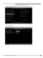
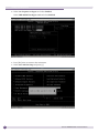
1
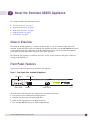
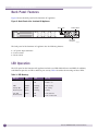
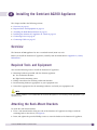
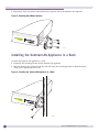
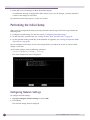
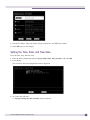
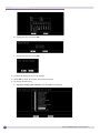
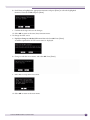
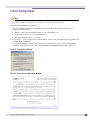
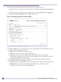
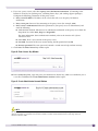
Sentriant AG200 Hardware Installation Guide
Extreme Networks, Inc.
3585 Monroe Street
Santa Clara, California 95051
(888) 257-3000
(408) 579-2800
http://www.extremenetworks.com
Published: June 2008
Part number: 100317-00 Rev. 01
AccessAdapt, Alpine, Altitude, BlackDiamond, EPICenter, ESRP, Ethernet Everywhere, Extreme Enabled, Extreme
Ethernet Everywhere, Extreme Networks, Extreme Standby Router Protocol, Extreme Turbodrive, Extreme Velocity,
ExtremeWare, ExtremeWorks, Essentials, ExtremeXOS, the Go Purple Extreme Solution, ScreenPlay, Sentriant,
ServiceWatch, Summit, SummitStack, Triumph, Unified Access Architecture, Unified Access RF Manager, UniStack,
the Extreme Networks logo, the Alpine logo, the BlackDiamond logo, the Extreme Turbodrive logo, the Summit
logos, the Powered by ExtremeXOS logo, and the Color Purple, among others, are trademarks or registered
trademarks of Extreme Networks, Inc. or its subsidiaries in the United States and/or other countries.
Adobe, Flash, and Macromedia are registered trademarks of Adobe Systems Incorporated in the U.S. and/or other
countries. AutoCell is a trademark of AutoCell. Avaya is a trademark of Avaya, Inc. Internet Explorer is a registered
trademark of Microsoft Corporation. Mozilla Firefox is a registered trademark of the Mozilla Foundation. sFlow is a
registered trademark of sFlow.org. Solaris and Java are trademarks of Sun Microsystems, Inc. in the U.S. and other
countries.
Specifications are subject to change without notice.
All other registered trademarks, trademarks, and service marks are property of their respective owners.
© 2008 Extreme Networks, Inc. All Rights Reserved.
2
Sentriant AG200 Hardware Installation Guide
Contents
Preface........................................................................................................................................... 5
About this Guide .........................................................................................................................5
Organization of this Guide............................................................................................................5
Conventions................................................................................................................................5
Related Publications ...................................................................................................................6
Chapter 1: About the Sentriant AG200 Appliance .............................................................................. 7
Chassis Overview.........................................................................................................................7
Front Panel Features ...................................................................................................................7
Back Panel Features....................................................................................................................8
LED Operation ............................................................................................................................8
LCD Panel ..................................................................................................................................9
Chapter 2: Site Preparation and Unpacking .................................................................................... 11
Site Requirements for the Sentriant AG Appliance........................................................................11
Rack Ventilation Requirements.............................................................................................11
Unpacking the Sentriant AG Appliance........................................................................................12
Chapter 3: Installing the Sentriant AG200 Appliance ....................................................................... 13
Overview ..................................................................................................................................13
Required Tools and Equipment...................................................................................................13
Attaching the Rack-Mount Brackets ............................................................................................13
Installing the Sentriant AG Appliance in a Rack ...........................................................................14
Connecting Power .....................................................................................................................15
Connecting Cables ....................................................................................................................15
Chapter 4: Startup and Configuration.............................................................................................. 17
Connecting to the Console Port...................................................................................................17
Using Console Menus ................................................................................................................17
Performing the Initial Setup .......................................................................................................18
Configuring Network Settings ...............................................................................................18
Setting the Time, Date, and Time Zone .................................................................................19
Setting the Operation Mode of the Server ..............................................................................22
Initial Configuration ..................................................................................................................23
Enabling LAN Bypass ................................................................................................................26
Appendix A: Safety Information ...................................................................................................... 29
Considerations Before Installing .................................................................................................29
Power Safety ............................................................................................................................29
Maintenance Safety...................................................................................................................30
General Safety Precautions ........................................................................................................30
Battery Replacement and Disposal..............................................................................................31
Sentriant AG200 Hardware Installation Guide
3
Contents
Appendix B: Technical Specifications ............................................................................................ 35
Index ............................................................................................................................................ 39
4
Sentriant AG200 Hardware Installation Guide
Preface
This preface provides an overview of this guide, describes guide conventions, and lists other
publications that might be useful.
About this Guide
This guide describes how to install the Sentriant AG200 appliance in an equipment rack.
Organization of this Guide
This guide includes the following chapters and appendixes:
●
About the Sentriant AG200 Appliance on page 7
●
Site Preparation and Unpacking on page 11
●
Installing the Sentriant AG200 Appliance on page 13
●
Startup and Configuration on page 17
●
Safety Information on page 29
●
Technical Specifications on page 35
Conventions
Table 1 and Table 2 list conventions used in Extreme Networks customer documentation.
Table 1: Notice Icons
Icon
Notice Type
Alerts you to...
Note
Important information, helpful suggestions, or reference material.
Caution
Risk of personal injury, system damage, or loss of data.
Warning
Risk of severe personal injury.
Sentriant AG200 Hardware Installation Guide
5
Preface
Table 2: Text Conventions
Convention
Description
Screen displays or
entered text
This typeface represents information as it appears on the screen, command syntax,
or text you enter on a command line.
The words “enter”
and “type”
When you see the word “enter” in this guide, you must type something, and then
press the Return or Enter key. Do not press the Return or Enter key when an
instruction simply says “type.”
<Key> names
Key names appear in text in one of two ways:
• Referenced by their labels, such as “the Return key” or “the Escape key”
• Written with angle brackets, such as <Enter> or <Esc>
If you must press two or more keys simultaneously, the key names are linked with a
plus sign (+). Example:
Press <Ctrl> + <Alt> +< Del>.
Words in italicized type
Italics emphasize a point of information or denote new terms at the place where
they are defined in the text.
Bold type
Graphical user interface (GUI) names and control options that appear on the
management screen.
Related Publications
For more information about configuring and using the Sentriant AG appliance, refer to the following
publications:
●
Sentriant AG Software Installation Guide, Version 5.1
●
Sentriant AG Software User Guide, Version 5.1
These guides are available in the following directory on the Sentriant AG appliance:
/usr/local/nac/webapps/ROOT/docs/UsersGuide/
The filenames for the guides are:
●
Sentriant AG Software Installation Guide: Installationguide.pdf
●
Sentriant AG Software User Guide: Usersguide.pdf
Access the document directory in either of the following ways:
●
Using the console port on the Sentriant AG appliance at any time
●
After the Sentriant AG appliance has been configured, using SSH
In addition, documentation for Extreme Networks products is available from the Extreme Networks
website at the following location:
http://www.extremenetworks.com/services/documentation
6
Sentriant AG200 Hardware Installation Guide
1
About the Sentriant AG200 Appliance
This chapter includes the following sections:
●
“Chassis Overview” on page 7
●
“Front Panel Features” on page 7
●
“Back Panel Features” on page 8
●
“LED Operation” on page 8
●
“LCD Panel” on page 9
Chassis Overview
The Sentriant AG200 appliance is a compact enclosure that is 1 RU (1.75 inches) high. It fits into a
standard 19-inch (48.26 cm) rack. The Sentriant AG appliance provides two 10/100/1000 Ethernet ports,
a serial console port, and a USB port. An LCD panel provides access for local system management.
Status LEDs provide information about port and system operation.
The Sentriant AG appliance is cooled by three fans. An AC power connector and power switch are
located on the back panel.
Front Panel Features
Figure 1 shows the front panel of the Sentriant AG appliance.
Figure 1: Front Panel of the Sentriant AG Appliance
LCD display
PWR
Console port
HDD
eth0
CONSOLE
System LEDs
USB port
eth1
Ethernet ports
SN_001
The front panel of the Sentriant AG appliance has the following features:
●
LCD panel for local configuration and diagnostics
●
USB port for connecting a standard USB drive
●
Serial console implemented as an RJ-45 connector
●
Two 10/100/1000 Ethernet ports, labeled eth0 and eth1
Sentriant AG200 Hardware Installation Guide
7
About the Sentriant AG200 Appliance
Back Panel Features
Figure 2 shows the back panel of the Sentriant AG appliance.
Figure 2: Back Panel of the Sentriant AG Appliance
Reset switch
Power switch
AC power
connector
SN_002
The back panel of the Sentriant AG appliance has the following features:
●
AC power input connector
●
Power switch
●
Reset switch
LED Operation
The LCD panel on the Sentriant AG appliance includes two LEDs labeled Power and HDD. In addition,
each Ethernet port has an LED to indicate port activity. Table 3 describes the meanings of these LEDs.
Table 3: LED Meanings
8
LED Type
Color
State
Meaning
Power
Green
Off
Power is off.
On
Power is on.
HDD
Amber
Flashing
Disk activity
Activity (On
Ethernet port)
Green
Steady
No activity
Green
Flashing
Activity
Link (On
Ethernet port)
Green
On
Link detected
Off
Link not detected
Sentriant AG200 Hardware Installation Guide
LCD Panel
The LCD panel on the Sentriant AG appliance provides identifying information for the appliance and
information about the basic system health. The information on the panel includes:
●
Hostname of the appliance
●
IP address of the appliance
●
Software version
●
Product name
●
System uptime
Sentriant AG200 Hardware Installation Guide
9
About the Sentriant AG200 Appliance
10
Sentriant AG200 Hardware Installation Guide
2
Site Preparation and Unpacking
This chapter includes the following sections:
●
“Site Requirements for the Sentriant AG Appliance” on page 11
●
“Unpacking the Sentriant AG Appliance” on page 12
Site Requirements for the Sentriant AG Appliance
The Sentriant AG200 appliance can be rack-mounted in a standard 19-inch rack.
Locate the system away from heat sources and in an area that provides unobstructed air flow to the
chassis cooling vents. The chassis intake ambient air temperature should not exceed 95 ºF (35 ºC) or
drop below 41ºF (5º C).
CAUTION
Do not place a monitor or other object on top of the system. The mounting brackets and chassis cover are not
designed to support additional weight.
Make sure that the voltage and frequency of the power source matches the electrical ratings of the
Sentriant AG appliance, and that the building and/or power source provides overload protection.
Operating humidity should be kept between 10% and 95% relative humidity (noncondensing).
In regions that are susceptible to electrical storms, we recommend that you plug your system into a
surge suppressor.
Rack Ventilation Requirements
●
Make sure that there is a minimum of 3 inches of airspace at the back of the chassis.
●
Open-type racks should meet the manufacturer’s recommended ventilation requirements.
●
Enclosed-type racks should have a louvered front and back with a fan to dissipate heat generated by
equipment mounted in the rack.
●
If you are installing the Sentriant AG appliance in enclosed racks with top-mounted ventilation fans,
make sure that there is adequate ventilation for the racks. Heat generated by equipment mounted in
the bottom of the rack can be drawn up into equipment mounted in the top of the rack.
●
Chassis intake ambient air temperature should not exceed 95º F (35º C).
Sentriant AG200 Hardware Installation Guide
11
Site Preparation and Unpacking
Unpacking the Sentriant AG Appliance
When you unpack the Sentriant AG appliance, verify that you have received the following items:
12
●
Extreme Networks Sentriant AG appliance
●
Two rack-mounting brackets
●
Eight Phillips screws (two extras) for attaching the rack-mounting brackets to the unit
●
AC power cord for use in North America
●
DB-9-to-RJ-45 serial cable for connecting the serial console port
●
Sentriant AG200 Hardware Quick Start Guide
●
Registration card
Sentriant AG200 Hardware Installation Guide
3
Installing the Sentriant AG200 Appliance
This chapter includes the following sections:
●
Overview on page 13
●
Required Tools and Equipment on page 13
●
Attaching the Rack-Mount Brackets on page 13
●
Installing the Sentriant AG Appliance in a Rack on page 14
●
Connecting Power on page 15
●
Connecting Cables on page 15
Overview
The Sentriant AG200 appliance fits into a standard 19-inch (48.26 cm) rack.
Before you install the Sentriant AG appliance, carefully read the information in Appendix A, “Safety
Information.”
Required Tools and Equipment
You need the following items to install the Sentriant AG appliance:
●
Mounting hardware provided with the Sentriant appliance
■
Two rack-mount brackets
■
Eight bracket-mounting screws
●
Phillips screwdriver for attaching rack-mount brackets
●
Rack mounting hardware appropriate to your equipment rack
●
Screwdriver appropriate for the mounting hardware used with your equipment rack
NOTE
Rack-mounting hardware is not included with the Sentriant AG appliance. Use mounting screws appropriate to your
equipment rack.
Attaching the Rack-Mount Brackets
To attach the rack-mount brackets:
1 Place a rack-mount bracket along one side of the Sentriant AG appliance and align it with the
mounting holes in the chassis (see Figure 3).
2 Insert and tighten the provided Phillips screws to secure the bracket to the Sentriant AG appliance.
Sentriant AG200 Hardware Installation Guide
13
Installing the Sentriant AG200 Appliance
3 Repeat these steps to attach the other bracket to the opposite side of the Sentriant AG appliance.
Figure 3: Attaching Rack-Mount Brackets
SN_003
Installing the Sentriant AG Appliance in a Rack
To install the Sentriant AG appliance in a rack:
1 Determine the mounting location for the Sentriant AG appliance.
2 Slide the Sentriant AG appliance into the rack and secure the mounting brackets to both front posts
using screws appropriate to the rack.
Figure 4: Installing the Sentriant AG Appliance in a Rack
SN_004
14
Sentriant AG200 Hardware Installation Guide
Connecting Power
Connect the AC power cable from the power connector on the back of the Sentriant AG appliance to an
active power outlet.
To power on the Sentriant AG appliance, press the power switch to the On position.
When the server has completed the boot process, the LCD panel displays the following information:
●
Hostname of the appliance
●
IP address of the appliance
●
Software version
●
Product name
●
System uptime
If a terminal is attached to the console port, a system prompt is displayed.
Connecting Cables
The details of connecting the Ethernet ports vary depending on the type of deployment. Deployment
types using the Sentriant AG appliance include inline, DHCP, and 802.1X deployments. For details
about the deployment options for the Sentriant AG appliance, refer to chapter 2 of the Sentriant AG
Software Installation Guide.
To connect the Ethernet ports, use Category 5 or better cable terminated in an RJ-45 connector.
Connect the port labeled eth0 to the corporate LAN (the internal network side).
Connect the port labeled eth1 to a switch or to a VPN or DHCP server (the Internet or endpoint side).
To connect the Console port to a PC or terminal server, use the provided DB-9-to-RJ-45 serial cable. For
more details, see “Connecting to the Console Port” on page 17.
Sentriant AG200 Hardware Installation Guide
15
Installing the Sentriant AG200 Appliance
16
Sentriant AG200 Hardware Installation Guide
4
Startup and Configuration
The Sentriant AG200 appliance is shipped with the latest software installed. You must connect to the
server using the console port on the front panel to configure the Sentriant AG appliance for your
network with the correct IP address, default gateway, DNS server, and other settings.
This chapter includes the following sections:
●
Connecting to the Console Port on page 17
●
Using Console Menus on page 17
●
Performing the Initial Setup on page 18
●
Initial Configuration on page 23
●
Enabling LAN Bypass on page 26
Connecting to the Console Port
Use the provided DB-9 to RJ-45 serial cable to connect the console port to a workstation running
software with console capability.
The console port has the following settings:
●
38400 baud
●
8 data bits
●
1 stop bit
●
No parity
Log in the first time using the following default values:
●
User name: root
●
Password: sentriantag
When you log in the first time, the system will prompt you to change the default password. You must
change the password before you continue with the initial setup.
Using Console Menus
The initial setup process uses a series of console menus. To use the console menus:
1 Use the arrow keys to select a menu item to change.
2 When an item is highlighted, press [Tab] to select Edit and then press [Enter].
3 Type the information for the selected item and press [Enter].
You can select and edit other items from the menu.
4 When you have finished editing items, select OK.
A message is displayed asking if you want to save the changes.
Sentriant AG200 Hardware Installation Guide
17
Startup and Configuration
5 Select Yes to save the changes or No to discard the changes.
A confirmation message is displayed for either action. If you save the changes, you must reboot the
system for the changes to take effect.
To perform the initial setup process, see the next section.
Performing the Initial Setup
After you have changed the default password, perform the initial setup. The initial setup includes the
following tasks:
●
Configure network settings (see the next section, “Configuring Network Settings.”
●
Set the time, date, and time zone (see “Setting the Time, Date, and Time Zone” on page 19.
●
Set the operation mode (personality) of the Sentriant AG appliance (see “Setting the Operation Mode
of the Server” on page 22).
You can configure each of these and save the changes before you reboot the system to activate all the
changes at one time.
At the system prompt, enter the following command:
Sentriant AG200(sentriantAG):~ #cosetup
The main configuration menu is displayed.
Configuring Network Settings
To configure network settings:
1 Highlight Configure Network Settings and select OK.
2 Press [Enter].
The network settings menu is displayed.
18
Sentriant AG200 Hardware Installation Guide
3 Edit the IP address, Netmask, Default Gateway, Hostname, and DNS Server fields.
4 Select OK and save the changes.
Setting the Time, Date, and Time Zone
To set the time, date, and time zone:
1 From the main configuration menu, highlight Adjust time, date, timezone, and select OK.
2 Press [Enter].
The main time and date configuration menu is displayed.
3 To set the date and time:
a Highlight Change the date and time and press [Enter].
Sentriant AG200 Hardware Installation Guide
19
Startup and Configuration
b Change the date and select OK.
c
Change the time and select OK.
4 Confirm the change and save the changes.
5 Select OK to return to the time/date/timezone menu.
6 To change the time zone:
a Highlight Change your timezone and select OK. Press [Enter].
20
Sentriant AG200 Hardware Installation Guide
b Scroll down to highlight the appropriate timezone and press [Enter] to select the highlighted
timezone. Then tab to OK and press [Enter].
c
Confirm the change and save the changes.
d Select OK to return to the time/date/timezone menu.
7 To change the NTP server:
a Highlight Change or edit the NTP server list and select OK. Press [Enter].
A comma-separated list of NTP server names is displayed.
b Change or edit the server names and select OK. Press [Enter].
c
Select Yes to accept the list of servers.
d Select OK to return to the main menu.
Sentriant AG200 Hardware Installation Guide
21
Startup and Configuration
Setting the Operation Mode of the Server
To set the operation mode (personality) of the server:
1 From the main menu, highlight Set personality of the Sentriant AG.
A warning message is displayed.
2 Select Yes to display the personality selection menu.
3 Highlight the appropriate server type (Management Server, Enforcement Server, or Combination
Server) and press the space bar.
A confirmation dialog box is displayed.
4 If the displayed server type is correct, select Yes. The screen indicates that services restart
immediately; then the main menu is displayed.
If the displayed server type is not correct, select No. The system returns to the previous menu.
After you select a server type as the mode of operation, you must configure specific parameters for each
type of operation. For instructions on configuring these parameters, refer to Chapter 3, “System
Configuration,” in the Sentriant AG Software User’s Guide.
22
Sentriant AG200 Hardware Installation Guide
Initial Configuration
NOTE
If endpoints are already attached to a switch when you install Sentriant AG, you must log in to each switch and
send the NAC revalidate command before the endpoint can be tested and routed properly.
To configure the Sentriant AG appliance:
1 Log in to a different computer with browser software installed. The following browsers are
supported for this release:
●
Windows: IE 6.0 or later, Mozilla Firefox v1.5 or later, Mozilla v1.7
●
Linux: Mozilla Firefox v1.5 or later, Mozilla v1.7
●
Mac OS X: Mozilla Firefox v1.5 or later
2 Using https://, point your browser to the IP address or host name of the Sentriant AG appliance (for
example, https://10.0.64.25).
3 You might be prompted with a security alert because Sentriant AG uses a secure communication
connection (SSL) (Figure 5). Click Yes. The Accept license agreement window opens (Figure 6).
Figure 5: Security Alert Window
Figure 6: Accept License Agreement Window
Sentriant AG200 Hardware Installation Guide
23
Startup and Configuration
4 Respond to the Accept license agreement window in one of the following ways:
●
If you do not wish to accept the license agreement, select I do not accept this license agreement.
or
●
Read the Sentriant AG End-User License Agreement and select I Accept this license agreement.
5 Click Next. The Enter management server settings window opens.
Figure 7: Enter Management Server Settings Window
6 The Date and time area is pre-populated with values entered during the initial installation process.
Change any of the following as necessary:
●
Region—Select a region from the drop-down list.
●
Time zone—Select a time zone from the drop-down list.
●
NTP servers—Enter one or more Network Time Protocol (NTP) servers (for example,
time.nist.gov), separated by commas. The NTP allows Sentriant AG to synchronize its date and
time with other endpoints on your network.
7 The Network settings area is pre-populated with values entered during the initial installation
process. Change any of the following as necessary:
24
●
Host name—Enter a fully qualified domain name (FQDN) (for example, crocus.mycompany.com).
●
DNS IP address—Enter one or more DNS resolver IP addresses, separated by commas,
semicolons, or spaces (for example, 10.0.16.100,10.0.1.1).
Sentriant AG200 Hardware Installation Guide
8 If you use a proxy server, select Use a proxy server for Internet connections. (Connecting to the
Internet is necessary for updating tests, validating license keys, and sending support packages.)
Configure the following parameters for the proxy server:
●
Proxy server IP address: IP address of the server that will act as the proxy for Internet
connections.
●
Proxy server port: Port used for connecting to the proxy server (for example, 8080).
●
Proxy server is authenticated: Select this parameter if your proxy server is authenticated, and
enter the following:
■
Authentication method: Scheme used to authenticate credentials on the proxy server from the
drop-down list. Select Basic, Digest, or Negotiable.
For more information about authentication methods, refer to the Sentriant AG Software
Installation Guide.
■
User name: ID of a user account on the proxy server
■
Password: Password of the user account having the ID specified in User ID
■
Re-enter password: The same password, entered a second time to help confirm accuracy
9 Click Next. The Enter license key window opens
Figure 8: Enter License Key Window
10 In the License key field, copy and paste your Sentriant AG license key, which was emailed to you as
a text file. Click Next. The Create administrator account window opens.
Figure 9: Create Administrator Account Window
NOTE
An internet connection is required to register and activate the license. The license key is registered to the server
after the activation is complete and cannot be moved to another machine without first contacting Technical
Assistance Center (TAC).
Sentriant AG200 Hardware Installation Guide
25
Startup and Configuration
CAUTION
If you use a proxy server, your license key will not validate from this window unless you have performed step 8 on
page 25.
11 Enter a User name and Password for the initial Sentriant AG administrator account. (This is not the
same as the server’s root account that you created in during installation.)
We suggest the password be at least eight characters with a mix of numbers and letters.
Click Finish.
The Sentriant AG home window opens.
Figure 10: Sentriant AG Home Window
For information about additional configuration tasks, refer to the Sentriant AG Software Installation Guide
and the Sentriant AG Software User Guide.
Enabling LAN Bypass
If the Sentriant AG appliance loses power or has a major hardware failure, the LAN bypass feature
prevents loss of network traffic. By default, LAN bypass is disabled. This section describes how to
enable LAN bypass.
CAUTION
In certain network topologies, loops can occur when LAN bypass is active. Only enable LAN bypass if the Sentriant
AG appliance is installed in an inline or DHCP inline deployment
To enable LAN bypass:
1 Connect a terminal or terminal emulator to the serial console port.
2 While the unit is powering on, press [Delete] or [Tab] to enter the BIOS.
26
Sentriant AG200 Hardware Installation Guide
3 Use the arrow keys to highlight Integrated Peripherals, and press [Enter}.
4 Select Onboard Devices.
Sentriant AG200 Hardware Installation Guide
27
Startup and Configuration
5 Select Lan 1/2 power on bypass and select Enabled.
Select PWR On/Off Lan Bypass Ctrl and select Enabled.
6 Press [Esc] twice to return to the main menu.
7 Select Save and Exit Setup and press [y]
28
Sentriant AG200 Hardware Installation Guide
A
Safety Information
WARNING!
Read the following safety information thoroughly before installing Extreme Networks products. Failure to follow this
safety information can lead to personal injury or damage to the equipment.
Only trained service personnel should perform service to Extreme Networks equipment and their
components. Trained service personnel have read all related installation manuals, have the technical
training and experience necessary to be aware of the hazards to which they are exposed in performing a
task, and are aware of measures to minimize the danger to themselves or other persons.
Considerations Before Installing
Consider the following items before installing equipment.
●
●
The system is designed to operate in a typical environmentally controlled Telco environment. Choose
an indoor area that has the following characteristics:
■
Temperature- and humidity-controlled, such that the maximum ambient room temperature shall
not exceed 95ºF (35ºC)
■
Clean and free from airborne materials that can conduct electricity (other than normal room dust)
■
Well ventilated and away from sources of heat including direct sunlight
■
Away from sources of vibration or physical shock
■
Isolated from strong electromagnetic fields produced by electrical devices
■
Secured, enclosed, and restricted-access, ensuring that only trained and qualified service
personnel have access to the equipment
Establish at least 3 inches clearance on all sides for effective ventilation. Do not obstruct the air
intake vent on the front, side, or rear ventilation grills. Locate the system away from heat sources.
Power Safety
When you connect the system to power:
●
Plug power supplies only into properly grounded electrical outlets to help prevent electrical shock
and comply with international safety standards.
●
Make sure the voltage and frequency of your power outlet match the system electrical ratings for the
equipment. The building and/or power source must provide overload protection.
●
Use only power cords that are certified for use within the country of use. Do not attempt to modify
AC power cords.
●
Use a surge suppressor, line conditioner, or uninterruptible power supply to protect the system from
momentary increases or decreases in electrical power.
Sentriant AG200 Hardware Installation Guide
29
Safety Information
WARNING!
Provided with this product is a detachable power supply cord with IEC320 style terminations for use in the US.
Before making the connection, make sure the voltage rating of the product equals or exceeds the voltage and
amperage rating of the power source. For 120-volt applications, use only a UL-listed detachable power cord with a
NEMA configuration 5-15P type (parallel blades) plug cap. For 240-volt applications use only a UL-listed detachable
power supply cord with a NEMA configuration 6015P type (tandem blades) plug cap.
Maintenance Safety
When you perform maintenance procedures on Extreme Networks equipment, follow these
recommendations:
●
Use only original accessories and/or components approved for use with this system. Failure to
follow these instructions may damage the equipment or violate required safety and EMC
regulations.
●
The chassis cover should be removed only by Extreme Networks personnel. There are no customer
serviceable components in this system. Repairs to the system must be performed by an Extreme
Networks factory service technician.
●
The power button on the system may not turn off all system AC power. To remove AC power from
the system, you must unplug the AC power cord from the wall outlet or power supply. The power
cord is the disconnect device to the main AC power source.
●
Disconnect all power cords before working near power supplies, unless otherwise instructed by a
maintenance procedure.
●
When you work with modular accessories, put on an ESD-preventive wrist strap to reduce the risk
of electronic damage to the equipment. Connect the other end of the strap to an appropriate
grounding point on the equipment rack. Leave the ESD-preventive wrist strap permanently attached
to the equipment rack so that it is always available when you need to handle ESD-sensitive
components.
●
Install all cables in a manner that avoids strain. Use tie wraps or other strain relief devices.
●
When the system is powered on, be extremely careful when measuring high voltages or when
servicing cards, panels or boards.
General Safety Precautions
Follow these guidelines:
30
●
Do not try to lift objects that you think are too heavy for you.
●
When you are installing equipment in a rack, load heavier devices in the lower half of the rack first
to avoid making the rack top-heavy.
●
Do not place a monitor or other objects on top of the equipment. The chassis cover is not designed to
support weight.
●
Only use tools and equipment that are in perfect condition. Do not use equipment with visible
damage.
●
Route cables in a manner that prevents possible damage to the cables and avoids causing accidents,
such as tripping.
Sentriant AG200 Hardware Installation Guide
Battery Replacement and Disposal
The lithium battery in this equipment is not user-replaceable. It must be replaced by qualified Extreme
Service personnel only.
Contact your Extreme Service personnel for product replacement. Do not attempt to replace the battery.
If these instructions are disregarded and replacement of these batteries is attempted, the following
guidelines must be followed to avoid danger of explosion:
●
Replace with the same or equivalent battery type as recommended by the battery manufacturer.
●
Dispose of the battery in accordance with the battery manufacturer’s recommendation.
Sentriant AG200 Hardware Installation Guide
31
Safety Information
Sicherheitshinweise
WARNUNG!
Vor der Installation der Produkte von Extreme Networks sind die nachfolgenden Sicherheitshinweise aufmerksam zu
lesen. Die Nichtbeachtung dieser Sicherheitshinweise kann zu Verletzungen oder Schäden an der Ausrüstung führen.
Installation, Wartung und Ausbau eines Switch, einer Grundplatte oder einer seiner Komponenten
dürfen nur von geschultem und qualifiziertem Servicepersonal durchgeführt werden! Geschulte und
qualifizierte Servicetechniker verfügen über die erforderliche technische Ausbildung und Erfahrung, um
mögliche Gefahren bei der Durchführung von Servicearbeiten zu erkennen und Maßnahmen zur
Minimierung der Gefahr für sich bzw. andere zu treffen.
Hinweise zur Installation
WARNUNG!
Beachten Sie vor der Installation der Ausrüstung folgende Punkte.
Stellen Sie sicher, dass die nachfolgend aufgeführten Bedingungen erfüllt sind:
●
32
Das System ist für den Einsatz in einer typischen Umgebung gemäß Telco-Vorgaben vorgesehen.
Wählen Sie einen Aufstellort mit den folgenden Eigenschaften:
■
Innenbereich mit Temperatur- und Feuchtigkeitsregelung, wobei die maximale Raumtemperatur
40°C (104ºF) nicht überschreiten darf.
■
Sauber und frei von elektrisch aufladbaren Teilchen in der Luft.
■
Ausreichende Belüftung und Abstand zu Wärmequellen, einschließlich direktem Sonnenlicht
■
Ausreichender Abstand zu Quellen, die Erschütterungen oder Schläge/Stöße hervorrufen können
■
Isolierung von starken elektromagnetischen Feldern, wie sie durch Elektrogeräte erzeugt werden
■
Sicherer, abgeschlossener Arbeitsbereich mit beschränktem Zugang, sodass nur geschultes und
qualifiziertes Servicepersonal Zugriff auf das Gerät hat
■
In für elektrische Stürme anfälligen Gebieten wird empfohlen, das System an einen
Spannungsstoßunterdrücker anzuschließen.
●
Auf allen Seiten für mindestens 7,5 cm (3") Abstand sorgen, um eine ausreichende Belüftung zu
gewährleisten. Die Lufteinlassöffnung an den vorderen, seitlichen und hinteren Entlüftungsgittern
nicht blockieren. Das System nicht in der Nähe von Wärmequellen aufstellen.
●
Die Ausrüstung im unteren Teil des Gestells installieren, um zu vermeiden, dass der obere Teil des
Gestells zu schwer wird.
Sentriant AG200 Hardware Installation Guide
Warnhinweise
●
Das System an vorschriftsmäßig geerdete Steckdosen anschließen, um die Gefahr elektrischer
Schläge zu vermeiden. Die Steckdose muss in der Nähe der Anlage installiert und leicht zugänglich
sein, um eine schnelle Trennung vom Netz zu ermöglichen.
●
Sicherstellen, dass Spannung und Frequenz der Steckdose den elektrischen Nenndaten des Systems
entsprechen. Das Gebäude bzw. die Stromquelle muss mit einem Überlastschutz ausgestattet sein.
●
Nur Stromkabel verwenden, die für den Einsatz in dem jeweiligen Land zugelassen sind.
Wechselstromkabel dürfen nicht manipuliert werden. Stromkabel bei Anzeichen von
Beschädigungen unverzüglich austauschen.
●
Einen Spannungsstoßunterdrücker, einen Netzfilter oder eine unterbrechungsfreie Stromversorgung
verwenden, um das System vor einer vorübergehenden Zu- oder Abnahme der elektrischen Leistung
zu schützen.
Wartungssicherheit
●
Nur für den Einsatz mit diesem System zugelassene Originalzubehörteile bzw. Komponenten
verwenden. Die Nichtbeachtung dieser Anweisungen kann zu Schäden an der Ausrüstung oder
sogar zu einem Verstoß gegen die erforderlichen Sicherheitsbestimmungen und EMV-Vorschriften
führen.
●
Die Abdeckung der Grundplatte darf nur durch Personal von Extreme Networks entfernt werden.
Das System enthält keine vom Kunden zu wartenden Komponenten. Reparaturen am System sind
von einem Extreme Networks Servicetechniker durchzuführen.
●
Der An-/Aus-Schalter des Systems unterbricht nicht die Wechselstromversorgung zum System. Zur
Unterbrechung der Wechselstromversorgung zum System muss das Wechselstromkabel aus der
Wandsteckdose oder der Stromquelle gezogen werden. Das Stromkabel dient zur Trennung von der
Netz-/Wechselstromversorgung.
●
Vor der Aufnahme von Arbeiten in der Nähe von Stromquellen alle Stromkabel abziehen, sofern
nicht im Rahmen eines Wartungsverfahrens anders vorgegeben.
●
Schutz elektrostatisch gefährdeter Bauelemente (EGB): Zum Schutz elektrostatisch gefährdeter
Bauelemente (EGB) grundsätzlich vor der Aufnahme von Arbeiten an Leiterplatten oder Modulen
ein Armband anlegen. Leiterplatten nur in antistatischer Verpackung transportieren. Vor der
Aufnahme von Arbeiten an Leiterplatten diese immer auf einer geerdeten Fläche ablegen.
●
Alle Kabel so verlegen, dass übermäßige Belastungen vermieden werden. Kabelbinder oder
Zugentlastungsklemmen verwenden.
Allgemeine Sicherheitsmaßnahmen:
Folgende Richtlinien sind unbedingt zu befolgen:
●
Keine Gegenstände heben, die möglicherweise zu schwer sind.
●
Bei der Messung hoher Spannungen und der Wartung von Karten, Konsolen oder Leiterplatten bei
eingeschaltetem System extreme Vorsicht walten lassen.
●
Keinen Monitor oder andere Gegenstände auf die Anlage stellen. Die Abdeckung der Grundplatte ist
nicht darauf ausgelegt, Gewicht zu tragen.
●
Nur Werkzeuge und Ausrüstung verwenden, die sich in einwandfreiem Zustand befinden. Keine
Ausrüstung verwenden, die sichtbare Beschädigungen aufweist.
Sentriant AG200 Hardware Installation Guide
33
Safety Information
●
Verlegen von Kabeln: Kabel so verlegen, dass keine Schäden entstehen oder Unfälle, z. B. durch
Stolpern, verursacht werden können.
●
Bei einer Installation in einem Gestell darauf achten, dass schwere Geräte unten im Gestell eingebaut
werden, um Gefahren durch Umkippen zu vermeiden.
Austauschen und Entsorgen von Batterien
●
34
Austauschen der Lithium-Batterie: Die Batterie kann nicht vom Anwender ausgetauscht werden. Die
Batterien dürfen nur durch eine identische oder eine gleichwertige, vom Hersteller empfohlene
Batterie ersetzt werden. Hierbei ist vorsichtig vorzugehen, da bei einem unsachgemäßen Austausch
der Lithium-Batterie Explosionsgefahr besteht.
Sentriant AG200 Hardware Installation Guide
B
Technical Specifications
Table 4 provides technical specifications for the Sentriant AG200 appliance.
Table 4: Sentriant AG Appliance Technical Specifications
Physical Specifications
Chassis dimensions
Height: 1.7 inches (4.3 cm)
Width: 17 inches (43.2 cm)
Depth: 17.3 inches (43.9 cm)
Weight
21 lb (9.5 kg)
Power Input
Voltage ranging
90-254 V AC
Nominal voltage range:
100-240 V AC
Line frequency range
47-63 Hz
Maximum input current
2.4A @ 100 V AC
1.2A @ 200 V AC
Power Cord
North America power supply cord provided with equipment.
Power supply cords used outside the US require country-specific certifications
as required by country standards.
Input socket
IEC 60320 C13
Wire size
0.75 mm2 (18 AWG) copper stranded
Maximum length
10 ft (3.05 m)
Safety Standards
North American Safety of ITE
ULus Listed Device UL 60950-1:2003 1st Edition
cUL to CSA C22.2 No.60950-1-03 1st Edition
European Safety of ITE
73/23/EEC Low Voltage Directive (LVD)
EN60950-1:2001+A11
TUV-R GS Mark
DEMKO
International Safety of ITE
IEC 60950-1:2001 1st Edition with all applicable country deviations
ANATEL, Safety Resolution 238 (Brazil)
NOM/NYCE (Mexico)
EMI/EMC Standards
North American EMC for ITE
FCC 47 CFR Part 15, Subpart B, Class A
ICES-003, Class A
Sentriant AG200 Hardware Installation Guide
35
Technical Specifications
Table 4: Sentriant AG Appliance Technical Specifications (Continued)
European EMC for ITE
89/336/EEC EMC Directive
EN 55022:1998 A2:2003 Class A
EN55024:1998 A2:2003 includes IEC/EN61000-2,3,4,5,6,11
EN61000-3-2:2000 Class A (Harmonics)
EN61000-3-3:1995 A1:2001 (Flicker)
ETSI/EN 300 386:v1.3.3, 2005-04 (EMC Telecommunications)
International EMC for ITE
CISPR22:1998 with A1 and A2 (Emissions)
CISPR24:1998 (Immunity)
IEC/EN 61000-4-2 Electrostatic Discharge, 8 kV Contact, 15 kV Air,
Critieria A
IEC/EN 61000-4-3 Radiated Immunity, 10 V/m, Criteria A
IEC/EN 61000-4-4 Transient Burst, 1kV, Criteria A
IEC/EN 61000-4-5 Surge, 2 kV L-L, 4 kV L-G, Level 4, Criteria A
IEC/EN 61000-4-6 Conducted Immunity, 0.15–80 MHz, 10 V/m, mod. RMS,
Criteria A
IEC/EN 61000-4-8 Magnetic Susceptibility, Criteria A
IEC/EN 61000-4-11 Power Dips & Interruptions, >30%,25 periods, Criteria C
Country-specific
VCCI Class A (Japan Emissions)
ACMA, CISPR22:2006 or AS/NZS 3548 (Australia/New Zealand)
BSMI, CNS 13438:1997, Class A (-Taiwan)
ANATEL, EMC Resolution 237 (Brazil)
MIC Mark by RLL (South Korea)
Environmental Specifications
Environmental Standards
EN/ETSI 300 019-2-1 v2.1.2 (2000–09) - Class 1.2 Storage
EN/ETSI 300 019-2-2 v2.1.2 (1999–09) - Class 2.3 Public Transportation
EN/ETSI 300 019-2-3 v2.1.2 (2003–04) - Class 3.1e Stationary Use
EN/ETSI 300 753 (1997-10) - Acoustic Noise
Green Compliance Standards
RoHS 6 compliant
China RoHs compliant
WEEE compliant
Operating conditions
Operating temperature range: 0 C to +40 C (32º F to 104º F)
Operating humidity: 10 – 90% relative humidity
Operating altitude: 0 – 3000 meters (10,000 ft)
Operating shock*: 30 m/s2 (3g), 11 ms
Operational random vibration*: 5 – 500 Hz @ 1.5Grms
Acoustic noise: < 5.5 bels A sound power per ISO 7779
< 45.0 dBA declared sound pressure
36
Sentriant AG200 Hardware Installation Guide
Table 4: Sentriant AG Appliance Technical Specifications (Continued)
Storage and transportation
conditions (packaged)
Temperature*: –40º C to +70º C (–40º F to 158º F)
Relative humidity*: 10–93% RH
Shock*: 180 m/s2 (18g), 6ms600 shocks (package < 50 kg)
Random vibration*: 5–20 Hz @ 1.0 ASD w/–3 dB/oct. from 20–200 Hz
Sinusoidal vibration: 5–62 Hz @ Velocity 5 mm/s, 62–500 Hz @ .2G
Drop*: 42.4
* Short-term test condition. Not for extended use under this condition.
Sentriant AG200 Hardware Installation Guide
37
Technical Specifications
38
Sentriant AG200 Hardware Installation Guide
Index
A
P
ambient temperature, 11
package contents, 12
physical specifications, 35
power
connecting, 15
power cord selection, 29
power safety, 29
power specifications, 35
B
battery disposal requirement, 31
C
cable routing, 30
connecting power, 15
conventions
notice icons, 5
text, 6
D
dimensions, 35
E
EMI/EMC standards, 35
enclosed rack requirements, 11
environmental requirements, 11
environmental specifications, 36
ESD protection, 30
R
rack installation
procedure, 14
requirements
environmental, 11
S
safety information, 29
safety standards, 35
site preparation, 11
surge suppressor, 11, 29
T
G
Telco environment requirements, 29
temperature, ambient, 11
text conventions, 6
German safety information, 32
green compliance standards, 36
W
H
weight, 35
humidity requirements, 11
I
installation, Sentriant NG appliance, 14
M
maintenance safety, 30
O
open rack requirements, 11
Sentriant AG200 Hardware Installation Guide
39
Index
40
Sentriant AG200 Hardware Installation Guide


![[資料3-47]](http://vs1.manualzilla.com/store/data/006687542_3-e4ddaa7f44a33ea367ea764cf00a313b-150x150.png)