1
User’s Guide
PRIMERGY BX900/BX400
Blade Server Systems
Ethernet Connection Blade Module SB6 / SB11a / SB11
IBP Version
English
PRIMERGY BX400/BX900 Connection Blades
Ethernet Connection Blades
PY CB Eth Switch/IBP 1Gb 18/6
(SB6)
PY CB Eth Switch/IBP 1Gb 36/12 (SB11a)
PY CB Eth Switch/IBP 1Gb 36/8+2 (SB11)
User’s Guide
IBP version
Edition July 2011
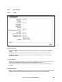
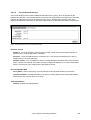
Comments… Suggestions… Corrections…
The User documentation Department would like to know your opinion on this manual. Your feedback
helps us to optimize our documentation to suit your individual needs.
Fax forms for sending us your comments are included at the back of the manual.
There you will also find the addresses of the relevant User documentation Department.
© 2011 Fujitsu Technology Solutions
2
Copyright and Trademarks
Copyright © 2011 Fujitsu Technology Solutions GmbH.
All rights reserved.
Delivery subject to availability; right of technical modifications reserved.
All hardware and software names used are trademarks of their respective manufacturers
© 2011 Fujitsu Technology Solutions
3
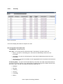
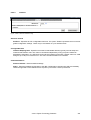
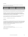
Document History
Revision
0.1
Date
12/22/2008
02.
0.3
0.4
1/9/2009
3/12/2009
1/20/2011
0.5
7/29/2011
Editor
Switch Team
Moore C. J. Lee
Moore C. J. Lee
Moore C. J. Lee
Switch Team
Moore C. J. Lee
Moore C. J. Lee
0.55
1/19/2012
E.Schröer
Remark
1st Draft
Separate into IBP version
Review & Correct
New revision
IP Filter, Storm control, errdisable
recovery and Extended VLAN group
Merged SB6/SB11a/SB11
© 2011 Fujitsu Technology Solutions
4
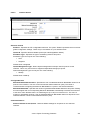
Contents
1
1.1
1.2
Important Notes.......................................................................................................11
Information About Boards..........................................................................................11
Compliance Statements ............................................................................................12
2
2.1
2.1.1
2.1.2
2.1.3
2.1.4
2.1.5
2.2
2.2.1
2.2.2
2.2.3
2.2.4
2.2.5
2.2.6
2.2.7
2.2.8
2.3
2.4
2.5
Introduction .............................................................................................................15
Features of the Ethernet Connection Blade ...............................................................17
MAC Address Supported Features ............................................................................18
Layer 2+ Features .....................................................................................................19
Management Features of Ethernet Connection Blade Module ..................................24
Security Feature ........................................................................................................28
Quality of Service Features .......................................................................................30
Description of Hardware ............................................................................................32
Port Configurations of Ethernet Connection Blade Module ........................................32
Ethernet Ports ...........................................................................................................34
Status of LEDs ..........................................................................................................35
Supported SFP and SFP+ Vendor List .................................................................37
Features and Benefits ...............................................................................................38
Connectivity ..............................................................................................................38
Performance .............................................................................................................38
Management .............................................................................................................38
Notational Conventions .............................................................................................39
Target Group.............................................................................................................39
Technical Data ..........................................................................................................40
3
3.1
3.2
3.2.1
3.2.2
Network Planning ....................................................................................................41
Introduction to IBP.....................................................................................................41
Sample Applications..................................................................................................42
Backbone Connection ...............................................................................................42
Making IBP Connections ...........................................................................................43
4
4.1
4.2
4.2.1
4.2.2
4.2.3
Making Network Connections ................................................................................44
Connecting to 1000BASE-T Devices .........................................................................44
1000BASE-T Cable Requirements ............................................................................45
Cable Testing for Existing Category 5 Cable .............................................................45
Adjusting Existing Category 5 Cabling for 1000BASE-T ............................................45
1000BASE-T Pin Assignments ..................................................................................46
5
5.1
5.2
5.3
5.4
5.5
5.6
5.6.1
5.6.2
5.7
Configuring Ethernet Connection Blade Module ..................................................47
Overview ...................................................................................................................47
Connecting the Ethernet Connection Blade Module ..................................................48
Start up and Configuration the Ethernet Connection Blade Module ...........................50
Configuring the Terminal ...........................................................................................52
Booting Device ..........................................................................................................53
Software Download ...................................................................................................54
In BootROM Back Door CLI ......................................................................................54
In Operation Code CLI ..............................................................................................56
Switching the Software Booting Mode .......................................................................58
6
6.1
6.2
6.3
6.4
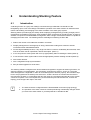
Understanding Stacking Feature ...........................................................................59
Introduction ...............................................................................................................59
Stacking Function Features Overview .......................................................................60
Stack Master Election Processes ..............................................................................61
Firmware Upgrade/Distribution Processes ................................................................62
© 2011 Fujitsu Technology Solutions
5
6.5
6.6
6.7
6.7.1
6.7.2
6.8
Powering Considerations ..........................................................................................63
Provisioning Stack Members .....................................................................................66
Naming Scheme .......................................................................................................68
IBP Name .................................................................................................................68
Naming/Addressing within a Stack ............................................................................68
Persistent MAC Address ...........................................................................................69
7
E-Keying Function Feature .....................................................................................70
8
8.1
8.1.1
8.2
8.2.1
8.2.2
8.2.3
8.2.4
8.2.5
8.2.6
8.2.7
8.2.8
8.2.9
8.2.10
8.2.11
8.2.12
8.2.13
8.2.14
8.2.15
8.3
8.3.1
8.3.2
8.3.3
8.3.4
8.3.5
8.3.6
8.3.7
8.3.8
8.3.9
8.3.10
8.4
8.4.1
8.4.2
8.4.3
8.4.4
8.4.5
8.4.6
8.4.7
8.4.8
8.4.9
8.4.10
8.4.11
8.5
8.5.1
8.5.2
8.6
8.6.1
8.6.2
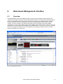
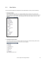
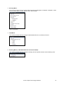
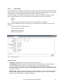
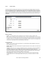
Web-based Management Interface.........................................................................71
Overview ...................................................................................................................71
Menu Options............................................................................................................72
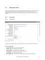
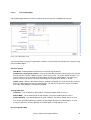
Management Menu ...................................................................................................74
Information ................................................................................................................74
Configuration.............................................................................................................76
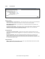
System Utilities .........................................................................................................88
File Management ......................................................................................................93
User Management................................................................................................... 100
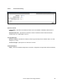
Logging ...................................................................................................................106
Statistics ................................................................................................................. 115
SNMP ..................................................................................................................... 124
SNTP ...................................................................................................................... 135
UDLD ...................................................................................................................... 144
LLDP ....................................................................................................................... 146
DHCP Client............................................................................................................ 157
DNS Relay .............................................................................................................. 159
IPv6......................................................................................................................... 164
sFlow ...................................................................................................................... 168
Group Administration Menu ..................................................................................... 173
Group List ............................................................................................................... 173
Uplink Sets .............................................................................................................. 175
Port Groups............................................................................................................. 178
VLAN Port Groups .................................................................................................. 181
Service LAN ............................................................................................................ 184
Service VLAN.......................................................................................................... 186
Auto VLAN .............................................................................................................. 188
Port .........................................................................................................................190
Port Channel ...........................................................................................................197
Port Backup ............................................................................................................ 200
Security Menu ......................................................................................................... 202
Port Access Control ................................................................................................ 202
Port Security ........................................................................................................... 213
RADIUS Configuration ............................................................................................ 218
RADIUS Statistics ................................................................................................... 224
TACACS+ ............................................................................................................... 229
LDAP ...................................................................................................................... 232
Access Control Lists................................................................................................ 233
IP Filter ................................................................................................................... 245
Secure HTTP .......................................................................................................... 247
Secure Shell............................................................................................................ 249
Denial-of-Service..................................................................................................... 250
QoS Menu ...............................................................................................................252
Differentiated Services ............................................................................................ 252
Class of Service ...................................................................................................... 268
Stacking Menu ........................................................................................................276
Configuration........................................................................................................... 276
Information .............................................................................................................. 280
© 2011 Fujitsu Technology Solutions
6
9
9.1
9.2
9.3
9.3.1
9.3.2
9.3.3
9.3.4
9.3.5
9.3.6
9.3.7
9.3.8
9.3.9
9.3.10
9.4
9.4.1
9.4.2
9.4.3
9.4.4
9.4.5
9.4.6
9.4.7
9.4.8
9.5
9.5.1
9.5.2
9.5.3
9.5.4
9.5.5
9.5.6
9.5.7
9.5.8
9.5.9
9.5.10
9.5.11
9.5.12
9.5.13
9.5.14
9.5.15
9.5.16
9.5.17
9.6
9.6.1
9.6.2
9.6.3
9.6.4
9.7
9.7.1
9.7.2
9.7.3
9.7.4
9.8
9.8.1
9.8.2
9.8.3
9.8.4
9.8.5
9.8.6
Command Reference ............................................................................................ 283
CLI Command Format ............................................................................................. 283
CLI Mode-based Topology ...................................................................................... 284
System Information and Statistic Commands .......................................................... 286
show arp ................................................................................................................. 286
show calendar .........................................................................................................286
show eventlog ......................................................................................................... 287
show running-config ................................................................................................287
show sysinfo ........................................................................................................... 288
show system ........................................................................................................... 289
show hardware ........................................................................................................ 290
show version ........................................................................................................... 291
show tech-support ................................................................................................... 292
show loginsession ................................................................................................... 292
Device Configuration Commands ............................................................................ 293
Interface .................................................................................................................. 293
L2 MAC Address and Multicast Forwarding Database Tables ................................. 309
IGMP / MLD Snooping ............................................................................................ 315
Port Channel ...........................................................................................................317
Storm Control .......................................................................................................... 328
Error Disable Recovery ........................................................................................... 337
L2 Priority ................................................................................................................ 339
Port Mirror ............................................................................................................... 341
Management Commands ........................................................................................ 344
Network Commands................................................................................................ 344
Serial Interface Commands ..................................................................................... 355
Telnet Session Commands ..................................................................................... 362
SSH Client Session Commands .............................................................................. 369
SNMP Server Commands ....................................................................................... 372
SNMP Trap Commands .......................................................................................... 384
SNMP Inform Commands ....................................................................................... 388
HTTP commands ....................................................................................................391
Secure Shell (SSH) Commands .............................................................................. 396
DHCP Client Commands......................................................................................... 399
DHCPv6 Client Commands ..................................................................................... 400
Domain Name Server Relay Commands ................................................................. 402
Dynamic DNS Client Commands ............................................................................ 410
IPv6 Commands .....................................................................................................412
UDLD Commands ................................................................................................... 418
LLDP Commands .................................................................................................... 422
sFlow Commands ................................................................................................... 436
System Log Management Commands ....................................................................443
Show Commands ....................................................................................................443
show logging buffered ............................................................................................. 444
show logging traplog ............................................................................................... 445
Configuration Commands........................................................................................ 447
Script Management Commands .............................................................................. 453
script apply ..............................................................................................................453
script delete............................................................................................................. 453
script list ..................................................................................................................454
script show .............................................................................................................. 454
System Utilities .......................................................................................................455
clear ........................................................................................................................455
copy ........................................................................................................................ 466
delete ...................................................................................................................... 470
dir ............................................................................................................................ 471
whichboot ................................................................................................................472
boot-system ............................................................................................................473
© 2011 Fujitsu Technology Solutions
7
9.8.7
9.8.8
9.8.9
9.8.10
9.8.11
9.8.12
9.8.13
9.8.14
9.8.15
9.8.16
9.8.17
9.8.18
9.9
9.9.1
9.9.2
9.10
9.10.1
9.10.2
9.11
9.11.1
9.11.2
9.12
9.12.1
9.12.2
9.13
9.13.1
9.13.2
9.14
9.14.1
9.14.2
9.15
9.15.1
9.15.2
9.16
9.16.1
9.17
9.17.1
9.17.2
9.17.3
9.17.4
9.18
9.18.1
9.18.2
9.19
9.19.1
9.19.2
9.20
9.20.1
9.20.2
9.21
9.21.1
9.21.2
9.21.3
9.21.4
9.21.5
9.21.6
9.21.7
9.21.8
classic-view ............................................................................................................. 473
ping .........................................................................................................................474
traceroute ................................................................................................................ 476
logging cli-command ............................................................................................... 477
calendar set ............................................................................................................477
reload ...................................................................................................................... 478
configure ................................................................................................................. 478
disconnect ...............................................................................................................479
hostname ................................................................................................................ 479
pager....................................................................................................................... 480
do ............................................................................................................................481
quit ..........................................................................................................................481
User Account Management Commands ..................................................................482
Show Commands ....................................................................................................482
Configuration Commands........................................................................................ 485
Privilege Level Command ....................................................................................... 489
Show commands.....................................................................................................490
Configuration Commands........................................................................................ 491
Uplink Set Commands ............................................................................................ 494
Show Commands ....................................................................................................494
Configuration Commands........................................................................................ 495
Port Group Commands ........................................................................................... 496
Show Commands ....................................................................................................496
Configuration Commands........................................................................................ 497
VLAN Port Group Commands ................................................................................. 499
Show Commands ....................................................................................................499
Configuration Commands........................................................................................ 500
Service LAN Commands ......................................................................................... 503
Show Commands ....................................................................................................503
Configuration Commands........................................................................................ 504
Service VLAN Commands....................................................................................... 505
Show Commands ....................................................................................................505
Configuration Commands........................................................................................ 506
Isolation Commands ............................................................................................... 507
Configuration Commands........................................................................................ 507
Lock Commands .....................................................................................................508
lock .........................................................................................................................508
lock_message ......................................................................................................... 509
lock_reset ............................................................................................................... 509
show lock ................................................................................................................ 510
Port Backup ............................................................................................................ 511
Show Commands ....................................................................................................511
Configuration Commands........................................................................................ 512
Link State Commands ............................................................................................. 514
Show Commands ....................................................................................................514
Configuration Commands........................................................................................ 515
SNTP Commands ................................................................................................... 516
Show Commands ....................................................................................................516
Configuration Commands........................................................................................ 519
Security Commands ................................................................................................ 525
Show Commands ....................................................................................................525
Configuration Commands........................................................................................ 536
Dot1x Configuration Commands ............................................................................. 538
Radius Configuration Commands............................................................................ 544
TACACS+ Configuration Commands ......................................................................549
Port Security Configuration Commands ..................................................................553
LDAP Commands ................................................................................................... 556
Denial of Service (DoS) Commands ........................................................................559
© 2011 Fujitsu Technology Solutions
8
9.22
9.22.1
9.22.2
9.22.3
9.22.4
9.22.5
9.23
9.23.1
9.23.2
9.24
9.24.1
9.24.2
9.25
9.25.1
9.25.2
Differentiated Service Commands ...........................................................................564
General Commands ................................................................................................ 565
Class Commands .................................................................................................... 567
Policy Commands ................................................................................................... 581
Service Commands ................................................................................................. 589
Show Commands ....................................................................................................592
ACL Commands ......................................................................................................601
Show Commands ....................................................................................................601
Configuration Commands........................................................................................ 605
CoS Commands ......................................................................................................612
Show Commands ....................................................................................................612
Configuration Commands........................................................................................ 616
Stacking Commands ............................................................................................... 624
Show Commands ....................................................................................................624
Configuration Commands........................................................................................ 627
10
10.1
10.2
10.3
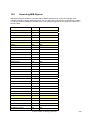
Using SNMP........................................................................................................... 630
Supported MIBs ......................................................................................................631
Accessing MIB Objects ........................................................................................... 633
Supported Traps .....................................................................................................635
© 2011 Fujitsu Technology Solutions
9
© 2011 Fujitsu Technology Solutions
10
1
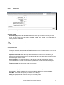
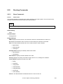
Important Notes
Store this manual close to the device. If you pass the device on to third parties, you should pass this
manual on with it. Be sure to read this page carefully and note the information before you open the
device. You cannot access the switch blade without first opening the device. Please observe the safety
information provided in the “Important Notes” chapter in this user’s guide. Components can become very
hot during operation. Ensure you do not touch components when handling the device. There is a danger
of burns! The warranty is invalidated if the device is damaged during the installation.
1.1
Information About Boards
To prevent damage to the device or the components and conductors on it, please take great care when
you insert or remove it. Take great care to ensure that the board is slotted in straight, without damaging
components or conductors on it, or any other components. Be especially careful with the locking
mechanisms (catches, centering pins etc.) when you replace the board.
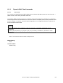
Never use sharp objects (screwdrivers) for leverage. Boards with electrostatic sensitive devices (ESD)
are identifiable by the label shown. When you handle boards fitted with ESDs, you must, under all
circumstances, observe the following points:
−
You must always discharge static build up (e.g., by touching a grounded object) before working.
−
The equipment and tools you use must be free of static charges.
−
Remove the power plug from the mains supply before inserting or removing boards containing
ESDs.
−
Always hold boards with ESDs by their edges.
−
Never touch pins or conductors on boards fitted with ESDs.
© 2011 Fujitsu Technology Solutions
11
1.2
Compliance Statements
FCC Class A Compliance
This equipment has been tested and found to comply with the limits for a “Class A” digital device,
pursuant to Part 15 of the FCC rules and meets all requirements of the Canadian Interference-Causing
Equipment Regulations. These limits are designed to provide reasonable protection against harmful
interference in a residential installation. This equipment generates uses and can radiate radio frequency
energy and, if not installed and used in strict accordance with the instructions, may cause harmful
interference to radio communications. However, there is no guarantee that interference will not occur in
a particular installation. If this equipment does cause harmful interference to radio or television
reception, which can be determined by turning the equipment off and on, the user is encouraged to try to
correct the interference by one or more of the following measures:
−
Reorient or relocate the receiving antenna.
−
Increase the separation between equipment and the receiver.
−
Connect the equipment into an outlet on a circuit different from that to which the receiver is
connected.
−
Consult the dealer or an experienced radio/TV technician for help.
Fujitsu Technology Solutions is not responsible for any radio or television interference caused by
unauthorized modifications of this equipment or the substitution or attachment of connecting cables and
equipment other than those specified by Fujitsu Technology Solutions. The correction of interferences
caused by such unauthorized modification, substitution or attachment will be the responsibility of the
user.
You may use unshielded twisted-pair (UTP) cables for RJ-45 connections – Category 3 or greater for 10
Mbps connections, Category 5 for 100 Mbps connections, and Category 5 or 5e for 1000 Mbps
connections.
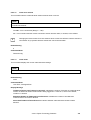
!
Wear an anti-static wrist strap or take other suitable measures to prevent electrostatic
discharge when handling this equipment.
Industry Canada - Class A
This digital apparatus does not exceed the Class A limits for radio noise emissions from digital apparatus
as set out in the interference-causing equipment standard entitled “Digital Apparatus,” ICES-003 of the
Department of Communications.
Cet appareil numérique respecte les limites de bruits radioélectriques appli- cables aux appareils
numériques de Classe A prescrites dans la norme sur le matériel brouilleur: “Appareils Numériques,”
NMB-003 édictée par le ministère des Communications.
© 2011 Fujitsu Technology Solutions
12
Japan VCCI Class A
CE Mark Declaration of Conformance for EMI and Safety (EEC)
This information technology equipment complies with the requirements of the Council Directive
89/336/EEC on the Approximation of the laws of the Member States relating to Electromagnetic
Compatibility and 73/23/EEC for electrical equipment used within certain voltage limits and the
Amendment Directive 93/68/EEC. For the evaluation of the compliance with these Directives, the
following standards were applied:
• RFI Emission:
•
•
−
Limit class A according to EN 55022:1998
−
Limit class A for harmonic current emission according to EN 61000-3-2/2006
−
Limitation of voltage fluctuation and flicker in low-voltage supply system according to EN
61000-3-3/1995
Immunity:
−
Product family standard according to EN 55024:1998
−
Electrostatic Discharge according to EN 61000-4-2:1995 (Contact Discharge: ±8 kV, Air
Discharge: ±8 kV)
−
Radio-frequency electromagnetic field according to EN 61000-4-3:1995 (80 - 1000 MHz with
1 kHz AM 80% Modulation: 3 V/m)
−
Electrical fast transient/burst according to EN 61000-4-4:2004 (AC/DC power supply: ±1 kV,
Data/Signal lines: ±0.5 kV)
−
Surge immunity test according to EN 61000-4-5:1995 (AC/DC Line to Line: ±1 kV, AC/DC
Line to Earth: ±2 kV)
−
Immunity to conducted disturbances, Induced by radio-frequency fields: EN 61000-4-6:1996
(0.15 - 80 MHz with 1 kHz AM 80% Modulation: 3 V/m)
−
Power frequency magnetic field immunity test according to EN 61000-4-8:1993 (1 A/m at
frequency 50 Hz)
−
Voltage dips, short interruptions and voltage variations immunity test according to EN
61000-4-11:1994 (>95% Reduction @10 ms, 30% Reduction @500 ms, >95% Reduction
@5000 ms)
LVD:
−
!
EN 60950 (A1/1992; A2/1993; A3/1993; A4/1995; A11/1997)
Do not plug a phone jack connector in the RJ-45 port. This may damage this device. Les
raccordeurs ne sont pas utilisé pour le système télépho- nique!
© 2011 Fujitsu Technology Solutions
13
Taiwan BSMI Class A
Australia AS/NZS 3548 (1995) - Class A
© 2011 Fujitsu Technology Solutions
14
2
Introduction
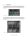
The PRIMERGY BX400 Blade Server system is a modular server system that can integrate up to 8
server modules, 4 Connection Blade Modules and two Management Modules (MMB). The Ethernet
Connection Blade Module provides networking and Switch functions to PRIMERGY BX400 Blade Server
system. The Management Module provides a single point of control for the PRIMERGY BX400 Blade
Server system.
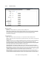
Figure: Rear view of BX400 Blade Server System
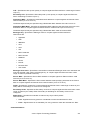
The PRIMERGY BX900 Blade Server system is a modular server system that can integrates up to 18
server modules, eight Connection Blade Modules and two Management Modules (MMB). The Ethernet
Connection Blade Module provides networking and Switch functions to PRIMERGY BX900 Blade Server
system. The Management Module provides a single point of control for the PRIMERGY BX900 Blade
Server system.
Figure: Rear view of BX900 Blade Server System
© 2011 Fujitsu Technology Solutions
15
Ethernet Connection Blade Module are designed for the Primergy new generation Blade Sever System.
There are three type connection blades as follow:
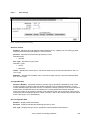
a) SB11 is a 46-port 1GbE with 2 10GbE SFP+ uplinks Layer-2+ stackable Ethernet Connection Blade.
The Ethernet Connection Blade configuration is 36 downlink ports to mid-plane and 8 1GbE with
RJ45 connectors and 2 10GbE SFP+ for uplink ports. In the BX400 Blade Server System only up to
32 of the 36 downlink ports are utilized. The full 36 downlink ports will be used in BX900 system
environment only. There are two HiGig/HiGig+ ports, one is connected to mid-plane, and the other is
on the rear panel of the Ethernet Connection Blade providing the stacking function. The Stacking
module will support to connect up to 8 SB11 devices.
Figure: PRIMERGY BX900 /BX400 GbE Connection Blade 36/8+2 Stacking (SB11) Front Panel
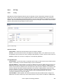
b) SB11a is a 48-port 1GbE with 4 1GbE SFP uplinks Layer-2+ Ethernet Connection Blade. The
Ethernet Connection Blade configuration is 36 downlink ports to mid-plane and 8 1GbE with RJ45
connectors and 4 1GbE SFP for uplink ports. In the BX400 Blade Server System only up to 32 of the
36 downlink ports are utilized. The full 36 downlink ports will be used in BX900 system environment
only.
Figure: PRIMERGY BX900/BX400 GbE Connection Blade 36/12 (SB11a) Front Panel
c)
SB6 is a 24-port 1GbE Layer-2+ Ethernet Connection Blade. The Ethernet Connection Blade
configuration is 18 downlink ports to mid-plane and 6 1GbE with RJ45 connectors for uplink ports. In the
BX400 Blade Server System, 16 of the 18 downlink ports provide the dual LAN Ethernet connectivity for
each of eight server blades. The remaining 2 downlink ports will be used in BX900 system environment
only.
Figure: PY CB Eth Switch/IBP 1Gb 18/6 (SB6) Front Panel
The terminal connection to the device is provided through the MMB board only. For debugging and
management purposes, a UART bus of the Ethernet Connection Blade Module is connected to the MMB
board. The MMB board can select for management only one connection blade at a time. The Ethernet
Connection Blade Module also provides a in-band management interface for MMB management
purpose.
© 2011 Fujitsu Technology Solutions
16
2.1
Features of the Ethernet Connection Blade
The Ethernet Connection Blade provides a wide range of advanced performance-enhancing features.
Multicast filtering provides support for real-time network applications. Port-based and tagged VLANs,
plus support for automatic GVRP VLAN registration provide traffic security and efficient use of network
bandwidth. QoS priority queuing ensures the minimum delay for moving real-time multi-media data
across the network. Flow control eliminates the loss of packets due to bottlenecks caused by port
saturation. And broadcast storm suppression prevents broadcast traffic storms from engulfing the
network. Some of the management features are briefly described below.
Head of Line Blocking
Head of Line (HOL) blocking results in traffic delays and frame loss caused by traffic competing for the
same egress port resources. HOL blocking queues packets, and the packets at the head of the queue
are forwarded before packets at the end of the queue.
Flow Control Support (IEEE 802.3X)
Flow control enables lower speed devices to communicate with higher speed devices, by requesting that
the higher speed device refrains from sending packets. Transmissions are temporarily halted to prevent
buffer overflows.
Back Pressure Support
On half-duplex links, the receiving port prevents buffer overflows by occupying the link so that it is
unavailable for additional traffic.
Jumbo Frames Support
Jumbo frames are frames with an MTU size of up to 9K bytes, and better utilize the network by
transporting the same data using fewer frames. The main benefits of this facility are reduced
transmission overhead, and reduced host processing overhead. Less frames leads to less I/O interrupts.
This facility is typically used for server-to-server transfers.
MDI/MDIX Support
The Ethernet Connection Blade Module automatically detects whether the cable connected to an RJ-45
port is crossed or straight through. Standard wiring for end stations is Media-Dependent Interface (MDI)
and the standard wiring for hubs and switches is known as Media-Dependent Interface with Crossover
(MDIX).
Auto Negotiation
Auto negotiation allows an Ethernet Connection Blade Module to advertise modes of operation. The auto
negotiation function provides the means to exchange information between two devices that share a
point-to-point link segment, and to automatically configure both devices to take maximum advantage of
their transmission capabilities.
© 2011 Fujitsu Technology Solutions
17
2.1.1
MAC Address Supported Features
MAC Address Capacity Support
The Ethernet Connection Blade Module supports up to 8K/32 MAC addresses for SB11a/SB11. The
Ethernet Connection Blade Module reserves specific MAC addresses for system use.
Static MAC Entries
MAC entries can be manually entered in the Bridging Table, as an alternative to learning them from
incoming frames. These user-defined entries are not subject to aging, and are preserved across resets
and reboots.
Self-Learning MAC Addresses
The Ethernet Connection Blade Module enables automatic MAC address learning from incoming
packets. The MAC addresses are stored in the Bridging Table
Automatic Aging for MAC Addresses
MAC addresses from which no traffic is received for a given period are aged out. This prevents the
Bridging Table from overflowing.
Port Security
Port security prevents unauthorized users from accessing your network. It allows each port to learn, or
be assigned, a list of MAC addresses for devices authorized to access the network through that port.
Any packet received on the port must have a source address that appears in the authorized list,
otherwise it will be dropped. Port security is disabled on all ports by default, but can be enabled on a
per-port basis.
Address Filtering
This Connection Blade provides a packet filter for all traffic entering the CPU port and hence potentially
forwarded or routed to the management network. The packet filter is rule/pattern based and constitutes a
set of patterns which when matched will DROP the packet, and a further set of patterns which when
matched will ACCEPT the packet.
MAC Multicast Support
Multicast service is a limited broadcast service, which allows one-to-many and many-to-many
connections for information distribution. Layer 2 Multicast services is where a single frame is addressed
to a specific Multicast address, from where copies of the frame are transmitted to the relevant ports.
© 2011 Fujitsu Technology Solutions
18
2.1.2
Layer 2+ Features
IGMP Snooping/MLD Snooping
IGMP Snooping examines IGMP frame contents, when they are forwarded by the Ethernet Connection
Blade Module from work stations to an upstream Multicast router. From the frame, the Ethernet
Connection Blade Module identifies work stations configured for Multicast sessions, and which Multicast
routers are sending Multicast frames.
Port Mirroring
The mirror port mirrors both transmitted and received packets of the probe ports. In Ethernet Connection
Blade Module, it supports multiple probe ports and one mirror port. The mirror port mirrors packets of all
probe ports no matter whether these packets will eventually be dropped or not. User could set the probe
ports and mirror port by using the IBP management function. On setting the probe port and mirror port,
users have to make sure both ports are configured to the same speed so that all packets could be
successfully mirrored. Physical ports and port-channel ports can be the probe ports.
Broadcast Storm Control
Storm control enables limiting the amount of switching IP packets. Since high rates and continuous
traffic can cause flooding on the network. The Storm control mechanism is to prevent the packets from
flooding into other parts of the network. Broadcast, multicast, and uni-cast forwarding rates are
supported. It provides users with 512 pps (packets per second) forwarding rates, for broadcast,
multicast, and uni-cast frames. Any traffic exceeding the configured forwarding rate will be discarded in
Ethernet Connection Blade. The storm control is enabled in default and can’t be disabled.
Full 802.1Q VLAN Tagging Compliance
IEEE 802.1Q defines an architecture for virtual bridged LANs, the services provided in VLANs and the
protocols and algorithms involved in the provision of these services. An important requirement included
in this standard is the ability to mark frames with a desired Class of Service (CoS) tag value (0-7).
Link Aggregation
One Aggregated Links may be defined, with up to 8 member ports, to form a single Link Aggregated
Group (LAG). This enables:
•
Fault tolerance protection from physical link disruption
•
Higher bandwidth connections
•
Improved bandwidth granularity
•
High bandwidth server connectivity
Ethernet Connection Blade supports:
•
Up to 6 trunk groups for uplink ports and 18 trunk groups for downlink ports. (LAG for the
downlink ports is provided as well as the possibility to combine two ports at one server blade
connected to the same Ethernet Connection Blade.
•
Load balance with configurable rule: MAC-based and IP-based
LAG is composed of ports with the same speed, set to full-duplex operation. To get better performance
on LAG, the flow control is requested to enable on it.
© 2011 Fujitsu Technology Solutions
19
Link Aggregation and LACP
LACP uses peer exchanges across links to determine, on an ongoing basis, the aggregation capability of
various links, and continuously provides the maximum level of aggregation capability achievable
between a given pair of systems. LACP automatically determines, configures, binds and monitors the
port binding to aggregators within the system.
LLDP (Link Layer Discovery Protocol)
The LLDP is a vendor-neutral Layer 2 protocol that allows a network device to advertise its identity and
capabilities on the local network.
Called the IEEE 802.1AB Link Layer Discovery Protocol (LLDP), it is an emerging standard which
provides a solution for the configuration issues caused by expanding LANs. LLDP specifically defines a
standard method for Ethernet network devices such as switches, routers and wireless LAN access
points to advertise information about themselves to other nodes on the network and store the information
they discover. LLDP runs on all 802 media. The protocol runs over the data-link layer only, allowing
two systems running different network layer protocols to learn about each other.
sFlow
sFlowR® is the standard for monitoring high-speed switched and routed networks. sFlow technology is
built into network equipment and gives complete visibility into network activity, enabling effective
management and control of network resources.
The sFlow monitoring system consists of an sFlow Agent (embedded in a switch or router or in a
standalone probe) and a central sFlow Collector. The sFlow Agent uses sampling technology to capture
traffic statistics from the device it is monitoring. sFlow datagrams are used to immediately forward the
sampled traffic statistics to an sFlow Collector for analysis.
The sFlow Agent uses two forms of sampling: statistical packet-based sampling of switched or routed
Packet Flows, and time-based sampling of counters.
Packet Flow Sampling and Counter Sampling are performed by sFlow Instances associated with
individual Data Sources within the sFlow Agent. Packet Flow Sampling and Counter Sampling are
designed as part of an integrated system. Both types of samples are combined in sFlow datagrams.
Packet Flow Sampling will cause a steady, but random, stream of sFlow datagrams to be sent to the
sFlow Collector. Counter samples may be taken opportunistically in order to fill these datagrams.
In order to perform Packet Flow Sampling, an sFlow Sampler Instance is configured with a Sampling
Rate. The Packet Flow sampling process results in the generation of Packet Flow Records. In order to
perform Counter Sampling, the sFlow Poller Instance is configured with a Polling Interval, The Counter
Sampling process results in the generation of Counter Records.
The sFlow Agent collects Counter Records and Packet Flow Records and sends them in the form of
sFlow datagrams to sFlow Collectors.
UDLD (UnDirectional Link Detection)
UDLD is a lightweight protocol that can be used to detect and disable one-way connections before they
create dangerous situations such as Spanning Tree loops or other protocol malfunctions.
The protocol's main goal is to advertise the identities of all the capable devices attached to the same
LAN segment and to collect the information received on the ports of each device to determine if the
Layer 2 communication is happening in the appropriate fashion. UDLD was implemented to help correct
certain assumptions made by other protocols, and in particular to help the Spanning Tree Protocol to
function properly so as to avoid the creation of dangerous Layer 2 loops. It has been available on most
Cisco Systems switches for several years.
© 2011 Fujitsu Technology Solutions
20
Uplink Sets
The group definition is divided into two independent parts. At first the external / uplink ports are defined
in so-called Uplink Sets. In the then following group definitions these Uplinks Sets are used to define the
external connection. An “Uplink Set” is defined as a set of 1 to n external (uplink) ports, which is be used
in port group definitions to connect a group of server blades to the customer’s LAN. An uplink set has
two properties: Port backup, and Link state.
As an Uplink Set is created, two link aggregations will be created at the same time. One link aggregation
is for active and the other is for the backup. A port participates to an Uplink Set and it will become the
member of the active link aggregation automatically. User could assign a port to participate to the
backup link aggregation by manually.
As port backup is enabled on an uplink set, the failover will be executed. That is, the backup LAG will
become active link if the active LAG is going down. After the active LAG is resumed to active, the backup
LAG will become inactive again.
As link state is enabled on an uplink set, the downlink propagation will be executed. That is, the downlink
ports of the associated groups (ex. Port groups, VLAN Port groups.) will be link down if the uplink ports
are link down.
Port Groups
The downlink ports of IBP can be combined into Port Groups. Up to 36 port groups are available for the
Ethernet Connection Blade with IBP function firmware. Each Port Group could contain internal server
ports (INT1-INT36).
The Port Groups must have the following characteristics:
Each Port Group can contain internal server ports (INT1-INT36) and the external connection is defined in
uplink set (EXT37-EXT48 for SB11a and EXT37-EXT46 for SB11). It is not mandatory to include an
uplink set. A group without a configured uplink set is used only for internal communication.
Communication between groups is not possible, nor is traffic from one group visible in another group.
Note that by default there is no traffic between ports of different port groups except over Service VLAN
and service LAN.
All ports in a Port Group must have the same configuration. Each port in the Port Group is a member of a
unique, untagged/tagged VLAN.
Removing Ports from a Port Group will make them to be disabled and can not be enabled by manually.
When the port is moved or assigned to participate to a Port Group, the port will be enabled again.
VLAN Port Groups
The major difference to the traditional Port Group feature is that the grouping is defined on VLAN base
and that the VLAN groups can share an Uplink Set. Note that even though having identical VLAN Ids,
the VLANs in different VLAN port groups are different VLANs.
a) Internal -> external (Blade server sends packet): incoming untagged packets (from blade server)
will be tagged with the user defined group VLAN tag and forwarded to the Uplink Set of the port
group. The packets leave the uplink(s) as tagged packets, the VLAN tag is not removed at the
uplink(s). If the blade is sending tagged packets, they are dropped, except the tag is identical to
the defined Service VLAN Id. In this case it is handled according the Service VLAN definition,
forwarded to the Service VLAN Uplink Set.
b) External -> Internal (Blade server receives packet): Incoming tagged packets at the IBP uplink
are forwarded to the downlink (blade server), according to their group VLAN tag definition. The
tag is removed at the downlink port, so that the blade servers are receiving untagged packets.
Packets tagged with VLAN Ids other than defined by VLAN groups are dropped at the uplink(s),
except those tagged with the Service VLAN Id. They are handled according to Service VLAN
group definition (see next section below).
© 2011 Fujitsu Technology Solutions
21
VLAN Port Groups with Native VLAN option
Within the set of VLAN Port Groups sharing the same Uplink Set one VLAN can be optionally defined as
“native VLAN”. This changes the tagging behavior at the uplink port for this native VLAN Id to the
following:
Incoming untagged packets are not dropped, but are tagged with the native VLAN Id and forwarded to all
the downlinks of this VLAN group. Incoming packets tagged with the native VLAN ID are dropped at the
uplink. Tagged packets with a VLAN ID that does not match the VLAN id of any other VLAN Port Group
defined for this uplink set must be dropped. All outgoing packets for this VLAN group will leave the IBP
untagged, and the native VLAN tag is stripped.
Restrictions:
•
VLAN port groups must not intercept between themselves in internal ports.
•
If two VLAN port groups have a common external port, they must have different VLAN Ids.
•
Uplink sets must not intercept between themselves in external ports.
•
VLAN port groups must not intercept with “normal” port groups on neither internal nor external
ports.
•
The LAN ports of all server blades which are member of VLAN port groups must not use VLAN
tagging, except the Service VLAN tag.
Service LAN & VLAN
The Service LAN is very similar to the Service VLAN. The Service LAN receives tagged packets from the
blade, but the tags are stripped when they leave the uplink (external port). Incoming untagged packets
(at the uplink / external port) are tagged and send to the corresponding downlinks / blade server as
tagged packets. Incoming tagged packets at uplink (external) ports are dropped.
The Service VLAN receives tagged packets with Service VLAN ID from the blade, and forwards them to
uplink (external port) as tagged packets. Incoming tagged packets with Service VLAN ID (at the uplink /
external port) are sent to the corresponding downlinks / blade server as tagged packets. Note that
(VLAN) Port Group and Service (V)LAN may overlap on the internal ports (downlinks). The untagged
packets received from the blade or uplink should obey the rule of the (VLAN) Port Group.
Different Service VLANs may share the same Uplink Set. If the port which is member of the Service
VLAN, receives tagged packets with the Service VLAN ID (SVID), those received tagged packets will be
forwarding based on Service VLAN. The Service VLANs with different VLAN IDs may overlap in internal
ports. The Service VLANs with disjoint uplink sets my have identical SVID. The service VLAN only
defines the internal ports to form a group and it can define its external connection by combining Uplink
Sets.
Failover Propagation Support
Blade Server has a dual-port network interface controller, and it realizes the redundant LAN ports in
case of using NIC management program with LAN teaming function. In order to improve the switching
time and realize the “rapid” fail-over of redundant LAN ports, Failover Propagation feature is introduced
in SB11/SB11a for uplink ports (including physical port and port-channel port) to speed up the switching
of the redundant LAN ports. The failover condition includes link status.
Port Backup Support
Port Backup feature is supported on IBP for redundant uplink ports. Two aggregation groups are created
automatically as the Port Group is created. One of the aggregation groups are defined as active
© 2011 Fujitsu Technology Solutions
22
aggregation link, and the other is defined as backup aggregation group. As the active aggregation group
is link down, the backup aggregation group will be activated for transmission. After the active
aggregation group is link up again, the backup aggregation group will be deactivated.
© 2011 Fujitsu Technology Solutions
23
2.1.3
Management Features of Ethernet Connection Blade Module
The PRIMERGY BX900 Ethernet Connection Blade can either be managed through the console port or
through the network (in-band/out-of-band management) with SNMP, TELNET or HTTP protocols.
Various Files of Management Operation:
a) There are three types of files for the PRIMERGY BX900 Ethernet Connection Blade:
•
BootROM Image: The images brought up by loader when power up. Also known as POST
(Power On Self-Test).
•
Configuration Files: The file stores system configuration information.
•
Operation Code: Executed after system boot-up, also known as Runtime Image.
b) Due to the size of flash memory, the PRIMERGY BX900 supports only two copies for Operation
Code and BootROM image respectively and up to 10 copies for Configuration files.
c) Dual function mode of Ethernet Connection Blade Module is supported in PRIMERGY BX900 Server
system, user could change the function of Ethernet Connection Blade between “Switch” and “IBP”
through the CLI commands after a power recycle.
Duplication of Management file
The PRIMERGY BX900 can copy those three types of files in the following ways.
a) Local files to local file copy: The PRIMERGY BX900 can copy an existed local Configuration File to
another local file. Copy exited local Operation Code to another local file is not permitted.
b) Remote TFTP/FTP Server to Local file copy: The PRIMERGY BX900 can support to download
Configuration File or Operation Code from remote server to local file.
c) Local file to remote server: The PRIMERGY BX900 can support to upload an existed local
Configuration File to the remote server.
d) Running Config to local file copy.
e) Running Config to remote TFTP/FTP server.
f)
Local file to Running Config copy.
g) Remote TFTP/FTP server to Running Config copy.
Select Start-up Files
Users can select one of 10 copies for Configuration Files and one of two copies for Operation Codes as
start-up file which is used as default boot up configuration and execution image, and the other copy of
Configuration File and Operation Code will be used for backup.
Save Configuration as file
Users can save the running configuration as a file for future use. This newly saved configuration file can
be selected as start-up file later on. Or users can upload this saved configuration to the remote server for
backup.
Provision
The PRIMERGY BX900 allows users to select the Configuration files to configure the system. There are
two timings to configure system: Start-up and Runtime.
a) Start-up: Select the Configuration File for start-up purpose.
© 2011 Fujitsu Technology Solutions
24
b) Runtime: Users can choose a new configuration file to reconfigure the system while system running,
system rebooting is necessary and applied automatically. This function is available for CLI only.
SNMP Alarms and Trap Logs
The system logs events with severity codes and timestamps. Events are sent as SNMP traps to a Trap
Recipient List.
SNMP Version 1, Version 2, and Version 3
Simple Network Management Protocol (SNMP) over the UDP/IP protocol. To control access to the
system, a list of community entries is defined, each of which consists of a community string and its
access privileges. There are 2 levels of SNMP security read-only and read-write.
Web Based Management
With web based management, the system can be managed from any web browser. The system contains
an Embedded Web Server (EWS), which serves HTML pages, through which the system can be
monitored and configured. The system internally converts web-based input into configuration
commands, MIB variable settings and other management-related settings.
Configuration File Download and Upload
The Ethernet Connection Blade Module configuration is stored in a configuration file. The Configuration
file includes both system wide and port specific Ethernet Connection Blade Module configuration. Up to
10 configuration files are supported in a system.
Script File Create, Download, Upload and Apply
The configuration of the Ethernet Connection Blade Module configuration can be stored as a script file
which are stored and manipulated as text files. In script file, it displays the configuration files in the form
of a collection of CLI commands. Script files could be downloaded / uploaded from / to the remote server
and the download script files could be applied to the system thought CLI commands.
TFTP/FTP Trivial File Transfer Protocol
The Ethernet Connection Blade Module supports boot image, operation code (runtime image) and
configuration upload/download via TFTP/FTP.
Remote Monitoring
Remote Monitoring (RMON) is an extension to SNMP, which provides comprehensive network traffic
monitoring capabilities (as opposed to SNMP which allows network Ethernet Connection Blade Module
management and monitoring). RMON is a standard MIB that defines current and historical MAC-layer
statistics and control objects, allowing real-time information to be captured across the entire network.
Command Line Interface
Command Line Interface (CLI) syntax and semantics conform as much as possible to common industry
practice. CLI is composed of mandatory and optional elements. The CLI interpreter provides command
and keyword completion to assist user and shorten typing.
Syslog
Syslog is a protocol that allows event notifications to be sent to a set of remote servers, where they can
be stored, examined and acted upon. Multiple mechanisms are implemented to send notification of
significant events in real time, and keep a record of these events for after-the-fact usage.
© 2011 Fujitsu Technology Solutions
25
SNTP
The Simple Network Time Protocol (SNTP) assures accurate network Ethernet Connection Blade
Module clock time synchronization up to the millisecond. Time synchronization is performed by a
network SNTP server. Time sources are established by Stratums. Stratums define the distance from the
reference clock. The higher the stratum (where zero is the highest), the more accurate the clock.
Ethernet Connection blade is support to use the SNTP server got from the DHCP server to do the clock
synchronization if the information is presented.
BOOTP Client
BOOTP (Bootstrap Protocol) is used to assign IP address dynamically on the network when the device
powers up, instead of using permanently stored parameters. In order to use BOOTP, users have to set
up a BOOTP server and define the IP address of the device in the table along with its MAC address.
When the device powers up, it sends out BOOTP requests to get the IP address from the BOOTP Server
and starts its protocol stack.
DHCP/DHCPv6 Clients
DHCP (Dynamic Host Configuration Protocol) provides individual computers on an IP network to extract
their configurations from a server (the 'DHCP server') or servers, in particular, servers that have no exact
information about the individual computers until they request the information. DHCP is based on BOOTP
and maintains some backward compatibility. The main difference is that BOOTP was designed for
manual pre-configuration of the host information in a server database, while DHCP allows for dynamic
allocation of network addresses and configurations to newly attached hosts. Additionally, DHCP allows
for recovery and reallocation of network addresses through a leasing mechanism.
DNS Client
The DNS protocol controls the Domain Name System (DNS), a distributed database with which you can
map host names to IP addresses. When you configure DNS on your IBP, you can substitute the host
name for the IP address with all IP commands, such as ping, telnet, traceroute, and related Telnet support
operations. To keep track of domain names, IP has defined the concept of a domain name server, which
holds a cache (or database) of names mapped to IP addresses. To map domain names to IP addresses,
you must first identify the host names, specify the name server that is present on your network, and
enable the DNS.
DDNS Client
Provide user to map the host name and its IP address to the specified DDNS server for the DNS
resolution.
IPv6 Forwarding and IPv6 support
IPv6 is short for "Internet Protocol Version 6". IPv6 is the "next generation" protocol designed by the
IETF to replace the current version Internet Protocol, IP Version 4 ("IPv4"). IPv6 fixes a number of
problems in IPv4, such as the limited number of available IPv4 addresses. It also adds many
improvements to IPv4 in areas such as routing and network auto-configuration. IPv6 is expected to
gradually replace IPv4, with the two coexisting for a number of years during a transition period.
IPv6 IP address for management
The IPv6 IP address for the Ethernet Connection Blade is automatically calculated from its MAC
address.
© 2011 Fujitsu Technology Solutions
26
Default Gateway for management ports
Only one default gateway is supported in the system. User could assign the default gateway for in-band
management or out-of-band management interface, but not simultaneously. If the gateway for the in-band
management is set it is only valid for the in-band management. If the user tries to set also the gateway
for the out-of-band management there will be an error message saying that the gateway for the in-band
management is already set and it is therefore not allowed to configure a second one. If the gateway for
the out-of-band management is set it is only valid for the out-of-band management. Again an appropriate
error message will be shown if it is tried to configure the in-band management gateway.
If user configure one of these two management ports to get the IP address from DHCP server, the
default gateway got from DHCP server will be overridden the existed one. That is, the default gateway
will always be valid for the management port which is configured to use DHCP if the IP and default
gateway are assigned by DHCP server successfully.
© 2011 Fujitsu Technology Solutions
27
2.1.4
Security Feature
SSL
Secure Socket Layer (SSL) is an application-level protocol that enables secure transactions of data
through privacy, authentication, and data integrity. It relies upon certificates and public and private keys.
SSL version 3 and TLS version 1 are currently supported.
SSH
Secure Shell (SSH) is a protocol that provides a secure, remote connection to an Ethernet Connection
Blade Module. SSH version 1 and version 2 are currently supported. The SSH server feature enables an
SSH client to establish a secure, encrypted connection with an Ethernet Connection Blade Module. This
connection provides functionality that is similar to an inbound telnet connection. SSH uses RSA Public
Key cryptography for Ethernet Connection Blade Module connections and authentication.
Port Based Authentication (802.1x)
Port based authentication enables authenticating system users on a per-port basis via an external
server. Only authenticated and approved system users can transmit and receive data. Ports are
authenticated via the Remote Authentication Dial In User Service (RADIUS) server using the Extensible
Authentication Protocol (EAP).
RADIUS Client
RADIUS is a client/server-based protocol. A RADIUS server maintains a user database, which contains
per-user authentication information, such as user name, password and accounting information. For more
information, see "Configuring RADIUS Global Parameters".
TACACS+ Client
TACACS+ provides centralized security for validation of users accessing the Ethernet Connection Blade
Module. TACACS+ provides a centralized user management system, while still retaining consistency
with RADIUS and other authentication processes.
LDAP Client
The Lightweight Directory Access Protocol, or LDAP, is an application protocol for querying and
modifying directory services running over TCP/IP. A directory is a set of objects with similar attributes
organized in a logical and hierarchical manner. The most common example is the telephone directory,
which consists of a series of names (either of persons or organizations) organized alphabetically, with
each name having an address and phone number attached. Due to this basic design (among other
factors) LDAP is often used by other services for authentication. In Ethernet Connection Blade, LDAP is
used for user authentication.
Denial of Service Enhancements
A denial-of-service attack is an attempt to make a computer’s resource unavailable to its intended users.
Here, the Ethernet Connection Blade uses this enhancements to prevent its resource being unavailable
to its intended users.
© 2011 Fujitsu Technology Solutions
28
MAC Address Authentication (MAC Address Filter)
Locked Port increases network security by limiting access on a specific port only to users with specific
MAC addresses. These addresses are either manually defined or learned on that port. When a frame is
seen on a locked port, and the frame source MAC address is not tied to that port, the protection
mechanism is invoked.
IP Address Authentication (IP Address Filter)
Management IP address filter designates stations that are allowed to make configuration changes to the
Ethernet Connection Blade. Select up to five management stations used to manage the Ethernet
Connection Blade. If user choose to define one or more designated management stations, only the
chosen stations, as defined by IP address, will be allowed management privilege through the web
manager, Telnet session, Secure Shell (SSH) or Secure Socket Layer (SSL) for secure HTTP.
© 2011 Fujitsu Technology Solutions
29
2.1.5
Quality of Service Features
The PRIMERGY BX900 support the mapping of DSCP (Differentiated Service Code Point) to CoS
queues. Therefore, packet with different DSCP value can be scheduled to separated CoS queues for
different services. DSCP definition is backward compatible with TOS definition. Hence PRIMERGY
BX900 also support the mapping of TOS to CoS queues. And packet with difference precedence can be
scheduled to different prioritized CoS queues.
802.1p based CoS
On receipt of a frame, Ethernet Connection Blade determines the priority of that frame by examining the
3 priority bits in its VLAN ID defined in 802.1Q. Knowing the priority of the frame, it maps that priority to
one of the four output queues available at each output port on which the frame is to be forwarded. Note
that users could change the mapping of priorities and output queues via WEB, CLI, or SNMP interfaces.
The frames in each output queue will then be forwarded according to a scheduling algorithm.
IP TOS/Precedence/DSCP based CoS
On receipt of a frame, Ethernet Connection Blade determines if the IP TOS, or IP Precedence, or DSCP
of the packet matches a predefined value. If it is true, it then examines the policy associated with this
class of frames. Users could configure the policy to: send, drop, mark the DSCP field, mark the
Precedence field, or commit a specific bandwidth to this class of frames.
Access Control List (ACLs)
Packet filtering can help limit network traffic and restrict network use by certain users or devices. ACLs
filter traffic as it passes through an IBP and permit or deny packets crossing specified interfaces or
VLANs. An ACL is a sequential collection of permit and deny conditions that apply to packets. When a
packet is received on an interface, the IBP compares the fields in the packet against any applied ACLs to
verify that the packet has the required permissions to be forwarded, based on the criteria specified in the
access lists. The first match decides whether the IBP accepts or rejects the packets. Because the IBP
stops testing after the first match, the order of conditions in the list is critical. If no conditions match, the
IBP rejects the packet. If there are no restrictions, the IBP forwards the packet; otherwise, the IBP drops
the packet. The IBP can use ACLs on all packets it forwards, including packets bridged within a VLAN.
These access lists are supported on Layer 2 interfaces: Standard IP access lists using source addresses
and Extended IP access lists using source and destination addresses and optional protocol type
Information. The IBP examines ACLs associated with all inbound features configured on a given
interface and permits or denies packet forwarding based on how the packet matches the entries in the
ACL. In this way, ACLs are used to control access to a network or to part of a network.
An ACL is a sequential collection of permit and deny conditions. The IBP tests packets against the
conditions in an access list . The first match determines whether the IBP accepts or rejects the packet.
Because the IBP stops testing after the first match, the order of the conditions is critical. If no conditions
match, the IBP denies the packet.
The PRIMERGY BX900 supports these types of ACLs or access lists for IP:
•
Standard IP access lists use source addresses for matching operations.
•
Extended IP access lists use source and destination addresses for matching operations and optional
protocol-type information for finer granularity of control.
© 2011 Fujitsu Technology Solutions
30
Standard ACLs are the oldest type of ACL. Standard ACLs control traffic by comparing the source
address of the IP packets to the addresses configured in the ACLs. Extended ACLs control traffic by
comparing the source and destination addresses of the IP packets to the addresses configured in the
ACLs. Rules can be configured to inspect up to six fields of a packet: Source IP, Destination IP, Source
L4 Port, Destination L4 Port, TOS Byte, and Protocol Number.
Strict Scheduling for Priority Queue
In addition to WRR, PRIMERGY BX900 also supports strict scheduling ensures that the highest priority
packets will always get serviced first, ahead of all other traffic, and that the other three queues will be
serviced using WRR scheduling
WRR (Weighted Round Robin)
The PRIMERGY BX900 supports Weighted Round Robin (WRR) scheduling. The WRR queuing
algorithm ensures that the lower priority packets are not entirely starved for bandwidth and are serviced
without compromising the priority settings administered by the network manager.
Differentiated Services
Network resources are apportioned based on traffic classification and priority, giving preferential
treatment to data with strict timing requirements according to network management policy. The
PRIMERGY BX900 supports the Differentiated Services (DiffServ). The DiffServ is a method of offering
quality-of-service treatment for network traffic without the need for a resource reservation protocol. An
administration specifically provisions the network equipment to identify the following: The classes of
traffic in the network & The QoS treatment the classes of traffic receive.
DiffServ controls the traffic acceptance throughout the DiffServ domain, the traffic transmission
throughout the DiffServ domain and the bandwidth guarantee within the network nodes. By controlling
the acceptance, the transmission and bandwidth, a policy-based range of services is established.
There are 3 keys QoS building blocks to configure DiffServ. Class, Policy and Services
•
Class,
•
Policy,
•
Services.
On configuring a Class, users specify the matching criterions of a specific traffic class. The criterions
provided in Ethernet Connection Blade include
•
Destination MAC address,
•
Destination IP address,
•
Destination layer 4 port,
•
IP DSCP,
•
IP Precedence,
•
IP TOS,
•
Protocol,
•
Source MAC address,
•
Source IP address,
•
Source layer 4 port,
•
Any.
© 2011 Fujitsu Technology Solutions
31
2.2
Description of Hardware
2.2.1
Port Configurations of Ethernet Connection Blade Module
The PRIMERGY BX400/BX900 Ethernet Connection Blade Module contains
a) SB11: 8 Gigabit Ethernet ports and two 10G SFP+ Ethernet ports for connecting to the network and
one internal CX4 HiGig/HiGig+ port and one external CX4 HiGig/HiGig+ ports for stacking purpose,
b) SB11a: 8 RJ45 Gigabit Ethernet ports and 4 SFP Gigabit Ethernet ports for connecting to network.
c) SB6: 6 RJ-45 Gigabit Ethernet ports for connecting to network. It has one Out-of-Band management
Ethernet port for connecting PRIMERGY
It has one Out-of-Band management Ethernet port for connecting PRIMERGY BX900 Blade Server
management MMB modules.
Physical Ports for SB11
•
36 1-Gigabit downlink ports
•
8 1-Gigabit RJ-45 ports for uplink ports
•
2 10-Gigabit SFP+ ports for uplink
•
2 HiGig/HiGig+ ports for stacking up to 8 devices. One is the internal stacking for the system
mid-plane, the other is for the external stack
Figure: PRIMERGY BX900 GbE Connection Blade 36/8+2 Stacking (SB11) Front Panel
Physical Ports for SB11a
•
36 1-Gigabit downlink ports
•
8 1-Gigabit RJ-45 ports for uplink ports
•
4 1-Gigabit SFP ports for uplink
Figure: PRIMERGY BX900 GbE Connection Blade 36/12 Stacking (SB11a) Front Panel
© 2011 Fujitsu Technology Solutions
32
Physical Ports for SB6
•
18 1-Gigabit downlink ports
•
6 1-Gigabit RJ-45 ports for uplink ports
Figure: PRIMERGY BX400 GbE Connection Blade 18/6 (SB6) Front Panel
The RJ-45 Gigabit Ethernet ports can operate at 10, 100 or 1000 Mbps. These ports support auto
negotiation, duplex mode (Half or Full duplex), and flow control. The 36 downlink 1 Gigabit Ethernet
ports that connect to server modules can only operate at 1000 Mbps, full-duplex.
© 2011 Fujitsu Technology Solutions
33
2.2.2
Ethernet Ports
Uplink Ports
Eight external RJ-45 ports support IEEE 802.3x auto-negotiation of speed, duplex mode, and flow
control. Each port can operate at 10 Mbps, 100 Mbps and 1000 Mbps, full and half duplex, and control
the data stream to prevent buffers from overflowing. The uplink ports can be connected to other IEEE
802.3ab 1000BASE-T compliant devices up to 100 m (328 ft.) away using Category 5 twisted-pair cable.
These ports also feature automatic MDI/MDI-X operation, so user can use straight-through cables for all
connections. In addition, the SFP ports on SB11a will support the single and dual mode and the 10G
ports on SB11 are the standard SFP+ compliant.
Note – Note that when using auto-negotiation, the speed, transmission mode and flow control can be
automatically set if this feature is also supported by the attached device. Otherwise, these items can be
manually configured for any connection.
Note – Auto-negotiation must be enabled for automatic MDI/MDI-X pin-out configuration.
Internal Ports
The Ethernet Connection Blade also includes 36 internal 1000BASE-X Gigabit Ethernet ports that
connect to the server blades in the chassis. These ports are fixed at 1000 Mbps, full duplex.
© 2011 Fujitsu Technology Solutions
34
2.2.3
Status of LEDs
The front panel contains light emitting diodes (LED) that indicate the status of links, and Ethernet
Connection Blade diagnostics.
Port LEDs
Each of uplink port has two LED indicators.
RJ45:
LED
Color
Function
Orange
Port Link at 1000 Mbps
Green
Off
Green
Green Blink
Off
Port Link at 100 Mbps
Port Link at 10 Mbps
Network Link
Network Activity
No Network Link or port disable
SFP:
LED
Color
Function
LINK
Off
No Network Link or port disable
Green
SFP transceiver link status.
Green Blink
SFP transceiver active status.
Off
No SFP error
Orange
SFP transceiver error
Orange Blink
SFP module not supported
Color
Function
Off
No Network Link or port disable
Green
SFP+ transceiver link status.
Green Blink
SFP+ transceiver active status.
Off
No SFP+ error
Orange
SFP+ transceiver error
Orange Blink
SFP+ module not supported
LED-A
(Speed)
LED-B
(Link/Activity)
ERR
SFP+:
LED
LINK
ERR
© 2011 Fujitsu Technology Solutions
35
General LED (SB6 / SB11a)
There is one Ethernet Connection Blade Module system LED with dual functions, controlled by MMB for
error status reporting and blade identification. Different flashing frequencies are used to indicate the
different functions. There are two functions, identification and error reporting, with identification having a
higher priority than error reporting.
LED
Color
Function
ID
Blue
Identify Connection Blade
Status
Off
Green
Orange
Blinking
Off
normal
Power On
Connection Blade Failure
Power Off
General LED (SB11)
There is one Ethernet Connection Blade Module system LED with dual functions, controlled by MMB for
error status reporting and blade identification. Different flashing frequencies are used to indicate the
different functions. There are two functions, identification and error reporting, with identification having a
higher priority than error reporting.
LED
Color
Function
ID
Blue
Identify Connection Blade
Off
Green
Orange
Blinking
Off
Green
Green Blinking
Off
Green
Green Blinking
Off
Yellow
Yellow Blinking
normal
Power On
Connection Blade Failure
Status
S1
S2
Stack
Green
Green Blinking
Off
Power Off
Internal Stacking Port1 Link
Internal Stacking Port1 Activity
No Stacking Port1 Link
External Stacking Port2 Link
External Stacking Port2 Activity
No Stacking Port2 Link
Connection Blade is Stack Master
Connection Blade is not able to perform Master
Function
Connection Blade is Stack Slave
Master Election Process active
Connection Blade is not in a Stack
© 2011 Fujitsu Technology Solutions
36
2.2.4
Supported SFP
and SFP+
Vendor List
Supported SFP Modules:
Vendor
Device
Type
Order No.
FTS Part No.
Delta Electronics
LCP-1250RJ3SR-S
1000Base-T
S26361-F3986-L1
A3C40110564
Finisar
FCLF-8521-3
1000Base-T
S26361-F3986-L1
A3C4010751
Linksys
1000Base-T
---
*1
(Foxconn)
MGBT1
(HP27805-LS)
Methode
DM7041-R
1000Base-T
---
*1
Finisar
FTLF8524P2BNV
1000Base-SX
S26361-F3986-L2
A3C4007613
Opnext
TRF2716AALB200
1000Base-SX
S26361-F3986-L2
A3C4010750
JDSU
PLRXPL-VI-S24-22
1000Base-SX ---
*1
1
* This module cannot be purchased via FTS directly.
Supported SFP+ Modules:
Vendor
Device
Type
Order No.
FTS Part No.
Opnext
TRS2000EN-S002
10GBase-SR
S26361-F3986-L3
A3C40107513
Finisar
FTLX8571D3BCL
10GBase-SR
S26361-F3986-L3
A3C40107514
Merge Optics
TRX10GVP2010
10GBase-SR
---
*1
Delta Electronics
LCP-10G3A4EDR
10GBase-SR
---
*1
JDSU
PLRXPL-SC-S43-22-N
10GBase-SR
---
*1
Opnetx
TRS5020EN
10GBase-LR
S26361-F3986-L4
A3C40140191
Opnetx
TRS5021EN
10GBase-LR
S26361-F3986-L4
A3C40140191
Finisar
FTLX1471D3BCL
10GBase-LR
S26361-F3986-L4
A3C40140192
1
* This module cannot be purchased via FTS directly.
© 2011 Fujitsu Technology Solutions
37
2.2.5
Features and Benefits
2.2.6
Connectivity
•
36 internal Gigabit ports for easy network integration of your server cards (SB6: 18 ports).
•
8 external 1000BASE-T Gigabit ports for uplinking to the corporate network (SB6: 6 ports).
•
4 SFP Gigabit ports for uplinking to the corporate network. (SB11a)
•
2 SFP+ 10Gigabit ports for uplinking to the corporate network. (SB11)
•
Support for auto MDI/MDI-X on external ports allows any connections to be made with
straight-through cable (with auto-negotiation enabled).
•
Auto-negotiation enables each port to automatically select the optimum speed (10,100 or 1000Mbps)
and communication mode (half or full duplex) if this feature is supported by attached device;
otherwise the port can be configured manually.
•
IEEE 802.3ad Gigabit Ethernet compliance ensures compatibility with standards-based network
cards and switch from vendor.
2.2.7
Performance
•
Transparent bridging
•
Forwarding modes: Store-and-forward
•
Bandwidth: 152Gbps (SB11) / 96Gbps (SB11a) / 48 Gbps (SB6)
•
Switching latency: average 8 us for 64-byte frames
•
Switching Table with 8K (SB11a, SB6) / 16K (SB11) MAC address entries
•
Mean Time Between Failure (MTBF): 175699 hours
2.2.8
Management
•
Telnet, SNMP/RMON and Web-based interface.
•
VLAN support, port-based or with 802.1Q VLAN tagging on in-band management interface.
•
Quality of Service (QoS) supported with four separate queues.
•
Multicast Switching base on IGMP (Internet Group Management Protocol) Snooping / MLD
Snooping Filtering.
•
Broadcast storm suppression.
•
Port mirroring.
•
Link aggregation.
•
Management access security provided with username/password and SNMP community names.
© 2011 Fujitsu Technology Solutions
38
2.3
Notational Conventions
The meanings of the symbols and fonts used in this manual are as follows:
!
CAUTION
“Quotation marks”
i
2.4
Pay particular attention to texts marked with this symbol.
Failure to observe this warning endangers your life, destroys the
system, or may lead to loss of data.
Indicate names of chapters and terms that are being emphasized.
This symbol is followed by supplementary information, remarks and
tips.
NOTICE
Target Group
This manual is intended for those responsible technique people for installing and configuring network
connections. This manual contains all the information required to configure the Ethernet Connection
Blade.
© 2011 Fujitsu Technology Solutions
39
2.5
Technical Data
Electrical data
Operating voltage
+12 VDC @ 2.5 A max (SB11a)
+12 VDC @ 3.5 A max (SB11)
+12 VDC @ 2.5 A max (SB6)
Maximum current
7.52 A max @ 3.3 VDC
11.8 A max @ 2.5 VDC
24 A max @ 1.25 VDC
7.76 A max @ 1 VDC
National and international standards
Product safety
IEC 60950 / EN 60950 / UL 60950,
CSA 22.2 No. 950
Electromagnetic compatibility
FCC class A
VCCI class A
AS / NZS 3548 class A
EN 55022
EN 61000-3-2 JEIDA
EN 61000-3-3
EN 55024
EN 61000-4-2/3/4/5/6/8/11
BSMI CNS 13438
73/23/EEC (low voltage directive)
89/336/EEC (Electromagnetic
Compatibility )
Interference emission
Harmonic current
flicker
Interference immunity
CE certification to EU directives:
Dimensions
Length
276.24 mm
Width
192.63 mm
Height
28.04 mm
Environmental conditions
Environment class 3K2
Environment class 2K2
DIN IEC 721 part 3-3
DIN IEC 721 part 3-2
Temperature:
–
Operating (3K2)
–
Transport (2K2)
0 °C .... 50 °C
-40 °C .... 70 °C
Humidity
10 ... 90%
© 2011 Fujitsu Technology Solutions
40
Condensation while operating must be avoided.
3
Network Planning
3.1
Introduction to IBP
The Intelligent Blade Panel Module (IBP) provides a simple Ethernet interface option for connecting the
PRIMERGY BX900 Blade Server system to the network infrastructure. The administrative effort and
network skills required to connect to the network are minimized. The number and type of configuration
options on the IBP are restricted to reduce the initial setup complexity and to minimize the impact on
upstream networking devices.
The IBP requires basic administration tasks similar to those required to connect a single multi-linked
server to the network. Connecting the Blade Center with up to ten server blades becomes as easy as
connecting a single server to the network.
The default network configuration of the IBP is consists of a single, untagged Virtual Local Area Network
(VLAN). All of the uplink ports are aggregated together into a static Link Aggregation Group (LAG, or
trunk group), which is fully compatible with Cisco Ether Channel technology. This configuration
eliminates the need for Spanning Tree Protocol to prevent network loops, since the uplink ports act as a
single link.
The IBP provides improved network reliability. All of the uplink ports in each Port Group participates in a
static LAG, so if a link fails, the existing traffic is redirected to the other links.
The IBP software permits the copper TX uplink ports to auto-negotiate the speed (10/100/1000Mbps),
full duplex and flow control settings of each link (the default setting). You can also fix these port
characteristics to specified values. All of the uplink ports in each Port Group must be configured to the
same port characteristics.
With Network Adaptor Teaming configured on the server blade Ethernet NIC, the servers can maintain
redundant links to multiple IBP within the Blade Server chassis to provide enhanced reliability. The L2
Failover option allows the IBP to disable the server-blade ports when all of its external uplinks are
inactive. This causes the Network Adaptor Teaming software to failover to the other IBP(s) in the Blade
Server chassis.
© 2011 Fujitsu Technology Solutions
41
3.2
Sample Applications
The Ethernet Connection Blade is designed to consolidate your network core providing high-bandwidth
connections between the server chassis and workgroup switches. Some typical applications are
described in this section.
3.2.1
Backbone Connection
The IBP can connect to the network backbone or other key sites over high-speed Gigabit Ethernet links,
increasing overall bandwidth and throughput.
In IBP, the uplink set could provide high bandwidth connectivity to the corporate backbone, to the
Internet, and to other servers.
© 2011 Fujitsu Technology Solutions
42
3.2.2
Making IBP Connections
The IBP supports Port Groups which can be used to organize any group of server blade nodes into
separate broadcast domains. Port groups confine broadcast traffic to the originating group, and can
eliminate broadcast storms in large networks. The communication between Port Groups is not possible,
nor is traffic from one group visible in another group. This provides a more secure and cleaner network
environment. The traffic within a port group will be sent as it is received, that is, it is a VLAN transparent.
© 2011 Fujitsu Technology Solutions
43
4
Making Network Connections
The Ethernet Connection Blade connects server boards installed inside the system to a common switch
fabric and also provides several external ports for uplinking to external IEEE 802.3ab compliant devices.
For most applications, the external ports on the Ethernet Connection Blade will be connected to other
switches in the network backbone. It may also be connected directly to Gigabit Ethernet network cards in
PCs or servers.
4.1
Connecting to 1000BASE-T Devices
The data ports on the IBP operate at 10 Mbps, 100 Mbps and 1000 Mbps, full and half duplex, with
support for auto-negotiation of seed, duplex mode and flow control. You can connect any data port on
the IBP to any server or workstation, or uplink to a network device such as another IBP or a router. The
1000BASE-T standard uses four pairs of Category 5 twisted-pair cable for connections up to a maximum
length of 100m (328 feet).
!
For 1000 Mbps operation, you should first test the cable installation for IEEE 802.3ab
1000BASE-T compliance. See “1000BASE-T Cable Requirements” for more information.
1. Prepare the devices you wish to network. For 1000 Mbps operation, make sure that servers and
workstations have installed 1000BASE-T network interface cards. Other network device should have
RJ-45 ports that comply with the IEEE 802.3ab 1000BASE-T standard.
2. Prepare shielded or unshielded twisted-pair cables (straight-through or crossover) with RJ-45 plugs
at both ends. Use 100-ohm Category 5 (Category 5e or better is recommended) cable for 1000 Mbps
Gigabit Ethernet connections.
3. Connect one end of the cable to the RJ-45 port on the other device, and the other end to any
available RJ-45 port on the IBP. When inserting an RJ-45 plug, be sure the tab on the plug clicks into
position to ensure that it is properly seated.
!
DO NOT plug a phone jack connector into any RJ-45 port. This may damage the Ethernet
Connection Blade. Instead, use only twisted-pair cables with RJ-45 connectors that conform
to FCC standards.
© 2011 Fujitsu Technology Solutions
44
!
4.2
For 1000 Mbps operation, all four wire pairs in the cable must be connected. When
auto-negotiation is enabled, the 1000BASE-T ports support the auto MDI/MDI-X feature,
which means that at any operating speed (10, 100, or 1000 Mbps), either straight-through
device. Make sure each twisted-pair cable does not exceed 100 meters (328 feet). Note that
auto-negotiation must be enabled to support auto MDI/MDI-X.
1000BASE-T Cable Requirements
All Category 5 UTP cables that are used for 100BASE-TX connections should also work for
1000BASE-T, providing that all four wire pairs are connected. However, it is recommended that for all
critical connections, or any new cable installations, Category 5e (enhanced Category 5) cable should be
used. The Category 5e specification includes test parameters that are only recommendations for
Category 5. Therefore, the first step in preparing existing Category 5 cabling for running 1000BAST-T is
a simple test of the cable installation to be sure that it complies with the IEEE 802.3ab standards.
4.2.1
Cable Testing for Existing Category 5 Cable
Installed Category 5 cabling must pass test for Attenuation, Near-End Crosstalk (NEXT), and Far-End
Crosstalk (FEXT). This cable testing information is specified in the ANSI/TIA/EIA-TSB-67 standard.
Additionally, cables must also pass test parameters for Return Loss and Equal-Level Far-End Crosstalk
(ELFEXT). These tests are specified in the ANSI/TIA/EIA-TSB-95Bulletin, “The Additional Transmission
Performance Guidelines for 100 Ohm 4-Pair Category 5 Cabling”.
Note that when testing your cable installation; be sure to include all patch cables between IBP(s) and
end devices.
4.2.2
Adjusting Existing Category 5 Cabling for 1000BASE-T
If your existing Category 5 installation does not meet one of the test parameters for 1000BASE-T, there
are basically three measures that can be applied to try and correct the problem:
1. Replace any Category 5 patch cables with high-performance Category 5e cables.
2. Reduce the number of connectors used in the link.
3. Reconnect some of the connectors in the link.
© 2011 Fujitsu Technology Solutions
45
4.2.3
1000BASE-T Pin Assignments
1000BAST-T ports support automatic MDI/MDI-X operation, so you can use straight-through cables for
all network connections to PCs or servers, or to other switches. (Auto-negotiation must be enabled to
support MDI/MDI-X.)
The table below shows the 1000BASE-T MDI and MDI-X port pin outs. These ports require that all four
pairs of wires be connected. Note that for 1000BASE-T operation, all four pairs of wires are used for both
transmit and receive.
Use 100-ohm Category 5 or 5e unshielded twisted-pair (UTP) or shielded twisted-pair (STP) cable for
1000BASE-T connections. Also be sure that the length of any twisted-pair connection does not exceed
100 meters (328 feet).
Table: 1000BASE-T Pin outs
© 2011 Fujitsu Technology Solutions
46
5
Configuring Ethernet Connection Blade
Module
This section contains information about Ethernet Connection Blade Module unpacking, installation, and
cable connections.
5.1
Overview
The Ethernet Connection Blade Module is inserted in the PRIMERGY BX900 Blade Server which is a
modular server system that can integrates up to 18 processor blades and eight Ethernet Connection
Blade Modules.
Package Contents
While unpacking the Ethernet Connection Blade, ensure that the following items are included:
•
The Ethernet Connection Blade Module
•
Documentation CD
Unpacking the Ethernet Connection Blade Module
To unpack the Ethernet Connection Blade Module:
!
Before unpacking the Ethernet Connection Blade Module, inspect the package and report
any evidence of damage immediately.
And ESD strap is not provided, however, it is recommended to wear one for the following procedure.
1. Open the container.
2. Carefully remove the Ethernet Connection Blade Module from the container and place it on a
secure and clean surface.
3. Remove all packing material.
4. Inspect the Ethernet Connection Blade Module for damage. Report any damage immediately.
!
The illustrations in this document might differ slightly from actual Ethernet Connection Blade
and Chassis.
© 2011 Fujitsu Technology Solutions
47
5.2
Connecting the Ethernet Connection Blade Module
Before configuring the Ethernet Connection Blade Module, PRIMERGY BX900 Blade Server console
port must be connected to the Ethernet Connection Blade Module. To connect PRIMERGY BX900 Blade
Server console port to Ethernet Connection Blade Module, perform the following:
1. Mount the Ethernet Connection Blade Module
One the console monitor the MMB application displays a login screen.
The Ethernet Connection Blade Module bootup screen is displayed.
Welcome to Management Blade 1.30J
<Username>:
2. Enter the provided username and password. The console menu is displayed.
Welcome to Management Blade 1.30J
<Username>:admin
<Password>:*****
+-----------------------------------------------------------------------------+
|
Console Menu
page_root
+-----------------------------------------------------------------------------+
(1) Management Agent
(2) Emergency Management Port
(3) Console Redirection
(4) TFTP update
(5) Logout
(6) Reboot Management Blade
(7) System Information Dump
(8) Command Line Interface
(9) Account Management
Enter selection: 3
© 2011 Fujitsu Technology Solutions
48
3. Select (3) Console Redirection. The Console Redirection Table is displayed.
+-----------------------------------------------------------------------------+
|
Console Redirection Table
page_3
+-----------------------------------------------------------------------------+
(1) Console Redirect Connection Blade
(2) Set Return Hotkey , Ctrl+(a character) : Q
(3) Set Console Redirection Timeout
: 900
Enter selection or type (0) to quit: 1
4. Select (1) Console Redirection Connection Blade. The Console Redirect Connection Blade is
displayed.
+-----------------------------------------------------------------------------+
|
Console Redirect Connection Blade
page_3_1
+-----------------------------------------------------------------------------+
(1) Console Redirect Connection Blade-1
(2) Console Redirect Connection Blade-2
Enter selection or type (0) to quit: 1
5. Select which Connection Blade you want to redirect. Then press enter to check if the console
redirection is successful.
Press <Ctrl+Q> Return Console Menu
(BX900-CB1)#
© 2011 Fujitsu Technology Solutions
49
5.3
Start up and Configuration the Ethernet Connection Blade
Module
It’s important to understand the Ethernet Connection Blade Module architecture when configuring the
Ethernet Connection Blade Module. The Ethernet Connection Blade Module has two types of ports. One
type is for interfacing the Ethernet Connection Blade Module with PRIMERGY BX900 Blade Server, and
the other type are regular Ethernet ports used for connecting PRIMERGY BX900 Blade Server to the
external network.
The Ethernet Connection Blade Module is connected to PRIMERGY BX900 Blade Server (Management
Board) MMB through 36 internal ports called the Internal Ports. The maximum link speed through the
Internal Ports is 1 Gigabit per port. The port configuration ID’s are g1 to g36. To connect the Ethernet
Connection Blade Module to the external network there are eight PHY based ports and 4 SFP 1Gigabit
or 2 SFP+ 10 Gigabit ports (depended on the platform type) called the External Ports.
The default configuration of the internal and external ports is as follows:
External Ports
Function
Flow Control
Back Pressure
Auto Negotiation
Default Setting
Off (disabled on ingress)
Off (disabled on ingress)
Enabled
Table: Default configuration for external ports.
Internal Ports
Function
Speed and duplex auto negotiation
Flow Control
Auto negotiation of Flow Control
Default Setting
One Gigabit/Full speed
Disabled
Disabled
Table: Default configuration for internal ports.
© 2011 Fujitsu Technology Solutions
50
Figure: Installation and Configuration Flow
© 2011 Fujitsu Technology Solutions
51
5.4
Configuring the Terminal
To configure the device, the station must be running terminal emulation software. Ensure that Ethernet
Connection Blade Module is correctly mounted and is connected to the chassis serial port. Ensure that
the terminal emulation software is set as follows: Connect to the serial port of PRIMERGY BX900
Management Blade and use console redirection function to get the console access of Ethernet
Connection Blade.
i
1. Set the data format to 115200 baud rate, 8 data bits, 1 stop bit and no parity.
2. Set Flow Control to none.
3. Under Properties, select VT100 for emulation mode.
4. Select Terminal keys for Function, Arrow, and Ctrl keys. Ensure that the setting is for
Terminal keys (not Windows keys).
For accessing Ethernet Connection Blade Module from terminal perform following steps:
1. Connect your terminal to the serial port of the Management Blade.
2. Use console redirection function provided on Management Blade to get the access of the desired
Ethernet Connection Blade.
3. Press <Enter> few times to ensure that terminal connection is successful.
© 2011 Fujitsu Technology Solutions
52
5.5
Booting Device
When the Ethernet Connection Blade Module is connected to the local terminal, the Ethernet Connection
blade Module goes through Power On Self Test (POST). POST runs every time the device is initialized
and checks hardware components to determine if the device is fully operational before completely
booting. If a critical problem is detected, the program flow stops. If POST displayed on the terminal and
indicate test success or failure.
As the device boots, the boot-up test first counts the device memory availability and then continues to
boot. The following screen is an example of the displayed POST.
------------ Performing Power-On Self Tests (POST) -------------System SDRAM Test..........…………….........PASS
CPU Self Test......................………………….PASS
UART Loopback Test.................……………..PASS
Flash Memory Initialize............……………….PASS
Flash Memory Checksum Test.........………...PASS
PCI Bus Initialize and Test........………………PASS
System Timer Test..................………………..PASS
I2C Bus Initialize and Test…………………….PASS
Ethernet Physical Test…………………………PASS
---------------Power-On Self Test Completed---------------------------
Press [Ctrl+B] to enter back door or any key to continue…
The boot process runs approximately 60 seconds.
The auto-boot message displayed at the end of POST (see the last line) indicates that no problems were
encountered during boot. During the BootROM Back Door Command Line Interface can be used to
run special procedures. To enter the BootROM Back Door CLI, please press Ctrl+B within the first two
seconds after the auto-boot message is displayed. If the system boot process is not interrupted by
pressing Ctrl+B, the process continues decompressing the loading the code into RAM. The code starts
running from RAM and the list of numbered system ports and their states (up or down) are displayed.
After the device boots successfully, a system prompt is displayed which is used to configure the device.
However, before configuring the device, ensure that the latest software version is installed on the device.
If it is not the latest version, download and install the latest version is necessary. For more information on
downloading the latest version see the section “Software Download”.
© 2011 Fujitsu Technology Solutions
53
5.6
Software Download
5.6.1
In BootROM Back Door CLI
Software Download Using Xmodem Protocol
The software download procedure is performed when a new version must be downloaded to replace the
corrupted files, update or upgrade the system software (system and boot images).
To download software from the BootROM CLI:
1. Form the BootROM CLI prompt input the following command: xmodem –rb <filename>
2. When using the HyperTerminal, click Transfer on the HyperTerminal Menu Bar.
3. In the Filename field, enter the file path for the file to be downloaded.
4. Ensure that the Xmodem protocol is selected in the Protocol field.
5. Press Send. The software is downloaded.
Erasing the Device Configuration
1. From the BootROM CLI prompt input the following command:
delete <configuration filename>
The following message is displayed:
Are you sure you want to delete <configuration filename> (y/n)?
2. Press Y. The following message is displayed.
Updating partition table, please wait … Done
Image file <configuration filename> deleted.
3. Repeat the device initial configuration.
Boot Image Download
Loading a new boot image using Xmodem protocol and programming it into the flash updates the boot
image. The boot image is loaded when the device is powered on. A user has no control over the boot
image copies. To download a boot image using xmodem protocol:
1. Ensure that the file to be downloaded is saved on the PC host (the image file).
2. Enter BootROM> dir –l command to verify which software version is currently running on the device.
The following is an example of the information that appears:
BootROM > dir -l
type
zip
def
date
version
name
------------------------------------------------------------------------------loader
bootrom
none
yes
2008/12/14
0.4
sb11a-l-0.4.1214.bin
gzip
yes
2008/12/14
0.4
sb11a-b-0.4.1214.biz
© 2011 Fujitsu Technology Solutions
54
runtime
gzip
yes
2008/12/10
0.5
sb11a-ibp-r-0.5.1210.biz
Total: 3 files.
3. From the BootROM CLI prompt input the following command: xmodem –rb <filename>
4. When using the HyperTerminal, click Transfer on the HyperTerminal Menu Bar.
5. In the Filename field, enter the file path for the file to be downloaded.
6. Ensure that the Xmodem protocol is selected in the Protocol filed.
7. Press Send. The software is downloaded.
8. Enter the reset command. The following message is displayed:
BootROM> reset
Are you sure you want to reset the system (y/n)? y
System Resetting…
9. Entry Y. The device reboots.
© 2011 Fujitsu Technology Solutions
55
5.6.2
In Operation Code CLI
Software Download through TFTP/FTP Server
This section contains instructions for downloading device software through a TFTP/FTP server. The
TFTP/FTP server must be configured before beginning to download the software.
System Image Download
The device boots and runs when decompressing the system image from the flash memory area where a
copy of the system image is stored. When a new image is downloaded, it is saved in the other area
allocated for the other system image copy. On the next boot, the device will decompress and run the
currently active system image unless chosen otherwise.
To download a system image through the TFTP/FTP server:
1. Ensure that an IP address is configured on one of the device ports and pings can be sent to a
TFTP/FTP server.
2. Make sure that the file to be downloaded is saved on the TFTP/FTP server (the image file).
3. Enter (CB)#show version command to verify which software version is currently running on the
device. The following is an example of the information that appears:
(CB) #show version
Serial number
:SQ823LW00114
Hardware Version
:1.0
Number of ports
:48
Label Revision Number
:1
Part Number
:A3C40096531
Machine Model
:PY CB Eth Switch/IBP 1Gb 36/12
Loader version
:0.7
Operation code version
:0.40
Boot rom version
:0.9
4. Enter (CB)#whichboot command to verify which system image is currently active. The following is
an example of the information that appears:
Boot-System....................... Switch
Next Booting Mode................. Switch
file name
file type
---------------------------------- ----------------------sb11a-b-0.9.0212.biz
default.cfg
sb11a-ibp-r-0.40.0227.biz
startup
size (byte)
------- --------------
Boot-Rom image
Y
373327
Config File
Y
19204
Operation Code
Y
8233676
© 2011 Fujitsu Technology Solutions
56
5. Enter (CB)#copy tftp://{tftp address}/{file name} image {file name} or copy ftp://{ftp
address}/{file name} image {file name} command to copy a new system image to the device. The
following message is displayed:
(CB) #copy tftp://192.168.2.1/sb11a-sw-r-0.40.0227.img image sb11a-sw-r-0.04.0227.biz
Mode........................................... TFTP
Set TFTP Server IP............................. 192.168.2.1
TFTP Path...................................... ./
TFTP Filename.................................. sb11a-sw-r-0.40.0227.img
Data Type...................................... Code
Destination Filename........................... sb11a-sw-r-0.04.0227.biz
Management access will be blocked for the duration of the transfer
Are you sure you want to start? (y/n)
6. Press Y. When the new image is downloaded, it is saved in the area allocated for the other copy of
system image.
7. Select the image for the next boot by entering the boot-system command. After this command,
enter (CB)#whichboot command to verify that the copy indicated as a parameter in the boot-system
command is selected for the next boot.
8. Enter the reload command. The following message is displayed:
(CB)# reload
Are you sure you would like to reset the system? (y/n) y
9. Enter y, the device reboots.
i
Only 2 runtime images can be stored in a system.
© 2011 Fujitsu Technology Solutions
57
5.7
Switching the Software Booting Mode
In Ethernet Connection Blade, it has bundled two kinds of firmware version with three operational
modes, including switch, End-Host-Mode and IBP mode. It could only be running in one mode at a time.
In order to run the other mode, you have to change the booting mode and reboot the Ethernet
Connection Blade.
To change the software mode:
1. Enter (CB)#boot-system mode command to specify which software version running on the device
after next reboot.
2. To change next booting software mode to IBP, use (CB)#boot-system mode IBP
3. To change next booting software mode to Switch, use (CB)#boot-system mode switch
4. To change next booting software mode to End-Host-Mode, use (CB)#boot-system mode EHM
The change will be affected through a power cycle or a software reboot cycle.
i
The Connection blade will boot with the default startup configuration stored for the
respective firmware. e.g. IBP boots with ibp configuration and switch boots with switch
configuration. There is no relation between these two configurations.
© 2011 Fujitsu Technology Solutions
58
6
Understanding Stacking Feature
6.1
Introduction
A stacking function is a group set of IBP(s) connected through Infiniband CX4 interface of the
HiGig/HiGig+ ports. One of the IBP(s) controlled the operation of the stack modules is called the stack
master. Other IBP(s) are belonging to the stack members of the stack group system.
Stacking feature provides high port density while simplifying management by providing a single point of
management for all IBP(s) in the stack. All of the IBP(s) within a stack act as one IBP product. A single IP
address is required for CLI/Web/SNMP management, while a single console/telnet session is capable of
managing the entire stack. The following lists the advantages of stacking of SB11 IBP.
1. Reduce the number of IP addresses needed in a network.
2. Simplify management of small groups or wiring closets while scaling their network to handle
increased network bandwidth demand
3. Provide high availability function; if any single unit fails or a cable is accidentally disconnected; other
units in the stack remain operational, without interruption. (Notes 1)
4. A new unit joins the stack system will come up appropriately without resetting the stack (Notes 2).
5. A unit leaves the stack system will be removed appropriately without resetting the stack (Notes 2).
6. Auto master election.
7. Auto configuration/script synchronization.
8. Easy firmware upgrade for whole stack.
The stacking software configures each device tables and registers to support all switching functions, for
example, switching, link aggregation, port monitoring, spanning tree protocol, VLAN, etc. The entire
stack will appear as a single IBP. In order for a stacked system to function properly, the individual chips
have to be programmed consistently with each other. As SB11 devices are inserted into the stack or
removed from the stack, it is imperative that all of the chips are reconfigured dynamically so the system
continues to operate. This is accomplished by several software protocols that discover, monitor the
topology, and configure the chips in the stack.
i
1. The stack should be configured with the full bandwidth connections (ring topology)
2. The operation of the stack continues uninterrupted during membership changes unless
you remove the stack master or you add powered-on standalone IBP.
© 2011 Fujitsu Technology Solutions
59
6.2
Stacking Function Features Overview
PRIMERGY BX900 GbE Connection Blade 36/8+2 Stacking (SB11) provides the following stacking
function features:
1. Only stacking with ring topology will be supported for redundant configuration. The redundant
configuration function must keep the ring topology stacking system to backup maintenance.
2. A stack contains at most eight member switches.
3. Stack is managed as a single switch and has a single IP address.
4. The stack will negotiate a master switch automatically.
5. A standby switch will be configured manually or be auto-assigned by the stack master.
6. If the stack master becomes unavailable, the standby switch will become the stack master
automatically without any election process.
7. Self configuration and self management.
8. A switch can be added to and removed from the stack without interrupting the other switches in the
stack except for adding powered on switch.
9. LAG is possible with ports of the entire stack and not restricted to a single switch.
10. Unique configuration entry is from stack master.
11. Unique firmware upgrade entry is from stack master.
12. Master role could be transferred form one unit to the other unit in the stack.
13. A status LED is supported to indicate which device is the stack master.
© 2011 Fujitsu Technology Solutions
60
6.3
Stack Master Election Processes
The stacking function of SB11 is done through the two dedicated 12-Gigabit HiGig+ ports. One
dedicated is connected to mid-plane (called internal stacking link), and the other is connected to front
panel (called external stacking link). For easy management as a single object, a unique configuration
entry should be supported. Therefore, a unit will be elected to act as a stack master. The following
section will be described as the considerations for the stack master election processes.
The considerations of master election are listed in the order as following:
1. The switch that is currently stack master if no other switches are in the same stack.
2. The administrator can select a switch to be the stack master by specifying highest user priority.
3. The switch with the longest uptime will be selected.
4. The switch with the lowest MAC address will be selected.
5. The operational standby switch will become stack master if the current stack master is failed.
i
−
The re-election process will be performed if one of these events occurs:
a) The switch stack is reset.
b) The switch stack membership is increased by the additional powered-on
standalone switch in the system or switch stacks.
−
When users change the priority of a switch, the new priority will be applied to the
master election process after the switch is rebooted or the re-election occurs.
−
If a switch’s priority is disabled, it will have never been selected as a stack master.
−
A switch configured as a non-master member of a stack won’t be competing for the
master role when it boots up unless there is no stack master exists in the stack
system.
−
If more than one stack master exist in a stack, the one with higher priority (or with
longest uptime, or with lowest MAC address) will become the stack master. (This is
not a normal case. The normal procedures for adding a unit to stack is to connect
the stacking cable first or within 20 seconds after power on then boot it up.) If two
stack masters exist in a stack, the re-election process will be executed to elect only
one stack master in a stack. After the re-election process, the new stack master
might not be the previous one. In the result, all the switches attached to losing stack
master will reset and rejoin the stack and the whole members of the stack will be
re-configured by the new stack master. (That means that the original configurations
might be lost.) In the meanwhile, the traffic of the stack will be interrupted.
−
Connecting a switch with higher priority or lowest MAC address than current stack
master to a stack and then boot it up, this switch is always the stack member. We
recommend assigning the highest priority value to the switch that you prefer to be
the stack master. This ensures that the switch is re-elected as stack master of the
stack if a re-election occurs.
−
A switch with different firmware version than the one of stack master will not be
allowed to join to the stack system.
© 2011 Fujitsu Technology Solutions
61
6.4
Firmware Upgrade/Distribution Processes
SB11 provides two kinds of methods for firmware upgrade, one is using XMODEM, and the other is
using TFTP/FTP. The firmware upgrade is only possible to be performed on the stack master.
Upgrade Processes
After the firmware upgrade operations are finished on stack master, the stack master will distribute the
downloaded code automatically to all stack members to keep all members in the stack are running with
the same firmware version. In order to run the upgraded code, users are requested/strong
recommended to reboot all members in the stack including the stack master.
Distribution Process
Firmware distribution is also only allowed from the stack master by manual operations. Stack master
could distribute its current running code through the stacking links to the whole stack’s members or
specific member in the stack. Stack master could use this function to synchronize the firmware version of
stack’s members. For example, an IBP with different firmware version is connected to the stack.
Actually, this IBP is not joined to the stack due to the firmware version mismatch. The only way to let this
IBP to join the stack is to perform the firmware distribution from the stack master. After the firmware is
distributed to the IBP, the upgraded IBP is needed to reload with the updated firmware by user.
Auto-upgrade Processes
Firmware auto-upgrade function is supported for the stack members if user enables the auto-upgrade
function. As an IBP with different firmware version is added to the stack, the stack master will download
its current running firmware from flash ROM to this IBP. The auto-upgrade processes will wait for a few
seconds/minutes before starting. When the auto-upgrade processes is completed, the IBP will be asked
to reload and re-join to the stack with fully functions. There is an exception for the auto-upgrade function.
If the new IBP with higher firmware version is added to the stack, the stack master will not perform the
firmware upgrade for this IBP automatically even if the auto-upgrade function is enabled. Instead, stack
master will display a message to user indicating the minimum required firmware revision. Subsequently
user can choose to upgrade the new firmware for stack master and whole stack members manually with
this new firmware version via the provided CLI command sets.
In the stacking system design, the whole stacking system can not be changed or influenced by new
added IBP(s). In case of the newer firmware version IBP is added to the stack, the stacking system will
not have any upgrade processes.
© 2011 Fujitsu Technology Solutions
62
6.5
Powering Considerations
Stack members that are powered on within the same 20-second time frame participate in the stack
master election and have a chance to become the stack master. If the stack members that are powered
on after the 20-second time frame do not participate in this initial election and a re-election process will
be issued, all of the stack members must participate in the re-election process.
The new stack master becomes available after a few seconds. In the meantime, the IBP stack uses the
forwarding tables in memory to minimize network disruption.
Consider the following guidelines before you turn on the IBP(s) in a stack. The purpose of the guidelines
is to prevent the stack master is changed as you add new IBP(s) into the stack system. If the stack
master is changed, the traffic might be interrupted and the configuration might be lost. (See Master
Election Process section) For the first time installation, we recommend you to set the highest priority for
an IBP if this IBP will be the stack master in your stack system.
1. The sequence in which you initially turn on the switch might affect the switch that becomes the
master of the stack.
2. If you want a particular switch to become the stack master turn on that switch first. This switch
becomes the stack master and remains the stack master until a master re-election is required.
After about 20 seconds, power on the remaining switches in the stack.
3. Switch that you add to an existing stack has to be connected to the stack via stacking cable
within next 20 seconds after it is powered on.
4. Adding powered-on switches (merging) causes the stack masters of the merging switch stacks to
re-elect a new stack master from among themselves. All remaining switches will be reconfigured
by the new stack master. If the stack master is not the original one, the traffic will be interrupted
during the reconfiguration.
5. Removing the stack master will cause the standby switch to take over the master role. All
remaining switches will be reconfigured by the new stack master. The traffic will be interrupted
during the reconfiguration.
6. Removing stack members from a non-ring topology will cause the switch stack to be divided
(partition) into two or more switch stacks; each of them will have the same configuration. This
can cause an IP address configuration conflict in your network. If you want the switch stacks to
remain to separate, change the IP address or addresses of the newly created switch stacks. If
you did not intend to partition the switch stack:
a) Power off the switches in the newly created switch stacks.
b) Reconnect them to the original switch stack through their stacking ports.
c) Power them on again.
© 2011 Fujitsu Technology Solutions
63
Scenario 1: Stack two IBP(s) using the internal stacking link in the same fabric
For instance, CB1 and CB2 are to be stacked. If you want the CB1 be the stack master, you need to
plug-in the CB1 first, after 20 more seconds, you plug-in the CB2.
Scenario 2: Stack two IBP(s) using the external stacking link in the different fabric
For instance, CB1 and CB3 are to be stacked. If you want the CB1 to be the stack master, you need to
plug-in the CB1 first, after 20 more seconds, plug-in CB3 and connect the external stacking cable
between CB1 and CB3 within next 20 seconds.
Scenario 3: Stack four IBP(s) using both internal and external stacking link
For instance, CB1, CB2, CB3, and CB4 are to be stacked. First, you need to plug-in the SWM that you
prefer to be the stack master (CB1) to the fabric, and then plug-in CB2 20 seconds later (refer to
scenario 1). Then, you plug-in CB3 and connect the external stacking cable between CB1 and CB3
within the next 20 seconds. Plug-in CB4 and finally connect the external stacking cable between CB2
and CB4.
!
For the first time installation, the powering consideration has to be followed, otherwise it is
not determined which CB will be the master (see master election process). If you have been
saved the configurations, you could power them on together. However, the external
stacking cables have to be present all the time during powering on.
© 2011 Fujitsu Technology Solutions
64
Scenario 4: Replace a defect stack member from the stack
For instance, CB1, CB2, CB3, and CB4 form a stack system, and CB1 is the stack master and the others
are the stack members, and the CB4 is the defect one. You could remove CB4 directly without affecting
the functionality of the stack system. Then, plug-in the new CB to the previous position of CB4, and
connect the external stacking cable between CB2 and CB4. After CB4 is booted, it will become stack
member.
Scenario 5: Replace a defect stack master from the stack (If the defect one is the stack master,
this means that the remaining stack members will re-elect a new stack master.)
Assume that the CB1, the stack master, is the defect one, and CB2 becomes the stack master after CB1
is failed. Remove the external stacking cable of CB1, and remove CB1 from the fabric, and plug-in a new
CB into the previous position of CB1, then connect the external stacking cable between CB1 and CB3.
After CB1 is booted, it will become the stack member. If you want the CB1 to be the stack master, you
need to use “switch movemangement <fromunit> <tounit>” command from CB2 (stack master) to move
the stack master from CB2 to CB1.
Scenario 6: Stack two IBP(s) across two chassis
Assume that CB1 on zBox 1 to be the stack master, therefore, we need to plug in the CB1 on zBox 1
first. Then, plug-in the CB1 on zBox 2 and connect the stacking cable within the next 20 seconds.
© 2011 Fujitsu Technology Solutions
65
6.6
Provisioning Stack Members
This function provides users to do the offline configuration for an IBP before it joins to the stack. The
switch ID is automatically assigned from lowest unused number in the range of 1 to 8. Usually, the stack
master will have the lowest switch ID unless you configure the stack with move management command
or the re-election process was executed.
User could create stack members from the stack master with a unique member number (switch ID) and
configure the functionality in advance for this preconfigured IBP that is not currently part of the stack. If
you add an IBP with the identical model into the stack, and the new IBP is using the same member
number (switch ID), then the new IBP will be applied with the pre-configured/provisioned configuration
by the stack master.
User Assigned Name (UAN) in Provisioning State
The UAN is a unique id for a connection blade and, as a great advantage, is slot related. Therefore the
UAN should be used for addressing the interfaces even if a stack member is in provisioning state. This
would allow to restore the configuration of a stack member even if the member is replaced by a
connection blade with a different switch id. The stack maintenance would become much easier.
1. The stack master should save the UAN along with the switch id of stack members if a member is
removed from the stack (either because of unplugging or rebooting or malfunction). This means
that a provisioned member can also have a provisioned name. These names have to be hold in
nonvolatile memory since they must survive a reboot.
2. For the command ‘switch <id> provision’ optionally a UAN string can be specified after the
‘provision’ parameter. If specified this string should be used as provisioned name of the member.
If the specified UAN string is already assigned to another provision entry or already used as UAN
name by a present member it should be rejected.
3. If a provisioned member has a provisioned name (UAN) it should be used in the interface
specifications of the configuration instead of the switch id. This means that the UAN is continued
to be used for interface addressing in the running config if a member has been removed from the
stack.
Further interface specifications using the provisioned name of a provisioned member should be
accepted by configuration commands operating on interfaces. If the switch id is used for
addressing interfaces it should be replaced by the provisioned name.
As a result there should be no interface specifications in the running config which is based on the
switch id of a provisioned member with a provisioned name.
4. The provisioned name should be displayed in the ‘Name’ column of ‘show switch’ and ‘show
unit-identifier-alias’ commands.
5. If a new stack member is detected by the master he should check if the UAN of the new member
equals to the provisioned name of one of his provisioned entries.
−
If found the provision entry should be used for the new member. This means that the switch
id of the new member should be changed to the switch id of the provision entry. Since solely
© 2011 Fujitsu Technology Solutions
66
the provisioned name has been used in the configuration there should be no occurrences of
the previous switch id in the running config.
−
If not found but there is a provisioned entry for the switch id of the new member it depends on
the provisioned name of this entry. If there is no provisioned name defined the master should
use this provisioned entry for the new member. If there is a provisioned name (which
inevitably doesn’t correspond to the UAN of the new member) another switch id should be
elected (see below).
−
If not found and there is no provisioned entry for the switch id the stack master should act as
before. A new entry in the stack member list is created. For brand-new connection blades
which require a switch id election see below.
6. A new switch id has to be elected for new stack members in the following situations:
−
The switch id of the new member is occupied by another active member (behavior as
before).
−
The switch id of the new member is used by a provisioned entry for which a provisioned
name is defined and the provisioned name is not equal to the UAN of the new member.
−
If the new member is a brand-new connection blade (behavior as before).
The switch id election should associate the lowest id which is either unused or used in a
provisioned entry with NO provision name.
If all switch ids are occupied by either active members or provisioned entries with provisioned
names the lowest switch id of these provisioned entries should be associated. The provisioned
name of the selected entry should be replaced by the UAN of the new member and the
corresponding interface configuration (which is based on the provisioned name of this entry)
should also be transformed to the UAN of the new member.
7. The customer has to take care for unique UANs. Problems resulting from duplicate UANs cannot
be intercepted.
© 2011 Fujitsu Technology Solutions
67
6.7
Naming Scheme
The naming scheme for the stack member is described in this section. It will provide an easy way for
user to identify and manipulate the specific IBP module, and port of an IBP module.
The MMB has to provide the following information via ISMIC to be read by IBP:
1. Rack Name (read only): reserved for future use, will be empty.
2. Enclosure Name (read only): MMB will retrieve the Serial No. from the FRU data of the enclosure
and make it as the Enclosure Name. (This name MUST be unique.)
3. Bay Number (1-8) (read only): Static bay number is assigned by MMB via ISMIC.
4. SWM User Assigned Name (read/write): This field is just used as the hostname for the IBP and
might be used as DNS name so that this name can be used to access the IBP from Web UI.
6.7.1
IBP Name
The name of IBP is using Connection Blade Module’s User-Assigned Name as its name. This default
name may be changed by either MMB or IBP through the available interfaces (CLI/Web UI) and is
written to the ISMIC memory. During the Ethernet Connection Blade Module booting stage, it always
reads and uses this name as the hostname and will be used as DNS name. (Notes: DNS name is only
valid if the DNS client is support.)
If there is no name was specified by MMB, it will use the stored name from the configuration file as its
hostname.
6.7.2
Naming/Addressing within a Stack
MMB has to prepare the necessary naming information as the Ethernet Connection Blade Module is
plugged into the chassis. After Ethernet Connection Blade Module is powered on by Management Blade
(MMB), it will read those information via ISMIC.
The MMB will use <Rack Name>-<Enclosure Name>-CB<Bay Number> (or <Enclosure
Name>-CB<Bay Number> if <Rack Name> is not defined) as the identifier for the Ethernet Connection
Blade Module and put this identifier on the field of SWM User Assigned Name of ISMIC to Ethernet
Connection Blade Module. Ethernet Connection Blade Module will use this name “<Rack
Name>-<Enclosure Name>-CB<Bay Number>/<Slot ID>/<Port>” to manipulate the ports of that
Ethernet Connection Blade Module. <Slot ID>/<Port> is used to identify physical ports or logical ports
(port-channel). For example, the first port-channel on enclosure 1 and bay 1 will be represented as
“Rack1-Encl1-CB1/1/1”.
© 2011 Fujitsu Technology Solutions
68
6.8
Persistent MAC Address
The switch stack MAC address is determined by the MAC address of the stack master. When a stack
master is removed from the stack and a new stack master takes over, the default is for the MAC address
of the previous stack master will be still the MAC address of the new stack. That is, the stack MAC
address never changes to the new stack master MAC address. However, you could disable the
persistent MAC address feature to allow a time delay to change the stack MAC address to that of the
new stack master. During this time period, if the previous stack master rejoins the stack, the stack
continues to use that MAC address as the stack MAC address, even if the switch is now a stack
member.
The time period should be the range from 0 to 60 minutes. If you enter the command without value, the
default delay is 0 and the stack MAC address will never changes to the new one. If you enter the
command with a value of 1 to 60 minutes, the stack MAC address of the previous stack master is used
until the configured time expires or until you enter no stack-mac persistent timer command. If the
previous stack master does not rejoin the stack during this time period, the stack uses the MAC address
of the new stack master as the stack MAC address.
If the entire stack reloads, it comes up with the MAC address of the current stack master as the stack
MAC address.
© 2011 Fujitsu Technology Solutions
69
7
E-Keying Function Feature
This chapter provides information of E-Keying function including the overall mechanism and the
requirements for Ethernet Connection Blade Modules.
The MMB is the central management entity having the overview of the entire blade chassis
configuration. Therefore the MMB is running the central e-keying application which is controlling the
e-keying enable/disable functions of the Ethernet Connection Blade Modules, mezzanines and CPU
Blades. On one hand the MMB will talk to the BMC on the Server Blades via IPMI to disable/enable ports
on the CPU Blades and mezzanine cards. On the other hand the MMB informs the Ethernet Connection
Blade Modules via ISMIC to enable/disable the downlink ports of the Ethernet Connection Blade Module.
Only compatible server blade and mezzanine connections to Ethernet Connection Blade Module will be
enabled by the MMB e-keying process during power-on process of the modules. After this initialization
procedure the e-keying process will permanently update the enabled ports according to any server
blade/mezzanine or Connection Blade Module installation changes.
E-Keying is a mechanism:
1. To disable any unused downlink ports in Ethernet Connection Blade Modules.
2. To disable any downlink ports of Ethernet Connection Blade Modules which are connected to an
incompatible mezzanine card or CPU blade port.
3. To disable any mezzanine cards or CPU blade channel which are connected to an incompatible
downlink port of Ethenet Connection Blade Module.
4. To avoid any hardware problems and false error messages due to incompatible signal levels.
Ethernet Connection Blade Module Behaviors:
1. The e-keying feature will be realized in such a way that all the available configuration functions in
the Ethernet Connection Blade Modules remain available and operational.
2. The e-keying enable/disable function is independent of the already available port enable/disable
feature in the Ethernet Connection Blade Modules (shutdown/no shutdown) and mezzanine
Cards (enable/disable).
3. The e-keying enable/disable function will be realized as a “low level physical” feature
independent and “below” the standard Ethernet Connection Blade Module / mezzanine card port
enable/disable feature.
4. All the UI (CLI / Web UI) of Ethernet Connection Blade Module will be extended to display the
e-keying status of the downlink ports.
As ports of Ethernet Connection Blade Module are disabled by the e-keying function, they could not be
allowed to be enabled in Ethernet Connection Blade Module by user, but user could configure any
switching functions for those ports as usual. User could enable or disable those ports if they are enabled
again by the e-keying function.
As a port is disabled by the e-keying function, user still could configure any functions on this port.
However, this port might be disabled by the firmware internally for some functionality such as link state
function. In this case, the port will be in disabled state if this port is enabled again by e-keying function.
© 2011 Fujitsu Technology Solutions
70
8
Web-based Management Interface
8.1
Overview
The BX900 Ethernet Connection Blade provides a built-in browser software interface that lets you
configure and manage it remotely using a standard Web browser such as Microsoft Internet Explorer or
Firefox. This software interface also allows for system monitoring and management of the Ethernet
Connection Blade. When you configure this Ethernet Connection Blade for the first time from the
console, you have to assign an IP address and subnet mask to the Ethernet Connection Blade.
Thereafter, you can access the Ethernet Connection Blade’s Web software interface directly using your
Web browser by entering the IBP’s IP address into the address bar. In this way, you can use your Web
browser to manage the Ethernet Connection Blade from any remote PC station, just as if you were
directly connected to it’s console port.
Figure : Web Management Interface
© 2011 Fujitsu Technology Solutions
71
8.1.1
Menu Options
The menu options available are: Management, Group Administration, Security, QoS, and Stacking.
1. Management Menu:
This section provides information for configuring SNMP and trap manager, Ping, DHCP client,
SNTP, system time, defining system parameters including telnet session and console baud rate, etc,
downloading IBP module software, and resetting the IBP module, IBP statistics and Layer 2 MAC
address.
Figure : Management Menu
2. Group Administration Menu:
This section provides users to configure Uplink Set, Port Group, VLAN Port Group, Service LAN,
Service VLAN, Auto VLAN, Port, Port Channel and Port Backup.
Figure : Group Administration Menu
© 2011 Fujitsu Technology Solutions
72
3. Security Menu:
This section provides users to configure IBP securities including 802.1x, RADIUS, TACACS+, LDAP,
Access Control Lists, IP Filter, Secure HTTP, Secure Shell.
Figure : Security Menu
4. QoS Menu:
This section provides users to configure Differentiated Service, and Class of Service.
Figure : QoS Menu
5. Stacking Menu (in Stackable Ethernet Connection Blade):
This section provides users to configure stacking units and update runtime code of stacking units.
Figure : Stacking Menu
© 2011 Fujitsu Technology Solutions
73
8.2
Management Menu
This section provides information for configuring SNMP and trap manager, Ping, DHCP client, SNTP,
system time, defining system parameters including telnet session and console baud rate, etc,
downloading IBP module software, and resetting the IBP module, IBP statistics and Layer 2 MAC
address.
8.2.1
Information
8.2.1.1
Inventory Info
Figure : Inventory Information
Use this panel to display the IBP's Vital Product Data, stored in non-volatile memory at the factory.
Non-Configurable Data
System Description - The product name of this IBP.
Machine Type - The machine type of this IBP.
Machine Model - The model within the machine type.
Serial Number - The unique box serial number for this IBP.
Part Number - The manufacturing part number.
Base MAC Address - The burned-in universally administered MAC address of this IBP.
© 2011 Fujitsu Technology Solutions
74
Operational MAC Address - The operational MAC address of this IBP.
Hardware Version - The hardware version of this IBP. The first byte is the major version and the
second byte represents the minor version.
Loader Version - The release version maintenance number of the loader code currently running on
the IBP. For example, if the release was 1 and the version was 2, the format would be '1.2'.
Boot Rom Version - The release version maintenance number of the boot rom code currently
running on the IBP. For example, if the release was 1 and the version was 2, the format would be
'1.2'.
Label Revision Number - The label revision serial number of this IBP is used for manufacturing
purpose.
Runtime Version - The release version maintenance number of the code currently running on the
IBP. For example, if the release was 1 and the version was 2, the format would be '1.2'.
Operating System - The operating system currently running on the IBP.
Network Processing Device - Identifies the network processor hardware.
Additional Packages - A list of the optional software packages installed on the IBP, if any. For
example, QoS, IPv6 or Stacking support.
Module - The SFP module name.
Type - The SFP type
Status - The SFP status.
Ethernet Compliance Codes - Transceiver's compliance codes.
Vendor Name - The SFP transceiver vendor name shall be the full name of the corporation, a
commonly accepted abbreviation of the name of the corporation, the SCSI company code for the
corporation, or the stock exchange code for the corporation.
Vendor Part Number - Part number provided by SFP transceiver vendor.
Vendor Serial Number - Serial number provided by vendor.
Vendor Revision Number - Revision level for part number provided by vendor.
Vendor Manufacturing Date - Identifies the network processor hardware.
Command Buttons
Refresh - Refresh the page with the latest data
© 2011 Fujitsu Technology Solutions
75
8.2.2
Configuration
8.2.2.1
System Description
Figure : System Description
Configurable Data
System Name - Enter the name you want to use to identify this IBP. You may use up to 31
alpha-numeric characters. The factory default is blank.
System Location - Enter the location of this IBP. You may use up to 31 alpha-numeric characters.
The factory default is blank.
System Contact - Enter the contact person for this IBP. You may use up to 31 alpha-numeric
characters. The factory default is blank.
Non-Configurable Data
System Description - The product name of this IBP.
In-Band Mgmt IP Address - The IP address assigned to the In-Band Mgmt (accessed via the
external ports).
Out-of-Band Mgmt IP Address - The IP address assigned to the Out-of-Band Mgmt (accessed via
MMB service port).
System Object ID - The base object ID for the IBP's enterprise MIB.
System Up time - The time in days, hours and minutes since the last IBP reboot.
Current SNTP Synchronized Time - Displays currently synchronized SNTP time in UTC. If time is
not synchronized, it displays "Not Synchronized."
Command Buttons
Apply - Update the IBP with the values on the screen. If you want the IBP to retain the new values
across a power cycle you must perform a save.
© 2011 Fujitsu Technology Solutions
76
8.2.2.2
In-Band Mgmt
The In-Band Mgmt is the logical interface used for in-band connectivity with the IBP via any of the IBP's
front panel ports. The configuration parameters associated with the IBP's In-Band Mgmt do not affect the
configuration of the front panel ports through which traffic is switched or routed
To access the IBP over a network you must first configure it with IP information (IP address, subnet
mask, and default gateway). You can configure the IP information using any of the following:
•
BOOTP
•
DHCP
•
Terminal interface via the EIA-232 port (with console redirection from MMB)
Once you have established in-band connectivity, you can change the IP information using any of the
following:
•
Terminal interface via the EIA-232 port
•
Terminal interface via telnet
•
SNMP-based management
•
Web-based management
Figure : In-Band Mgmt Config
Selection Criteria
IPv6 Mode - Enable/Disable IPv6 stack for in-band mgmt interface.
In-Band Mgmt Protocol - Specify what the IBP should do following power-up: transmit a Bootp
request, transmit a DHCP request, or do nothing (None). The factory default is None.
You cannot make this choice for both the In-Band Mgmt Protocol and the Out-of-Band Mgmt . You
will only be given the choices for “None” here if the OOB Interface Configured Protocol is configured
to “Bootp” or “DHCP”.
DHCP6 Client - Selects if the DHCP6 Client is enabled or disabled. You cannot make this choice for
both the In-Band Mgmt and the Out-of-Band Mgmt. You will only be given the choices for Enable
here if the Out-of-Band Mgmt is configured to Disable.
© 2011 Fujitsu Technology Solutions
77
Web Mode - Specify whether the IBP may be accessed from a web browser. If you choose to enable
web mode you will be able to manage the IBP from a web browser. The factory default is enabled.
Java Mode - Enable or disable the java applet that displays a picture of the IBP at the top right of the
screen. If you run the applet you will be able to click on the picture of the IBP to select configuration
screens instead of using the navigation tree at the left side of the screen. The factory default is
enabled.
Configurable Data
IP Address - The IP address of the interface. The factory default value is 0.0.0.0.
Subnet Mask - The IP subnet mask for the interface. The factory default value is 0.0.0.0.
Default Gateway - The default gateway for the IP interface. The factory default value is 0.0.0.0. You
cannot set default gateway for both the In-Band Mgmt and the Out-of-Band Mgmt at the same time.
You can modify the gateway here if the gateway of Out-of-Band Mgmt is configured to 0.0.0.0.
Management VLAN ID - Specifies the management VLAN ID of the IBP. It may be configured to any
value in the range of 0 - 4093. The management VLAN is used for management of the IBP. This field
is configurable for administrative users and read-only for other users.
Web Port - This select field is used to set the HTTP Port Number. The value must be in the range of
1 to 65535. Port 80 is the default value. The currently configured value is shown when the web page
is displayed.
Non-Configurable Data
Burned-in MAC Address - The burned-in MAC address used for in-band connectivity if you choose
not to configure a locally administered address. (Only used in non-stackable module)
Operational MAC Address - The operational MAC address of this IBP. (Only used in stackable
module)
IPv6 Address - Display IPv6 address.
IPv6 Default Router - Display IPv6 Default Router Address.
Command Buttons
Apply - Update the IBP with the values on the screen. If you want the IBP to retain the new values
across a power cycle you must perform a save.
© 2011 Fujitsu Technology Solutions
78
8.2.2.3
Out-of-Band Mgmt
Out-of-Band Mgmt interface provides a network access connection via MMB’s service port.
Figure : Out-of-Band Mgmt Config
You use this panel to specify the parameters needed to communicate with the IBP over a network using
the Out-of-Band Mgmt.
Selection Criteria
IPv6 Mode - Enable/Disable IPv6 stack for out-of-band mgmt interface.
OOB Interface Configured Protocol - Choose what the IBP should do following power-up: transmit
a Bootp request, transmit a DHCP request, or do nothing (none). The factory default is DHCP. You
cannot make this choice for both the In-Band Mgmt and the Out-of-Band Mgmt. You will only be
given the choices for “None” here if the In-Band Mgmt is configured to “Bootp” or “DHCP”.
DHCP6 Client - Selects if the DHCP6 Client is enabled or disabled. You cannot make this choice for
both the In-Band Mgmt and the Out-of-Band Mgmt. You will only be given the choices for Enable
here if the In-Band Mgmt is configured to Disable.
Configurable Data
IP Address - The IP address of the interface. The factory default value is 0.0.0.0.
Subnet Mask - The IP subnet mask for the interface. The factory default value is 0.0.0.0.
Default Gateway - The default gateway for the IP interface. The factory default value is 0.0.0.0.
You cannot set default gateway for both the In-Band Mgmt and the Out-of-Band Mgmt. You can
modify the gateway here if the gateway of In-Band Mgmt is configured to 0.0.0.0.
Non-Configurable Data
© 2011 Fujitsu Technology Solutions
79
Burned-in MAC Address - The burned-in MAC address used for out-of-band connectivity. (Only
used in non-stackable module)
Operational MAC Address - The operational MAC address of this IBP. (Only used in stackable
module)
IPv6 Address - Display IPv6 address.
IPv6 Default Router - Display IPv6 Default Router Address.
Command Buttons
Apply - Update the IBP with the values on the screen. If you want the IBP to retain the new values
across a power cycle you must perform a save.
© 2011 Fujitsu Technology Solutions
80
8.2.2.4
Telnet Session
Figure : Telnet Session Config
Selection Criteria
Maximum Number of Telnet Sessions - Use the pull down menu to select how many simultaneous
telnet sessions will be allowed. The maximum is 5, which is also the factory default.
Allow New Telnet Sessions - If you set this to no, new telnet sessions will not be allowed. The
factory default is yes.
Telnet Server Admin Mode - Administrative mode for inbound telnet sessions. Setting this value to
disable shuts down the telnet port. If the admin mode is set to disable, then all existing telnet
connections are disconnected. The default value is Enable.
Configurable Data
Telnet Session Timeout (minutes) - Specify how many minutes of inactivity should occur on a
telnet session before the session is logged off. You may enter any number from 1 to 160. The factory
default is 5.
Password Threshold - When the logon attempt threshold is reached on the console port, the
system interface becomes silent for a specified amount of time before allowing the next logon
attempt. (Use the silent time command to set this interval.) When this threshold is reached for Telnet,
the Telnet logon interface closes.
Command Buttons
Apply - Update the IBP with the values on the screen. If you want the IBP to retain the new values
across a power cycle you must perform a save.
© 2011 Fujitsu Technology Solutions
81
8.2.2.5
Telnet Client Config
Figure : Telnet Client Config
Selection Criteria
Admin Mode - Specifies if the Outbound Telnet service is Enabled or Disabled. Default value is
Enabled.
Maximum Sessions - Specifies the maximum number of Outbound Telnet Sessions allowed.
Default value is 5. Valid Range is (0 to 5).
Configurable Data
Session Timeout - Specifies the Outbound Telnet login inactivity timeout. Default value is 5. Valid
Range is (1 to 160).
Terminal Length - Specify the max scroll line of console
Command Buttons
Apply - Sends the updated configuration to the IBP. Configuration changes take effect immediately.
© 2011 Fujitsu Technology Solutions
82
8.2.2.6
SSH Client Config
Figure : SSH Client Config
Selection Criteria
Admin Mode - Specifies if the Outbound SSH service is Enabled or Disabled. Default value is
Enabled.
Maximum Sessions - Specifies the maximum number of Outbound SSH Sessions allowed. Default
value is 5. Valid Range is (0 to 5).
Configurable Data
Session Timeout - Specifies the Outbound SSH login inactivity timeout. Default value is 5. Valid
Range is (1 to 160).
Command Buttons
Submit - Sends the updated configuration to the switch. Configuration changes take effect
immediately.
© 2011 Fujitsu Technology Solutions
83
8.2.2.7
Serial Port
Figure : Serial Port Config
Selection Criteria
Baud Rate (bps) - Select the default baud rate for the serial port connection from the pull-down
menu. You may choose from 1200, 2400, 4800, 9600, 19200, 38400, 57600, and 115200 baud. The
factory default is 9600 baud.
!
If you change the baud rate, the console redirection via MMB doesn’t work anymore.
Configurable Data
Serial Port Login Timeout (minutes) - Specify how many minutes of inactivity should occur on a
serial port connection before the IBP closes the connection. Enter a number between 0 and 160: the
factory default is 5. Entering 0 disables the timeout.
Password Threshold - When the logon attempt threshold is reached on the console port, the
system interface becomes silent for a specified amount of time before allowing the next logon
attempt. (Use the silent time command to set this interval.) When this threshold is reached for Telnet,
the Telnet logon interface closes.
Silent Time (Sec) - Use this command to set the amount of time the management console is
inaccessible after the number of unsuccessful logon attempts exceeds the threshold set by the
password threshold command.
Terminal Length - Specify the max scroll line of console
Non-Configurable Data
Character Size (bits) - The number of bits in a character. This is always 8.
Flow Control - Whether hardware flow control is enabled or disabled. It is always disabled.
Stop Bits - The number of stop bits per character. Its is always 1.
Parity - The parity method used on the serial port. It is always None.
© 2011 Fujitsu Technology Solutions
84
Command Buttons
Apply - Update the IBP with the values on the screen. If you want the IBP to retain the new values
across a power cycle you must perform a save.
© 2011 Fujitsu Technology Solutions
85
8.2.2.8
HTTP Config
Figure : HTTP Config
Configurable Data
HTTP Session Soft Timeout - This field is used to set the inactivity timeout for HTTP sessions. The
value must be in the range of (0 to 60) minutes. A value of zero corresponds to an infinite timeout.
The default value is 15 minutes. The currently configured value is shown when the web page is
displayed.
HTTP Session Hard Timeout - This field is used to set the hard timeout for HTTP sessions. This
timeout is unaffected by the activity level of the session. The value must be in the range of (0 to 168)
hours. A value of zero corresponds to an infinite timeout. The default value is 24 hours. The currently
configured value is shown when the web page is displayed.
Maximum Number of HTTP Sessions - This field is used to set the maximum allowable number of
HTTP sessions. The value must be in the range of (0 to 16). The default value is 16. The currently
configured value is shown when the web page is displayed.
Command Buttons
Apply - Send the updated screen to the IBP. Changes take effect on the IBP but these changes will
not be retained across a power cycle unless a save is performed.
© 2011 Fujitsu Technology Solutions
86
8.2.2.9
DDNS Config
Figure : DDNS Config
Selection Criteria
DDNS Host - Selects the DDNS Host for which data is to be displayed or configured. If the add item
is selected, a new DDNS Host can be configured.
Server Type - Selects the server type of DDNS server. You can choose any of the following type :
•
EASYDNS
•
DYNDNS
•
DHS
•
ODS
•
DYNS
•
ZONEEDIT
•
TZO
Configurable Data
Host Name - The host name of DDNS server.
User Name - The user name for DDNS server.
Password - The optional new or changed password for the account. It will not display as it is typed,
only asterisks(*) will show. Passwords are up to 32 characters in length, and are case sensitive.
IP Address - The IP address is mapped with the "Host Name" that you set.
Server IP - If this option is selected, the IP Address will be set to In-Band Mgmt IP address.
Command Buttons
Apply - Send the updated screen to the IBP and cause the changes to take effect on the IBP but
these changes will not be retained across a power cycle unless a save is performed.
Remove - Remove the selected DDNS configuration.
© 2011 Fujitsu Technology Solutions
87
8.2.3
System Utilities
8.2.3.1
Save All Changes
Figure : Save All Changes
Command Buttons
Save - Click this button to have configuration changes you have made saved across a system
reboot. All changes submitted since the previous save or system reboot will be retained by the IBP.
8.2.3.2
System Reset
Figure : System Reset
Command Buttons
Reset - Select this button to reboot the IBP. Any configuration changes you have made since the last
time you issued a save will be lost. You will be shown a confirmation screen after you select the
button.
© 2011 Fujitsu Technology Solutions
88
8.2.3.3
Set Config to Defaults
Figure : Set Config to Defaults
Command Buttons
Reset - Select this button to have all configuration parameters reset to their factory default values.
All changes you have made will be lost, even if you have issued a save. You will be shown a
confirmation screen after you select the button.
8.2.3.4
Set Passwords to Defaults
Figure : Set Passwords to Defaults
Command Buttons
Reset - Clicking the Reset button will reset all of the system login passwords to their default values.
If you want the IBP to retain the new values across a power cycle, you must perform a save.
© 2011 Fujitsu Technology Solutions
89
8.2.3.5
Traceroute
Use this screen to tell the IBP to send a TraceRoute request to a specified IP address. You can use this
to discover the paths packets take to a remote destination. Once you click the Apply button, the IBP will
send traceroute and the results will be displayed below the configurable data. If a reply to the traceroute
is you will see
1 x.y.z.w
1 ms 2 ms 3 ms
2 0.0.0.0
0 ms 0 ms 0 ms
3 0.0.0.0
0 ms 0 ms 0 ms
Figure : Traceroute
Configurable Data
IPv4 Address/Host Name/Host Name V6/IPv6 Address - Enter the address of the station you want
the IBP to discover path. The initial value is blank. The address you enter is not retained across a
power cycle.
Probes Per Hop - Enter the number of probes per hop. The initial value is default. The Probes per
Hop you enter is not retained across a power cycle.
MaxTTL - Enter the maximum TTL for the destination. The initial value is default value. The MaxTTL
you enter is not retained across a power cycle.
InitTTL - Enter the initial TTL to be used. The initial value is default value. The InitTTL you enter is
not retained across a power cycle.
Interval - Enter the Time between probes in seconds. The initial value is default value. The Interval
you enter is not retained across a power cycle.
Command Buttons
Apply - This will initiate the traceroute.
© 2011 Fujitsu Technology Solutions
90
8.2.3.6
Ping
Use this screen to tell the IBP to send a Ping request to a specified IP address. You can use this to
check whether the IBP can communicate with a particular IP station. Once you click the Apply button, the
IBP will send three pings and the results will be displayed below the configurable data. If a reply to the
ping is not received, you will see
No Reply Received from IP xxx.xxx.xxx.xxx
, otherwise you will see
Reply received from IP xxx.xxx.xxx.xxx : (send count = 3, receive count = n).
Figure : Ping
Selection Criteria
Address Type - Select the address type for IPv4 address, host name, host name V6 or the IPv6
address.
Configurable Data
The following options are according to the address type you choose :
•
IPv4 Address:
IP Address - Enter the IPv4 address of the station you want the IBP to ping. The initial value is
blank. The IPv4 address you enter is not retained across a power cycle.
•
Host Name:
Host Name - Enter the host name of the station you want the IBP to ping.
•
Host Name V6:
Host Name V6 - Enter the host name of the IPv6 station you want the IBP to ping.
•
IPv6 Address:
Ping - Select either global IPv6 address or Link Local Address to ping.
The following options are according to the ping type you choose:
•
Global:
IPv6 Address - Enter the IPv6 address of the station you want the IBP to ping.
Datagram Size - Enter the datagram size. The valid range is 48 to 2048.
•
Link Local:
Management Type - Select in-band mgmt or out-of-band mgmt.
© 2011 Fujitsu Technology Solutions
91
Link Local Address - Enter the link local address of the station you want the IBP to ping.
The initial value is blank.
Datagram Size - Enter the datagram size. The valid range is 48 to 2048.
None Configurable Data
Ping Output - The reply result received from IBP.
Command Buttons
Apply - This will initiate the ping.
© 2011 Fujitsu Technology Solutions
92
8.2.4
File Management
8.2.4.1
Download To IBP
Use this menu to download a file to the IBP.
Figure : File Download To IBP
Selection Criteria
File Type - Specify what type of file you want to download: (Default value of file type is code.)
i
•
Script - specify configuration script when you want to update the IBP's script file.
•
CLI Banner - The Banner of CLI interface.
•
Code - specify code when you want to upgrade the operational flash.
•
Configuration - specify configuration when you want to update the IBP's configuration. If the
file has errors the update will be stopped.
•
SSH-1 RSA Key File - SSH-1 Rivest-Shamir-Adleman (RSA) Key File
•
SSH-2 RSA Key PEM File - SSH-2 Rivest-Shamir-Adleman (RSA) Key File (PEM Encoded)
•
SSH-2 DSA Key PEM File - SSH-2 Digital Signature Algorithm (DSA) Key File (PEM
Encoded)
•
SSL Trusted Root Certificate PEM File - SSL Trusted Root Certificate File (PEM Encoded)
•
SSL Server Certificate PEM File - SSL Server Certificate File (PEM Encoded)
•
SSL DH Weak Encryption Parameter PEM File - SSL Diffie-Hellman Weak Encryption
Parameter File (PEM Encoded)
•
SSL DH Strong Encryption Parameter PEM File - SSL Diffie-Hellman Strong Encryption
Parameter File (PEM Encoded)
To download SSH key files SSH must be administratively disabled and there can be no
active SSH sessions.
© 2011 Fujitsu Technology Solutions
93
Protocol Mode - Specify the protocol of mode to download. The available options are FTP, TFTP
and HTTP.
Configurable Data
FTP/TFTP Server IPv4 Address - Enter the IPv4 address of the FTP/TFTP server. The factory
default is 0.0.0.0.
FTP/TFTP Server Host Name - Enter the Host Name of the FTP/TFTP server.
FTP/TFTP Server IPv6 Address - Enter the IPv6 address of the FTP/TFTP server.
FTP User - Enter the user name on the FTP server.
FTP Password - Enter the password of the FTP user.
FTP/TFTP File Path (Source) - Enter the path on the FTP/TFTP server where the selected file is
located. You may enter up to 96 characters (including the tailing slash). The factory default is blank.
FTP/TFTP File Name (Source) - Enter the name on the FTP/TFTP server of the file you want to
download. You may enter up to 32 characters. The factory default is blank.
FTP/TFTP File Name (Target) - Enter the name on the IBP of the file you want to save. You may
enter up to 30 characters. The factory default is blank.
Select File (Source) - Using the file manager to choose the file you want to download to switch.
File Name (Target) - Enter the name on the switch of the file you want to save. You may enter up to
30 characters. The factory default is blank.
Start File Transfer - To initiate the download you need to check this box and then select the Apply
button.
Non-Configurable Data
The last row of the table is used to display information about the progress of the file transfer. The
screen will refresh automatically until the file transfer completes.
Command Buttons
Apply - Send the updated screen to the IBP and perform the file download.
© 2011 Fujitsu Technology Solutions
94
8.2.4.2
Upload From IBP
Use this menu to upload a code, configuration or log file from the IBP.
Figure : File Upload From IBP
Selection Criteria
File Type - Specify the type of file you want to upload. The available options are Script, Code, CLI
Banner, Configuration, Error Log, Buffered Log, and Trap Log. The factory default is Code.
Protocol Mode - Specify the protocol of mode to upload. The available options are FTP and TFTP.
Configurable Data
FTP/TFTP Server IPv4 Address - Enter the IPv4 address of the FTP/TFTP server. The factory
default is 0.0.0.0.
FTP/TFTP Server Host Name - Enter the Host Name of the FTP/TFTP server.
FTP/TFTP Server IPv6 Address - Enter the IPv6 address of the FTP/TFTP server.
FTP/TFTP File Path (Target) - Enter the path on the FTP/TFTP server where you want to put the file
being uploaded. You may enter up to 96 characters (including the tailing slash). The factory default is
blank.
FTP/TFTP File Name (Target) - Enter the name you want to give the file being uploaded. You may
enter up to 32 characters. The factory default is blank.
FTP/TFTP File Name (Source) - Specify the file witch you want to upload from IBP.
Start File Transfer - To initiate the upload you need to check this box and then select the Apply
button.
Non-Configurable Data
The last row of the table is used to display information about the progress of the file transfer. The
screen will refresh automatically until the file transfer completes.
© 2011 Fujitsu Technology Solutions
95
Command Buttons
Apply - Send the updated screen to the IBP perform the file upload.
© 2011 Fujitsu Technology Solutions
96
8.2.4.3
Start-Up File
Specify the file used for starting up the system.
Figure : Start-Up File Config
Selection Criteria
Configuration File - Configuration files.
Runtime File - Run-time operation codes.
Non-Configurable Data
Current Configuration File - Current Configuration files.
Current Runtime File - Current Run-time operation codes.
Command Buttons
Apply - Send the updated screen to the IBP and specify the file start-up.
© 2011 Fujitsu Technology Solutions
97
8.2.4.4
Remove File
Delete files in flash. If the file is used for system startup, then this file cannot be deleted.
Figure : Remove File
Selection Criteria
Configuration File - Configuration files .
Runtime File - Run-time operation codes.
Script File - Configuration script files.
Command Buttons
Remove - Send the updated screen to the IBP and perform the file remove.
© 2011 Fujitsu Technology Solutions
98
8.2.4.5
Copy File
Use this menu to copy a start-up configuration file from the running configuration file on IBP.
Figure : Copy File
Configurable Data
File Name - Enter the name you want to give the file being copied. You may enter up to 30
characters. The factory default is blank.
Non-Configurable Data
The last row of the table is used to display information about the progress of the file copy. The
screen will refresh automatically until the file copy completes.
Command Buttons
Copy to File - Send the updated screen to the IBP perform the file copy.
© 2011 Fujitsu Technology Solutions
99
8.2.5
User Management
8.2.5.1
User Accounts
By default, two user accounts exist:
•
admin, with 'Read/Write' privileges
•
guest, with 'Read Only' privileges
By default, password of admin user is “admin” and guest’s is blank. The names are not case sensitive.
If you logon with a user account with 'Read/Write' privileges (i.e. as admin) you can use the User
Accounts screen to assign passwords and set security parameters for the default accounts, and to add
and delete accounts (other than admin) up to the maximum of six.
Figure : User Accounts Config
Selection Criteria
User - You can use this screen to reconfigure an existing account, or to create a new one. Use this
pull down menu to select one of the existing accounts, or select 'Create' to add a new one, provided
the maximum of five 'Read Only' accounts has not been reached.
Authentication Protocol - Specify the SNMPv3 Authentication Protocol setting for the selected user
account. The valid Authentication Protocols are None, MD5 or SHA. If you select None, the user will
be unable to access the SNMP data from an SNMP browser. If you select MD5 or SHA, the user
login password will be used as the SNMPv3 authentication password, and you must therefore
specify a password, and it must be eight characters long.
Encryption Protocol - Specify the SNMPv3 Encryption Protocol setting for the selected user
account. The valid Encryption Protocols are None or DES. If you select the DES Protocol you must
enter a key in the Encryption Key field. If None is specified for the Protocol, the Encryption Key is
ignored.
© 2011 Fujitsu Technology Solutions
100
Configurable Data
Password Minimum Length - You can use this screen to set minimum password length and this
configured only support user account setting.
User Name - Enter the name you want to give to the new account. (You can only enter data in this
field when you are creating a new account.) User names are up to eight characters in length and are
not case sensitive. Valid characters include all the alphanumeric characters as well as the dash ('-')
and underscore ('_') characters.User name "default" is not valid.
Password - Enter the optional new or changed password for the account. It will not display as it is
typed, only asterisks(*) will show. Passwords are up to eight alpha numeric characters in length, and
are case sensitive.
Confirm Password - Enter the password again, to confirm that you entered it correctly. This field will
not display, but will show asterisks (*)
Privilege Level – Enter a privlelge level for the accont. It will define the access right for the account
and only the highest value 15 has read/write access right.
Encryption Key - If you selected DES in the Encryption Protocol field enter the SNMPv3 Encryption
Key here. Otherwise this field is ignored. Valid keys are 8 to 64 characters long. The Apply checkbox
must be checked in order to change the Encryption Protocol and Encryption Key.
Non-Configurable Data
Access Mode - Indicates the user's access mode. The admin account always has 'Read/Write'
access, and all other accounts have 'Read Only' access.
SNMP v3 Access Mode - Indicates the SNMPv3 access privileges for the user account. The admin
account always has 'Read/Write' access, and all other accounts have 'Read Only' access.
Command Buttons
Apply - Update the IBP with the values on this screen. If you want the IBP to retain the new values
across a power cycle, you must perform a save.
Delete - Delete the currently selected user account. If you want the IBP to retain the new values
across a power cycle, you must perform a save. This button is only visible when you have selected a
user account with 'Read Only' access. You cannot delete the 'Read/Write' user.
© 2011 Fujitsu Technology Solutions
101
8.2.5.2
Authorization List Config
You use this screen to configure login lists. A login list specifies the authorization method(s) you want
used to validate switch or port access for the users associated with the list. The pre-configured users,
admin and guest, are assigned to a pre-configured list named defaultList, which you may not delete. All
newly created users are also assigned to the defaultList until you specifically assign them to a different
list.
Figure : Authorization List Config
Selection Criteria
Authorization List - Select the authorization login list you want to configure. Select 'create' to define
a new login list. When you create a new login list, 'local' is set as the initial authorization method.
Method 1 - Use the dropdown menu to select the method that should appear first in the selected
authorization login list. If you select a method that does not time out as the first method, such as
'local' no other method will be tried, even if you have specified more than one method. Note that this
parameter will not appear when you first create a new login list. The options are:
•
Local - the user's locally stored ID and password will be used for authorization
•
Radius - the user's ID and password will be authorizated using the RADIUS server instead of
locally
•
TACACS+ - the user's ID and password will be authorizated using the TACACS+ server
•
LDAP- the user's ID and password will be authorizated using the LDAP server
•
Reject - the user is never authorizated
•
Undefined - the authorzation method is unspecified (this may not be assigned as the first
method)
Method 2 - Use the dropdown menu to select the method, if any, that should appear second in the
selected authorizationlogin list. This is the method that will be used if the first method times out. If
you select a method that does not time out as the second method, the third method will not be tried.
Note that this parameter will not appear when you first create a new login list.
Method 3 - Use the dropdown menu to select the method, if any, that should appear third in the
selected authentication login list. Note that this parameter will not appear when you first create a new
login list.
Configurable Data
© 2011 Fujitsu Technology Solutions
102
Authorization List Name - If you are creating a new login list, enter the name you want to assign. It
can be up to 15 alphanumeric characters long and is not case sensitive.
Command Buttons
Apply - Send the updated screen to the switch and cause the changes to take effect on the switch.
These changes will not be retained across a power cycle unless you perform a save.
Delete - Remove the selected authorization login list from the configuration. The delete will fail if the
selected login list is assigned to any user (including the default user) for system login or IEEE 802.1x
port access control. You can only use this button if you have Read/Write access. The change will not
be retained across a power cycle unless you perform a save.
8.2.5.3
Authorization List Summary
Figure : Authentication List Summary
Non-Configurable Data
Authorization List - Identifies the authorization login list summarized in this row.
Method List - The ordered list of methods configured for this login list.
Login Users - The users you assigned to this login list on the User Login Configuration screen. This
list is used to authorizate the users for system login access.
802.1x Port Security Users The users you assigned to this login list on the Port Access Control
User Login Configuration screen - This list is used to authenticate the users for port access, using
the IEEE 802.1x protocol.
Command Buttons
Refresh - Update the information on the page.
© 2011 Fujitsu Technology Solutions
103
8.2.5.4
User Login
Each configured user is assigned to a login list that specifies how the user should be authenticated when
attempting to access the IBP or a port on the IBP. After creating a new user account on the User
Account screen, you should assign that user to a login list for the IBP using this screen and, if necessary,
to a login list for the ports using the Port Access Control User Login Configuration screen. If you need to
create a new login list for the user, you would do so on the Authentication List Configuration page.
The pre-configured users, admin and guest, are assigned to a pre-configured list named defaultList,
which you may not delete. All newly created users are also assigned to the defaultList until you
specifically assign them to a different list.
A user that does not have an account configured on the IBP is termed the 'default' or 'non-configured'
user. If you assign the 'non-configured user' to a login list that specifies authentication via the RADIUS
server, you will not need to create an account for all users on each IBP. However, by default the
'non-configured user' is assigned to 'defaultList', which by default uses local authentication.
Figure : User Login Config
Selection Criteria
User - Select the user you want to assign to a login list. Note that you must always associate the
admin user with the default list. This forces the admin user to always be authenticated locally to
prevent full lockout from IBP configuration. If you assign a user to a login list that requires remote
authentication, the user's access to the IBP from all CLI, web, and telnet sessions will be blocked
until the authentication is complete. Refer to the discussion of maximum delay in the RADIUS
configuration help.
Configurable Data
Authorization List - Select the authorization login list you want to assign to the user for system
login.
Command Buttons
Apply - Send the updated screen to the IBP and cause the changes to take effect on the IBP. These
changes will not be retained across a power cycle unless you perform a save.
Refresh - Update the information on the page.
© 2011 Fujitsu Technology Solutions
104
8.2.5.5
Login Session
This page will display the login session information including user name, connection from, idle time,
session time, and session type.
Figure : Login Session
Non-Configurable Data
ID - Identifies the ID of this row.
User Name - Shows the user name of user made the session.
Connection From - Shows the user is connected from which machine.
Idle Time - Shows the idle session time.
Session Time - Shows the total session time.
Session Type - Shows the type of session: telnet, serial port, SSH or HTTP.
Command Buttons
Refresh - Update the information on the page.
© 2011 Fujitsu Technology Solutions
105
8.2.6
Logging
8.2.6.1
Configuring Buffered Log
This log stores messages in memory based upon the settings for message component and severity. On
stackable systems, this log exists only on the top of stack platform. Other platforms in the stack forward
their messages to the top of stack log.
Figure : Buffered Log Config
Configurable Data
Admin Status - A log that is "Disabled" shall not log messages. A log that is "Enabled" shall log
messages. Enable or Disable logging by selecting the corresponding line on the pull down entry
field.
Behavior Indicates the behavior of the log when it is full. It can either wrap around or stop when the
log space is filled.
Command Buttons
Apply - Update the IBP with the values you entered.
© 2011 Fujitsu Technology Solutions
106
8.2.6.2
Configuring Command Logger
Figure : Command Logger Config
Selection Criteria
Admin Mode - Enable/Disable the operation of the CLI Command logging by selecting the
corresponding pull down field and clicking Apply.
Hide Password - Hide password if showing logging entries. Enable/Disable the operation by
selecting the corresponding pulldown field and clicking Apply.
Command Buttons
Apply - Update the IBP with the values you entered.
© 2011 Fujitsu Technology Solutions
107
8.2.6.3
Configuring Console Log
This allows the messages logging to any serial device attached to the host.
Figure : Console Log Config
Selection Criteria
Admin Status - A log that is "Disabled" shall not log messages. A log that is "Enabled" shall log
messages. Enable or Disable logging by selecting the corresponding line on the pull down entry
field.
Severity Filter - A log records messages equal to or above a configured severity threshold. Select
the severity option by selecting the corresponding line on the pull down entry field. These severity
levels have been enumerated below:
•
Emergency (0): system is unusable
•
Alert (1): action must be taken immediately
•
Critical (2): critical conditions
•
Error (3): error conditions
•
Warning (4): warning conditions
•
Notice(5): normal but significant conditions
•
Informational(6): informational messages
•
Debug(7): debug-level messages
Command Buttons
Apply - Update the IBP with the values you entered.
© 2011 Fujitsu Technology Solutions
108
8.2.6.4
Configuring Hosts
This allows to configure to send the logged messages to a host.
Figure : Logging Hosts Config
Selection Criteria
Host - This is a list of the hosts that have been configured for syslog. Select a host for changing the
configuration or choose to add a new hosts from the drop down list.
Severity Filter - A log records messages equal to or above a configured severity threshold. Select
the severity option by selecting the corresponding line on the pull down entry field. These severity
levels have been enumerated below:
•
Emergency (0): system is unusable
•
Alert (1): action must be taken immediately
•
Critical (2): critical conditions
•
Error (3): error conditions
•
Warning (4): warning conditions
•
Notice(5): normal but significant conditions
•
Informational(6): informational messages
•
Debug(7): debug-level messages
Configurable Data
IPv4 Address - This is the IPv4 address of the host configured for syslog.
Host Name - This is the IPv4 Host Name of the host configured for syslog.
Host Name V6 - This is the IPv6 Host Name of the host configured for syslog.
IPv6 Address - This is the IPv6 address of the host configured for syslog.
Port -This is the port on the host to which syslog messages are sent. The default port is 514. Specify
the port in the text field.
Non Configurable Data
Status -This specifies wether the host has been configured to be actively logging or not.
Command Buttons
© 2011 Fujitsu Technology Solutions
109
Apply - Update the IBP with the values you entered.
Refresh - Refetch the database and display it again starting with the first entry in the table.
Delete - Delete a configured host.
© 2011 Fujitsu Technology Solutions
110
8.2.6.5
Configuring Syslog
To enable the syslog system on the system, the logged messages will be sent to the host specified on
the “Hosts“ page.
Figure : Syslog Config
Selection Criteria
Admin Status -For Enabling and Disabling logging to configured syslog hosts. Setting this to disable
stops logging to all syslog hosts. Disable means no messages will be sent to any collector/relay.
Enable means messages will be sent to configured collector/relays using the values configured for
each collector/relay. Enable/Disable the operation of the syslog function by selecting the
corresponding line on the pull down entry field.
Configurable Data
Local UDP Port This is the port on the local host from which syslog messages are sent. The default
port is 514. Specify the local port in the text field.
Non-Configurable Data
Messages Received - The number of messages received by the log process. This includes
messages that are dropped or ignored.
Messages Dropped - The number of messages that could not be processed due to error or lack of
resources.
Messages Relayed - The number of messages forwarded by the syslog function to a syslog host.
Messages forwarded to multiple hosts are counted once for each host.
Command Buttons
Apply - Update the IBP with the values you entered.
Refresh - Refetch the database and display it again starting with the first entry in the table.
© 2011 Fujitsu Technology Solutions
111
8.2.6.6 Configuring Terminal Log
This allows logging to any terminal client connected to the switch via telnet or SSH. To receive the log
messages, terminals have to enable "terminal monitor" via CLI command.
Selection Criteria
Admin Status -A log that is "Disabled" shall not log messages to connected terminals. A log that is
"Enabled" shall log messages to connected terminals. Enable or Disable logging by selecting the
corresponding line on the pulldown entry field.
Severity Filter - A log records messages equal to or above a configured severity threshold. Select
the severity option by selecting the corresponding line on the pulldown entry field. These severity
levels have been enumerated below:
-Emergency (0): system is unusable
-Alert (1): action must be taken immediately
-Critical (2): critical conditions
-Error (3): error conditions
-Warning (4): warning conditions
-Notice(5): normal but significant conditions
-Informational(6): informational messages
-Debug(7): debug-level messages
Command Buttons
Apply - Update the IBP with the values you entered.
© 2011 Fujitsu Technology Solutions
112
8.2.6.7
Viewing Buffered Log
This help message applies to the format of all logged messages which are displayed for the buffered log,
persistent log or console log.
Figure : Viewing Buffered Log
Format of the messages
Messages logged to a collector or relay via syslog have an identical format:
<15>Aug 24 05:34:05 0.0.0.0-1 MSTP[2110]: mspt_api.c(318) 237 %% Interface 12 transitioned
to root state on message age timer expiry
-The above example indicates a message with severity 7 (15 mod 8) (debug) on a system that is
generated by component MSTP running in thread id 2110 on Aug 24 05:34:05 by line 318 of file
mstp_api.c. This is the 237th message logged with system IP 0.0.0.0 and unit number 1.
Number of log messages displayed: For the buffered log, only the latest 128 entries are displayed
on the webpage
Command Buttons
Refresh - Refresh the page with the latest log entries.
Clear Log - Clear all entries in the log.
© 2011 Fujitsu Technology Solutions
113
8.2.6.8
Viewing Event Log
Use this panel to display the event log, which is used to hold error messages for catastrophic events.
After the event is logged and the updated log is saved in FLASH memory, the IBP will be reset. The log
can hold at least 10080 entries (the actual number depends on the platform and OS), and is erased
when an attempt is made to add an entry after it is full. The event log is preserved across system resets.
Figure : Viewing Event Log
Non-Configurable Data
Entry - The number of the entry within the event log. The most recent entry is first.
Filename - The source code filename identifying the code that detected the event.
Line - The line number within the source file of the code that detected the event.
Task ID - The OS-assigned ID of the task reporting the event.
Code - The event code passed to the event log handler by the code reporting the event.
Time - The time the event occurred, measured from the previous reset.
Command Buttons
Refresh - Refresh the page with the latest log entries.
Clear Log - Clear all entries in the log.
© 2011 Fujitsu Technology Solutions
114
8.2.7
Statistics
8.2.7.1
Switch Summary
Figure : IBP Summary Statistics
Non-Configurable Data
ifIndex - This object indicates the ifIndex of the interface table entry associated with the Processor of
this IBP.
CPU Utilization(5 secs,1 min,5 mins) - This value indicates the CPU Utilization for five seconds,
one minute and five minutes.
Total Packets Received Without Errors - The total number of packets (including broadcast
packets and multicast packets) received by the processor.
Broadcast Packets Received - The total number of packets received that were directed to the
broadcast address. Note that this does not include multicast packets.
Packets Received With Error - The number of inbound packets that contained errors preventing
them from being deliverable to a higher-layer protocol.
Packets Transmitted Without Errors - The total number of packets transmitted out of the interface.
Broadcast Packets Transmitted - The total number of packets that higher-level protocols
requested to be transmitted to the Broadcast address, including those that were discarded or not
sent.
Transmit Packet Errors - The number of outbound packets that could not be transmitted because
of errors.
Address Entries Currently in Use - The total number of Forwarding Database Address Table
entries now active on the IBP, including learned and static entries.
VLAN Entries Currently in Use - The number of VLAN entries presently occupying the VLAN table.
Time Since Counters Last Cleared - The elapsed time, in days, hours, minutes, and seconds since
the statistics for this IBP were last cleared.
Command Buttons
© 2011 Fujitsu Technology Solutions
115
Clear Counters - Clear all the counters, resetting all summary and IBP detailed statistics to defaults.
The discarded packets count cannot be cleared.
Refresh - Refresh the data on the screen with the present state of the data in the IBP.
© 2011 Fujitsu Technology Solutions
116
8.2.7.2
Switch Detailed
Figure : IBP Detailed Statistics
Non-Configurable Data
ifIndex - This object indicates the ifIndex of the interface table entry associated with the Processor of
this IBP.
Octets Received - The total number of octets of data received by the processor (excluding framing
bits but including FCS octets).
Packets Received Without Errors - The total number of packets (including broadcast packets and
multicast packets) received by the processor.
Unicast Packets Received - The number of subnetwork-unicast packets delivered to a higher-layer
protocol.
Multicast Packets Received - The total number of packets received that were directed to a
multicast address. Note that this number does not include packets directed to the broadcast address.
Broadcast Packets Received - The total number of packets received that were directed to the
broadcast address. Note that this does not include multicast packets.
Receive Packets Discarded - The number of inbound packets which were chosen to be discarded
even though no errors had been detected to prevent their being deliverable to a higher-layer
protocol. A possible reason for discarding a packet could be to free up buffer space.
Octets Transmitted - The total number of octets transmitted out of the interface, including framing
characters.
Packets Transmitted Without Errors - The total number of packets transmitted out of the interface.
Unicast Packets Transmitted - The total number of packets that higher-level protocols requested
be transmitted to a subnetwork-unicast address, including those that were discarded or not sent.
© 2011 Fujitsu Technology Solutions
117
Multicast Packets Transmitted - The total number of packets that higher-level protocols requested
be transmitted to a Multicast address, including those that were discarded or not sent.
Broadcast Packets Transmitted - The total number of packets that higher-level protocols
requested be transmitted to the Broadcast address, including those that were discarded or not sent.
Transmit Packets Discarded - The number of outbound packets which were chosen to be
discarded even though no errors had been detected to prevent their being deliverable to a
higher-layer protocol. A possible reason for discarding a packet could be to free up buffer space.
Most Address Entries Ever Used - The highest number of Forwarding Database Address Table
entries that have been learned by this IBP since the most recent reboot.
Address Entries in Use - The number of Learned and static entries in the Forwarding Database
Address Table for this IBP.
Maximum VLAN Entries - The maximum number of Virtual LANs (VLANs) allowed on this IBP.
Most VLAN Entries Ever Used - The largest number of VLANs that have been active on this IBP
since the last reboot.
Static VLAN Entries - The number of presently active VLAN entries on this IBP that have been
created statically.
VLAN Deletes - The number of VLANs on this IBP that have been created and then deleted since
the last reboot.
Time Since Counters Last Cleared - The elapsed time, in days, hours, minutes, and seconds,
since the statistics for this IBP were last cleared.
Command Buttons
Clear Counters - Clear all the counters, resetting all IBP summary and detailed statistics to default
values. The discarded packets count cannot be cleared.
Refresh - Refresh the data on the screen with the present state of the data in the IBP.
© 2011 Fujitsu Technology Solutions
118
8.2.7.3
Port Summary
Figure : Port Summary Statistics
Selection Criteria
Unit/Slot/Port - Selects the interface for which data is to be displayed or configured.
Non-Configurable Data
ifIndex - This object indicates the ifIndex of the interface table entry associated with this port on an
adapter.
Total Packets Received Without Errors - The total number of packets received that were without
errors.
Packets Received With Error - The number of inbound packets that contained errors preventing
them from being deliverable to a higher-layer protocol.
Broadcast Packets Received - The total number of good packets received that were directed to the
broadcast address. Note that this does not include multicast packets.
Packets Transmitted Without Errors - The number of frames that have been transmitted by this
port to its segment.
Transmit Packet Errors - The number of outbound packets that could not be transmitted because
of errors.
Transmit Packets Discarded - The best estimate of the total number of collisions on this Ethernet
segment.
Time Since Counters Last Cleared - The elapsed time, in days, hours, minutes, and seconds since
the statistics for this port were last cleared.
Command Buttons
Clear Counters - Clear all the counters, resetting all statistics for this port to default values.
Clear All Counters - Clear all the counters for all ports, resetting all statistics for all ports to default
values.
Refresh - Refresh the data on the screen with the present state of the data in the IBP.
© 2011 Fujitsu Technology Solutions
119
8.2.7.4
Port Detailed
Figure : Port Detailed Statistics
Selection Criteria
Unit/Slot/Port - Selects the interface for which data is to be displayed or configured.
Non-Configurable Data
ifIndex - This object indicates the ifIndex of the interface table entry associated with this port on an
adapter.
Packets RX and TX 64 Octets - The total number of packets (including bad packets) received or
transmitted that were 64 octets in length (excluding framing bits but including FCS octets).
Packets RX and TX 65-127 Octets - The total number of packets (including bad packets) received
or transmitted that were between 65 and 127 octets in length inclusive (excluding framing bits but
including FCS octets).
Packets RX and TX 128-255 Octets - The total number of packets (including bad packets) received
or transmitted that were between 128 and 255 octets in length inclusive (excluding framing bits but
including FCS octets).
Packets RX and TX 256-511 Octets - The total number of packets (including bad packets) received
or transmitted that were between 256 and 511 octets in length inclusive (excluding framing bits but
including FCS octets).
Packets RX and TX 512-1023 Octets - The total number of packets (including bad packets)
received or transmitted that were between 512 and 1023 octets in length inclusive (excluding framing
bits but including FCS octets).
Packets RX and TX 1024-1518 Octets - The total number of packets (including bad packets)
received or transmitted that were between 1024 and 1518 octets in length inclusive (excluding
framing bits but including FCS octets).
Packets RX and TX 1519-2047 Octets - The total number of packets (including bad packets)
received or transmitted that were between 1519 and 2047 octets in length inclusive (excluding
framing bits but including FCS octets).
© 2011 Fujitsu Technology Solutions
120
Packets RX and TX 2048-4095 Octets - The total number of packets (including bad packets)
received or transmitted that were between 2048 and 4095 octets in length inclusive (excluding
framing bits but including FCS octets).
Packets RX and TX 4096-9216 Octets - The total number of packets (including bad packets)
received or transmitted that were between 4096 and 9216 octets in length inclusive (excluding
framing bits but including FCS octets).
Octets Received - The total number of octets of data (including those in bad packets) received on
the network (excluding framing bits but including FCS octets). This object can be used as a
reasonable estimate of Ethernet utilization. If greater precision is desired, the etherStatsPkts and
etherStatsOctets objects should be sampled before and after a common interval.
Packets Received 64 Octets - The total number of packets (including bad packets) received that
were 64 octets in length (excluding framing bits but including FCS octets).
Packets Received 65-127 Octets - The total number of packets (including bad packets) received
that were between 65 and 127 octets in length inclusive (excluding framing bits but including FCS
octets).
Packets Received 128-255 Octets - The total number of packets (including bad packets) received
that were between 128 and 255 octets in length inclusive (excluding framing bits but including FCS
octets).
Packets Received 256-511 Octets - The total number of packets (including bad packets) received
that were between 256 and 511 octets in length inclusive (excluding framing bits but including FCS
octets).
Packets Received 512-1023 Octets - The total number of packets (including bad packets) received
that were between 512 and 1023 octets in length inclusive (excluding framing bits but including FCS
octets).
Packets Received 1024-1518 Octets - The total number of packets (including bad packets)
received that were between 1024 and 1518 octets in length inclusive (excluding framing bits but
including FCS octets).
Packets Received > 1518 Octets - The total number of packets received that were longer than
1518 octets (excluding framing bits, but including FCS octets) and were otherwise well formed.
Total Packets Received Without Errors - The total number of packets received that were without
errors.
Unicast Packets Received - The number of subnetwork-unicast packets delivered to a higher-layer
protocol.
Multicast Packets Received - The total number of good packets received that were directed to a
multicast address. Note that this number does not include packets directed to the broadcast address.
Broadcast Packets Received - The total number of good packets received that were directed to the
broadcast address. Note that this does not include multicast packets.
Total Packets Received with MAC Errors - The total number of inbound packets that contained
errors preventing them from being deliverable to a higher-layer protocol.
Jabbers Received - The total number of packets received that were longer than 1518 octets
(excluding framing bits, but including FCS octets), and had either a bad Frame Check Sequence
(FCS) with an integral number of octets (FCS Error) or a bad FCS with a non-integral number of
octets (Alignment Error). Note that this definition of jabber is different than the definition in
IEEE-802.3 section 8.2.1.5 (10BASE5) and section 10.3.1.4 (10BASE2). These documents define
jabber as the condition where any packet exceeds 20 ms. The allowed range to detect jabber is
between 20 ms and 150 ms.
Undersize Received - The total number of packets received that were less than 64 octets in length
with GOOD CRC(excluding framing bits but including FCS octets).
© 2011 Fujitsu Technology Solutions
121
Fragments Received - The total number of packets received that were less than 64 octets in length
with ERROR CRC(excluding framing bits but including FCS octets).
Alignment Errors - The total number of packets received that had a length (excluding framing bits,
but including FCS octets) of between 64 and 1518 octets, inclusive, but had a bad Frame Check
Sequence (FCS) with a non-integral number of octets.
Rx FCS Errors - The total number of packets received that had a length (excluding framing bits, but
including FCS octets) of between 64 and 1518 octets, inclusive, but had a bad Frame Check
Sequence (FCS) with an integral number of octets
Overruns - The total number of frames discarded as this port was overloaded with incoming
packets, and could not keep up with the inflow.
Total Packets Transmitted (Octets) - The total number of octets of data (including those in bad
packets) transmitted on the network (excluding framing bits but including FCS octets). This object
can be used as a reasonable estimate of Ethernet utilization. If greater precision is desired, the
etherStatsPkts and etherStatsOctets objects should be sampled before and after a common interval.
Packets Transmitted 64 Octets - The total number of packets (including bad packets) received that
were 64 octets in length (excluding framing bits but including FCS octets).
Packets Transmitted 65-127 Octets - The total number of packets (including bad packets) received
that were between 65 and 127 octets in length inclusive (excluding framing bits but including FCS
octets).
Packets Transmitted 128-255 Octets - The total number of packets (including bad packets)
received that were between 128 and 255 octets in length inclusive (excluding framing bits but
including FCS octets).
Packets Transmitted 256-511 Octets - The total number of packets (including bad packets)
received that were between 256 and 511 octets in length inclusive (excluding framing bits but
including FCS octets).
Packets Transmitted 512-1023 Octets - The total number of packets (including bad packets)
received that were between 512 and 1023 octets in length inclusive (excluding framing bits but
including FCS octets).
Packets Transmitted 1024-1518 Octets - The total number of packets (including bad packets)
received that were between 1024 and 1518 octets in length inclusive (excluding framing bits but
including FCS octets).
Maximum Frame Size - The maximum Ethernet frame size the interface supports or is configured,
including Ethernet header, CRC, and payload. --> (1518 to 9216). The default maximum frame size
is 1518 .
Total Packets Transmitted Successfully - The number of frames that have been transmitted by
this port to its segment.
Unicast Packets Transmitted - The total number of packets that higher-level protocols requested
be transmitted to a subnetwork-unicast address, including those that were discarded or not sent.
Multicast Packets Transmitted - The total number of packets that higher-level protocols requested
be transmitted to a Multicast address, including those that were discarded or not sent.
Broadcast Packets Transmitted - The total number of packets that higher-level protocols
requested be transmitted to the Broadcast address, including those that were discarded or not sent.
Total Transmit Errors - The sum of Single, Multiple, and Excessive Collisions.
Tx FCS Errors - The total number of packets transmitted that had a length (excluding framing bits,
but including FCS octets) of between 64 and 1518 octets, inclusive, but had a bad Frame Check
Sequence (FCS) with an integral number of octets
Underrun Errors - The total number of frames discarded because the transmit FIFO buffer became
empty during frame transmission.
© 2011 Fujitsu Technology Solutions
122
Total Transmit Packets Discarded - The sum of single collision frames discarded, multiple collision
frames discarded, and excessive frames discarded.
Single Collision Frames - A count of the number of successfully transmitted frames on a particular
interface for which transmission is inhibited by exactly one collision.
Multiple Collision Frames - A count of the number of successfully transmitted frames on a
particular interface for which transmission is inhibited by more than one collision.
Excessive Collision Frames - A count of frames for which transmission on a particular interface
fails due to excessive collisions.
Packets Dropped by MMU - A count for the packets dropped by the MMU. There are reasons for
MMU to drop packets, such as CBP full, HOL blocking, etc.
Time Since Counters Last Cleared - The elapsed time, in days, hours, minutes, and seconds since
the statistics for this port were last cleared.
Command Buttons
Clear Counters - Clear all the counters, resetting all statistics for this port to default values.
Clear All Counters - Clear all the counters for all ports, resetting all statistics for all ports to default
values.
Refresh - Refresh the data on the screen with the present state of the data in the IBP.
© 2011 Fujitsu Technology Solutions
123
8.2.8
SNMP
8.2.8.1
Community Config
By default, two SNMP Communities exist:
•
private, with 'Read/Write' privileges and status set to enable
•
public, with 'Read Only' privileges and status set to enable
These are well-known communities, you can use this menu to change the defaults or to add other
communities. Only the communities that you define using this menu will have access to the IBP using
the SNMPv1 and SNMPv2c protocols. Only those communities with read-write level access will have
access to this menu via SNMP.
You should use this menu when you are using the SNMPv1 and SNMPv2c protocol: if you want to use
SNMP v3 you should use the User Accounts menu or SNMP User Config menu.
Figure : SNMP Community Config
Selection Criteria
Community - You can use this screen to reconfigure an existing community, or to create a new one.
Use this pull down menu to select one of the existing community names, or select 'Create' to add a
new one.
Protocol - Select IPv4 or IPv6 to configure the corresponding attributes.
Access Mode - Specify the access level for this community by selecting Read/Write or Read Only
from the pull down menu.
Status - Specify the status of this community by selecting Enable or Disable from the pull down
menu. If you select enable, the Community Name must be unique among all valid Community
Names or the set request will be rejected. If you select disable, the Community Name will become
invalid.
Configurable Data
© 2011 Fujitsu Technology Solutions
124
SNMP Community Name - The Snmp Community Name, it identifies each SNMP community.
Community names in the SNMP community must be unique. A valid entry is a case-sensitive string
of up to 16 characters.
Client IP Address - Taken together, the Client IP Address and Client IP Mask denote a range of IP
addresses from which SNMP clients may use that community to access this device. If either (IP
Address or IP Mask) value is 0.0.0.0, access is allowed from any IP address. Otherwise, every
client's IP address is ANDed with the mask, as is the Client IP Address, and, if the values are equal,
access is allowed. For example, if the Client IP Address and Client IP Mask parameters are
192.168.1.0/255.255.255.0, then any client whose IP address is 192.168.1.0 through 192.168.1.255
(inclusive) will be allowed access. To allow access from only one station, use a Client IP Mask value
of 255.255.255.255, and use that machine's IP address for Client IP Address.
Client IP Mask - Taken together, the Client IP Address and Client IP Mask denote a range of IP
addresses from which SNMP clients may use that community to access this device. If either (IP
Address or IP Mask) value is 0.0.0.0, access is allowed from any IP address. Otherwise, every
client's IP address is ANDed with the mask, as is the Client IP Address, and, if the values are equal,
access is allowed. For example, if the Client IP Address and Client IP Mask parameters are
192.168.1.0/255.255.255.0, then any client whose IP address is 192.168.1.0 through 192.168.1.255
(inclusive) will be allowed access. To allow access from only one station, use a Client IP Mask value
of 255.255.255.255, and use that machine's IP address for Client IP Address.
IP Address - The combination of IPv6 Prefix and IPv6 Prefix length denote a range of IP Addresses
from which SNMP clients may use that community to access this device.
Command Buttons
Apply - Update the IBP with the values on this screen. If you want the IBP to retain the new values
across a power cycle, you must perform a save.
Delete - Delete the currently selected Community Name. If you want the IBP to retain the new values
across a power cycle, you must perform a save.
© 2011 Fujitsu Technology Solutions
125
8.2.8.2
SNMP User Config
This menu will display an entry for every SNMP user.
Figure : SNMP User Config
Selection Criteria
User - You can use this screen to reconfigure an existing SNMP user, or to create a new one. Use
this pulldown menu to select one of the existing SNMP user, or select 'Create' to add a new one.
Authentication Protocol - Specify the SNMPv3 Authentication Protocol setting for the selected user
account. The valid Authentication Protocols are None, MD5 or SHA.
Encryption Protocol - Specify the SNMPv3 Encryption Protocl setting for the selected user
account. The valid Encryption Protocol are None or DES.
Configurable Data
User Name - Enter SNMP user name you want to create. (You can only enter data in this field when
you are creating a new account.) User names are up to 8 characters in length and are case
insensitive. Valid characters include all alphanumeric characters as well as the dash ('-') and
underscore ('_') characters.
Authentication Passowrd - Enter new or changed password for the authentication protocol for this
SNMP user. Passwords are up to eight alphanumeric characters in length and are case sensitive.
Encryption Password - Enter new or changed password for the encryption protocol for this SNMP
user. Passwords are up to 64 alphanumeric characters in length and are case sensitive.
Command Buttons
Apply - Update the switch with the values on this screen. If you want the switch to retain the new
values across a power cycle, you must perform a save.
Delete - Delete the currently selected SNMP User. If you want the switch to retain the new values
across a power cycle, you must perform a save.
© 2011 Fujitsu Technology Solutions
126
8.2.8.3
SNMP EngineID Config
This menu will display an entry for configuring remote Engine ID.
Figure : SNMP EngineID Config
Selection Criteria
Protocol - Select IPv4 or IPv6 to configure the corresponding attributes.
IP Address - You can use this screen to reconfigure an existing host, or to create a new one. Use
this pulldown menu to select one of the existing host, or select 'Create' to add a new one.
Configurable Data
IP Address - Enter the IP address of SNMP host which will receive SNMP trap/inform from this
switch. Enter 4 numbers between 0 and 255 separated by periods.
Engine ID - Enter new or changed Engine ID for the selected host. The Engine ID are up to 24
hexadecimal characters in length.
Command Buttons
Apply - Update the switch with the values on this screen. If you want the switch to retain the new
values across a power cycle, you must perform a save.
Delete - Delete the currently selected SNMP Engine ID. If you want the switch to retain the new values
across a power cycle, you must perform a save.
© 2011 Fujitsu Technology Solutions
127
8.2.8.4
Trap Receiver Config
This menu will display an entry for every active Trap Receiver.
Figure : SNMP Trap Receiver Config
Selection Criteria
Community/User - You can use this screen to reconfigure an existing community or SNMP user, or
to create a new one. Use this pulldown menu to select one of the existing community names or
SNMP user, or select 'Create' to add a new one. SNMP Version - Select the trap version to be used
by the receiver from the pull down menu:
•
SNMP v1 - Uses SNMP v1 to send traps to the receiver.
•
SNMP v2 - Uses SNMP v2 to send traps to the receiver.
•
SNMP v3 - Uses SNMP v3 to send traps to the receiver.
Protocol - Select IPv4 or IPv6 to configure the corresponding attributes.
Security Level - Select the SNMP User's security status from the pulldown menu:
•
noAuthNoPriv - Authentication Protocol is "None".
•
authNoPriv - Authentication Protocol is setting and Encryption Protocol is "None".
authPriv - Both Authentication Protocol and Encryption Protocol is setting.
Status - Select the receiver's status from the pull down menu:
•
Enable - Send traps to the receiver
•
Disable - Do not send traps to the receiver.
Configurable Data
SNMP Community Name/SNMP User - Enter the community string or SNMP user for the SNMP
trap packet to be sent to the trap manager. This may be up to 16 characters and is case sensitive.
IP Address - Enter the IP address to receive SNMP traps from this device. Enter 4 numbers
between 0 and 255 separated by periods.
Command Buttons
© 2011 Fujitsu Technology Solutions
128
Apply - Update the IBP with the values on this screen. If you want the IBP to retain the new values
across a power cycle, you must perform a save.
Delete - Delete the currently selected Community Name. If you want the IBP to retain the new values
across a power cycle, you must perform a save.
© 2011 Fujitsu Technology Solutions
129
8.2.8.5
Inform Receiver Config
This menu will display an entry for every active SNMP Inform Receiver.
Figure : Inform Recevier Config
Selection Criteria
Admin Mode - You can use this screen to enable or disable the inform function.
Community/User - You can use this screen to reconfigure an existing community or SNMP user, or
to create a new one. Use this pulldown menu to select one of the existing community names or
SNMP user, or select 'Create' to add a new one.
SNMP Version - Select the inform version to be used by the receiver from the pull down menu:
SNMP v2 - Uses SNMP v2 to send informs to the receiver.
SNMP v3 - Uses SNMP v3 to send informs to the receiver.
Protocol - Select IPv4 or IPv6 to configure the corresponding attributes.
Security Level - Select the SNMP User's security status from the pulldown menu:
•
noAuthNoPriv - Authentication Protocol is "None".
•
authNoPriv - Authentication Protocol is setting and Encryption Protocol is "None".
•
authPriv - Both Authentication Protocol and Encryption Protocol is setting.
Status - Select the receiver's status from the pulldown menu:
Enable - Send informs to the receiver
Disable - Do not send informs to the receiver.
Configurable Data
© 2011 Fujitsu Technology Solutions
130
Inform Retries - Specify how many times to resend the inform. The valid retry value is 0 to 100.
Default retry value is 3 times.
Inform Timeout - Specify how many seconds does the switch to wait for the inform ACK. If the
inform ACK is not received within the configured timeout value, switch will resend the infrom
according to the retry setting. The valid timeout value is 0 to 1000 seconds. Default timeout value is
15 seconds.
SNMP Community Name/SNMP User - Enter the community string or SNMP user for the SNMP
inform packet to be sent to the trap manager. This may be up to 16 characters and is case sensitive.
IP Address - Enter the IP address to receive SNMP inform from this device. Enter 4 numbers
between 0 and 255 separated by periods.
Command Buttons
Apply - Update the switch with the values on this screen. If you want the switch to retain the new
values across a power cycle, you must perform a save.
Delete - Delete the currently selected Community Name. If you want the switch to retain the new
values across a power cycle, you must perform a save.
© 2011 Fujitsu Technology Solutions
131
8.2.8.6
Trap Flags
Use this menu to specify which traps you want to enable. When the condition identified by an active trap
is encountered by the IBP a trap message will be sent to any enabled SNMP Trap Receivers, and a
message will be written to the trap log.
Figure : SNMP Trap Flags
Selection Criteria
Authentication - Enable or disable activation of authentication failure traps by selecting the
corresponding line on the pull down entry field. The factory default is enabled.
Link Up/Down - Enable or disable activation of link status traps by selecting the corresponding line
on the pull down entry field. The factory default is enabled.
Multiple Users - Enable or disable activation of multiple user traps by selecting the corresponding
line on the pull down entry field. The factory default is enabled. This trap is triggered when the same
user ID is logged into the IBP more than once at the same time (either via telnet or the serial port).
ACL Traps - Enable or disable activation of ACL traps by selecting the corresponding line on the pull
down entry field. The factory default is disabled.
Command Buttons
Apply - Send the updated screen to the IBP and cause the changes to take effect on the IBP. These
changes will not be retained across a power cycle unless a save is performed.
© 2011 Fujitsu Technology Solutions
132
8.2.8.7
Trap Log
This screen lists the entries in the trap log. The information can be retrieved as a file by using System
Utilities, Upload File from IBP.
Figure : SNMP Trap Log
Non-Configurable Data
Number of Traps Since Last Reset - The number of traps generated since the trap log entries were
last cleared.
Trap Log Capacity - The maximum number of traps stored in the log. If the number of traps exceeds
the capacity, the entries will overwrite the oldest entries.
Number of Traps since log last viewed - The number of traps that have occurred since the traps
were last displayed. Displaying the traps by any method (terminal interface display, Web display,
upload file from IBP etc.) will cause this counter to be cleared to 0.
Log - The sequence number of this trap.
System Up Time - The time at which this trap occurred, expressed in days, hours, minutes and
seconds since the last reboot of the IBP.
Trap - Information identifying the trap.
Command Buttons
Clear Log - Clear all entries in the log. Subsequent displays of the log will only show new log entries.
© 2011 Fujitsu Technology Solutions
133
8.2.8.8
Supported MIBs
This is a list of all the MIBs supported by the IBP.
Figure : SNMP Supported MIBs
Non-configurable Data
Name - The RFC number if applicable and the name of the MIB.
Description - The RFC title or MIB description.
Command Buttons
Refresh - Update the data.
© 2011 Fujitsu Technology Solutions
134
8.2.9
SNTP
8.2.9.1
Global Config
Figure : SNTP Global Config
Selection Criteria
Client Mode - Specifies the mode of operation of SNTP Client. An SNTP client may operate in one
of the following modes. Default value is “Disable”.
•
Disable- SNTP is not operational. No SNTP requests are sent from the client nor are any
received SNTP messages processed.
•
Unicast- SNTP operates in a point to point fashion. A unicast client sends a request to a
designated server at its unicast address and expects a reply from which it can determine the
time and, optionally the round-trip delay and local clock offset relative to the server.
•
Broadcast - SNTP operates in the same manner as multicast mode but uses a local
broadcast address instead of a multicast address. The broadcast address has a single
subnet scope while a multicast address has Internet wide scope.
•
Multicast - SNTP operates in the Multicast mode. SNTP client wait to receive SNTP server
message during Multicast Poll-Interval. The Multicast mode has well know the multicast
group address IPv4 224.0.1.1 and IPv6 ff05::101 which be assigned by the IANA.
Configurable Data
Port - Specifies the local UDP port to listen for responses/broadcasts. Allowed range is (1 to 65535).
Default value is 123.
Unicast Poll Interval - Specifies the number of seconds between unicast poll requests expressed
as a power of two when configured in unicast mode. Allowed range is (6 to 10). Default value is 6.
Broadcast Poll Interval - Specifies the number of seconds between broadcast poll requests
expressed as a power of two when configured in broadcast mode. Broadcasts received prior to the
expiry of this interval are discarded. Allowed range is (6 to 10). Default value is 6.
Multicast Poll Interval - Specifies the number of seconds between multicast poll requests
expressed as a power of two when configured in multicast mode. Multicasts received prior to the
expiry of this interval are discarded. Allowed range is (6 to 10) . Default value is 6 .
© 2011 Fujitsu Technology Solutions
135
Unicast Poll Timeout - Specifies the number of seconds to wait for an SNTP response when
configured in unicast mode. Allowed range is (1 to 30). Default value is 5.
Unicast Poll Retry - Specifies the number of times to retry a request to an SNTP server after the
first time-out before attempting to use the next configured server when configured in unicast mode.
Allowed range is (0 to 10). Default value is 1.
Command Buttons
Apply - Sends the updated configuration to the IBP. Configuration changes take effect immediately.
© 2011 Fujitsu Technology Solutions
136
8.2.9.2
Global Status
Figure : SNTP Global Status
Non-Configurable Data
Version - Specifies the SNTP Version the client supports.
Supported Mode - Specifies the SNTP modes the client supports. Multiple modes may be
supported by a client.
Last Update Time - Specifies the local date and time (UTC) the SNTP client last updated the
system clock.
Last Attempt Time - Specifies the local date and time (UTC) of the last SNTP request or receipt of
an unsolicited message.
Last Attempt Status - Specifies the status of the last SNTP request or unsolicited message for both
unicast and broadcast modes. If no message has been received from a server, a status of Other is
displayed. These values are appropriate for all operational modes.
•
Other - None of the following enumeration values.
•
Success - The SNTP operation was successful and the system time was updated.
•
Request Timed Out - A directed SNTP request timed out without receiving a response from
the SNTP server.
•
Bad Date Encoded - The time provided by the SNTP server is not valid.
•
Version Not Supported – The SNTP version supported by the server is not compatible with
the version supported by the client.
•
Server Unsynchronized - The SNTP server is not synchronized with its peers. This is
indicated via the 'leap indicator' field on the SNTP message.
•
Server Kiss Of Death - The SNTP server indicated that no further queries were to be sent to
this server. This is indicated by a stratum field equal to 0 in a message received from a
server.
Server IP Address - Specifies the IP address of the server for the last received valid packet. If no
message has been received from any server, an empty string is shown.
Address Type - Specifies the address type of the SNTP Server address for the last received valid
packet.
© 2011 Fujitsu Technology Solutions
137
Server Stratum - Specifies the claimed stratum of the server for the last received valid packet.
Reference Clock Id - Specifies the reference clock identifier of the server for the last received valid
packet.
Server Mode - Specifies the mode of the server for the last received valid packet.
Unicast Sever Max Entries - Specifies the maximum number of unicast server entries that can be
configured on this client.
Unicast Server Current Entries - Specifies the number of current valid unicast server entries
configured for this client.
Broadcast Count - Specifies the number of unsolicited broadcast SNTP messages that have been
received and processed by the SNTP client since last reboot.
Multicast Count - Specifies the number of unsolicited multicast SNTP messages that have been
received and processed by the SNTP client since last reboot.
© 2011 Fujitsu Technology Solutions
138
8.2.9.3
Server Config
Figure : SNTP Server Config
Selection Criteria
Server - Specifies all the existing Server Addresses along with an additional option "Create". When
the user selects "Create" another text box "Address" appears where the user may enter Address for
Server to be configured.
Address Type - Specifies the address type of the configured SNTP Server address. Allowed type
is :
•
IPv4 Address
•
Host Name
•
Host Name V6
•
IPv6 Address
Configurable Data
Address - Specifies the address of the SNTP server. This is a text string of up to 64 characters
containing the encoded unicast IP address or hostname of a SNTP server. Unicast SNTP requests
will be sent to this address. If this address is a DNS hostname, then that hostname should be
resolved into an IP address each time a SNTP request is sent to it.
Port - Specifies the port on the server to which SNTP requests are to be sent. Allowed range is (1 to
65535). Default value is 123.
Priority - Specifies the priority of this server entry in determining the sequence of servers to which
SNTP requests will be sent. The client continues sending requests to different servers until a
successful response is received or all servers are exhausted. This object indicates the order in which
to query the servers. A server entry with a precedence of 1 will be queried before a server with a
priority of 2, and so forth. If more than one server has the same priority then the requesting order will
follow the lexicographical ordering of the entries in this table. Allowed range is (1 to 3). Default value
is 1.
Version - Specifies the NTP Version running on the server. Allowed range is (1 to 4). Default value is
4.
Command Buttons
Apply - Sends the updated configuration to the IBP. Configuration changes take effect immediately.
© 2011 Fujitsu Technology Solutions
139
Delete - Deletes the SNTP Server entry. Sends the updated configuration to the IBP. Configuration
changes take effect immediately.
© 2011 Fujitsu Technology Solutions
140
8.2.9.4
Server Status
Figure : SNTP Server Status
Non-Configurable Data
Address - Specifies all the existing Server Addresses. If no Server configuration exists, a message
saying "No SNTP server exists" flashes on the screen.
Last Update Time - Specifies the local date and time (UTC) that the response from this server was
used to update the system clock.
Last Attempt Time - Specifies the local date and time (UTC) that this SNTP server was last queried.
Last Attempt Status - Specifies the status of the last SNTP request to this server. If no packet has
been received from this server, a status of Other is displayed.
•
Other - None of the following enumeration values.
•
Success - The SNTP operation was successful and the system time was updated.
•
Request Timed Out - A directed SNTP request timed out without receiving a response from
the SNTP server.
•
Bad Date Encoded - The time provided by the SNTP server is not valid.
•
Version Not Supported – The SNTP version supported by the server is not compatible with
the version supported by the client.
•
Server Unsynchronized - The SNTP server is not synchronized with its peers. This is
indicated via the 'leap indicator' field on the SNTP message.
•
Server Kiss Of Death - The SNTP server indicated that no further queries were to be sent to
this server. This is indicated by a stratum field equal to 0 in a message received from a
server.
Unicast Server Num Requests - Specifies the number of SNTP requests made to this server since
last agent reboot.
Unicast Server Num Failed Requests - Specifies the number of failed SNTP requests made to this
server since last reboot.
© 2011 Fujitsu Technology Solutions
141
8.2.9.5
Current Time
Figure : SNTP Current Time
Configurable Data
Year - Year (4-digit). (Range: 2000 - 2099).
Month - Month. (Range: 1 - 12).
Day - Day of month. (Range: 1 - 31).
Hour - Hour in 24-hour format. (Range: 0 - 23).
Minute - Minute. (Range: 0 - 59).
Second - Second. (Range: 0 - 59).
Command Buttons
Apply - Send the updated screen to the IBP. Changes take effect on the IBP but these changes will
not be retained across a power cycle unless a save is performed.
© 2011 Fujitsu Technology Solutions
142
8.2.9.6
Time Zone Settings
Simple Network Time Protocol (SNTP) allows the IBP to set its internal clock based on periodic updates
from a time server. Maintaining an accurate time on the IBP enables the system log to record meaningful
dates and times for event entries. You can also manually set the clock using the CLI. If the clock is not
set, the IBP will only record the time from the factory default set at the last bootup.
Figure : SNTP Time Zone Settings
Selection Criteria
Direction
•
before-utc - Sets the local time zone before (east) of UTC
•
after-utc - Sets the local time zone after (west) of UTC
Configurable Data
Time Zone Name - The name of time zone, usually an acronym. (Range: 1-15 characters).
Time Zone Hours - The number of hours before/after UTC. (Range: 0-12 hours).
Time Zone Minutes - The number of minutes before/after UTC. (Range: 0-59 minutes).
Command Buttons
Apply - Send the updated screen to the IBP. Changes take effect on the IBP but these changes will
not be retained across a power cycle unless a save is performed.
© 2011 Fujitsu Technology Solutions
143
8.2.10 UDLD
8.2.10.1 UDLD Config
Figure : UDLD Config
Selection Criteria
Global Port Mode - Specifies the UDLD Global Port mode. It has three options : Disable, Normal
and Aggressive.
Interface - Specifies the list of all the physical ports on which UDLD can be configured.
Port Mode - Specifies the UDLD Port mode for the selected interface. It has three options : Disable,
Normal and Aggressive.
Configurable Data
Message - Specifies the Message Interval in seconds to send of messages in steday state. The
range is from (7 to 90). Default value is 15 seconds.
Command Buttons
Apply - Send the updated screen to the switch and cause the changes to take effect on the switch
but these changes will not be retained across a power cycle unless a save is performed.
© 2011 Fujitsu Technology Solutions
144
8.2.10.2 Device Info
Figure : UDLD Device Info
Selection Criteria
Interface - Specifies the list of all the physical ports on which UDLD can be configured.
Non-Configurable Data
Port Enable Operational State - Specifies the Port Enable Operational State of the selected port.
Current Bidirectional State - Specifies the Bidirectional State of the selected port.
Current Operational State - Specifies the runtime Operational State of the selected port. This
section will be hidden if the port doesn't enable udld.
Current Message Interval - Specifies the runtime Message Interval of the selected port. This
section will be hidden if the port doesn't enable udld.
Current Timeout Interval - Specifies the runtime Timeout Interval of the selected port. This section
will be hidden if the port doesn't enable udld.
Remote Device - Specifies all the remote devices information as following.
Expiration time - Specifies the runtime Expiration Time of the remote entry.
Device ID - Specifies the Device Id associated with the remote system.
Device Name - Specifies the Device Name associated with the remote system.
Port ID - Specifies the Port Id associated with the remote system.
Neighbor echo device - Specifies the Device Id included in Echo TLV associated with the remote
system.
Neighbor echo port - Specifies the port Id included in Echo TLV associated with the remote system.
Message interval - Specifies the Message interval associated with the remote system.
Timeout interval - Specifies the Timeout interval associated with the remote system.
Command Buttons
Refresh - Updates the information on the page.
© 2011 Fujitsu Technology Solutions
145
8.2.11
LLDP
8.2.11.1
Global Config
Figure : LLDP Global Config
Configurable Data
Transmit Interval - Specifies the interval in seconds to transmit LLDP frames. The range is from (1
to 32768) . Default value is 30 seconds.
Transmit Delay - Specifies the transmit delay in seconds. The range is from (1 to 8192) . Default
value is 2 seconds.
Hold Multiplier - Specifies the multiplier on Transmit Interval to assign TTL. The range is from (2 to
10). Default value is 4.
Re-Initialization Delay - Specifies the delay before re-initialization. The range is from (1 to 10) .
Default value is 2 seconds.
Notification Interval - Specifies the interval in seconds for transmission of notifications. The range
is from (5 to 3600) . Default value is 5 seconds.
Command Buttons
Apply - Send the updated screen to the IBP and cause the changes to take effect on the IBP but
these changes will not be retained across a power cycle unless a save is performed.
© 2011 Fujitsu Technology Solutions
146
8.2.11.2
Interface Config
Figure : LLDP Interface Config
Selection Criteria
Interface - Specifies the list of ports on which LLDP - 802.1AB can be configured.
Transmit - Specifies the LLDP - 802.1AB transmit mode for the selected interface.
Receive - Specifies the LLDP - 802.1AB receive mode for the selected interface.
Notify - Specifies the LLDP - 802.1AB notification mode for the selected interface.
Configurable Data
Transmit Management Information - Specifies whether management address is transmitted in
LLDP frames for the selected interface.
Optional TLV(s)
•
System Name - To include system name TLV in LLDP frames.
•
System Description - To include system description TLV in LLDP frames.
•
System Capabilities - To include system capability TLV in LLDP frames.
•
Port Description - To include port description TLV in LLDP frames.
•
Organization Specific - To include organization specific TLV in LLDP frames.
Command Buttons
Apply - Send the updated screen to the IBP and cause the changes to take effect on the IBP but
these changes will not be retained across a power cycle unless a save is performed.
© 2011 Fujitsu Technology Solutions
147
8.2.11.3
Viewing Interface Summary
Figure : LLDP Interface Summary
Non-Configurable Data
Interface - Specifies all the ports on which LLDP - 802.1AB can be configured.
Link Status - Specifies the Link Status of the ports whether it is Up/Down.
Transmit - Specifies the LLDP - 802.1AB transmit mode of the interface.
Receive - Specifies the LLDP - 802.1AB receive mode of the interface.
Notify - Specifies the LLDP - 802.1AB notification mode of the interface.
Optional TLV(s) - Specifies the LLDP - 802.1AB optional TLV(s) that are included.
Transmit Management Information - Specifies whether management address is transmitted in
LLDP frames.
Command Buttons
Refresh - Updates the information on the page.
© 2011 Fujitsu Technology Solutions
148
8.2.11.4
Viewing Statistics
Figure : LLDP Statistics
Non-Configurable Data
Last Update - Specifies the time when an entry was created, modified or deleted in the tables
associated with the remote system.
Total Inserts - Specifies the number of times the complete set of information advertised by a
particular MAC Service Access Point (MSAP) has been inserted into tables associated with the
remote systems.
Total Deletes - Specifies the number of times the complete set of information advertised by a
particular MAC Service Access Point (MSAP) has been deleted from tables associated with the
remote systems.
Total Drops - Specifies the number of times the complete set of information advertised by a
particular MAC Service Access Point (MSAP) could not be entered into tables associated with the
remote systems because of insufficient resources.
Total Age outs - Specifies the number of times the complete set of information advertised by a
particular MAC Service Access Point (MSAP) has been deleted from tables associated with the
remote systems because the information timeliness interval has expired.
Interface - Specifies the Slot/Port for the interfaces.
Transmit Total - Specifies the number of LLDP frames transmitted by the LLDP agent on the
corresponding port.
Receive Total - Specifies the number of valid LLDP frames received by this LLDP agent on the
corresponding port, while the LLDP agent is enabled.
Discards - Specifies the number of LLDP TLVs discarded for any reason by the LLDP agent on the
corresponding port.
Errors - Specifies the number of invalid LLDP frames received by the LLDP agent on the
corresponding port, while the LLDP agent is enabled.
Age outs - Specifies the number of age-outs that occurred on a given port. An age-out is the number
of times the complete set of information advertised by a particular MAC Service Access Point
(MSAP) has been deleted from tables associated with the remote entries because information
timeliness interval had expired.
TLV Discards - Specifies the number of LLDP TLVs discarded for any reason by the LLDP agent on
the corresponding port.
© 2011 Fujitsu Technology Solutions
149
TLV Unknowns - Specifies the number of LLDP TLVs received on the local ports which were not
recognized by the LLDP agent on the corresponding port.
Command Buttons
Refresh - Updates the information on the page.
Clear - Clears LLDP Statistics of all the interfaces.
© 2011 Fujitsu Technology Solutions
150
8.2.11.5
Viewing Local Info
Figure : LLDP Local Info
Selection Criteria
Interface - Specifies the list of all the ports on which LLDP - 802.1AB frames can be transmitted.
Non-Configurable Data
Chassis ID Subtype - Specifies the string that describes the source of the chassis identifier.
© 2011 Fujitsu Technology Solutions
151
Chassis ID - Specifies the string value used to identify the chassis component associated with the
local system.
Port ID Subtype - Specifies the string describes the source of the port identifier.
Port ID - Specifies the string that describes the source of the port identifier.
System Name - Specifies the system name of the local system.
System Description - Specifies the description of the selected port associated with the local
system.
Port Description - Specifies the description of the selected port associated with the local system.
System Capabilities Supported - Specifies the system capabilities of the local system.
System Capabilities Enabled - Specifies the system capabilities of the local system which are
supported and enabled.
Management Address - Specifies the advertised management address of the local system.
Management Address Type - Specifies the type of the management address.
MAC/PHY Configuration/Status
•
Auto-Negotiation - Specifies whether the auto-negotiation is supported and whether the
auto-negotiation is enabled.
•
PMD Auto-Negoration Advertised Capabilities - Specifies the auto-negotiation and speed
capabilities of the PMD.
•
Operational MAU Type - Specifies the current duplex and speed settings of the sending
system.
Power Via MDI
•
MDI Power Support - Specifies the MDI power support capabilities of the sending IEEE
802.3 LAN station.
•
PSE Power Pair - Specifies which pair is powered.
•
Power Class - Specifies the required power level required.
Link Aggregation Status - Specifies the capability and current aggregation status of the link.
Link Aggregation Port Id - Specifies the aggregated port identifier.
Maximum Frame Size - Specifies the maximum supported IEEE 802.3 frame size.
Port VLAN Identity - Specifies the VLAN ID of the port.
Protocol VLAN - Specifies the Protocol VLAN ID and status.
VLAN Name - Specifies the VLAN name.
Protocol Identity - Specifies the particular protocols that are accessible through the port.
Command Buttons
Refresh - Updates the information on the page.
© 2011 Fujitsu Technology Solutions
152
8.2.11.6
Viewing Local Summary
Figure : LLDP Local Summary
Non-Configurable Data
Interface - Specifies the ports on which LLDP - 802.1AB frames can be transmitted.
Port ID - Specifies the string describes the source of the port identifier.
Port Description - Specifies the description of the port associated with the local system.
Command Buttons
Refresh - Updates the information on the page.
© 2011 Fujitsu Technology Solutions
153
8.2.11.7
Viewing Remote Info
Figure : LLDP Remote Info
Selection Criteria
Local Interface - Specifies all the local ports which can receive LLDP frames.
Non-Configurable Data
Chassis ID Subtype - Specifies the source of the chassis identifier.
© 2011 Fujitsu Technology Solutions
154
Chassis ID - Specifies the chassis component associated with the remote system.
Port ID Subtype - Specifies the source of port identifier.
Port ID - Specifies the port component associated with the remote system.
System Name - Specifies the system name of the remote system.
System Description - Specifies the description of the given port associated with the remote system.
Port Description - Specifies the description of the given port associated with the remote system.
System Capabilities Supported - Specifies the system capabilities of the remote system.
System Capabilities Enabled - Specifies the system capabilities of the remote system which are
supported and enabled.
Time to Live - Specifies the Time To Live value in seconds of the received remote entry.
Management Address
•
Management Address - Specifies the advertised management address of the remote
system.
•
Type - Specifies the type of the management address.
MAC/PHY Configuration/Status
•
Auto-Negotiation - Specifies whether the auto-negotiation is supported and whether the
auto-negotiation is enabled.
•
PMD Auto-Negoration Advertised Capabilities - Specifies the auto-negotiation and speed
capabilities of the PMD.
•
Operational MAU Type - Specifies the current duplex and speed settings of the sending
system.
Power Via MDI
•
MDI Power Support - Specifies the MDI power support capabilities of the sending IEEE
802.3 LAN station.
•
PSE Power Pair - Specifies which pair is powered.
•
Power Class - Specifies the required power level required.
Link Aggregation Status - Specifies the capability and current aggregation status of the link.
Link Aggregation Port Id - Specifies the aggregated port identifier.
Maximum Frame Size - Specifies the maximum supported IEEE 802.3 frame size.
Port VLAN Identity - Specifies the VLAN ID of the port.
Protocol VLAN - Specifies the Protocol VLAN ID and status.
VLAN Name - Specifies the VLAN name.
Protocol Identity - Specifies the particular protocols that are accessible through the port.
Command Buttons
Refresh - Updates the information on the page.
© 2011 Fujitsu Technology Solutions
155
8.2.11.8
Viewing Remote Summary
Figure : LLDP Remote Summary
Non-Configurable Data
Local Interface - Specifies the local port which can receive LLDP frames advertised by a remote
system.
Chassis ID - Specifies the chassis component associated with the remote system.
Port ID - Specifies the port component associated with the remote system.
System Name - Specifies the system name of the remote system.
Command Buttons
Refresh - Updates the information on the page.
Clear - Clears LLDP Remote Device information received on all the interfaces.
© 2011 Fujitsu Technology Solutions
156
8.2.12
DHCP Client
8.2.12.1
DHCP Client-Identifier
Specify the DCHP client identifier for the IBP. The DCHP client identifier is used to include a client
identifier in all communications with the DHCP server. The identifier type depends on the requirements
of your DHCP server.
The DHCP client identifier will be changed immediately on the configuration if the hostname
is changed. A renew operation (reboot or "oob protocol none and oob protocol dhcp") is
required to activate the new DHCP client identifier.
i
Figure : DHCP Client-Identifier
Selection Criteria
DHCP Identifier - Specifies the type of DHCP Identifier.
•
Default
•
Specific Text String
•
Specific Hexadecimal Value
Non-Configurable Data
Current DHCP Identifier (Hex/Text) - Show the current setting of DHCP identifier.
Configurable Data
Text String - A text string.
Hex Value - The hexadecimal value.
Command Buttons
Apply - Send the updated screen to the IBP perform the setting DHCP client identifier.
© 2011 Fujitsu Technology Solutions
157
8.2.12.2
DHCP Restart
This command issues a BOOTP or DHCP client request for any IP interface that has been set to BOOTP
or DHCP mode via the ip address command. DHCP requires the server to reassign the client's last
address if available. If the BOOTP or DHCP server has been moved to a different domain, the network
portion of the address provided to the client will be based on this new domain.
Figure : DHCP Restart
Command Buttons
Reset - Send the updated screen to the IBP perform the restart DHCP client.
8.2.12.3
DHCP6 Restart
This command issues a DHCP6 client request for any IP interface that has been set to DHCP mode via
the IP address command. DHCP requires the server to reassign the client's last address if available. If
the DHCP server has been moved to a different domain, the network portion of the address provided to
the client will be based on this new domain.
Figure : DHCP6 Restart
Command Buttons
Reset - Send the updated screen to the IBP perform the restart DHCP6 client.
© 2011 Fujitsu Technology Solutions
158
8.2.13
DNS Relay
8.2.13.1
DNS Relay Config
The DNS protocol controls the Domain Name System (DNS), a distributed database with which you can
map host names to IPv4/IPv6 addresses. When you configure DNS on your IBP, you can substitute the
host name for the IPv4/IPv6 address with all IP commands, such as ping, telnet, traceroute, and related
Telnet support operations. To keep track of domain names, IP has defined the concept of a domain
name server, which holds a cache (or database) of names mapped to IPv4/IPv6 addresses. To map
domain names to IP addresses, you must first identify the host names, specify the name server that is
present on your network, and enable the DNS.
Figure : DNS Relay Config
Selection Criteria
Admin Mode - Select enable or disable from the pull down menu. When you select 'enable', the IP
Domain Naming System (DNS)-based host name-to-address translation will be enabled.
Configurable Data
Default Domain Name - Default domain name used to complete unqualified host names. Do not
include the initial period that separates an unqualified name from the domain name. This is a text
string of up to 63 characters.
Command Buttons
Apply - Send the updated configuration to the IBP. Configuration changes take effect immediately.
These changes will not be retained across a power cycle unless a save is performed
© 2011 Fujitsu Technology Solutions
159
8.2.13.2
Domain Name Config
You can use this screen to change the configuration parameters for the domain names that can be
appended to incomplete host names (i.e., host names passed from a client that are not formatted with
dotted notation). You can also use this screen to display the contents of the table.
Figure : DNS Relay Domain Name Config
Selection Criteria
Domain - Specifies all the existing domain names along with an additional option "Create". When
the user selects "Create" another text box "Domain Name" appears where the user may enter
domain name to be configured.
Configurable Data
Domain Name - Specifies the domain name. Do not include the initial period that separates an
unqualified name from the domain name. This is a text string of up to 63 characters.
Command Buttons
Apply - Sends the updated configuration to the IBP. Configuration changes take effect immediately.
Delete - Deletes the domain name entry. Sends the updated configuration to the IBP. Configuration
changes take effect immediately.
Delete All - Deletes all the domain name entries. Sends the updated configuration to the IBP.
Configuration changes take effect immediately.
© 2011 Fujitsu Technology Solutions
160
8.2.13.3
Name Server Config
You can use this screen to change the configuration parameters for the domain name servers. You can
also use this screen to display the contents of the table.
Figure : DNS Relay Name Server Config
Selection Criteria
Protocol – Specify the IP version, IPv4 or IPv6.
Name Server - Specifies all the existing domain name servers along with an additional option
"Create". When the user selects "Create" another text box "IP Address" appears where the user may
enter domain name server to be configured.
Configurable Data
IP Address - Specifies the IPv4/IPv6 address of the domain name server.
Non-Configurable Data
Request - Specifies the number of DNS requests since last agent reboots.
Response - Specifies the number of DNS Server responses since last agent reboots.
Command Buttons
Apply - Sends the updated configuration to the IBP. Configuration changes take effect immediately.
Delete - Deletes the domain name server entry. Sends the updated configuration to the IBP.
Configuration changes take effect immediately.
Delete All - Deletes all the domain name server entries. Sends the updated configuration to the IBP.
Configuration changes take effect immediately.
Clear All Counter - Cleans all the name server counters.
© 2011 Fujitsu Technology Solutions
161
8.2.13.4
DNS Cache Summary
The Domain Name System (DNS) dynamically maps domain name to Internet (IP) addresses. This
panel displays the current contents of the DNS cache.
Figure : DNS Cache Summary
Non-Configurable Data
Domain Name List - The domain name associated with this record.
IP address - The IPv4/IPv6 address associated with this record.
TTL - The time to live reported by the name server.
Flag - The flag of the record.
Command Buttons
Refresh - Refresh the page with the latest DNS cache entries.
Clear All - Clear all entries in the DNS cache.
© 2011 Fujitsu Technology Solutions
162
8.2.13.5
Hosts Config
You can use this screen to change the configuration parameters for the static entry in the DNS table.
You can also use this screen to display the contents of the table.
Figure : DNS Relay Hosts Config
Selection Criteria
Protocol – Specify the IP version, IPv4 or IPv6.
Domain - Specifies all the existing hosts along with an additional option "Create". When the user
selects "Create" another text box "Domain Name" appears where the user may enter host to be
configured.
Configurable Data
Domain Name - Specifies the domain name of the host. This is a text string of up to 63 characters.
IP Address - Specifies the IPv4/IPv6 address of the host.
Command Buttons
Apply - Sends the updated configuration to the IBP. Configuration changes take effect immediately.
Delete - Deletes the host entry. Sends the updated configuration to the IBP. Configuration changes
take effect immediately.
Delete All - Deletes all the host entries. Sends the updated configuration to the IBP. Configuration
changes take effect immediately.
© 2011 Fujitsu Technology Solutions
163
8.2.14
IPv6
8.2.14.1
Statistics
Figure : IPv6 Statistics
Selection Criteria
Management Type - Selects the port type to be configured. When the selection is changed, a
screen refresh will occur causing all fields to be updated for the newly selected port type.
Non-Configurable Data
IPv6 Statistics
Total Datagrams Received - The total number of input datagrams received by the interface,
including those received in error.
Received Datagrams Locally Delivered - The total number of datagrams successfully
delivered to IPv6 user-protocols (including ICMP). This counter is incremented at the interface to
which these datagrams were addressed which might not be necessarily the input interface for
some of the datagrams.
Received Datagrams Discarded Due To Header Errors - The number of input datagrams
discarded due to errors in their IPv6 headers, including version number mismatch, other format
errors, hop count exceeded, errors discovered in processing their IPv6 options, etc.
Received Datagrams Discarded Due To MTU - The number of input datagrams that could not
be forwarded because their size exceeded the link MTU of outgoing interface.
Received Datagrams Discarded Due To No Route - The number of input datagrams discarded
because no route could be found to transmit them to their destination.
© 2011 Fujitsu Technology Solutions
164
Received Datagrams With Unknown Protocol - The number of locally-addressed datagrams
received successfully but discarded because of an unknown or unsupported protocol. This
counter is incremented at the interface to which these datagrams were addressed which might
not be necessarily the input interface for some of the datagrams.
Received Datagrams Discarded Due To Invalid Address - The number of input datagrams
discarded because the IPv6 address in their IPv6 header's destination field was not a valid
address to be received at this entity. This count includes invalid addresses (e.g., ::0) and
unsupported addresses(e.g., addresses with unallocated prefixes). For entities which are not
IPv6 routers and therefore do not forward datagrams, this counter includes datagrams discarded
because the destination address was not a local address.
Received Datagrams Discarded Dut To Truncated Data - The number of input datagrams
discarded because datagram frame didn't carry enough data.
Received Datagrams Discarded Other - The number of input IPv6 datagrams for which no
problems were encountered to prevent their continued processing, but which were discarded
(e.g., for lack of buffer space). Note that this counter does not include any datagrams discarded
while awaiting re-assembly.
Received Datagrams Reassembly Required - The number of IPv6 fragments received which
needed to be reassembled at this interface. Note that this counter is incremented at the interface
to which these fragments were addressed which might not be necessarily the input interface for
some of the fragments.
Datagrams Successfully Reassembled - The number of IPv6 datagrams successfully
reassembled. Note that this counter is incremented at the interface to which these datagrams
were addressed which might not be necessarily the input interface for some of the fragments.
Datagrams Failed To Reassemble - The number of failures detected by the IPv6 reassembly
algorithm (for whatever reason: timed out, errors, etc.). Note that this is not necessarily a count
of discarded IPv6 fragments since some algorithms (notably the algorithm in RFC 815) can lose
track of the number of fragments by combining them as they are received. This counter is
incremented at the interface to which these fragments were addressed which might not be
necessarily the input interface for some of the fragments.
Datagrams Forwarded - The number of output datagrams which this entity received and
forwarded to their final destinations. In entities which do not act as IPv6 routers, this counter will
include only those packets which were Source-Routed via this entity, and the Source-Route
processing was successful. Note that for a successfully forwarded datagram the counter of the
outgoing interface is incremented.
Datagrams Locally Transmitted - The number of datagrams which this entity has successfully
transmitted from this output interface.
Datagrams Transmit Failed - The number of datagrams which this entity failed to transmit
successfully.
Datagrams Successfully Fragmented - The number of IPv6 datagrams that have been
successfully fragmented at this output interface.
Datagrams Failed To Fragment - The number of output datagrams that could not be
fragmented at this interface.
Datagrams Fragments Created - The number of output datagram fragments that have been
generated as a result of fragmentation at this output interface.
Multicast Datagrams Received - The number of multicast packets received by the interface.
Multicast Datagrams Transmitted - The number of multicast packets transmitted by the
interface.
© 2011 Fujitsu Technology Solutions
165
ICMPv6 Statistics
Total ICMPv6 Messages Received - The total number of ICMP messages received by the
interface which includes all those counted by ipv6IfIcmpInErrors. Note that this interface is the
interface to which the ICMP messages were addressed which may not be necessarily the input
interface for the messages.
ICMPv6 Messages With Errors Received - The number of ICMP messages which the interface
received but determined as having ICMP-specific errors (bad ICMP checksums, bad length, etc.)
ICMPv6 Destination Unreachable Messages Received - The number of ICMP Destination
Unreachable messages received by the interface.
ICMPv6 Messages Prohibited Administratively Received - The number of ICMP destination
unreachable/communication administratively prohibited messages received by the interface.
ICMPv6 Time Exceeded Messages Received - The number of ICMP Time Exceeded
messages received by the interface.
ICMPv6 Parameter Problem Messages Received - The number of ICMP Parameter Problem
messages received by the interface.
ICMPv6 Packet Too Big Messages Received - The number of ICMP Packet Too Big
messages received by the interface.
ICMPv6 Echo Request Messages Received - The number of ICMP Echo (request) messages
received by the interface.
ICMPv6 Echo Reply Messages Received - The number of ICMP Echo Reply messages
received by the interface.
ICMPv6 Router Solicit Messages Received - The number of ICMP Router Solicit messages
received by the interface.
ICMPv6 Router Advertisement Messages Received - The number of ICMP Router
Advertisement messages received by the interface.
ICMPv6 Neighbor Solicit Messages Received - The number of ICMP Neighbor Solicit
messages received by the interface.
ICMPv6 Neighbor Advertisement Messages Received - The number of ICMP Neighbor
Advertisement messages received by the interface.
ICMPv6 Redirect Messages Received - The number of ICMPv6 Redirect messaged received
by the interface.
ICMPv6 Group Membership Query Messages Received - The number of ICMPv6 Group
Membership Query messages received by the interface.
ICMPv6 Group Membership Response Messages Received - The number of ICMPv6 Group
Membership Response messages received by the interface.
ICMPv6 Group Membership Reduction Messages Received - The number of ICMPv6 Group
Membership Reduction messages received by the interface
Total ICMPv6 Messages Transmitted - The total number of ICMP messages which this
interface attempted to send. Note that this counter includes all those counted by icmpOutErrors.
ICMPv6 Messages Not Transmitted Due To Error - The number of ICMP messages which this
interface did not send due to problems discovered within ICMP such as a lack of buffers. This
value should not include errors discovered outside the ICMP layer such as the inability of IPv6 to
route the resultant datagram. In some implementations there may be no types of error which
contribute to this counter's value.
ICMPv6 Destination Unreachable Messages Transmitted - The number of ICMP Destination
Unreachable Messages sent by the interface.
© 2011 Fujitsu Technology Solutions
166
ICMPv6 Messages Prohibited Administratively Transmitted - Number of ICMP destination
unreachable/communication administratively prohibited messages sent.
ICMPv6 Time Exceeded Messages Transmitted - The number of ICMP Time Exceeded
messages sent by the interface.
ICMPv6 Parameter Problem Messages Transmitted - The number of ICMP Parameter
Problem messages sent by the interface.
ICMPv6 Packet Too Big Messages Transmitted - The number of ICMP Packet Too Big
messages sent by the interface.
ICMPv6 Echo Request Messages Transmitted - The number of ICMP Echo (request)
messages sent by the interface.
ICMPv6 Echo Reply Messages Transmitted - The number of ICMP Echo Reply messages
sent by the interface.
ICMPv6 Router Solicit Messages Transmitted - The number of ICMP Neighbor Solicitation
messages sent by the interface.
ICMPv6 Router Advertisement Messages Transmitted - The number of ICMP Router
Advertisement messages sent by the interface.
ICMPv6 Neighbor Solicit Messages Transmitted - The number of ICMP Neighbor Solicitation
messages sent by the interface.
ICMPv6 Neighbor Advertisement Messages Transmitted - The number of ICMP Neighbor
Advertisement messages sent by the interface.
ICMPv6 Redirect Messages Transmitted - The number of Redirect messages sent.
ICMPv6 Group Membership Query Messages Transmitted - The number of ICMPv6 Group
Membership Query messages sent.
ICMPv6 Group Membership Response Messages Transmitted - The number of ICMPv6
Group Membership Response messages sent.
ICMPv6 Group Membership Reduction Messages Transmitted - The number of ICMPv6
Group Membership Reduction messages sent.
ICMPv6 Duplicate Address Detects - The number of duplicate addresses detected by the
interface.
Command Buttons
Clear - Clear the IPv6 Statistics.
Refresh - Refreshes the screen with most recent data.
© 2011 Fujitsu Technology Solutions
167
8.2.15
sFlow
8.2.15.1
Summary
Figure : sFlow Summary
Non-Configurable Data
Version - Uniquely identifies the version and implementation of this MIB. The version string must
have the following structure: MIB Version;Organization;Software
Revision where:
z MIB Version: '1.3', the version of this MIB.
z Organization: Broadcom Corp.
z Revision: 3.0.
Agent Address - The IP address associated with this agent.
Command Buttons
Refresh - Refresh the data on the screen with present state of data in the switch.
© 2011 Fujitsu Technology Solutions
168
8.2.15.2
Receiver Config
Figure : sFlow Receiver Config
Selection Criteria
Receiver Index - Selects the receiver for which data is to be displayed or configured. Allowed range
is (1 to 8 ).
Address Type - The type of Receiver Address.(IPv4/IPv6).
Configurable Data
Receiver Owner String - The entity making use of this sFlowRcvrTable entry. The empty string
indicates that the entry is currently unclaimed and the receiver configuration is reset to default
values. An entity wishing to claim an sFlowRcvrTable entry must ensure that the entry is unclaimed
before trying to claim it. The entry is claimed by setting the owner string. The entry must be claimed
before any changes can be made to other sampler objects.
Receiver Timeout - The time (in seconds) remaining before the sampler is released and stops
sampling. A management entity wanting to maintain control of the sampler is responsible for setting
a new value before the old one expires. Allowed range is (0 to 4294967295 secs) A value of zero
sets the selected receiver configuration to its default values.
Receiver Maximum Datagram Size - The maximum number of data bytes that can be sent in a
single sample datagram. The manager should set this value to avoid fragmentation of the sFlow
datagrams. Default Value: 1400. Allowed range is (200 to 9116 )
Receiver Address - The IP address of the sFlow collector. If set to 0.0.0.0 no sFlow datagrams will
be sent.
Receiver Port - The destination port for sFlow datagrams. Allowed range is (1 to 65535 )
Non-Configurable Data
Receiver Owner - The entity making use of this sFlowRcvrTable entry. The empty string indicates
that the entry is currently unclaimed.
© 2011 Fujitsu Technology Solutions
169
Timeout - The time (in seconds) remaining before the sampler is released and stops sampling.
Maximum Datagram Size - The maximum number of data bytes that can be sent in a single sample
datagram.
Address - The IP address of the sFlow collector.
Port - The destination port for sFlow datagrams.
Datagram Version - The version of sFlow datagrams that should be sent.
Command Buttons
Apply - Send the updated data to the switch and cause the changes to take effect on the switch.
Refresh - Refresh the data on the screen with present state of data in the switch.
© 2011 Fujitsu Technology Solutions
170
8.2.15.3
Poller Config
sFlow agent collects time-based sampling of network interface statistics and sends them to the
configured sFlow receivers. A data source configured to collect counter samples is called a poller.
Figure : sFlow Poller Config
Selection Criteria
Interface - sFlowDataSource for this sFlow poller. This Agent will support Physical ports only.
Configurable Data
Receiver Index - The sFlowReceiver associated with this counter poller. Allowed range is (1 to 8 ).
Poller Interval - The maximum number of seconds between successive samples of the counters
associated with this data source. A sampling interval of 0 disables counter sampling. Allowed range
is (0 to 86400 secs).
Non-Configurable Data
Receiver Index - The sFlowReceiver for this sFlow Counter Poller. Only active receivers can be set.
If a receiver expires then all pollers associated with the receiver will also expire. Allowed range is (1
to 8 )
Poller Interval - The maximum number of seconds between successive samples of the counters
associated with this data source.
Command Buttons
Apply - Send the updated data to the switch and cause the changes to take effect on the switch.
Delete - Delete the poller data.
Refresh - Refresh the data on the screen with present state of data in the switch.
© 2011 Fujitsu Technology Solutions
171
8.2.15.4
Sampler Config
sFlow agent collects statistical packet-based sampling of switched flows and sends them to the
configured receivers. A data source configured to collect flow samples is called a sampler.
Figure : sFlow Sampler Config
Selection Criteria
Interface - sFlowDataSource for this flow sampler. This Agent will support Physical ports only.
Configurable Data
Receiver Index - The sFlow Receiver for this flow sampler. Only active receivers can be set. If a
receiver expires then all samplers associated with the receiver will also expire. Allowed range is (1 to
8)
Sampling Rate - The statistical sampling rate for packet sampling from this source. A sampling rate
of 0 disables sampling. Allowed range is (256 to 65536, 0 for disable )
Maximum Header Size - The maximum number of bytes that should be copied from a sampled
packet. Allowed range is (20 to 256 )
Non-Configurable Data
Receiver Index - The sFlowReceiver for this sFlow sampler.
Sampling Rate - The statistical sampling rate for packet sampling from this source.
Maximum Header Size - The maximum number of bytes that should be copied from a sampled
packet.
Command Buttons
Apply - Send the updated data to the switch and cause the changes to take effect on the switch.
Delete - Delete the sampler data.
Refresh - Refresh the data on the screen with present state of data in the switch.
© 2011 Fujitsu Technology Solutions
172
8.3
Group Administration Menu
This section provides users to configure Uplink Set, Port Group, VLAN Port Group, Service LAN, Service
VLAN, Port, Port Channel and Port Backup.
8.3.1
Group List
8.3.1.1
Summary
This page displays the summary of all currently configured group of port.
Figure : Group List Summary
Non-Configurable Data
Unit/Slot/Port - Identifies the port.
Uplink Sets - The group name of Uplink Sets.
Port Groups - The group name of Port Groups.
VLAN Port Groups - The group name of VLAN Port Groups.
Service LAN - The group name of Service LAN.
© 2011 Fujitsu Technology Solutions
173
Service VLAN - The group name of Service VLAN.
Command Buttons
Refresh - Re-fetch the configuration value again.
© 2011 Fujitsu Technology Solutions
174
8.3.2
Uplink Sets
An "Uplink Set" is defined as a set of 1 to n external (uplink) ports, which is be used in port group
definitions to connect a group of server blades to the customer's LAN. The purpose of the uplink set
configuration is to create groups, and to add or modify the existing external ports to groups. Link state,
port backup, and IGMP snooping of the uplink set groups can be configured in this page.
8.3.2.1
Config
Figure : Uplink Sets Config
Selection Criteria
Uplink Set Name - Use this pull-down menu to select one of the existing uplink set.
Link State - Use this pull-down menu to configure link state.
Port Backup - Use this pull-down menu to configure port backup.
IGMP Snooping - Use this pull-down menu to configure IGMP snooping.
LACP - Use this pull-down menu to configure LACP.
Participation - Use this field to specify whether a interface will participate in this uplink set. The
factory default is 'Exclude'. The possible values are:
•
Include - This interface is the member of the uplink set.
•
Exclude - This interface is not the member of the uplink set.
© 2011 Fujitsu Technology Solutions
175
Configurable Data
Uplink Set Name - Input the uplink set name to create a new group.
Non-Configurable Data
Unit/Slot/Port - The interface.
Type - The interface type. Type should be External.
Status - The interface is belong to this uplink set or not.
Command Buttons
Apply - Update the IBP with the values on this screen. If you want the IBP to retain the new values
across a power cycle, you must perform a save.
Delete - Delete the Uplink Set. You are not allowed to delete the "default" uplink set.
© 2011 Fujitsu Technology Solutions
176
8.3.2.2
Status
This page displays the status of all currently configured Uplink Set.
Figure : Uplink Sets Status
Non-Configurable Data
Uplink Set Name - The name of the uplink set.
External Active Ports - List the external active port members.
External Backup Ports - List the external backup port members.
Logical Interface - List the logical interfaces.
Link State - The status of link state.
Port Backup - The status of backup.
IGMP Snooping - The status of IGMP Snooping.
LACP - The status of LACP.
MAC Move Update - The status of MAC Move Update mode.
Failback Time - The time delay for activating the active port if the link of active port is resumed.
Command Buttons
Refresh - Re-fetch the configuration value again.
© 2011 Fujitsu Technology Solutions
177
8.3.3
Port Groups
The purpose of the port group configuration is to create port groups, and to modify the existing port
groups. Only the internal ports could be defined to be the member of the port groups. The external
connection is defined by specifying an Uplink Set.
8.3.3.1
Config
Figure : Port Groups Config
Selection Criteria
Group Name - Use this pull-down menu to select one of the existing groups.
Uplink Set Name - Use this pull-down menu to specify the external connection. If the pull down
menu shows "----------", it means that there is no available uplink set.
Participation - Use this field to specify whether a interface will participate in this port group. The
factory default is 'Exclude'. The possible values are:
•
Include - This interface is the member of the port group.
•
Exclude - This interface is not the member of the port group.
Configurable Data
© 2011 Fujitsu Technology Solutions
178
Group Name - Input the group name to create a new port group.
Non-Configurable Data
Unit/Slot/Port - The interface.
Type - The interface type. Type should be Internal or Port Channel.
Status - The interface is belong to this port group or not.
Command Buttons
Apply - Update the IBP with the values on this screen. If you want the IBP to retain the new values
across a power cycle, you must perform a save.
Delete - Delete the port group. You are not allowed to delete the "default" port group.
© 2011 Fujitsu Technology Solutions
179
8.3.3.2
Status
This page displays the status of all currently configured port group.
Figure : Port Groups Status
Non-Configurable Data
Port Group Name - The group name of the port group.
Internal Ports - List the internal port members.
Uplink Set Name - The name of the uplink set.
External Ports - List the external ports of the port group.
Command Buttons
Refresh - Re-fetch the configuration value again.
© 2011 Fujitsu Technology Solutions
180
8.3.4
VLAN Port Groups
8.3.4.1
Config
Figure : VLAN Port Groups Config
Selection Criteria
VLAN Port Group Name - You can use this screen to configure an existing VLAN Port Group, or to
create a new one. Use this pull down menu to select one of the existing VLAN Port Groups, or select
'Create' to add a new one.
Uplink Set Name - Specify the uplink set for the external connection. If the pull down menu shows
"----------", it means that there is no available uplink set.
Native VLAN - Change the behavior of the external interfaces: to process/forward untagged packets
only.
•
Enable - The external interfaces of this group will only process/forward the untagged
packets.
•
Disable - The external interfaces of this group will process/forward both tagged and
untagged packets.
Participation - Use this field to specify whether a interface will participate in this VLAN Port Group.
The factory default is 'Exclude'. The possible values are:
•
Include - This interface is the member of the VLAN Port Group.
•
Exclude - This interface is not the member of the VLAN Port Group.
•
Tagged - This interface is the member of the VLAN Port Group with tagged property.
© 2011 Fujitsu Technology Solutions
181
Configurable Data
VLAN Port Group Name - Specify the name for the new VLAN Port Group.
VLAN ID - Specify the VLAN Identifier for the VLAN Port Group. The range of the VLAN ID is (1 to
4093) .
Non-Configurable Data
Unit/Slot/Port - The interface.
Type - The interface type. Type should be Internal or Port Channel.
Status - Indicates the current value of the participation parameter for the interface.
Command Buttons
Apply - Update the IBP with the values on this screen. If you want the IBP to retain the new values
across a power cycle, you must perform a save.
Delete - Delete a VLAN Port Group.
© 2011 Fujitsu Technology Solutions
182
8.3.4.2
Status
Figure : VLAN Port Groups Status
This page displays the status of all currently configured VLAN Port Groups.
Non-Configurable Data
VLAN Port Group Name - The name for the VLAN Port Group.
VLAN ID - The VLAN Identifier of the VLAN Port Group. The range of the VLAN ID is (1 to 4093) .
Internal Ports - Internal interface, member of that VLAN Port Group.
Uplink Set Name - Specify the Uplink Set for the external connection.
External Ports - External interface, member of the specified Uplink Set.
Native VLAN - Change the behavior of external interfaces: to process/forward untagged packets
only.
Command Buttons
Refresh - Re-fetch the configuration value again.
© 2011 Fujitsu Technology Solutions
183
8.3.5
Service LAN
8.3.5.1
Config
Figure : Service LAN Config
Selection Criteria
Service LAN Name - You can use this screen to configure an existing Service LAN, or to create a
new one. Use this pull down menu to select one of the existing Service LAN, or select 'Create' to add
a new one.
Uplink Set Name - Specify the uplink set for the external connection. If the pull down menu shows
"----------", it means that there is no available uplink set.
Participation - Use this field to specify whether a interface will participate in this Service LAN. The
factory default is 'Exclude'. The possible values are:
•
Include - This interface is the member of the Service LAN.
•
Exclude - This interface is not the member of the Service LAN.
Configurable Data
Service LAN Name - Specify the name for the new Service LAN.
Service VLAN ID - Specify the VLAN Identifier for the Service LAN. The range of the VLAN ID is (1
to 4093) .
Non-Configurable Data
© 2011 Fujitsu Technology Solutions
184
Unit/Slot/Port - The interface.
Type - The interface type. Type should be Internal or Port Channel.
Status - Indicates the current value of the participation parameter for the interface.
Command Buttons
Apply - Update the IBP with the values on this screen. If you want the IBP to retain the new values
across a power cycle, you must perform a save.
Delete - Delete a Service LAN.
8.3.5.2
Status
Figure : Service LAN Status
This page displays the status of all currently configured Service LAN.
Non-Configurable Data
Service LAN Name - The name for the Service LAN.
Service VLAN ID - The VLAN Identifier of the Service LAN. The range of the VLAN ID is (1 to 4093)
.
Internal Ports - Internal interface, member of that Service LAN.
Uplink Set Name - Specify the Uplink Set for the external connection.
External Ports - External interface, member of the specified Uplink Set.
Command Buttons
Refresh - Re-fetch the configuration value again.
© 2011 Fujitsu Technology Solutions
185
8.3.6
Service VLAN
8.3.6.1
Config
Figure : Service VLAN Config
Selection Criteria
Service VLAN Name - You can use this screen to configure an existing Service VLAN, or to create a
new one. Use this pull down menu to select one of the existing Service VLAN, or select 'Create' to
add a new one.
Uplink Set Name - Specify the uplink set for the external connection. If the pull down menu shows
"----------", it means that there is no available uplink set.
Participation - Use this field to specify whether a interface will participate in this Service VLAN. The
factory default is 'Exclude'. The possible values are:
•
Include - This interface is the member of the Service VLAN.
•
Exclude - This interface is not the member of the Service VLAN.
Configurable Data
Service VLAN Name - Specify the name for the new Service VLAN.
Service VLAN ID - Specify the VLAN Identifier for the Service VLAN. The range of the VLAN ID is (1
to 4093) .
Non-Configurable Data
© 2011 Fujitsu Technology Solutions
186
Unit/Slot/Port - The interface.
Type - The interface type. Type should be Internal or Port Channel.
Status - Indicates the current value of the participation parameter for the interface.
Command Buttons
Apply - Update the IBP with the values on this screen. If you want the IBP to retain the new values
across a power cycle, you must perform a save.
Delete - Delete a Service VLAN.
8.3.6.2
Status
Figure : Service VLAN Status
This page displays the status of all currently configured Service VLAN.
Non-Configurable Data
Service VLAN Name - The name for the Service VLAN.
Service VLAN ID - The VLAN Identifier of the Service VLAN. The range of the VLAN ID is (1 to
4093) .
Internal Ports - Internal interface, member of that Service VLAN.
Uplink Set Name - Specify the Uplink Set for the external connection.
External Ports - External interface, member of the specified Uplink Set.
Command Buttons
Refresh - Re-fetch the configuration value again.
© 2011 Fujitsu Technology Solutions
187
8.3.7
Auto VLAN
8.3.7.1
Config
Figure : Auto VLAN Config
Selection Criteria
Global Port Mode - Specifies the Auto VLAN Global Port mode. It has two options : Disable and
Enable.
Interface - Specifies the list of all the physical ports on which Auto VLAN can be configured.
Port Mode - Specifies the Auto VLAN Port mode for the selected interface. It has two options :
Disable and Enable.
Configurable Data
Aging Time - Specifies the Aging Time in seconds. The range is from (10 to 1000000). Default value
is 300 seconds. Aging time 0 means the learned VLAN will not be aged out.
Threshold - Specifies the Threshold in seconds. The range is from (5 to 15). Default value is 5
seconds.
Command Buttons
Apply - Send the updated screen to the switch and cause the changes to take effect on the switch
but these changes will not be retained across a power cycle unless a save is performed.
© 2011 Fujitsu Technology Solutions
188
8.3.7.2
Status
Figure : Auto VLAN Status
This page displays the status of all currently configured Auto VLAN.
Non-Configurable Data
Internal Ports - Specifies the list of all the physical ports.
VLAN ID - Specifies the VLAN ID that the interface learned.
Command Buttons
Refresh - Updates the information on the page.
© 2011 Fujitsu Technology Solutions
189
8.3.8
Port
8.3.8.1
Config
Figure : Port Config
Selection Criteria
Class View - Use pulldown menu to enable Classic View for port-identifiers. Example for Classic
View: enabled:"interface 1/0/1" | disabled:"interface BX900S1123456-CB1/0/1". When Unit/Slot/Port
is "All" and Classic View is changed, the other modifications will not be applied.
Unit/Slot/Port - Selects the interface for which data is to be displayed or configured.
Admin Mode - Use the pull down menu to select the Port control administration state. You must
select enable if you want the port to participate in the network. The factory default is enabled.
Physical Mode - Use the pull down menu to select the port's speed and duplex mode. If you select
auto the duplex mode and speed will be set by the auto-negotiation process. Note that the port's
maximum capability (full duplex and 100 Mbps) will be advertised. Otherwise, your selection will
determine the port's duplex mode and transmission rate. The factory default is auto. The selection
when applied against the "All" option in Slot/Port is applied to all applicable interfaces only.
Link Trap - This object determines whether or not to send a trap when link status changes. The
factory default is enabled.
Flow Control - Used to enable or disable flow control feature on selected interface.
Broadcast Storm Control Mode - Used to enable or disable broadcast storm feature on selected
interface.
Broadcast Rate - Set the bit/packet rate value on selected interface. The valid values are from (1 to
4294967295).
Broadcast Unit Type - Set the rate Unit Type on selected interface. The possible values are:
•
bps - bit per second.
•
K bps - 1000(Kilo) bits per second
•
M bps - 1,000,000(Mega) bits per second
•
G bps - 1,000,000,000(Giga) bits per second
•
pps - packet per second
•
K pps - 1000(Kilo) packets per second
•
M pps - 1,000,000(Mega) packets per second
•
G pps - 1,000,000,000(Giga) packets per second
Example : If Broadcast Rate=128, Broadcast Unit Type=bps. It means the speed of the interface will
restrict to 128bps.
Multicast Storm Control Mode - Used to enable or disable multicast storm feature on selected
interface.
Multicast Rate - Set the bit/packet rate value on selected interface. The valid values are from (1 to
4294967295).
Multicast Unit Type - Set the rate Unit Type on selected interface. The possible values are:
•
bps - bit per second.
•
K bps - 1000(Kilo) bits per second
•
M bps - 1,000,000(Mega) bits per second
•
G bps - 1,000,000,000(Giga) bits per second
•
pps - packet per second
•
K pps - 1000(Kilo) packets per second
•
M pps - 1,000,000(Mega) packets per second
•
G pps - 1,000,000,000(Giga) packets per second
Example : If Multicast Rate=128, Multicast Unit Type=bps. It means the speed of the interface will
restrict to 128bps.
Unicast Storm Control Mode - Used to enable or disable unicast storm feature on selected
interface.
Unicast Rate - Set the bit/packet rate value on selected interface. The valid values are from (1 to
4294967295).
Unicast Unit Type - Set the rate Unit Type on selected interface. The possible values are:
© 2011 Fujitsu Technology Solutions
191
•
bps - bit per second.
•
K bps - 1000(Kilo) bits per second
•
M bps - 1,000,000(Mega) bits per second
•
G bps - 1,000,000,000(Giga) bits per second
•
pps - packet per second
•
K pps - 1000(Kilo) packets per second
•
M pps - 1,000,000(Mega) packets per second
•
G pps - 1,000,000,000(Giga) packets per second
Example : If Unicast Rate=128, Unicast Unit Type=bps. It means the speed of the interface will
restrict to 128bps.
Storm Control Action Shutdown - Used to enable or disable to shutdown the selected interface
while the storm is detected.
Storm Control Action Trap - Used to enable or disable to send trap for the selected interface while
the storm is detected.
Configurable Data
Downlink Isolation - Use the pull down menu to enable or disable downlink isolation for the port.
Maximum Frame Size - The maximum Ethernet frame size the interface supports or is configured,
including Ethernet header, CRC, and payload. (1518 to 9216). The default maximum frame size is
1518 .
Capability - You could advertise the port capabilities of a given interface during auto-negotiation.
Port Description - Description string attached to a port. It can be of up to 64 characters in length.
Non-Configurable Data
Port Type - For normal ports this field will be blank. Otherwise the possible values are:
•
Source - the port is a monitoring port. Look at the Port Monitoring screens for more
information.
•
Destination - the port is a monitoring port. Look at the Port Monitoring screens for more
information.
•
Port Channel - the port is a member of a Link Aggregation trunk. Look at the LAG screens for
more information.
E-Keying Status - Indicates the E-Keying Status.
Physical Status - Indicates the port speed and duplex mode.
Link Status - Indicates whether the Link is up or down.
ifIndex - The ifIndex of the interface table entry associated with this port.
Command Buttons
Clear Config - Select this button to have all configuration parameters of this interface reset to their
factory default values. All changes you have made will be lost, even if you have issued a save.
Apply - Update the IBP with the values you entered. If you want the IBP to retain the new values
across a power cycle you must perform a save.
© 2011 Fujitsu Technology Solutions
192
8.3.8.2
Summary
Figure : Port Summary
This screen displays the status for all ports in the box.
Non-Configurable Port Status Data
Unit/Slot/Port - Identifies the port
Port Type - For normal ports this field will be blank. Otherwise the possible values are:
•
Source - the port is a monitoring port. Look at the Port Monitoring screens for more
information.
•
Destination - the port is a monitoring port. Look at the Port Monitoring screens for more
information.
•
Port Channel - the port is a member of a Link Aggregation trunk. Look at the LAG screens for
more information.
Forwarding State - The port's current state Spanning Tree state. This state controls what action a
port takes on receipt of a frame. If the bridge detects a malfunctioning port it will place that port into
the broken state. The other five states are defined in IEEE 802.1D:
•
Disabled
•
Blocking
•
Listening
•
Learning
•
Forwarding
•
Broken
© 2011 Fujitsu Technology Solutions
193
Admin Mode - The Port control administration state. The port must be enabled in order for it to be
allowed into the network. The factory default is enabled.
E-Keying Status - Indicates the E-Keying status of the port.
Physical Mode - Indicates The port speed and duplex mode. In auto-negotiation mode the duplex
mode and speed are set from the auto-negotiation process.
Physical Status - Indicates the port speed and duplex mode.
Link Status - Indicates whether the Link is up or down.
Link Trap - Indicates whether or not the port will send a trap when link status changes.
ifIndex - Indicates the ifIndex of the interface table entry associated with this port.
Flow Control - Indicates the status of flow control on this port.
Downlink Isolation - Indicates the state of downlink isolation for the port.
Broadcast Storm Control - Indicate the status of the broadcast storm control, disable or its rate.
Multicast Storm Control - Indicate the status of the multicast storm control, disable or its rate.
Unicast Storm Control - Indicate the status of the unicast storm control, disable or its rate.
Storm Control Action - Indicates the status of storm control action shutdown/trap is enabled or
disabled.
Capability - Indicates the port capabilities during auto-negotiation.
Port Description - Indicates the port description.
Command Buttons
Refresh - Re-fetch the configuration value again.
© 2011 Fujitsu Technology Solutions
194
8.3.8.3
Mirroring
Figure : Port Mirroring
Selection Criteria
Session ID - Select a port mirroring session from the list. The number of sessions allowed is
platform specific. By default the First Session is selected. Up to 1 sessions are supported.
Mode - Specifies the Session Mode for a selected session ID. The default Session Mode is disabled.
Destination Port - Acts as a probe port and will receive all the traffic from configured mirrored
port(s). Default value is blank.
Configurable Data
Source Port(s) - Specifies the source port(s) with directions as mirrored port(s). Traffic of the source
port(s) is sent to the probe port. Up to 368 source ports can be selected per session.
Command Buttons
Add Source Ports - To add Source Port(s) to the selected session.
Remove Source Ports - To remove the configured Source Port(s) of the selected session.
Apply - Send the updated screen to the IBP and cause the changes to take effect on the IBP.
Delete - Remove the selected session configuration.
© 2011 Fujitsu Technology Solutions
195
8.3.8.4
Error Disable Recovery
Figure : Port Error Disable Recovery
Selection Criteria
storm-control - Enables or disables the specify Error Disable Recovery Cause by storm-control.
The factory default is disabled.
udld - Enables or disables the specify Error Disable Recovery Cause by udld. The factory default is
disabled.
Configurable Data
Error Disable Recovery Interval - This Specifies the interval value for Error Disable Recovery. The
factory default is 300 seconds. The range of Interval is (30 to 86400) .
Non-Configurable Data
Interface - This Specifies the interface which is shutdown by Error Disable.
ErrDisable Reason - This Specifies the reason why this interface is shutdown.
Time Left (sec) - This Specifies the left time of this interface will be enabled.
Command Buttons
Apply - Update the IBP with the values on this screen. If you want the IBP to retain the new values
across a power cycle, you must perform a save.
Refresh - Refresh the data on the screen with the present state of the data in the IBP.
© 2011 Fujitsu Technology Solutions
196
8.3.9
Port Channel
8.3.9.1
Config
Figure : Port Channel Config
Selection Criteria
Port Channel Name – You can use this screen to reconfigure an existing Port Channel, or to create
a new one. Use this pull down menu to select one of the existing Port Channels, or select 'Create' to
add a new one. There can be a maximum of 64 Port Channels.
Link Trap - Specify whether you want to have a trap sent when link status changes. The factory
default is enable, which will cause the trap to be sent.
Administrative Mode - Select enable or disable from the pull down menu. When the Port Channel is
disabled no traffic will flow and LACPDUs will be dropped, but the links that form the Port Channel
will not be released. The factory default is enable.
Static Capability Mode - May be enabled or disabled by selecting the corresponding line on the pull
down entry field. The factory default is disabled. This field is non-configurable for read-only users.
Load Balance - Configure load balance mode for the interface port-channel. The possible values
are:
•
Source MAC address - Sets the mode on the source MAC address.
•
Destination MAC address - Sets the mode on the destination MAC address.
•
Source and destination MAC address - Sets the mode on the source and destination MAC
addresses.
© 2011 Fujitsu Technology Solutions
197
•
Source IP address - Sets the mode on the source IP address.
•
Destination IP address - Sets the mode on the destination IP address.
•
Source and destination IP address - Sets the mode on the source and destination IP
addresses.
Participation - For each port specify whether it is to be included as a member of this Port Channel
or not. The default is exclude. There can be a maximum of 8 ports assigned to a Port Channel.
Configurable Data
Port Channel Name - Enter the name you want assigned to the Port Channel. You may enter any
string of up to 15 alphanumeric characters. A valid name has to be specified in order to create the
Port Channel.
Non-Configurable Data
Slot/Port - Slot/Port identification of the Port Channel being configured. This field will not appear
when a new Port Channel is being created.
Link Status - Indicates whether the Link is up or down.
Port Channel Members - List of members of the Port Channel in Slot/Port form.
Membership Conflicts - Shows ports that are already members of other Port Channels. A port may
only be a member of one Port Channel at a time. If the entry is blank, it is not currently a member of
any Port Channel.
Command Buttons
Apply - Update the IBP with the values on this screen. If you want the IBP to retain the new values
across a power cycle, you must perform a save.
Delete - Removes the currently selected configured Port Channel. All ports that were members of
this Port Channel are removed from the Port Channel and included in the default VLAN. This field
will not appear when a new Port Channel is being created.
Refresh - Refresh the data on the screen with the present state of the data in the IBP.
© 2011 Fujitsu Technology Solutions
198
8.3.9.2
Status
Figure : Port Channel Status
Non-Configurable Data
Port Channel - The Slot/Port identification of the Port Channel.
Port Channel Name - The name of the Port Channel.
Port Channel Type - The type of this Port Channel.
Admin Mode - The Administrative Mode of the Port Channel, enable or disable.
Static Capability Mode - The Static Capability Mode of the Port Channel, enable or disable
Link Status - Indicates whether the Link is up or down.
Link Trap - Whether or not a trap will be sent when link status changes. The factory default is
enable.
Configured Ports - A list of the ports that are members of the Port Channel, in Slot/Port notation.
There can be a maximum of 8 ports assigned to a Port Channel.
Active Ports - A listing of the ports that are actively participating members of this Port Channel, in
Slot/Port notation. There can be a maximum of 8 ports assigned to a Port Channel.
Load Balance - Display load balance mode information. The possible values are:
•
Source MAC address - Sets the mode on the source MAC address.
•
Destination MAC address - Sets the mode on the destination MAC address.
•
Source and destination MAC address - Sets the mode on the source and destination MAC
addresses.
•
Source IP address - Sets the mode on the source IP address.
•
Destination IP address - Sets the mode on the destination IP address.
•
Source and destination IP address - Sets the mode on the source and destination IP
addresses.
© 2011 Fujitsu Technology Solutions
199
8.3.10
Port Backup
Two link aggregation groups are associated with one port group as the port group is created. Two link
aggregation groups are defined as active and backup port internally. One of two link aggregation groups
will be activated at a time. For example, as active link aggregation group is link up, the backup
aggregation group will be blocked (no traffic could be sent or received). Otherwise, if active aggregation
group is link down (all members of the active aggregation group are link down), the backup aggregation
group will be activated. As the active aggregation group is link up again, the backup aggregation group
will be deactivated.
8.3.10.1
Config
Figure : Port Backup Config
Configurable Data
Active/Backup - Select field to set the interface to be in active aggregation group or backup
aggregation group.
Non-Configurable Data
Unit/Slot/Port - The interface.
Uplink Set Name - The name of uplink set that this interface belongs to.
Status - Active or Backup.
Command Buttons
Apply - Update the IBP with the values on this screen. If you want the IBP to retain the new values
across a power cycle, you must perform a save.
© 2011 Fujitsu Technology Solutions
200
8.3.10.2
Status
This page displays the status of all currently configured port-backup.
Figure : Port Backup Status
Non-Configurable Data
Uplink Set Name - The name of the Uplink Set.
External Active Ports - The configured external active port.
External Backup Ports - The configured external backup port.
Port Backup - Current port backup setting for the Uplink Set. (Enable or Disable)
MAC Move Update – The status of MAC Move Update mode.
Failback Time - The time delay for activating the active port if the link of active port is resumed.
Current Activated Port - Current activated port for the Uplink Set.
© 2011 Fujitsu Technology Solutions
201
8.4
Security Menu
This section provides users to configure IBP securities including 802.1x, RADIUS, TACACS+, LDAP,
Access Control Lists, IP Filter, Secure HTTP, Secure Shell.
8.4.1
Port Access Control
8.4.1.1
Config
Figure : Port Access Control Config
Selection Criteria
Administrative Mode - This selector lists the two options for administrative mode: enable and
disable. The default value is disable.
Command Buttons
Apply - Send the updated screen to the IBP and cause the changes to take effect on the IBP but
these changes will not be retained across a power cycle unless a save is performed.
© 2011 Fujitsu Technology Solutions
202
8.4.1.2
Port Config
Figure : Port Access Control Port Config
Selection Criteria
Port - Selects the port to be configured. When the selection is changed, a screen refresh will occur
causing all fields to be updated for the newly selected port. All physical interfaces are valid.
Control Mode - This selector lists the options for control mode. The control mode is only set if the
link status of the port is link up. The options are:
•
force unauthorized: The authenticator port access entity (PAE) unconditionally sets the
controlled port to unauthorized
•
force authorized: The authenticator PAE unconditionally sets the controlled port to
authorized.
•
auto: The authenticator PAE sets the controlled port mode to reflect the outcome of the
authentication exchanges between the supplicant, authenticator, and the authentication
server.
Reauthentication Enabled - This select field allows the user to enable or disable reauthentication of
the supplicant for the specified port. The selectable values are 'true' and 'false'. If the value is 'true'
reauthentication will occur. Otherwise, reauthentication will not be allowed. The default value is false.
Changing the selection will not change the configuration until the Apply button is pressed.
Configurable Data
Quiet Period - This input field allows the user to configure the quiet period for the selected port. This
command sets the value, in seconds, of the timer used by the authenticator state machine on this
port to define periods of time in which it will not attempt to acquire a supplicant. The quiet period is
the period for which the authenticator does not attempt to acquire a supplicant after a failed
authentication exchange with the supplicant. The quiet period must be a number in the range of 0
and 65535. A quiet period value of 0 means that the authenticator state machine will never acquire a
supplicant. The default value is 60. Changing the value will not change the configuration until the
Apply button is pressed.
Transmit Period - This input field allows the user to configure the transmit period for the selected
port. The transmit period is the value, in seconds, of the timer used by the authenticator state
© 2011 Fujitsu Technology Solutions
203
machine on the specified port to determine when to send an EAPOL EAP Request/Identity frame to
the supplicant. The transmit period must be a number in the range of 1 and 65535. The default value
is 30. Changing the value will not change the configuration until the Apply button is pressed.
Supplicant Timeout - This input field allows the user to enter the supplicant timeout for the selected
port. The supplicant timeout is the value, in seconds, of the timer used by the authenticator state
machine on this port to timeout the supplicant. The supplicant timeout must be a value in the range
of 1 and 65535. The default value is 30. Changing the value will not change the configuration until
the Apply button is pressed.
Server Timeout - This input field allows the user to enter the server timeout for the selected port.
The server timeout is the value, in seconds, of the timer used by the authenticator on this port to
timeout the authentication server. The server timeout must be a value in the range of 1 and 65535.
The default value is 30. Changing the value will not change the configuration until the Apply button is
pressed.
Maximum Requests - This input field allows the user to enter the maximum requests for the
selected port. The maximum requests value is the maximum number of times the authenticator state
machine on this port will retransmit an EAPOL EAP Request/Identity before timing out the
supplicant. The maximum requests value must be in the range of 1 and 10. The default value is 2.
Changing the value will not change the configuration until the Apply button is pressed.
Reauthentication Period - This input field allows the user to enter the reauthentication period for
the selected port. The reauthentication period is the value, in seconds, of the timer used by the
authenticator state machine on this port to determine when reauthentication of the supplicant takes
place. The reauthentication period must be a value in the range of 1 and 65535. The default value is
3600. Changing the value will not change the configuration until the Apply button is pressed.
Command Buttons
Initialize - This button begins the initialization sequence on the selected port. This button is only
selectable if the control mode is 'auto'. If the button is not selectable, it will be grayed out. Once this
button is pressed, the action is immediate. It is not required to press the Apply button for the action to
occur.
Reauthenticate - This button begins the reauthentication sequence on the selected port. This button
is only selectable if the control mode is 'auto'. If the button is not selectable, it will be grayed out.
Once this button is pressed, the action is immediate. It is not required to press the Apply button for
the action to occur.
Apply - Send the updated screen to the IBP and cause the changes to take effect on the IBP but
these changes will not be retained across a power cycle unless a save is performed.
Refresh - Update the information on the page.
© 2011 Fujitsu Technology Solutions
204
8.4.1.3
Port Status
Figure : Port Access Control Port Status
Selection Criteria
Port - Selects the port to be displayed. When the selection is changed, a screen refresh will occur
causing all fields to be updated for the newly selected port. All physical interfaces are valid.
Non-Configurable Data
Control Mode - Displays the configured control mode for the specified port. Options are:
•
force unauthorized: The authenticator port access entity (PAE) unconditionally sets the
controlled port to unauthorized
•
force authorized: The authenticator PAE unconditionally sets the controlled port to
authorized.
•
auto: The authenticator PAE sets the controlled port mode to reflect the outcome of the
authentication exchanges between the supplicant, authenticator, and the authentication
server.
Quiet Period - This field displays the configured quiet period for the selected port. This quiet period
is the value, in seconds, of the timer used by the authenticator state machine on this port to define
periods of time in which it will not attempt to acquire a supplicant. The quiet period is the period for
which the authenticator does not attempt to acquire a supplicant after a failed authentication
exchange with the supplicant. The quiet period is a number in the range of 0 and 65535.
Transmit Period - This field displays the configured transmit period for the selected port. The
transmit period is the value, in seconds, of the timer used by the authenticator state machine on the
specified port to determine when to send an EAPOL EAP Request/Identity frame to the supplicant.
The transmit period is a number in the range of 1 and 65535.
Supplicant Timeout - This field displays the configured supplicant timeout for the selected port. The
supplicant timeout is the value, in seconds, of the timer used by the authenticator state machine on
this port to timeout the supplicant. The supplicant timeout is a value in the range of 1 and 65535.
© 2011 Fujitsu Technology Solutions
205
Server Timeout - This field displays the configured server timeout for the selected port. The server
timeout is the value, in seconds, of the timer used by the authenticator on this port to timeout the
authentication server. The server timeout is a value in the range of 1 and 65535.
Maximum Requests - This field displays the configured maximum requests for the selected port.
The maximum requests value is the maximum number of times the authenticator state machine on
this port will retransmit an EAPOL EAP Request/Identity before timing out the supplicant. The
maximum requests value is in the range of 1 and 10.
Reauthentication Period - This field displays the configured reauthentication period for the selected
port. The reauthentication period is the value, in seconds, of the timer used by the authenticator state
machine on this port to determine when reauthentication of the supplicant takes place. The
reauthentication period is a value in the range of 1 and 65535.
Reauthentication Enabled - This field displays if reauthentication is enabled on the selected port.
This is a configurable field. The possible values are 'true' and 'false'. If the value is 'true'
reauthentication will occur. Otherwise, reauthentication will not be allowed.
Control Direction - This displays the control direction for the specified port. The control direction
dictates the degree to which protocol exchanges take place between Supplicant and Authenticator.
This affects whether the unauthorized controlled port exerts control over communication in both
directions (disabling both incoming and outgoing frames) or just in the incoming direction (disabling
only the reception of incoming frames). This field is not configurable on some platforms.
Protocol Version - This field displays the protocol version associated with the selected port. The
only possible value is 1, corresponding to the first version of the 802.1x specification. This field is not
configurable.
PAE Capabilities - This field displays the port access entity (PAE) functionality of the selected port.
Possible values are "Authenticator" or "Supplicant". This field is not configurable.
Authenticator PAE State - This field displays the current state of the authenticator PAE state
machine. Possible values are:
•
"Initialize"
•
"Disconnected"
•
"Connecting"
•
"Authenticating"
•
"Authenticated"
•
"Aborting"
•
"Held"
•
"ForceAuthorized"
•
"ForceUnauthorized".
Backend Authentication State - This field displays the current state of the backend authentication
state machine. Possible values are:
•
"Request"
•
"Response"
•
"Success"
•
"Fail"
•
"Timeout"
•
"Initialize"
•
"Idle"
© 2011 Fujitsu Technology Solutions
206
Command Buttons
Refresh - Update the information on the page.
8.4.1.4
Port Summary
Figure : Port Access Control Port Summary
Non-Configurable Data
Port - Specifies the port whose settings are displayed in the current table row.
Control Mode - This field indicates the configured control mode for the port. Possible values are:
•
Force Unauthorized: The authenticator port access entity (PAE) unconditionally sets the
controlled port to unauthorized
•
Force Authorized: The authenticator PAE unconditionally sets the controlled port to
authorized.
•
Auto: The authenticator PAE sets the controlled port mode to reflect the outcome of the
authentication exchanges between the supplicant, authenticator, and the authentication
server.
Operating Control Mode - This field indicates the control mode under which the port is actually
operating. Possible values are:
•
ForceUnauthorized
•
ForceAuthorized
•
Auto
•
N/A: If the port is in detached state it cannot participate in port access control.
Reauthentication Enabled - This field shows whether reauthentication of the supplicant for the
specified port is allowed. The possible values are 'true' and 'false'. If the value is 'true'
reauthentication will occur. Otherwise, reauthentication will not be allowed.
© 2011 Fujitsu Technology Solutions
207
Port Status - This field shows the authorization status of the specified port. The possible values are
'Authorized', 'Unauthorized' and 'N/A'. If the port is in detached state, the value will be 'N/A' since the
port cannot participate in port access control.
Command Buttons
Refresh - Update the information on the page.
8.4.1.5
Statistics
Figure : Port Access Control Statistics
Selection Criteria
Port - Selects the port to be displayed. When the selection is changed, a screen refresh will occur
causing all fields to be updated for the newly selected port. All physical interfaces are valid.
Non-Configurable Data
EAPOL Frames Received - This displays the number of valid EAPOL frames of any type that have
been received by this authenticator.
EAPOL Frames Transmitted - This displays the number of EAPOL frames of any type that have
been transmitted by this authenticator.
EAPOL Start Frames Received - This displays the number of EAPOL start frames that have been
received by this authenticator.
EAPOL Logoff Frames Received - This displays the number of EAPOL logoff frames that have
been received by this authenticator.
Last EAPOL Frame Version - This displays the protocol version number carried in the most
recently received EAPOL frame.
Last EAPOL Frame Source - This displays the source MAC address carried in the most recently
received EAPOL frame.
© 2011 Fujitsu Technology Solutions
208
EAP Response/Id Frames Received - This displays the number of EAP response/identity frames
that have been received by this authenticator.
EAP Response Frames Received - This displays the number of valid EAP response frames (other
than resp/id frames) that have been received by this authenticator.
EAP Request/Id Frames Transmitted - This displays the number of EAP request/identity frames
that have been transmitted by this authenticator.
EAP Request Frames Transmitted - This displays the number of EAP request frames (other than
request/identity frames) that have been transmitted by this authenticator.
Invalid EAPOL Frames Received - This displays the number of EAPOL frames that have been
received by this authenticator in which the frame type is not recognized.
EAP Length Error Frames Received - This displays the number of EAPOL frames that have been
received by this authenticator in which the frame type is not recognized.
Command Buttons
Refresh - Update the information on the page.
Clear All - This button resets all statistics for all ports to 0. There is no confirmation prompt. When
this button is pressed, the stats are immediately cleared.
Clear - This button resets the statistics for the selected port. There is no confirmation prompt. When
this button is pressed, the stats are immediately cleared.
© 2011 Fujitsu Technology Solutions
209
8.4.1.6
Login
Figure : Port Access Control Login
Selection Criteria
Users - Selects the user name that will use the selected login list for 802.1x port security.
Configurable Data
Login - Selects the login to apply to the specified user. All configured logins are displayed.
Command Buttons
Apply - Send the updated screen to the IBP and cause the changes to take effect on the IBP but
these changes will not be retained across a power cycle unless a save is performed.
Refresh - Update the information on the page.
© 2011 Fujitsu Technology Solutions
210
8.4.1.7
Access Privileges
Figure : Port Access Control Access Privileges
Selection Criteria
Port - Selects the port to configure.
Configurable Data
Users - Selects the users that have access to the specified port or ports.
Command Buttons
Apply - Send the updated screen to the IBP and cause the changes to take effect on the IBP but
these changes will not be retained across a power cycle unless a save is performed.
Refresh - Update the information on the page.
© 2011 Fujitsu Technology Solutions
211
8.4.1.8
Access Summary
Figure : Port Access Control Access Summary
Non-Configurable Data
Port - Displays the port in Unit/Slot/Port format.
Users - Displays the users that have access to the port.
Command Buttons
Refresh - Update the information on the page.
© 2011 Fujitsu Technology Solutions
212
8.4.2
Port Security
8.4.2.1
Config
Figure : Port Security Config
Configurable Data
Port Security Mode - Enables or disables the Port Security feature.
Command Buttons
Apply - Applies the new configuration and causes the changes to take effect. These changes will not
be retained across a power cycle unless a save configuration is performed.
© 2011 Fujitsu Technology Solutions
213
8.4.2.2
Interface Config
Figure : Port Security Interface Config
Selection Criteria
Unit/Slot/Port - Selects the interface to be configured.
Port Security - Enables or disables the Port Security feature for the selected interface.
Enable Violation Traps - Enables or disables the sending of new violation traps designating when a
packet with a disallowed MAC address is received on a locked port.
Enable Violation Shutdown - Enables or disables the Port Security Violation Shutdown mode for
the selected interface.
Configurable Data
Maximum Number of Dynamically Learned MAC Addresses Allowed - Sets the maximum
number of dynamically learned MAC addresses on the selected interface.
Add a Static MAC Address - Adds a MAC address to the list of statically locked MAC addresses for
the selected interface.
VLAN ID - Adds a corresponding VLAN ID for the MAC Address being added to the list of statically
locked MAC addresses for the selected interface.
Maximum Number of Statically Locked MAC Addresses Allowed - Sets the maximum number of
statically locked MAC addresses on the selected interface.
Command Buttons
Clear - Clears the Dynamic MAC addresses of the selected interface.
Move - Converts a dynamically learned MAC address to a statically locked address. The Dynamic
MAC address entries are converted to Static MAC address entries in a numerically ascending order
until the Static limit is reached.
© 2011 Fujitsu Technology Solutions
214
Apply - Applies the new configuration and causes the changes to take effect. These changes will not
be retained across a power cycle unless a save configuration is performed.
8.4.2.3
Static MAC Addresses
Figure : Port Security Static MAC Addresses
Selection Criteria
Slot/Port - Select the physical interface for which you want to display data.
Configurable Data
Delete a static MAC Address - Accepts user input for the MAC address to be deleted.
VLAN ID - Accepts user input for the VLAN ID corresponding to the MAC address being deleted.
Non-configurable data
MAC Address - Displays the user specified statically locked MAC address.
VLAN ID - Displays the VLAN ID corresponding to the MAC address.
Command Buttons
Apply - Applies the new configuration and causes the changes to take effect. These changes will not
be retained across a power cycle unless a save configuration is performed.
© 2011 Fujitsu Technology Solutions
215
8.4.2.4
Dynamic MAC Addresses
Figure : Port Security Dynamic MAC Addresses
Selection Criteria
Unit/Slot/Port - Select the physical interface for which you want to display data.
Non-configurable data
MAC Address - Displays the MAC addresses learned on a specific port.
VLAN ID - Displays the VLAN ID corresponding to the MAC address.
Number of Dynamic MAC addresses learned - Displays the number of dynamically learned MAC
addresses on a specific port.
© 2011 Fujitsu Technology Solutions
216
8.4.2.5
Violation Status
Figure : Port Security Dynamic Violation Status
Selection Criteria
Unit/Slot/Port - Select the physical interface for which you want to display data.
Non-configurable data
Last Violation MAC Address - Displays the source MAC address of the last packet that was
discarded at a locked port.
VLAN ID - Displays the VLAN ID corresponding to the Last Violation MAC address.
© 2011 Fujitsu Technology Solutions
217
8.4.3
RADIUS Configuration
8.4.3.1
Config
Figure : RADIUS Config
Selection Criteria
Accounting Mode - Selects if the RADIUS accounting mode is enabled or disabled.
Configurable Data
Max Number of Retransmits - The value of the maximum number of times a request packet is
retransmitted. The valid range is 1 - 15. Consideration to maximum delay time should be given when
configuring RADIUS maxretransmit and RADIUS timeout. If multiple RADIUS servers are
configured, the max retransmit value on each will be exhausted before the next server is attempted.
A retransmit will not occur until the configured timeout value on that server has passed without a
response from the RADIUS server. Therefore, the maximum delay in receiving a response from the
RADIUS application equals the sum of (retransmit times timeout) for all configured servers. If the
RADIUS request was generated by a user login attempt, all user interfaces will be blocked until the
RADIUS application returns a response.
Timeout Duration (secs) - The timeout value, in seconds, for request retransmissions. The valid
range is 1 - 30. Consideration to maximum delay time should be given when configuring RADIUS
maxretransmit and RADIUS timeout. If multiple RADIUS servers are configured, the max retransmit
value on each will be exhausted before the next server is attempted. A retransmit will not occur until
the configured timeout value on that server has passed without a response from the RADIUS server.
Therefore, the maximum delay in receiving a response from the RADIUS application equals the sum
of (retransmit times timeout) for all configured servers. If the RADIUS request was generated by a
user login attempt, all user interfaces will be blocked until the RADIUS application returns a
response.
Dead Time – The dead time value, in seconds. The valid range is 1 – 255.
Radius Attribute 4 (NAS-IP Address) - Select if the Radius Attribute 4 (NAS-IP Address) inclusion
in Radius Requests is enabled or disabled. Mention explicitly the IP address to be sent as NAS-IP
© 2011 Fujitsu Technology Solutions
218
Address to the Radius servers. If not mentioned, then the outgoing interface IP address that is used
to send the packet to the Radius server is added as NAS-IP Address.
Radius Attribute 95 (NAS-IPv6 Address) - Select if the Radius Attribute 95 (NAS-IPv6 Address)
inclusion in Radius Requests is enabled or disabled. Mention explicitly the IPv6 address to be sent
as NAS-IPv6 Address to the Radius servers. If not mentioned, then the outgoing interface IPv6
address that is used to send the packet to the Radius server is added as NAS-IPv6 Address.
Non-Configurable Data
Current Server - The IP address or host name of the current server. This field is blank if no servers
are configured.
Number of Configured Servers - - The number of RADIUS servers that have been configured. This
value will be in the range of 0 and 3.
Command Buttons
Apply - Send the updated screen to the IBP and cause the changes to take effect on the IBP but
these changes will not be retained across a power cycle unless a save is performed.
Refresh - Update the information on the page.
© 2011 Fujitsu Technology Solutions
219
8.4.3.2
Server Config
Figure : RADIUS Server Config
Selection Criteria
RADIUS Server - Selects the RADIUS server to be configured. Select add to add a server in type of
IPv4/IPv6 Address or Host Name.
Primary Server - Sets the selected server to the Primary or Secondary server.
Message Authenticator - Enable or disable the message authenticator attribute for the selected
server.
Configurable Data
IPv4 Address - - The IPv4 address of the server being added.
You cannot define these IPv4 addresses:
−
0.0.0.0
−
255.255.255.255
−
224.xxx.xxx.xxx
−
127.0.0.1
IPv6 Address - - The IPv6 address of the server being added.
You cannot define these IPv6 addresses:
−
0::0 (Unspecified)
−
0::1 (Loopback)
−
Multicast
Host Name -The host name of the server being added.
Port - The UDP port used by this server. The valid range is 0 - 65535.
Secret - The shared secret for this server. This is an input field only.
Apply - The Secret will only be applied if this box is checked. If the box is not checked, anything
entered in the Secret field will have no affect and will not be retained. This field is only displayed if
the user has READWRITE access.
Encrypted - When the secret string is encrypted, this box need to be checked. This field is only
displayed if the user has READWRITE access.
Non-Configurable Data
© 2011 Fujitsu Technology Solutions
220
Current - Indicates if this server is currently in use as the authentication server.
Secret Configured - Indicates if the shared secret for this server has been configured.
Command Buttons
Apply - Send the updated screen to the IBP and cause the changes to take effect on the IBP but
these changes will not be retained across a power cycle unless a save is performed.
Remove - Remove the selected server from the configuration. This button is only available to
READWRITE users. These changes will not be retained across a power cycle unless a save is
performed.
Refresh - Update the information on the page.
© 2011 Fujitsu Technology Solutions
221
8.4.3.3
Accounting Server Config
Figure : RADIUS Accounting Server Config
Selection Criteria
Accounting Server - Selects the accounting server for which data is to be displayed or configured. If
the add item is selected, a new accounting server can be configured.
Configurable Data
IP Address - The IPv4 address of the accounting server to add. This field is only configurable if the
add item is selected.
You cannot define these IPv4 addresses:
−
0.0.0.0
−
255.255.255.255
−
224.xxx.xxx.xxx
−
127.0.0.1
IPv6 Address - - The IPv6 address of the server being added.
You cannot define these IPv6 addresses:
−
0::0 (Unspecified)
−
0::1 (Loopback)
−
Multicast
Host Name -The host name of the server being added.
Port - Specifies the UDP Port to be used by the accounting server. The valid range is 0 - 65535. If
the user has READONLY access, the value is displayed but cannot be changed.
Secret - Specifies the shared secret to use with the specified accounting server. This field is only
displayed if the user has READWRITE access.
Apply - The Secret will only be applied if this box is checked. If the box is not checked, anything
entered in the Secret field will have no affect and will not be retained. This field is only displayed if
the user has READWRITE access.
Encrypted - When the secret string is encrypted, this box need to be checked. This field is only
displayed if the user has READWRITE access.
Non-Configurable Data
Secret Configured - Indicates if the secret has been configured for this accounting server.
© 2011 Fujitsu Technology Solutions
222
Command Buttons
Apply - Send the updated screen to the IBP and cause the changes to take effect on the IBP but
these changes will not be retained across a power cycle unless a save is performed.
Remove - Remove the selected accounting server from the configuration. This button is only
available to READWRITE users. These changes will not be retained across a power cycle unless a
save is performed.
Refresh - Update the information on the page.
© 2011 Fujitsu Technology Solutions
223
8.4.4
RADIUS Statistics
8.4.4.1
Radius Statistics
Figure : Radius Statistics
Non-Configurable Data
Invalid Server Addresses - The number of RADIUS Access-Response packets received from
unknown addresses.
Command Buttons
Refresh - Update the information on the page.
© 2011 Fujitsu Technology Solutions
224
8.4.4.2
Server Statistics
Figure : Radius Server Statistics
Selection Criteria
RADIUS Server - Selects the IPv4/IPv6 address or host name of the RADIUS server for which to
display statistics.
Non-Configurable Data
Round Trip Time (secs) - The time interval, in hundredths of a second, between the most recent
Access-Reply/Access-Challenge and the Access-Request that matched it from this RADIUS
authentication server.
Access Requests - - The number of RADIUS Access-Request packets sent to this server. This
number does not include retransmissions.
Access Retransmissions - - The number of RADIUS Access-Request packets retransmitted to this
server.
Access Accepts - - The number of RADIUS Access-Accept packets, including both valid and invalid
packets, that were received from this server.
Access Rejects - - The number of RADIUS Access-Reject packets, including both valid and invalid
packets, that were received from this server.
Access Challenges - - The number of RADIUS Access-Challenge packets, including both valid and
invalid packets, that were received from this server.
Malformed Access Responses - - The number of malformed RADIUS Access-Response packets
received from this server. Malformed packets include packets with an invalid length. Bad
authenticators or signature attributes or unknown types are not included as malformed
access-responses.
Bad Authenticators - - The number of RADIUS Access-Response packets containing invalid
authenticators or signature attributes received from this server.
Pending Requests - - The number of RADIUS Access-Request packets destined for this server that
have not yet timed out or received a response.
© 2011 Fujitsu Technology Solutions
225
Timeouts - - The number of authentication timeouts to this server.
Unknown Types - - The number of RADIUS packets of unknown type which were received from this
server on the authentication port.
Packets Dropped - - The number of RADIUS packets received from this server on the
authentication port and dropped for some other reason.
Command Buttons
Refresh - Update the information on the page.
© 2011 Fujitsu Technology Solutions
226
8.4.4.3
Accounting Server Statistics
Figure : Radius Accounting Server Statistics
Non-Configurable Statistics
Accounting Server - Identifies the accounting server associated with the statistics.
Round Trip Time (secs) - Displays the time interval, in hundredths of a second, between the most
recent Accounting-Response and the Accounting-Request that matched it from this RADIUS
accounting server.
Accounting Requests - Displays the number of RADIUS Accounting-Request packets sent not
including retransmissions.
Accounting Retransmissions - Displays the number of RADIUS Accounting-Request packets
retransmitted to this RADIUS accounting server.
Accounting Responses - Displays the number of RADIUS packets received on the accounting port
from this server.
Malformed Accounting Responses - Displays the number of malformed RADIUS
Accounting-Response packets received from this server. Malformed packets include packets with an
invalid length. Bad authenticators and unknown types are not included as malformed accounting
responses.
Bad Authenticators - Displays the number of RADIUS Accounting-Response packets that
contained invalid authenticators received from this accounting server.
Pending Requests - Displays the number of RADIUS Accounting-Request packets sent to this
server that have not yet timed out or received a response.
Timeouts - Displays the number of accounting timeouts to this server.
Unknown Types - Displays the number of RADIUS packets of unknown type that were received
from this server on the accounting port.
Packets Dropped - Displays the number of RADIUS packets that were received from this server on
the accounting port and dropped for some other reason.
Command Buttons
© 2011 Fujitsu Technology Solutions
227
Refresh - Update the information on the page.
8.4.4.4
Clear Statistics
Figure : Radius Clear Statistics
Command Buttons
Clear All RADIUS Statistics - This button will clear the accounting server, authentication server and
RADIUS statistics.
© 2011 Fujitsu Technology Solutions
228
8.4.5
TACACS+
8.4.5.1
Config
Figure : TACACS+ Config
Configurable Data
Key String - Specifies the authentication and encryption key for TACACS+ communications
between the device and the TACACS+ server. The valid range is 0-128 characters. The key must
match the key configured on the TACACS+ server.
Encrypted - When the key string is encrypted, this box need to be checked. This field is only
displayed if the user has READWRITE access.
Connection Timeout - The maximum number of seconds allowed to establish a TCP connection
between the device and the TACACS+ server.
Command Buttons
Apply - Send the updated screen to the IBP and cause the changes to take effect on the IBP but
these changes will not be retained across a power cycle unless a save is performed.
© 2011 Fujitsu Technology Solutions
229
8.4.5.2
Server Config
Figure : TACACS+ Server Config
Selection Criteria
TACACS+ Server - Selects the TACACS+ server for which data is to be displayed or configured. If
the add item is selected, a new TACACS server can be configured.
Configurable Data
IPv4 Address - Specifies the TACACS+ Server IPv4 address.
You cannot define these IPv4 addresses:
−
0.0.0.0
−
255.255.255.255
−
224.xxx.xxx.xxx
−
127.0.0.1
IPv6 Address - - The IPv6 address of the server being added.
You cannot define these IPv6 addresses:
−
0::0 (Unspecified)
−
0::1 (Loopback)
−
Multicast
Host Name -The host name of the server being added.
Priority - Specifies the order in which the TACACS+ servers are used. It should be within the range
0-65535.
Port - Specifies the authentication port. It should be within the range 0-65535.
Key String - Specifies the authentication and encryption key for TACACS+ communications
between the device and the TACACS+ server. The valid range is 0-128 characters. The key must
match the encryption used on the TACACS+ server.
Encrypted - When the key string is encrypted, this box need to be checked. This field is only
displayed if the user has READWRITE access.
Connection Timeout - The amount of time that passes before the connection between the device
and the TACACS+ server time out. The range is between 1-30.
Command Buttons
© 2011 Fujitsu Technology Solutions
230
Apply - Send the updated screen to the IBP and cause the changes to take effect on the IBP but
these changes will not be retained across a power cycle unless a save is performed.
Remove - Remove the selected server from the configuration.
© 2011 Fujitsu Technology Solutions
231
8.4.6
LDAP
8.4.6.1
Config
Figure : LDAP Config
Operation
If RDN(Relative Distinguished Name) attribute is "cn"(common name), and bind DN(Distinguished
Name) without RDN is "dc=test,dc=com". User name is "root", and password is "1234".Then the bind
DN is "cn=root,dc=test,dc=com", and password is "1234". (OU stands for "Organization Unit". DC
stands for "Domain Component".)
Configurable Data
IP Address - LDAP server IP, default is 0.0.0.0.
Port - LDAP server TCP port, default is 389.
Base DN - Base distinguished name, default is empty string.
RDN attribute - RDN attribute of bind DN, default is empty string.
Bind DN without RDN - Partial bind DN exclude RDN with it, default is empty string.
Command Buttons
Apply - Update the LDAP configuration with the values you entered. If you want the IBP to retain the
new values across a power cycle you must perform a save.
© 2011 Fujitsu Technology Solutions
232
8.4.7
Access Control Lists
8.4.7.1
IP Config
An IP ACL consists of a set of rules which are matched sequentially against a packet. When a packet
meets the match criteria of a rule, the specified rule action (Permit/Deny) is taken and the additional
rules are not checked for a match. On this menu the interfaces to which an IP ACL applies must be
specified, as well as whether it applies to inbound or outbound traffic. Rules for the IP ACL are
specified/created using the IP ACL Rule Configuration menu.
Figure : Access Control Lists IP Config
Selection Criteria
IP ACL - Make a selection from the pull down menu. A new IP Access Control List may be created or
the configuration of an existing IP ACL can be updated.
Configurable Data
IP ACL ID - IP ACL ID must be a whole number in the range of 1 to 99 for IP Standard Access Lists
and 100 to 199 for IP Extended Access Lists.
IP ACL Name - Specifies IP ACL Name string which includes alphanumeric characters only. The
name up to 31 characters in length. The name must start with an alphabetic character. This field
displays the name of the currently selected IP ACL if the ACL has already been created.
Non-Configurable Data
Table - Displays the current and maximum number of IP ACLs.
Current Size - The current number of IP ACLs.
Max Size – The maximum number of IP ACLs.
Command Buttons
Apply - Send the updated configuration to the IBP. Configuration changes take effect immediately.
These changes will not be retained across a power cycle unless a save is performed.
Delete - Removes the currently selected IP ACL from the IBP configuration.
© 2011 Fujitsu Technology Solutions
233
8.4.7.2
IP Summary
Figure : Access Control Lists IP Summary
Non-Configurable Data
IP ACL ID/Name - The IP ACL identifier.
Rules - The number of rules currently configured for the IP ACL.
Direction - The direction of packet traffic affected by the IP ACL.
Direction can only be one of the following:
•
Inbound
Slot/Port(s) - The interfaces to which the IP ACL applies.
Command Buttons
Refresh - Refresh the data on the screen to the latest state.
© 2011 Fujitsu Technology Solutions
234
8.4.7.3
IP Rule Config
Use these screens to configure the rules for the IP Access Control Lists created using the IP Access
Control List Configuration screen. What is shown on this screen varies depending on the current step in
the rule configuration process. A Standard/Extended/Name IP ACL must first be selected to configure
rules for. The rule identification, and the 'Action' and 'Match Every' parameters must be specified next. If
'Match Every' is set to false a new screen will then be presented from which the match criteria can be
configured.
Figure : Access Control Lists IP Rule Config
Selection Criteria
IP ACL - Use the pull down menu to select the IP ACL for which to create or update a rule.
Rule - Select an existing rule from the pull down menu, or select 'Create New Rule.' ACL as well as
an option to add a new Rule. New rules cannot be created if the maximum number of rules has been
reached. For each rule, a packet must match all the specified criteria in order to be true against that
rule and for the specified rule action (Permit/Deny) to take place.
Configurable Data
Rule ID - Enter a whole number in the range of 1 to 10 that will be used to identify the rule. An IP
ACL may have up to 10 rules.
Action - Specify what action should be taken if a packet matches the rule's criteria. The choices are
permit or deny.
Logging - When set to 'True', logging is enabled for this ACL rule (subject to resource availability in
the device). If the Access List Trap Flag is also enabled, this will cause periodic traps to be
generated indicating the number of times this rule was 'hit' during the current report interval. A fixed 5
minute report interval is used for the entire system. A trap is not issued if the ACL rule hit count is
zero for the current interval. This field is visible for a 'Deny' Action.
Assign Queue ID - Specifies the hardware egress queue identifier used to handle all packets
matching this IP ACL rule. Valid range of Queue Ids is (0 to 7). This field is visible for a 'Permit'
Action.
© 2011 Fujitsu Technology Solutions
235
Mirror Interface - Specifies the specific egress interface where the matching traffic stream is copied
in addition to being forwarded normally by the device. This field cannot be set if a Redirect Interface
is already configured for the ACL rule. This field is visible for a 'Permit' Action.
Redirect Interface - Specifies the specific egress interface where the matching traffic stream is
forced, bypassing any forwarding decision normally performed by the device. This field cannot be set
if a Mirror Interface is already configured for the ACL rule. This field is visible for a 'Permit' Action.
Match Every - Select true or false from the pull down menu. True signifies that all packets will match
the selected IP ACL and Rule and will be either permitted or denied. In this case, since all packets
match the rule, the option of configuring other match criteria will not be offered. To configure specific
match criteria for the rule, remove the rule and re-create it, or re-configure 'Match Every' to 'False' for
the other match criteria to be visible.
Protocol Keyword - Specify that a packet's IP protocol is a match condition for the selected IP ACL
rule. The possible values are ICMP, IGMP, IP, TCP, and UDP. Either the 'Protocol Keyword' field or
the 'Protocol Number' field can be used to specify an IP protocol value as a match criterion.
Protocol Number - Specify that a packet's IP protocol is a match condition for the selected IP ACL
rule and identify the protocol by number. The protocol number is a standard value assigned by IANA
and is interpreted as an integer from 1 to 255. Either the 'Protocol Number' field or the 'Protocol
Keyword' field can be used to specify an IP protocol value as a match criterion.
Source IP Address - Enter an IP address using dotted-decimal notation to be compared to a
packet's source IP Address as a match criteria for the selected IP ACL rule.
Source IP Mask - Specify the IP Mask in dotted-decimal notation to be used with the Source IP
Address value.
Source L4 Port Keyword - Specify a packet's source layer 4 port as a match condition for the
selected extended IP ACL rule. This is an optional configuration. The possible values are DOMAIN,
ECHO, FTP, FTPDATA, HTTP, SMTP, SNMP, TELNET, TFTP, and WWW. Each of these values
translates into its equivalent port number, which is used as both the start and end of the port range.
Source L4 Port Number - Specify a packet's source layer 4 port as a match condition for the
selected extended IP ACL rule. This is an optional configuration.
Destination IP Address - Enter an IP address using dotted-decimal notation to be compared to a
packet's destination IP Address as a match criteria for the selected extended IP ACL rule.
Destination IP Mask - Specify the IP Mask in dotted-decimal notation to be used with the
Destination IP Address value.
Destination L4 Port Keyword - Specify the destination layer 4 port match conditions for the
selected extended IP ACL rule. The possible values are DOMAIN, ECHO, FTP, FTPDATA, HTTP,
SMTP, SNMP, TELNET, TFTP, and WWW. Each of these values translates into its equivalent port
number, which is used as both the start and end of the port range. This is an optional configuration.
Destination L4 Port Number - Specify a packet's destination layer 4 port number match condition
for the selected extended IP ACL rule. This is an optional configuration.
Service Type - Select a Service Type match condition for the extended IP ACL rule from the pull
down menu. The possible values are IP DSCP, IP precedence, and IP TOS, which are alternative
ways of specifying a match criterion for the same Service Type field in the IP header, however each
uses a different user notation. After a selection is made the appropriate value can be specified.
•
IP DSCP Configuration
Specify the IP DiffServ Code Point (DSCP) field. The DSCP is defined as the high-order six
bits of the Service Type octet in the IP header. This is an optional configuration. Enter an
integer from 0 to 63. The IP DSCP is selected by possibly selection one of the DSCP
keyword from a dropdown box. If a value is to be selected by specifying its numeric value,
then select the 'Other' option in the dropdown box and a text box will appear where the
numeric value of the DSCP can be entered.
© 2011 Fujitsu Technology Solutions
236
•
IP Precedence Configuration
The IP Precedence field in a packet is defined as the high-order three bits of the Service
Type octet in the IP header. This is an optional configuration. Enter an integer from 0 to 7.
•
IP TOS Configuration
The IP TOS field in a packet is defined as all eight bits of the Service Type octet in the IP
header. The TOS Bits value is a hexadecimal number from 00 to FF. The TOS Mask value is
a hexadecimal number from 00 to FF. The TOS Mask denotes the bit positions in the TOS
Bits value that are used for comparison against the IP TOS field in a packet. For example, to
check for an IP TOS value having bits 7 and 5 set and bit 1 clear, where bit 7 is most
significant, use a TOS Bits value of 0xA0 and a TOS Mask of 0xFF. This is an optional
configuration.
Command Buttons
Configure - Configure the corresponding match criteria for the selected rule.
Delete - Remove the currently selected Rule from the selected ACL. These changes will not be
retained across a power cycle unless a save configuration is performed.
© 2011 Fujitsu Technology Solutions
237
8.4.7.4
MAC Config
Figure : Access Control Lists MAC Config
A MAC ACL consists of a set of rules which are matched sequentially against a packet. When a packet
meets the match criteria of a rule, the specified rule action (Permit/Deny) is taken and the additional
rules are not checked for a match. On this menu the interfaces to which an MAC ACL applies must be
specified, as well as whether it applies to inbound or outbound traffic. Rules for the MAC ACL are
specified/created using the MAC ACL Rule Configuration menu.
Selection Criteria
MAC ACL - A new MAC Access Control List may be created or the configuration of an existing MAC
ACL can be updated based on selection.
Configurable Data
MAC ACL Name - Specifies MAC ACL Name string which may include alphabetic, numeric, dash,
underscore or space characters only. The name must start with an alphabetic character. This field
displays the name of the currently selected MAC ACL if the ACL has already been created.
Non-Configurable Data
Table - Displays the current and maximum number of MAC ACLs.
Current Size - The current number of MAC ACLs.
Max Size – The maximum number of MAC ACLs.
Command Buttons
Apply - Send the updated configuration to the IBP. Configuration changes take effect immediately.
These changes will not be retained across a power cycle unless a save is performed.
Rename - Renames the currently selected MAC ACL.
Delete - Removes the currently selected MAC ACL from the IBP configuration.
© 2011 Fujitsu Technology Solutions
238
8.4.7.5
MAC Summary
Figure : Access Control Lists MAC Summary
Non-Configurable Data
MAC ACL Name - MAC ACL identifier.
Rules - The number of rules currently configured for the MAC ACL.
Direction - The direction of packet traffic affected by the MAC ACL.
Valid Directions
•
Inbound
Slot/Port(s) - The interfaces to which the MAC ACL applies.
Command Buttons
Refresh - Refresh the data on the screen to the latest state.
© 2011 Fujitsu Technology Solutions
239
8.4.7.6
MAC Rule Config
Figure : Access Control Lists MAC Rule Config
Selection Criteria
MAC ACL - Select the MAC ACL for which to create or update a rule.
Rule - Select an existing rule or select 'Create New Rule' to add a new Rule. New rules cannot be
created if the maximum number of rules has been reached. For each rule, a packet must match all
the specified criteria in order to be true against that rule and for the specified rule action
(Permit/Deny) to take place.
Configurable Data
Rule - Enter a whole number in the range of (1 to 10) that will be used to identify the rule.
Action - Specify what action should be taken if a packet matches the rule's criteria. The choices are
permit or deny.
Logging - When set to 'True', logging is enabled for this ACL rule (subject to resource availability in
the device). If the Access List Trap Flag is also enabled, this will cause periodic traps to be
generated indicating the number of times this rule was 'hit' during the current report interval. A fixed 5
minute report interval is used for the entire system. A trap is not issued if the ACL rule hit count is
zero for the current interval. This field is visible for a 'Deny' Action.
Assign Queue ID - Specifies the hardware egress queue identifier used to handle all packets
matching this ACL rule. Valid range of Queue Ids is (0 to 7). This field is visible for a 'Permit' Action.
Mirror Interface - Specifies the specific egress interface where the matching traffic stream is copied
in addition to being forwarded normally by the device. This field cannot be set if a Redirect Interface
is already configured for the ACL rule. This field is visible for a 'Permit' Action.
Redirect Interface - Specifies the specific egress interface where the matching traffic stream is
forced, bypassing any forwarding decision normally performed by the device. This field cannot be set
if a Mirror Interface is already configured for the ACL rule. This field is visible for a 'Permit' Action.
© 2011 Fujitsu Technology Solutions
240
CoS - Specifies the 802.1p user priority to compare against an Ethernet frame. Valid range of values
is (0 to 7).
Secondary CoS - Specifies the Secondary 802.1p user priority to compare against an Ethernet
frame. Valid range of values is (0 to 7).
Destination MAC - Specifies the destination MAC address to compare against an Ethernet frame.
Valid format is (xx:xx:xx:xx:xx:xx).
The BPDU keyword may be specified using a Destination MAC address of 01:80:C2:xx:xx:xx.
Destination MAC Mask - Specifies the destination MAC address mask specifying which bits in the
destination MAC to compare against an Ethernet frame. Valid format is (xx:xx:xx:xx:xx:xx).
The BPDU keyword may be specified using a Destination MAC mask of 00:00:00:ff:ff:ff.
Ethertype Key - Specifies the Ethertype value to compare against an Ethernet frame.
Valid values are
•
Appletalk
•
ARP
•
IBM SNA
•
IPv4
•
IPv6
•
IPX
•
MPLS multicast
•
MPLS unicast
•
NetBIOS
•
Novell
•
PPPoE
•
Reverse ARP
•
User Value
Ethertype User Value - Specifies the user defined customized Ethertype value to be used when the
user has selected "User Value" as Ethertype Key, to compare against an Ethernet frame. Valid
range of values is (0x0600 to 0xFFFF).
Source MAC - Specifies the Source MAC address to compare against an Ethernet frame. Valid
format is (xx:xx:xx:xx:xx:xx).
Source MAC Mask - Specifies the Source MAC address mask specifying which bits in the Source
MAC to compare against an Ethernet frame. Valid format is (xx:xx:xx:xx:xx:xx).
VLAN - Specifies the VLAN ID to compare against an Ethernet frame. Valid range of values is (0 to
4095). Either VLAN Range or VLAN can be configured.
Secondary VLAN - Specifies the Secondary VLAN ID to compare against an Ethernet frame. Valid
range of values is (0 to 4095). Either Secondary VLAN Range or Secondary VLAN can be
configured.
Match Every - Specifies an indication to match every Layer 2 MAC packet.
Valid values are
•
True - Signifies that every packet is considered to match the selected ACL Rule.
•
False - Signifies that it is not mandatory for every packet to match the selected ACL Rule.
Command Buttons
© 2011 Fujitsu Technology Solutions
241
Apply - Send the updated configuration to the IBP. Configuration changes take effect immediately.
These changes will not be retained across a power cycle unless a save is performed.
Delete - Remove the currently selected Rule from the selected ACL. These changes will not be
retained across a power cycle unless a save configuration is performed.
© 2011 Fujitsu Technology Solutions
242
8.4.7.7
Port Config
Figure : Access Control Lists Port Config
Selection Criteria
Slot/Port - Specifies list of all available valid interfaces for ACL mapping. All non-routing physical
interfaces and interfaces participating in LAGs are listed.
Direction - Specifies the packet filtering direction for ACL.
Valid Directions
•
Inbound
ACL Type - Specifies the type of ACL.
Valid ACL Types
•
IP ACL
•
MAC ACL
IP ACL - Specifies list of all IP ACLs. This field is visible only if the user has selected "IP ACL" as
"ACL Type".
MAC ACL - Specifies list of all MAC ACLs. This field is visible only if the user has selected "MAC
ACL" as "ACL Type".
Configurable Data
Sequence Number - An optional sequence number may be specified to indicate the order of this
access list relative to other access lists already assigned to this interface and direction. A lower
number indicates higher precedence order. If a sequence number is already in use for this interface
and direction, the specified access list replaces the currently attached access list using that
sequence number. If the sequence number is not specified by the user, a sequence number that is
one greater than the highest sequence number currently in use for this interface and direction will be
used. Valid range is (1 to 4294967295).
Non-Configurable Data
Slot/Port - Displays selected interface.
Direction - Displays selected packet filtering direction for ACL.
ACL Type - Displays the type of ACL assigned to selected interface and direction.
© 2011 Fujitsu Technology Solutions
243
ACL Identifier - Displays the ACL Number(in case of IP ACL) or ACL Name(in case of MAC ACL)
identifying the ACL assigned to selected interface and direction.
Sequence Number - Displays the Sequence Number signifying the order of specified ACL relative
to other ACLs assigned to selected interface and direction.
Command Buttons
Apply - Send the updated configuration to the IBP. Configuration changes take effect immediately.
These changes will not be retained across a power cycle unless a save is performed.
Remove - Removes the currently selected ACL Interface Direction Mapping from the IBP
configuration.
© 2011 Fujitsu Technology Solutions
244
8.4.8
IP Filter
8.4.8.1
Config
Management IP filter designates stations that are allowed to make configuration changes to the IBP.
Select up to five IPv4 and five IPv6 management stations used to manage the IBP. If you choose to
define one or more designated management stations, only the chosen stations, as defined by IPv4/IPv6
address, will be allowed management privilege through the web manager, Telnet session, Secure Shell
(SSH) or Secure Socket Layer (SSL) for secure HTTP.
Figure : IP Filter Config
Selection Criteria
Admin Mode - Selects the IP Filter admin mode for enable or disable.
IP Filter - You can use this screen to reconfigure an existing IP Filter, or to create a new one. Use
this pulldown menu to select one of the existing IP Filter Names, or select 'Create' to add a new one.
Protocol - Select IPv4 or IPv6 to configure the corresponding attributes.
Configurable Data
IP Filter Name - The IP Filter Name, it identifies each IP Filter. IP Filter name in the IP Filter must be
unique. A valid entry is a case-sensitive string of up to 64 characters.
Client IP Address - Taken together, the Client IP Address and Client IP Mask denote a range of IP
addresses from which clients may access this device. Every client's IP address is ANDed with the
mask, as is the Client IP Address, and, if the values are equal, access is allowed. For example, if the
Client IP Address and Client IP Mask parameters are 192.168.1.0/255.255.255.0, then any client
whose IP address is 192.168.1.0 through 192.168.1.255 (inclusive) will be allowed access. To allow
access from only one station, use a Client IP Mask value of 255.255.255.255, and use that
machine's IP address for Client IP Address.
Client IP Mask - Taken together, the Client IP Address and Client IP Mask denote a range of IP
addresses from which clients may use access this device. Every client's IP address is ANDed with
© 2011 Fujitsu Technology Solutions
245
the mask, as is the Client IP Address, and, if the values are equal, access is allowed. For example, if
the Client IP Address and Client IP Mask parameters are 192.168.1.0/255.255.255.0, then any client
whose IP address is 192.168.1.0 through 192.168.1.255 (inclusive) will be allowed access. To allow
access from only one station, use a Client IP Mask value of 255.255.255.255, and use that
machine's IP address for Client IP Address.
Prefix/Prefix Length - The combination of IPv6 Prefix and IPv6 Prefix length denote a range of IP
Addresses from which clients may access this device.
Command Buttons
Apply - Send the updated screen to the IBP. Changes take effect on the IBP but these changes will
not be retained across a power cycle unless a save is performed.
Delete - Delete the currently selected IP Filter Name. If you want the switch to retain the new values
across a power cycle, you must perform a save.
© 2011 Fujitsu Technology Solutions
246
8.4.9
Secure HTTP
8.4.9.1
Config
Figure : Secure HTTP Config
Configurable Data
HTTPS Admin Mode - This select field is used to Enable or Disable the Administrative Mode of
Secure HTTP. The currently configured value is shown when the web page is displayed. The default
value is Disable.
TLS Version 1 - This select field is used to Enable or Disable Transport Layer Security Version 1.0.
The currently configured value is shown when the web page is displayed. The default value is
Enable.
SSL Version 3 - This select field is used to Enable or Disable Secure Sockets Layer Version 3.0.
The currently configured value is shown when the web page is displayed. The default value is
Enable.
HTTPS Port Number - This field is used to set the HTTPS Port Number. The value must be in the
range of 1 to 65535. Port 443 is the default value. The currently configured value is shown when the
web page is displayed.
HTTPS Session Soft Timeout - This field is used to set the inactivity timeout for HTTPS sessions.
The value must be in the range of (1 to 60) minutes. The default value is 5 minutes. The currently
configured value is shown when the web page is displayed.
HTTPS Session Hard Timeout - This field is used to set the hard timeout for HTTPS sessions. This
timeout is unaffected by the activity level of the session. The value must be in the range of (1 to 168)
hours. The default value is 24 hours. The currently configured value is shown when the web page is
displayed.
Maximum Number of HTTPS Sessions - This field is used to set the maximum allowable number
of HTTPS sessions. The value must be in the range of (0 to 16). The default value is 16. The
currently configured value is shown when the web page is displayed.
Command Buttons
Apply - Send the updated screen to the IBP. Changes take effect on the IBP but these changes will
not be retained across a power cycle unless a save is performed.
© 2011 Fujitsu Technology Solutions
247
Download Certificates - Link to the File Transfer page for the SSL Certificate download. Note that
to download SSL Certificate files SSL must be administratively disabled.
© 2011 Fujitsu Technology Solutions
248
8.4.10
Secure Shell
8.4.10.1
Config
Figure : Secure Shell Config
Configurable Data
Admin Mode - This select field is used to Enable or Disable the administrative mode of SSH. The
currently configured value is shown when the web page is displayed. The default value is Disable.
SSH Version 1 - This select field is used to Enable or Disable Protocol Level 1 for SSH. The
currently configured value is shown when the web page is displayed. The default value is Enable.
SSH Version 2 - This select field is used to Enable or Disable Protocol Level 2 for SSH. The
currently configured value is shown when the web page is displayed. The default value is Enable.
Maximum Number of SSH Sessions Allowed - This select field is used to configure the maximum
number of inbound SSH sessions allowed on the IBP. The currently configured value is shown when
the web page is displayed. The range of acceptable values for this field is (0-5).
SSH Session Timeout (Minutes) - This text field is used to configure the inactivity timeout value for
incoming SSH sessions to the IBP. The acceptable range for this value is (1-160) minutes.
Non-Configurable Data
SSH Connections in Use - Displays the number of SSH connections currently in use in the system.
Command Buttons
Apply - Send the updated screen to the IBP. Changes take effect on the IBP but these changes will
not be retained across a power cycle unless a save is performed.
Download Host Keys - Link to the File Transfer page for the Host Key download. Note that to
download SSH key files SSH must be administratively disabled and there can be no active SSH
sessions.
© 2011 Fujitsu Technology Solutions
249
8.4.11
Denial-of-Service
8.4.11.1
Config
Figure : Denial-of-Service Config
Configurable Data
SIP=DIP - Enable or disable this option by selecting the corresponding line on the pull down entry
field. Enabling SIP=DIP DoS prevention causes the IBP to drop packets that have a source IP
address equal to the destination IP address. The factory default is disabled.
First Fragment - Enable or disable this option by selecting the corresponding line on the pull down
entry field. Enabling First Fragment DoS prevention causes the IBP to drop packets that have a TCP
header smaller then the configured Min TCP Hdr Size. The factory default is disabled.
Min TCP Hdr Size - Specify the Min TCP Hdr Size allowed. If First Fragment DoS prevention is
enabled, the IBP will drop packets that have a TCP header smaller then this configured Min TCP Hdr
Size. The factory default is disabled. (Note: This attribute is provided in stackable Ethernet
Connection Blade)
TCP Fragment - Enable or disable this option by selecting the corresponding line on the pull down
entry field. Enabling TCP Fragment DoS prevention causes the IBP to drop packets that have an IP
fragment offset equal to 1. The factory default is disabled.
TCP Flag - Enable or disable this option by selecting the corresponding line on the pull down entry
field. Enabling TCP Flag DoS prevention causes the IBP to drop packets that have TCP flag SYN set
and TCP source port less than 1024 or TCP control flags set to 0 and TCP sequence number set to 0
or TCP flags FIN, URG, and PSH set and TCP sequence number set to 0 or both TCP flags SYN
and FIN set. The factory default is disabled.
L4 Port - Enable or disable this option by selecting the corresponding line on the pull down entry
field. Enabling L4 Port DoS prevention causes the IBP to drop packets that have TCP/UDP source
port equal to TCP/UDP destination port. The factory default is disabled.
ICMP - Enable or disable this option by selecting the corresponding line on the pull down entry field.
Enabling ICMP DoS prevention causes the IBP to drop ICMP packets that have a type set to
ECHO_REQ (ping) and a size greater than the configured ICMP Pkt Size. The factory default is
disabled.
© 2011 Fujitsu Technology Solutions
250
Max ICMP Pkt Size - Specify the Max ICMP Pkt Size allowed. If ICMP DoS prevention is enabled,
the IBP will drop ICMP ping packets that have a size greater then this configured Max ICMP Pkt
Size. The factory default is disabled.
Max ICMPv6 Pkt Size - Specify the Max ICMPv6 Pkt Size allowed. If ICMP DoS prevention is
enabled, the IBP will drop ICMPv6 ping packets that have a size greater then this configured Max
ICMPv6 Pkt Size. The factory default is disabled.
Command Buttons
Apply - Update the IBP with the values on the screen. If you want the IBP to retain the new values
across a power cycle you must perform a save.
© 2011 Fujitsu Technology Solutions
251
8.5
QoS Menu
This section provides users to configure Differentiated Services, and Class of Service.
8.5.1
Differentiated Services
8.5.1.1
Global Config
Packets are filtered and processed based on defined criteria. The filtering criteria is defined by a class.
The processing is defined by a policy's attributes. Policy attributes may be defined on a per-class
instance basis, and it is these attributes that are applied when a match occurs.
The configuration process begins with defining one or more match criteria for a class. Then one or more
classes are added to a policy. Policies are then added to interfaces.
Packet processing begins by testing the match criteria for a packet. The 'all' class type option defines
that each match criteria within a class must evaluate to true for a packet to match that class. The 'any'
class type option defines that at least one match criteria must evaluate to true for a packet to match that
class. Classes are tested in the order in which they were added to the policy. A policy is applied to a
packet when a class match within that policy is found.
Figure : Differentiated Services Global Config
Selection Criteria
DiffServ Admin Mode - This lists the options for the mode, from which one can be selected. The
default value is 'enable'. While disabled, the DiffServ configuration is retained when saved and can
be changed, but it is not activated. When enabled, Diffserv services are activated.
Non-Configurable Data
Class table - Displays the number of configured DiffServ classes out of the total allowed on the IBP.
Class Rule table - Displays the number of configured class rules out of the total allowed on the IBP.
Policy table - Displays the number of configured policies out of the total allowed on the IBP.
© 2011 Fujitsu Technology Solutions
252
Policy Instance table - Displays the number of configured policy class instances out of the total
allowed on the IBP.
Policy Attributes table - Displays the number of configured policy attributes (attached to the policy
class instances) out of the total allowed on the IBP.
Service table - Displays the number of configured services (attached to the policies on specified
interfaces) out of the total allowed on the IBP.
Command Buttons
Apply - Send the updated screen to the IBP and cause the changes to take effect on the IBP, but
these changes will not be retained across a power cycle unless a save operation is performed.
© 2011 Fujitsu Technology Solutions
253
8.5.1.2
DiffServ Wizard
The DiffServ Wizard enables DiffServ on the IBP by creating a traffic class, adding the traffic class to a
policy, and then adding the policy to the ports selected on DiffServ Wizard page. The DiffServ Wizard
will:
−
Create a DiffServ Class and define match criteria used as a filter to determine if incoming traffic
meets the requirements to be a member of the class.
−
Set the DiffServ Class match criteria based on Traffic Type selection as below:
•
VOIP - sets match criteria to UDP protocol.
•
HTTP - sets match criteria to HTTP destination port.
•
FTP - sets match criteria to FTP destination port.
•
Telnet - sets match criteria to Telnet destination port.
•
Every - sets match criteria all traffic.
−
Create a DiffServ Policy and adds the DiffServ Policy to the DiffServ Class created.
−
If Policing is set to YES, then DiffServ Policy style is set to Simple. Traffic which conforms to the
Class Match criteria will be processed according to the Outbound Priority selection. Outbound
Priority configures the handling of conforming traffic as below:
−
−
•
High - sets policing action to markdscp ef.
•
Med - sets policing action to markdscp af31.
•
Low - sets policing action to send.
If Policing is set to NO, then all traffic will be marked as specified below:
•
High - sets policy mark ipdscp ef.
•
Med - sets policy mark ipdscp af31.
•
Low - sets policy mark ipdscp be.
Each port selected will be added to the policy created.
Figure : Differentiated Services Wizard
© 2011 Fujitsu Technology Solutions
254
Selection Criteria
Traffic Type - Traffic type is used to define the DiffServ Class. Traffic type options: VOIP, HTTP,
FTP, Telnet, and Every.
Policing - Enabling policing will add policing to the DiffServ Policy and the policing rate will be
applied.
Outbound Priority - When Policing is enabled, Outbound Priority defines the type of policing
conform action where: High sets action to markdscp ef, Med sets action to markdscp af31, and Low
sets action to send. When Policing is disabled, Outbound Priority defines the policy where: High sets
policy to mark ipdscp ef, Med sets policy to mark ipdscp af31, Low set policy to mark ipdscp be.
Configurable Data
Ports to Include in Config - List the ports which can be configured to support a DiffServ policy. The
DiffServ policy will be added to selected ports.
Committed Rate - When Policing is enabled, the committed rate will be applied to the policy and the
policing action is set to conform. When Policing is disabled, the committed rate is not applied and the
policy is set to markdscp.
Command Buttons
Apply - Send the updated screen to the IBP and cause the changes to take effect on the IBP, but
these changes will not be retained across a power cycle unless a save operation is performed.
© 2011 Fujitsu Technology Solutions
255
8.5.1.3
Class Config
Figure : Differentiated Services Class Config
Selection Criteria
Class Selector - Along with an option to create a new class, this lists all the existing DiffServ class
names, from which one can be selected. The content of this screen varies based on the selection of
this field. If an existing class is selected then the screen will display the configured class. If
'--create--' is selected, another screen appears to facilitate creation of a new class. The default is the
first class created. If no classes exist, the default is '--create--'.
Class Type - This lists all the platform supported DiffServ class types from which one can be
selected. Options:
•
All
Only when a new class is created, this field is a selector field. After class creation this becomes a
non-configurable field displaying the configured class type.
Class Match Selector - This lists all match criteria from which one can be selected to be added to a
specified class. The match criterion 'Any' denotes that all packets are considered to match the
specified class and no additional input information is needed. The content of this drop down list
varies for a specified class based on the selection of the match criterion 'Reference Class':
−
If the specified class does not reference any other class, the 'Reference Class' match
criterion is included in the drop down match criteria list. A class reference can be established
by selecting 'Reference Class' and invoking the 'Add Match Criteria' button.
−
If the specified class references another class, the 'Reference Class' match criterion is not
included in the drop down match criteria list. This prevents the user from trying to add yet
another class reference, since a specified class can reference at most one other class of the
same type. Moreover, a 'Remove Class Reference' button appears on the screen that can be
invoked to remove the current class reference.
Configurable Data
Class Name - This is a case-sensitive alphanumeric string from 1 to 31 characters uniquely
identifying a class. Class name 'default' is reserved and must not be used.
Non-Configurable Data
Class Type - Displays type of the configured class Only when a new class is created, this field is a
selector field. After class creation this becomes a non-configurable field.
Match Criteria - Displays the configured match criteria for the specified class.
© 2011 Fujitsu Technology Solutions
256
Values - Displays the values of the configured match criteria.
Command Buttons
Apply - Send the updated screen to the IBP and cause the changes to take effect on the IBP but
these changes will not be retained across a power cycle unless a save is performed.
Cancel - Cancel the currently selected filter.
Delete - Delete the currently selected filter.
Rename - Allows to rename a specified class.
Add Match Criteria - Only one match criterion can be specified each time this button is invoked.
Based on the selected match criterion, an individual match criterion screen is provided to configure
its value.
i
Match criteria cannot be deleted from a class. The class must be deleted in order to remove
the match criteria.
Remove Class Reference - This button appears on the screen only if a specified class references
another class. The current class reference, of the specified class, is removed by invoking this button.
© 2011 Fujitsu Technology Solutions
257
8.5.1.4
Class Summary
Figure : Differentiated Services Class Summary
Non-Configurable Data
Class Name - Displays names of the configured DiffServ classes.
Class Type - Displays types of the configured classes.Class types are platform dependent.
Reference Class - Displays name of the configured class of type
•
All
referenced by the specified class of the same type.
Command Buttons
Refresh - Refresh the currently selected filter.
© 2011 Fujitsu Technology Solutions
258
8.5.1.5
Policy Config
Figure : Differentiated Services Policy Config
Selection Criteria
Policy Selector - Along with an option to create a new policy, this lists all the existing DiffServ policy
names, from which one can be selected. The content of this screen varies based on the selection of
this field. If an existing policy is selected then the screen will display Member Classes for that
DiffServ policy. If 'create' is selected, another screen appears to facilitate creation of a new policy.
The default is 'create'.
Policy Type - In indicates the type is specific to inbound traffic direction.. Only when a new policy is
created, this field is a selector field. After policy creation this becomes a non-configurable field
displaying the configured policy type.
Available Class List - This lists all existing DiffServ class names, from which one can be selected.
This field is a selector field only when a new policy class instance is to be created. After creation of
the policy class instance this becomes a non-configurable field.
Member Class List - This lists all existing DiffServ classes currently defined as members of the
specified Policy, from which one can be selected. This list is automatically updated as a new class is
added to or removed from the policy. This field is a selector field only when an existing policy class
instance is to be removed. After removal of the policy class instance this becomes a
non-configurable field.
Configurable Data
Policy Name - This is a case-sensitive alphanumeric string from 1 to 31 characters uniquely
identifying a policy.
Non-Configurable Data
Policy Type - In indicates the type is specific to inbound traffic direction.. Only when a new policy is
created, this field is a selector field. After policy creation this becomes a non-configurable field
displaying the configured policy type.
Member Class List - Displays all the member classes for the selected DiffServ policy. It is
automatically updated as a new class is added to or removed from the policy. Only when an existing
policy class instance is to be removed, this field is a selector field. After removal of the policy class
instance this becomes a non-configurable field.
Available Class List - Displays all the member classes for the specified policy. It is automatically
updated as a new class is added to or removed from the policy. Only when a new policy class
instance is to be created this field is a selector field. After creation of the policy class instance this
becomes a non-configurable field.
© 2011 Fujitsu Technology Solutions
259
Command Buttons
Apply - Send the updated screen to the IBP and cause the changes to take effect on the IBP but
these changes will not be retained across a power cycle unless a save is performed.
Delete - Delete the currently selected filter.
Rename - Allows to rename a specified policy.
Add Selected Class - Creates a policy class instance by attaching the policy to the specified class.
Remove Selected Class - Removes a policy class instance by detaching the policy from the
specified class.
© 2011 Fujitsu Technology Solutions
260
8.5.1.6
Policy Summary
Figure : Differentiated Services Policy Summary
Non-Configurable Data
Policy Name - Displays name of the DiffServ policy.
Policy Type - Displays type of the policy as In
Member Classes - Displays name of each class instance within the policy.
Command Buttons
Refresh - Refresh the currently selected filter.
© 2011 Fujitsu Technology Solutions
261
8.5.1.7
Policy Class Definition
Figure : Differentiated Services Policy Class Definition
Selection Criteria
Policy Selector - This lists all the existing DiffServ policy names, from which one can be selected.
Member Class List - This lists all existing DiffServ classes currently defined as members of the
specified Policy, from which one can be selected. This list is automatically updated as a new class is
added to or removed from the policy.
Policy Attribute Selector - This lists all attributes supported for this type of policy, from which one
can be selected.
Non-Configurable Data
Policy Type - Displays type of the configured policy.
Command Buttons
Configure Selected Attribute - Only one configuration criterion can be specified per invocation of
this button. Based on the selected configuration criterion, an individual configuration screen is
provided.
© 2011 Fujitsu Technology Solutions
262
8.5.1.8
Policy Attribute Summary
Figure : Differentiated Services Policy Attribute Summary
Non-Configurable Data
Policy Name - Displays name of the specified DiffServ policy.
Policy Type - Displays type of the specified policy as In.
Class Name - Displays name of the DiffServ class to which this policy is attached.
Attribute - Displays the attributes attached to the policy class instances.
Attribute Details - Displays the configured values of the attached attributes.
Command Buttons
Refresh - Refresh the displayed data.
© 2011 Fujitsu Technology Solutions
263
8.5.1.9
Service Config
Figure : Differentiated Services Service Config
Selection Criteria
Slot/Port - Select the Slot/Port that uniquely specifies an interface. This is a list of all valid slot
number and port number combinations in the system. For Read/Write users where 'All' appears in
the list, select it to specify all interfaces.
Direction - Select the traffic direction of this service interface. This selection is only available to
Read/Write users when Slot/Port is specified as 'All'.
Configurable Data
Policy In - This lists all the policy names of type 'In' from which one can be selected. If 'none' is
selected, this will detach the policy from the interface in this direction. This field is not shown for
Read/Write users where inbound service policy attachment is not supported by the platform.
Non-Configurable Data
This information is only displayed when Slot/Port is specified as 'All'.
Slot/Port - Shows the Slot/Port that uniquely specifies an interface.
Direction - Shows that the traffic direction of this service interface is In.
Oper. Status - Shows the operational status of this service interface, either Up or Down.
Policy Name - Shows the name of the attached policy.
Command Buttons
Apply - Send the updated screen to the IBP and cause the changes to take effect on the IBP but
these changes will not be retained across a power cycle unless a save is performed.
© 2011 Fujitsu Technology Solutions
264
8.5.1.10
Service Summary
Figure : Differentiated Services Service Summary
Non-Configurable Data
Slot/Port - Shows the Slot/Port that uniquely specifies an interface.
Direction - Shows that the traffic direction of this service interface In.
Oper. Status - Shows the operational status of this service interface, either Up or Down.
Policy Name - Shows the name of the attached policy.
Command Buttons
Refresh - Refresh the displayed data.
© 2011 Fujitsu Technology Solutions
265
8.5.1.11
Service Statistics
Figure : Differentiated Services Service Statistics
This screen displays service-level statistical information in tabular form for all interfaces in the system to
which a DiffServ policy has been attached in the inbound traffic directions. Use the 'Counter Mode
Selector' to specify the counter display mode as either octets or packets.
Non-Configurable Data
Slot/Port - Shows the Slot/Port that uniquely specifies an interface.
Direction - Shows that the traffic direction of this service interface is In.
Operational Status - Shows the operational status of this service interface, either Up or Down.
Command Buttons
Refresh - Refresh the displayed data.
© 2011 Fujitsu Technology Solutions
266
8.5.1.12
Service Detailed Statistics
This screen displays class-oriented statistical information for the policy, which is specified by the
interface and direction. The 'Member Classes' drop down list is populated on the basis of the specified
interface and direction and hence the attached policy (if any). Highlighting a member class name
displays the statistical information for the policy-class instance for the specified interface and direction.
Figure : Differentiated Services Service Detailed Statistics
Selection Criteria
Slot/Port - List of all valid slot number and port number combinations in the system that have a
DiffServ policy currently attached in In direction.
Direction - List of the traffic direction of interface as In. Only shows the direction(s) for which a
DiffServ policy is currently attached.
Member Classes - List of all DiffServ classes currently defined as members of the selected Policy
Name. Choose one member class name at a time to display its statistics. If no class is associated
with the chosen policy then nothing will be populated in the list.
Non-Configurable Data
Policy Name - Name of the policy currently attached to the specified interface and direction.
Operational Status - Operational status of the policy currently attached to the specified interface
and direction. The value is either Up or Down.
Command Buttons
Refresh - Refresh the displayed data.
© 2011 Fujitsu Technology Solutions
267
8.5.2
Class of Service
8.5.2.1
Trust Mode
Figure : Class of Service Trust Mode
Selection Criteria
Slot/Port - Specifies all CoS configurable interfaces. The option "Global" represents the most recent
global configuration settings. These may be overridden on a per-interface basis.
Interface Trust Mode - Specifies whether or not to trust a particular packet marking at ingress.
Interface Trust Mode can only be one of the following:
•
untrusted
•
trust dot1p
•
trust ip-dscp
Default value is trust dot1p.
Non-Configurable Data
Untrusted Traffic Class - Displays traffic class (i.e. queue) to which all traffic is directed when in
'untrusted' mode. Valid Range is (0 to 7).
Non-IP Traffic Class - Displays traffic class (i.e. queue) to which all non-IP traffic is directed when in
'trust ip-precedence' or 'trust ip-dscp' mode. Valid Range is (0 to 7).
Current 802.1p Priority Mapping - Displays the current 802.1p priority mapping configuration.
Command Buttons
© 2011 Fujitsu Technology Solutions
268
Apply - Send the updated configuration to the IBP. Configuration changes take effect immediately.
These changes will not be retained across a power cycle unless a save is performed.
Restore Defaults - Restores default settings.
© 2011 Fujitsu Technology Solutions
269
8.5.2.2
IP DSCP Mapping
Figure : Class of Service IP DSCP Mapping
Selection Criteria
Slot/Port - Specifies all CoS configurable interfaces. The option "Global" represents the most recent
global configuration settings.
Configurable Data
IP DSCP Traffic Class - Specify which internal traffic class to map the corresponding IP DSCP
value. Valid Range is (0 to 7) .
Non-Configurable Data
IP DSCP Value - Specify the IP DiffServ Code Point (DSCP) Value.
Command Buttons
Apply - Send the updated configuration to the IBP. Configuration changes take effect immediately.
These changes will not be retained across a power cycle unless a save is performed.
Restore Defaults - Restores default settings.
© 2011 Fujitsu Technology Solutions
270
8.5.2.3
Priority Mapping
Figure : Class of Service Priority Mapping
Selection Criteria
Slot/Port - Select the physical interface for which you want to display or configure data. Select 'All' to
set the parameters for all ports to the same values.
Configurable Data
Traffic Class - Specify which internal traffic class to map the corresponding 802.1p priority.
Non-Configurable Data
802.1p Priority - Displays the 802.1p priority to be mapped.
Command Buttons
Apply - Update the IBP with the values on this screen. If you want the IBP to retain the new values
across a power cycle, you must perform a save.
Restore Defaults - Restores default settings.
© 2011 Fujitsu Technology Solutions
271
8.5.2.4
Interface
Figure : Class of Service Interface Config
Selection Criteria
Slot/Port - Specifies all CoS configurable interfaces. The option "Global" represents the most recent
global configuration settings. These may be overridden on a per-interface basis.
Configurable Data
Interface Shaping Rate - Specifies the maximum bandwidth allowed, typically used to shape the
outbound transmission rate. This value is controlled independently of any per-queue maximum
bandwidth configuration. It is effectively a second-level shaping mechanism. Default value is 0. Valid
Range is (0 to 100) in increments of 5 . The value 0 means maximum is unlimited.
Command Buttons
Restore Defaults - Restores default settings.
Apply - Send the updated configuration to the IBP. Configuration changes take effect immediately.
These changes will not be retained across a power cycle unless a save is performed.
© 2011 Fujitsu Technology Solutions
272
8.5.2.5
Interface Queue
Figure : Class of Service Interface Queue Config
Selection Criteria
Slot/Port - Specifies all CoS configurable interfaces. The option "Global" represents the most recent
global configuration settings. These may be overridden on a per-interface basis.
Queue ID - Specifies all the available queues per interface(platform based).
Scheduler Type - Specifies the type of scheduling used for this queue.
Scheduler Type can only be one of the following:
•
strict
•
weighted
Default value is weighted.
Queue Management Type - Queue depth management technique used for queues on this
interface. This is only used if device supports independent settings per-queue.
Queue Management Type can only be one of the following:
•
taildrop
Default value is taildrop.
Configurable Data
Minimum Bandwidth Allocated - Specifies the sum of individual Minimum Bandwidth values for all
queues in the interface. The sum cannot exceed the defined maximum (100). This value is
considered while configuring the Minimum Bandwidth for a queue in the selected interface.
Minimum Bandwidth - Specifies the minimum guaranteed bandwidth allotted to this queue. Setting
this value higher than its corresponding Maximum Bandwidth automatically increases the maximum
to the same value. Default value is 0. Valid Range is (0 to 100) in increments of 5 . The value 0
means no guaranteed minimum. Sum of individual Minimum Bandwidth values for all queues in the
selected interface cannot exceed defined maximum (100).
Command Buttons
Restore Defaults for All Queues - Restores default settings for all queues on the selected
interface.
© 2011 Fujitsu Technology Solutions
273
Apply - Send the updated configuration to the IBP. Configuration changes take effect immediately.
These changes will not be retained across a power cycle unless a save is performed.
© 2011 Fujitsu Technology Solutions
274
8.5.2.6
Interface Queue Status
Figure : Class of Service Interface Queue Status
Selection Criteria
Unit/Slot/Port - Specifies all CoS configurable interfaces. The option "Global" represents the most
recent global configuration settings. These may be overridden on a per-interface basis.
Non-Configurable Data
Queue ID - Specifies the queue ID.
Minimum Bandwidth - Specifies the minimum guaranteed bandwidth allotted to this queue. The
value 0 means no guaranteed minimum. Sum of individual Minimum Bandwidth values for all queues
in the selected interface cannot exceed defined maximum (100).
Scheduler Type - Specifies the type of scheduling used for this queue. Scheduler Type can only be
one of the following:
•
strict
•
weighted
Queue Management Type - Queue depth management technique used for queues on this
interface. This is only used if device supports independent settings per-queue. Queue Management
Type can only be one of the following:
•
taildrop
© 2011 Fujitsu Technology Solutions
275
8.6
i
Stacking Menu
Functions in this menu are provided in stackable Ethernet Connection Blade.
8.6.1
Configuration
8.6.1.1
Unit Config
Figure : Stacking Unit Config
Selection Criteria
Switch ID - Displays the list of units of the stack. Details of the selected unit are displayed. There is
also a Create option visible only to Admin users which can be used to pre-configure new members of
the stack.
Standby Switch - Select a unit in the stack to be the Standby switch. The unit configured as the
Standby switch becomes the stack master if the current stack master fails. Select 'None' for auto
selection Standby switch by stack master.
Auto Upgrade - To enable or disable the auto upgrade feature on an IBP. When an IBP is wanted to
join a stack and its firmware version is lower than the stack master, then auto firmware upgrade will
be performed if this feature is enabled on the stack master.
Priority - A two-byte field that indicates whether the administrator wants this unit to become a
management unit in preference to another unit. The default value for this setting is one. If the
preference level is set to zero then the device cannot become a management unit. This field is
non-configurable for users with read-only access.
Configurable Data
© 2011 Fujitsu Technology Solutions
276
Switch ID - Displays the switch ID of the selected IBP in the stack. This can be altered to renumber
the switch ID of the selected IBP by admin users. This field is non-configurable for users with
read-only access.
Switch Name - Displays the identifier of the selected unit in the stack. This field is non-configurable
if this unit is presented.
Non-Configurable Data
Serial Number - Displays the unique box serial number for the IBP.
Role - Displays whether the selected IBP is the master or a slave.
MAC Address - The MAC address of IBP units.
Hardware Management Preference - A two-byte field that indicates whether this unit is capable of
becoming the Management Unit. If the value is set to zero then the unit cannot support Management
Unit function. The higher value means that the unit is more desirable than another unit with lower
value for running the management function. The device manufacturer sets this field.
Switch Type - Identifies the hardware type of the selected unit. This is a 32-bit data field.
Current Status - Displays the status of the selected unit. The possible values are:
•
Ready
•
Not Ready
•
Unsupported
•
Code Mismatch
•
Mode Mismatch
•
Code Updating
•
Not Present
Switch Description - Displays a 80-byte data field used to identify the device.
Detected Code Version - Release number and version number of the code detected.
Detected Code in Flash - Displays the Release number and version number of the code stored in
flash.
Up Time - Displays the relative time since the last reboot of the IBP.
Command Buttons
Apply - Update the IBP with the values on the screen. If you want the IBP to retain the new values
across a power cycle, you must perform a save.
Delete - Removes the selected unit from the stack.
To be Master - Makes the selected unit to be master.
Refresh - Update the information on the page.
© 2011 Fujitsu Technology Solutions
277
8.6.1.2
Stack MAC Config
Figure : Stack MAC Config
Selection Criteria
Admin Mode - Select enable or disable from the pull down menu. When you select 'enable', the
Stack MAC Persistent Timer function will be enabled.
Configurable Data
Persistent Timer(Minutes) - Set the time period in minutes before the stack MAC address changes
to that of the new stack master. The valid range is from 0 to 60.
Command Buttons
Apply - Send the updated configuration to the switch. Configuration changes take effect
immediately. These changes will not be retained across a power cycle unless a save is performed.
i
Stack MAC persistency timer value of 0 means that, after a master switchover, the current
stack-mac will continue to be used indefinitely.
If the entire stack reloads, it comes up with the MAC address of the current stack master as the
stack MAC address.
© 2011 Fujitsu Technology Solutions
278
8.6.1.3
Archive Copy
Figure : Stacking Archive Copy
Selection Criteria
Unit - Displays the list of all units of the stack other than the management unit.
Command Buttons
Apply - Copies the code from the management Unit to stack unit(s) specified by the unit selector.
Download Archive - Downloads an archive file to the IBP.
© 2011 Fujitsu Technology Solutions
279
8.6.2
Information
8.6.2.1
Summary
Figure : Stacking Summary
Non-Configurable Data
ID# - Displays the ID of the unit. The maximum number of units allowed in the stack is 8.
Name - Displays the identifier of the unit.
Role - This field indicates whether the unit is a stack master or stack member.
Standby Status - This field indicates the unit that is configured as the Standby unit.
•
Oper Standby - Indicates that this unit is operating as the Standby Unit and the configured
Standby Unit is not part of the stack.
•
Cfg Standby - Indicates that the unit is configured as the Standby Unit. The unit configured
as the Standby switch becomes the stack master if the current stack master fails.
•
Blank - the switch is not configured as the Standby Unit.
MAC Address - The MAC address of IBP units..
Priority - A two-byte field that indicates whether the administrator wants this unit to become a
management unit in preference to another unit. The default value for this setting is ’Unassigned’. If
the preference level is set to 'Disable' then the device cannot become a management unit. This field
is non-configurable for users with read-only access.
Current Status - This field indicates the unit status. There are eight possible state values:
•
Ready
•
Not Ready
•
Unsupported
•
CodeMismatch
•
Mode Mismatch
•
Code Updating
•
NotPresent
Code Version - This field indicates the detected version of code on this unit.
Command Buttons
Refresh - Update the information on the page.
© 2011 Fujitsu Technology Solutions
280
8.6.2.2
Port Summary
Shows the statistics for all the stackable interfaces in the given stack.
Figure : Stacking Port Summary
Non-Configurable Data
Unit - Displays the unit.
Name – Display the unit name.
Stack Interface - Displays the stackable interfaces on the given unit.
Neighbor Unit - Displays the neighbor unit.
Neighbor Name - Displays the neighbor unit name.
Link Status - Displays the link status (UP/DOWN) of the port.
Link Speed (Gb/s) - Displays the maximum speed of the stacking port.
Command Buttons
Refresh - Refreshes the data on the page.
© 2011 Fujitsu Technology Solutions
281
8.6.2.3
Port Counters
Displays the counters for all the stackable interfaces in the given stack.
Figure : Stacking Port Counters
Non-Configurable Data
Unit - Displays the unit.
Interface - Displays the stackable interfaces on the given unit.
Transmit and Receive statistics
•
Data Rate (Mb/s) - Displays the approximate rate on the stacking port.
•
Error Rate (Errors/s) - Displays an approximate error rate on the stack port.
•
Total Errors - Displays the total number of errors since boot. The counter may wrap.
Command Buttons
Refresh - Refreshes the data on the page.
© 2011 Fujitsu Technology Solutions
282
9
Command Reference
The Command Line Interface (CLI) syntax, conventions, and terminology are described in this section.
Each CLI command is illustrated using the structure outlined below.
9.1
CLI Command Format
Commands are followed by values, parameters, or both.
Example 1
IP address <ipaddr> <netmask> [<gateway>]
•
IP address is the command name.
•
<ipaddr> <netmask> are the required values for the command.
•
[<gateway>] is the optional value for the command.
Example 2
snmp-server host <loc>
•
snmp-server host is the command name.
•
<loc> is the required parameter for the command.
Example 3
clear vlan
•
clear vlan is the command name.
Command
The text in bold, non-italic font must be typed exactly as shown.
© 2011 Fujitsu Technology Solutions
283
9.2
CLI Mode-based Topology
Parameters
Parameters are order dependent.
The text in bold italics should be replaced with a name or number. To use spaces as part of a name
parameter, enclose it in double quotes like this: "System Name with Spaces".
Parameters may be mandatory values, optional values, choices, or a combination.
−
<parameter>. The <> angle brackets indicate that a mandatory parameter must be entered in
place of the brackets and text inside them.
−
[parameter]. The [] square brackets indicate that an optional parameter may be entered in place
of the brackets and text inside them.
−
choice1 | choice2. The | indicates that only one of the parameters should be entered.The {} curly
braces indicate that a parameter must be chosen from the list of choices.
Values
ipaddr
This parameter is a valid IP address, made up of four decimal bytes ranging from 0 to 255.
The default for all IP parameters consists of zeros (that is, 0.0.0.0). The interface IP address of 0.0.0.0 is
invalid.
macaddr The MAC address format is six hexadecimal numbers separated by colons, for example
00:06:29:32:81:40.
areaid Area IDs may be entered in dotted-decimal notation (for example, 0.0.0.1). An area ID of
0.0.0.0 is reserved for the backbone. Area IDs have the same form as IP addresses, but are distinct from
IP addresses. The IP network number of the sub-netted network may be used for the area ID.
routerid The value of <router id> must be entered in 4-digit dotted-decimal notation (for example,
0.0.0.1). A router ID of 0.0.0.0 is invalid.
slot/port This parameter denotes a valid slot number, and a valid port number. For example, 0/1
represents slot number 0 and port number 1. The <slot/port> field is composed of a valid slot number
and a valid port number separated by a forward slash (/).
logical slot/port This parameter denotes logical slot number, and logical port number assigned. This
is applicable in the case of a port-channel (LAG). The operator can use the logical logical slot number,
and the logical port number to configure the port-channel.
© 2011 Fujitsu Technology Solutions
284
Conventions
Network addresses are used to define a link to a remote host, workstation, or network. Network
addresses are shown using the following syntax:
Address Type
IPAddr
MacAddr
Format
A.B.C.D
YY:YY:YY:YY:YY:YY
Range
0.0.0.0 to 255.255.255.255
hexidecimal digit pairs
Table : Network Address Syntax
Double quotation marks such as "System Name with Spaces" set off user defined strings. If the operator
wishes to use spaces as part of a name parameter then it must be enclosed in double quotation marks.
Empty strings (““) are not valid user defined strings. Command completion finishes spelling the
command when enough letters of a command are typed to uniquely identify the command word. The
command may be executed by typing <enter> (command abbreviation) or the command word may be
completed by typing the <tab> or <space bar> (command completion).
The value 'Err' designates that the requested value was not internally accessible. This should never
happen and indicates that there is a case in the software that is not handled correctly.
The value of '-----' designates that the value is unknown.
Annotations
The CLI allows the user to type single-line annotations at the command prompt for use when writing test
or configuration scripts and for better readability. The exclamation point (‘!’) character flags the beginning
of a comment. The comment flag character can begin a word anywhere on the command line and all
input following this character is ignored. Any command line that begins with the character ‘!’ is
recognized as a comment line and ignored by the parser.
Some examples are provided below:
! Script file for displaying the ip interface
! Display information about interfaces
show ip interface 1/0/1 !Displays the information about the first interface
! Display information about the next interface
show ip interface 1/0/2
! End of the script file
© 2011 Fujitsu Technology Solutions
285
9.3
System Information and Statistic Commands
9.3.1
show arp
This command displays connectivity between the IBP and other devices. The Address Resolution
Protocol (ARP) cache identifies the MAC addresses of the IP stations communicating with the IBP.
Syntax
show arp
Default Setting
None
Command Mode
Privileged Exec
Display Message
MAC Address: A unicast MAC address for which the IBP has forwarding and/or filtering information.
The format is 6 two-digit hexadecimal numbers that are separated by colons. For example:
00:23:45:67:89:AB
IP Address: The IP address assigned to each interface.
Interface: Valid slot number and a valid port number.
9.3.2
show calendar
This command displays the system clock.
Syntax
show calendar
Default Setting
None
Command Mode
Privileged Exec
Display Message
Current Time: displays system time
© 2011 Fujitsu Technology Solutions
286
9.3.3
show eventlog
This command displays the event log, which contains error messages from the system. The event log
will not be cleared on a system reset.
Syntax
show eventlog
Default Setting
None
Command Mode
Privileged Exec
Display Message
File: The file in which the event originated.
Line: The line number of the event.
Task Id: The task ID of the event.
Code: The event code.
Time: The time this event occurred.
Note: Event log information is retained across an IBP reset.
9.3.4
show running-config
This command is used to display/capture the current setting of different protocol packages supported on
IBP. This command displays/captures only commands with settings/configurations with values that differ
from the default value. The output is displayed in script format, which can be used to configure another
IBP with the same configuration.
When a script name is provided, the output is redirected to a configuration script. The option [all] will also
enable the display/capture of all commands with settings/configurations that include values that are
same as the default values. If the optional <scriptname> is provided with a file name extension of “.scr”,
the output will be redirected to a script file.
Syntax
show running-config [all] [<scriptname>] [|]
[all] - enable the display/capture of all commands with settings/configurations that include values
that are same as the default values.
[<scriptname>] - redirect the output to the file <scriptname>.
[|] - Output modifiers.
© 2011 Fujitsu Technology Solutions
287
Default Setting
None
Command Mode
Privileged Exec
9.3.5
show sysinfo
This command displays IBP brief information and MIBs supported.
Syntax
show sysinfo
Default Setting
None
Command Mode
Privileged Exec
Display Message
System Description: The text used to identify this IBP.
System Name: The name used to identify the IBP.
System Location: The text used to identify the location of the IBP. May be up to 31 alpha-numeric
characters. The factory default is blank.
System Contact: The text used to identify a contact person for this IBP. May be up to 31
alphanumeric characters. The factory default is blank.
System Object ID: The manufacturing ID.
System Up Time: The time in days, hours and minutes since the last IBP reboot.
Current SNTP Synchronized Time: The time is synchronized with SNTP server or not.
MIBs Supported: A list of MIBs supported by this agent.
© 2011 Fujitsu Technology Solutions
288
9.3.6
show system
This command displays IBP system information.
Syntax
show system
Default Setting
None
Command Mode
Privileged Exec
Display Message
System Description: Text used to identify this IBP.
System Object ID: The manufacturing ID
System Information
System Up Time: The time in days, hours and minutes since the last IBP reboot.
System Name: Name used to identify the IBP.
System Location: Text used to identify the location of the IBP. May be up to 31 alpha-numeric
characters. The factory default is blank.
System Contact: Text used to identify a contact person for this IBP. May be up to 31
alphanumeric characters. The factory default is blank.
MAC Address: The burned in MAC address used for in-band connectivity.
Operational MAC Address: The MAC address currently used for in-band connectivity.
Web Server: Displays to enable/disable web server function
Web Server Port: Displays the web server http port
Web Server Java Mode: Specifies if the IBP should allow access to the Java applet in the
header frame. Enabled means the applet can be viewed. The factory default is disabled.
Protocol Current: Indicates which network protocol is being used. The options are bootp | dhcp
| none.
DHCP Client Identifier TEXT: DCHP client identifier for this IBP.
© 2011 Fujitsu Technology Solutions
289
9.3.7
show hardware
This command displays inventory information for the IBP.
Syntax
show hardware
Default Setting
None
Command Mode
Privileged Exec
Display Message
System Description: Text used to identify the product name of this IBP.
Machine Type: Specifies the machine model as defined by the Vital Product Data.
Machine Model: Specifies the machine model as defined by the Vital Product Data.
Serial Number: The unique box serial number for this IBP.
Label Revision Number: The label revision serial number of this IBP is used for manufacturing
purposes.
Part Number: Manufacturing part number.
Hardware Version: The hardware version of this IBP. It is divided into four parts. The first byte is the
major version and the second byte represents the minor version.
Loader Version: The release version maintenance number of the loader code currently running on
the IBP. For example, if the release was 1, the version was 2, the format would be '1.2'.
Boot Rom Version: The release version maintenance number of the boot ROM code currently
running on the IBP. For example, if the release was 1, the version was 2, the format would be '1.2'.
Operating Code Version: The release version maintenance number of the code currently running
on the IBP. For example, if the release was 1, the version was 2, the format would be '1.2'.
Note: below information will be displayed when you plug in SFP/SFP+ module.
Module 1 : The detected module type, for example, SFP or SFP+.
Status: The status of this detected module, for example, OK or Not Supported.
Gigabit Ethernet Compliance Codes: The SFP/SFP+ transceiver vendor name shall be the full
name of the corporation, a commonly accepted abbreviation of the name of the corporation, the
SCSI company code for the corporation, or the stock exchange code for the corporation.
Vendor Name: The name of manufacturing vendor.
Vendor Part Number: Part number provided by SFP+ transceiver vendor.
Vendor Serial Number: Serial number provided by vendor.
Vendor Revision Number: Revision level for part number provided by vendor.
Vendor Manufacturing Date: The vendor’s manufacturing date.
© 2011 Fujitsu Technology Solutions
290
Additional Packages: This displays the additional packages that are incorporated into this system.
9.3.8
show version
This command displays version information for the IBP.
Syntax
show version
Default Setting
None
Command Mode
Privileged Exec
Display Message
Serial Number: The unique box serial number for this IBP.
Hardware Version: The hardware version of this IBP. It is divided into four parts. The first byte is the
major version and the second byte represents the minor version.
Number of ports: Indicate how many physical port on the IBP.
Label Revision Number: The label revision serial number of this IBP is used for manufacturing
purpose.
Part Number: Manufacturing part number.
Machine Model: The model within the machine type.
Loader Version: The release version maintenance number of the loader code currently running on
the IBP. For example, if the release was 1, the version was 2, the format would be '1.2'.
Operating Code Version: The release version maintenance number of the code currently running
on the IBP. For example, if the release was 1, the version was 2, the format would be '1.2'.
Boot Rom Version: The release version maintenance number of the boot rom code currently
running on the IBP. For example, if the release was 1, the version was 2, the format would be '1.2'.
© 2011 Fujitsu Technology Solutions
291
9.3.9
show tech-support
This command displays IBP information needed for trouble-shooting.
Syntax
show tech-support
Default Setting
None
Command Mode
Privileged Exec
9.3.10
show loginsession
This command displays current telnet and serial port connections to the IBP.
Syntax
show loginsession
Default Setting
None
Command Mode
Privileged Exec
Display Message
ID: Login Session ID
User Name: The name the user will use to login using the serial port or Telnet. A new user may be
added to the IBP by entering a name in a blank entry. The user name may be up to 8 characters, and
is not case sensitive. Two users are included as the factory default, admin, and guest.
Connection From: IP address of the telnet client machine or EIA-232 for the serial port connection.
Idle Time: Time this session has been idle.
Session Time: Total time this session has been connected.
Session Type: Shows the type of session: telnet, serial or SSH.
© 2011 Fujitsu Technology Solutions
292
9.4
Device Configuration Commands
9.4.1
Interface
9.4.1.1
show interface status
This command displays the Port monitoring information for the system.
Syntax
show interface status {<slot/port> | all}
<slot/port> - is the desired interface number.
all - This parameter displays information for all interfaces.
Default Setting
None
Command Mode
Privileged Exec
Display Message
Intf: The physical slot and physical port.
Type: If not blank, this field indicates that this port is a special type of port. The possible values are:
Source - This port is a monitoring port.
PC Mbr - This port is a member of a port-channel (LAG).
Dest - This port is a probe port.
Admin Mode: Selects the Port control administration state. The port must be enabled in order for it
to be allowed into the network. – It may be enabled or disabled. The factory default is enabled.
E-Keying Status: Indicates the E-Keying Status.
Physical Mode: Selects the desired port speed and duplex mode. If auto-negotiation support is
selected, then the duplex mode and speed will be set from the auto-negotiation process. Note that
the port's maximum capability (full duplex -100M) will be advertised. Otherwise, this object will
determine the port's duplex mode and transmission rate. The factory default is Auto.
Physical Status: Indicates the port speed and duplex mode.
Link Status: Indicates whether the Link is up or down.
Link Trap: This object determines whether to send a trap when link status changes. The factory
default is enabled.
Flow Mode: Displays flow control mode.
Capabilities Status: Displays interface capabilities.
© 2011 Fujitsu Technology Solutions
293
9.4.1.2
show interface counters
This command displays a summary of statistics for a specific interface or all interfaces.
Syntax
show interface counters {<slot/port> | all}
<slot/port> - is the desired interface number.
all - This command displays statistics information for all interfaces.
Default Setting
None
Command Mode
Privileged Exec
Display Message
The display parameters when the argument is '<slot/port>' are as follows:
Packets Received Without Error: The total number of packets (including broadcast packets and
multicast packets) received by the processor.
Packets Received With Error: The number of inbound packets that contained errors preventing
them from being deliverable to a higher-layer protocol.
Broadcast Packets Received: The total number of packets received that were directed to the
broadcast address. Note that this does not include multicast packets.
Packets Transmitted Without Error: The total number of packets transmitted out of the interface.
Transmit Packets Errors: The number of outbound packets that could not be transmitted because
of errors.
Transmit Packets Discarded: The best estimate of the total number of collisions on this Ethernet
segment.
Time Since Counters Last Cleared: The elapsed time, in days, hours, minutes, and seconds since
the statistics for this port were last cleared.
The display parameters when the argument is 'all' are as follows:
Interface: The physical slot and physical port or the logical slot and logical port.
Summary: The summation of the statistics of all ports.
Packets Received Without Error: The total number of packets (including broadcast packets and
multicast packets) received.
Packets Received With Error: The number of inbound packets that contained errors preventing
them from being deliverable to a higher-layer protocol.
Broadcast Packets Received: The total number of packets received that were directed to the
broadcast address. Note that this does not include multicast packets.
© 2011 Fujitsu Technology Solutions
294
Packets Transmitted Without Error: The total number of packets transmitted.
Transmit Packets Errors: The number of outbound packets that could not be transmitted because
of errors.
Transmit Packets Discarded: The best estimate of the total number of collisions on this Ethernet
segment.
© 2011 Fujitsu Technology Solutions
295
This command displays detailed statistics for a specific port or for all CPU traffic based upon the
argument.
Syntax
show interface counters detailed {<slot/port> | switchport}
<slot/port> - is the desired interface number.
switchport - This parameter specifies whole IBP or all interfaces.
Default Setting
None
Command Mode
Privileged Exec
Display Message
The display parameters when the argument is ' <slot/port>' are as follows:
Total Packets Received (Octets): The total number of octets of data (including those in bad
packets) received on the network (excluding framing bits but including FCS octets). This object can
be used as a reasonable estimate of Ethernet utilization. If greater precision is desired, the
etherStatsPkts and etherStatsOctets objects should be sampled before and after a common interval.
The result of this equation is the value Utilization which is the percent utilization of the Ethernet
segment on a scale of 0 to 100 percent.
Packets Received 64 Octets: The total number of packets (including bad packets) received that
were 64 octets in length (excluding framing bits but including FCS octets).
Packets Received 65-127 Octets: The total number of packets (including bad packets) received
that were between 65 and 127 octets in length inclusive (excluding framing bits but including FCS
octets).
Packets Received 128-255 Octets: The total number of packets (including bad packets) received
that were between 128 and 255 octets in length inclusive (excluding framing bits but including FCS
octets).
Packets Received 256-511 Octets: The total number of packets (including bad packets) received
that were between 256 and 511 octets in length inclusive (excluding framing bits but including FCS
octets).
Packets Received 512-1023 Octets: The total number of packets (including bad packets) received
that were between 512 and 1023 octets in length inclusive (excluding framing bits but including FCS
octets).
Packets Received 1024-1518 Octets: The total number of packets (including bad packets) received
that were between 1024 and 1518 octets in length inclusive (excluding framing bits but including
FCS octets).
Packets Received > 1522 Octets: The total number of packets received that were longer than 1522
octets (excluding framing bits, but including FCS octets) and were otherwise well formed.
Packets RX and TX 64 Octets: The total number of packets (including bad packets) received that
were 64 octets in length (excluding framing bits but including FCS octets).
© 2011 Fujitsu Technology Solutions
296
Packets RX and TX 65-127 Octets: The total number of packets (including bad packets) received
that were between 65 and 127 octets in length inclusive (excluding framing bits but including FCS
octets).
Packets RX and TX 128-255 Octets: The total number of packets (including bad packets) received
that were between 128 and 255 octets in length inclusive (excluding framing bits but including FCS
octets).
Packets RX and TX 256-511 Octets: The total number of packets (including bad packets) received
that were between 256 and 511 octets in length inclusive (excluding framing bits but including FCS
octets).
Packets RX and TX 512-1023 Octets: The total number of packets (including bad packets) received
that were between 512 and 1023 octets in length inclusive (excluding framing bits but including FCS
octets).
Packets RX and TX 1024-1518 Octets: The total number of packets (including bad packets)
received that were between 1024 and 1518 octets in length inclusive (excluding framing bits but
including FCS octets).
Packets RX and TX 1519-2047 Octets: The total number of packets (including bad packets)
received that were between 1519 and 1522 octets in length inclusive (excluding framing bits but
including FCS octets).
Packets RX and TX 2048-4095 Octets: The total number of packets (including bad packets)
received that were between 2048 and 4095 octets in length inclusive (excluding framing bits but
including FCS octets).
Packets RX and TX 4096-9216 Octets: The total number of packets (including bad packets)
received that were between 4096 and 9216 octets in length inclusive (excluding framing bits but
including FCS octets).
Total Packets Received Without Errors
Unicast Packets Received: The number of unicast packets delivered to a higher-layer protocol.
Multicast Packets Received: The total number of good packets received that were directed to a
multicast address. Note that this number does not include packets directed to the broadcast address.
Broadcast Packets Received: The total number of good packets received that were directed to the
broadcast address. Note that this does not include multicast packets.
Total Packets Received with MAC Errors
Jabbers Received: The total number of packets received that were longer than 1518 octets
(excluding framing bits, but including FCS octets), and had either a bad FCS with an integral number
of octets (FCS Error) or a bad FCS with a non-integral number of octets (Alignment Error). Note that
this definition of jabber is different than the definition in IEEE-802.3 section 8.2.1.5 (10BASE5) and
section 10.3.1.4 (10BASE2). These documents define jabber as the condition where any packet
exceeds 20 ms. The allowed range to detect jabber is between 20 ms and 150 ms.
Undersize Received: The total number of packets received that were less than 64 octets in length
with GOOD CRC(excluding framing bits but including FCS octets).
Fragments Received: The total number of packets received that were less than 64 octets in length
with ERROR CRC(excluding framing bits but including FCS octets).
Alignment Errors: The total number of packets received that had a length (excluding framing bits,
but including FCS octets) of between 64 and 1518 octets, inclusive, but had a bad FCS with a
non-integral number of octets.
© 2011 Fujitsu Technology Solutions
297
FCS Errors: The total number of packets received that had a length (excluding framing bits, but
including FCS octets) of between 64 and 1518 octets, inclusive, but had a bad FCS with an integral
number of octets
Overruns: The total number of frames discarded as this port was overloaded with incoming packets,
and could not keep up with the inflow.
MTU Errors: The total number of frames discarded as this port was bigger than MTU with incoming
packets.
Total Packets Received with MAC Errors
Total Packets Transmitted (Octets)
Packets Transmitted 64 Octets: The total number of packets (including bad packets) received that
were 64 octets in length (excluding framing bits but including FCS octets).
Packets Transmitted 65-127 Octets: The total number of packets (including bad packets) received
that were between 65 and 127 octets in length inclusive (excluding framing bits but including FCS
octets).
Packets Transmitted 128-255 Octets: The total number of packets (including bad packets)
received that were between 128 and 255 octets in length inclusive (excluding framing bits but
including FCS octets).
Packets Transmitted 256-511 Octets: The total number of packets (including bad packets)
received that were between 256 and 511 octets in length inclusive (excluding framing bits but
including FCS octets).
Packets Transmitted 512-1023 Octets: The total number of packets (including bad packets)
received that were between 512 and 1023 octets in length inclusive (excluding framing bits but
including FCS octets).
Packets Transmitted 1024-1518 Octets: The total number of packets (including bad packets)
received that were between 1024 and 1518 octets in length inclusive (excluding framing bits but
including FCS octets).
Max Frame Size: Display the maximum frame size.
Total Packets Transmitted Successfully
Unicast Packets Transmitted: The total number of packets that higher-level protocols requested be
transmitted to a unicast address, including those that were discarded or not sent.
Multicast Packets Transmitted: The total number of packets that higher-level protocols requested
be transmitted to a Multicast address, including those that were discarded or not sent.
Broadcast Packets Transmitted: The total number of packets that higher-level protocols requested
be transmitted to the Broadcast address, including those that were discarded or not sent.
Tx Oversized: The total number of frames that exceeded the max permitted frame size. This
counter has a max increment rate of 815 counts per sec. at 10 Mb/s.
© 2011 Fujitsu Technology Solutions
298
Total Transmit Errors
FCS Errors: The total number of packets transmitted that had a length (excluding framing bits, but
including FCS octets) of between 64 and 1518 octets, inclusive, but had a bad FCS with an integral
number of octets
Underrun Errors: The total number of frames discarded because the transmit FIFO buffer became
empty during frame transmission.
Total Transmitted Packets Discards
Single Collision Frames: A count of the number of successfully transmitted frames on a particular
interface for which transmission is inhibited by exactly one collision.
Multiple Collision Frames: A count of the number of successfully transmitted frames on a particular
interface for which transmission is inhibited by more than one collision.
Excessive Collisions: A count of frames for which transmission on a particular interface fails due to
excessive collisions.
Time Since Counters Last Cleared: The elapsed time, in days, hours, minutes, and seconds since
the statistics for this port were last cleared.
The display parameters when the argument is ‘switchport’ are as follows:
Total Packets Received (Octets): The total number of octets of data received by the processor
(excluding framing bits but including FCS octets).
Packets Received Without Error: The total number of packets (including broadcast packets and
multicast packets) received by the processor.
Unicast Packets Received: The number of unicast packets delivered to a higher-layer protocol.
Multicast Packets Received: The total number of packets received that were directed to a multicast
address. Note that this number does not include packets directed to the broadcast address.
Broadcast Packets Received: The total number of packets received that were directed to the
broadcast address. Note that this does not include multicast packets.
Receive Packets Discarded: The number of inbound packets which were chosen to be discarded
even though no errors had been detected to prevent their being deliverable to a higher-layer
protocol. A possible reason for discarding a packet could be to free up buffer space.
Octets Transmitted: The total number of octets transmitted out of the interface, including framing
characters.
Packets Transmitted without Errors: The total number of packets transmitted out of the interface.
Unicast Packets Transmitted: The total number of packets that higher-level protocols requested be
transmitted to a subnetwork-unicast address, including those that were discarded or not sent.
Multicast Packets Transmitted: The total number of packets that higher-level protocols requested
be transmitted to a Multicast address, including those that were discarded or not sent.
Broadcast Packets Transmitted: The total number of packets that higher-level protocols requested
be transmitted to the Broadcast address, including those that were discarded or not sent.
Transmit Packets Discarded: The number of outbound packets which were chosen to be
discarded even though no errors had been detected to prevent their being deliverable to a
higher-layer protocol. A possible reason for discarding a packet could be to free up buffer space.
© 2011 Fujitsu Technology Solutions
299
Most Address Entries Ever Used: The highest number of Forwarding Database Address Table
entries that have been learned by this IBP since the most recent reboot.
Address Entries Currently in Use: The number of Learned and static entries in the Forwarding
Database Address Table for this IBP.
Maximum VLAN Entries: The maximum number of Virtual LANs (VLANs) allowed on this IBP.
Most VLAN Entries Ever Used: The largest number of VLANs that have been active on this IBP
since the last reboot.
Static VLAN Entries: The number of presently active VLAN entries on this IBP that have been
created statically.
Dynamic VLAN Entries: The number of presently active VLAN entries on this IBP that have been
created by GVRP registration.
VLAN Deletes: The number of VLANs on this IBP that have been created and then deleted since
the last reboot.
Time Since Counters Last Cleared: The elapsed time, in days, hours, minutes, and seconds, since
the statistics for this IBP were last cleared.
© 2011 Fujitsu Technology Solutions
300
9.4.1.3
show interface IBP
This command displays a summary of statistics for all CPU traffic.
Syntax
show interface IBP
Default Setting
None
Command Mode
Privileged Exec
Display Message
Packets Received Without Error: The total number of packets (including broadcast packets and
multicast packets) received by the processor.
Broadcast Packets Received: The total number of packets received that were directed to the
broadcast address. Note that this does not include multicast packets.
Packets Received With Error: The number of inbound packets that contained errors preventing
them from being deliverable to a higher-layer protocol.
Packets Transmitted Without Error: The total number of packets transmitted out of the interface.
Broadcast Packets Transmitted: The total number of packets that higher-level protocols requested
to be transmitted to the Broadcast address, including those that were discarded or not sent.
Transmit Packet Errors: The number of outbound packets that could not be transmitted because of
errors.
Address Entries Currently In Use: The total number of Forwarding Database Address Table
entries now active on the IBP, including learned and static entries.
Time Since Counters Last Cleared: The elapsed time, in days, hours, minutes, and seconds since
the statistics for this IBP were last cleared.
© 2011 Fujitsu Technology Solutions
301
9.4.1.4
interface
This command is used to enter Interface configuration mode.
Syntax
interface <slot/port>
<slot/port> - is the desired interface number.
Default Setting
None
Command Mode
Global Config
9.4.1.5
interface range
This command is used to enter Interface range configuration mode.
Syntax
interface range {<slot/port> [ - <slot/port>]} [, {<slot/port> [ - <slot/port>]}
[, {<slot/port> [ - <slot/port>]} [, {<slot/port> [ - <slot/port>]}]]]]
[, {<slot/port> [ - <slot/port>]}
<slot/port> - is the desired interface number.
Default Setting
None
Command Mode
Global Config
© 2011 Fujitsu Technology Solutions
302
9.4.1.6
speed-duplex
This command is used to set the speed and duplex mode for the interface.
Syntax
speed-duplex {10 | 100} {full-duplex | half-duplex}
100 - 100BASE-T
10 - 10BASE-T
full-duplex - Full duplex
half-duplex - Half duplex
Default Setting
None
Command Mode
Interface Config
This command is used to set the speed and duplex mode for all interfaces.
Syntax
speed-duplex all {10 | 100} {full-duplex | half-duplex}
100 - 100BASE-T
10 - 10BASE-T
full - duplex - Full duplex
half - duplex - Half duplex
all - This command represents all interfaces.
Default Setting
None
Command Mode
Global Config
© 2011 Fujitsu Technology Solutions
303
9.4.1.7
negotiate
This command enables automatic negotiation on a port. The default value is enabled.
Syntax
negotiate
no negotiate
no - This command disables automatic negotiation on a port.
Default Setting
Enable
Command Mode
Interface Config
This command enables automatic negotiation on all interfaces. The default value is enabled.
Syntax
negotiate all
no negotiate all
all - This command represents all interfaces.
no - This command disables automatic negotiation on all interfaces.
Default Setting
Enable
Command Mode
Global Config
© 2011 Fujitsu Technology Solutions
304
9.4.1.8
capabilities
This command is used to set the capabilities on specific interface.
Syntax
capabilities {{10 | 100 } {full-duplex | half-duplex}} | {1000 full-duplex }
no capabilities {{10 | 100 } {full-duplex | half-duplex}} | {1000 full-duplex }
10 - 10BASE-T
100 - 100BASE-T
1000 - 1000BASE-T
full-duplex - Full duplex
half-duplex - Half duplex
no - This command removes the advertised capability with using parameter.
Default Setting
10 half-duplex, 10 full-duplex, 100 half-duplex, 100 full-duplex, and 1000 full-duplex
Command Mode
Interface Config
This command is used to set the capabilities on all interfaces.
Syntax
capabilities all {{10 | 100} {full-duplex | half-duplex}} | {1000 full-duplex }
no capabilities all {{10 | 100} {full-duplex | half-duplex}} | {1000 full-duplex }
10 - 10BASE-T
100 - 100BASE-T
1000 - 1000BASE-T
full-duplex - Full duplex
half-duplex - Half duplex
all - This command represents all interfaces.
no - This command removes the advertised capability with using parameter
Default Setting
10 half-duplex, 10 full-duplex, 100 half-duplex, 100 full-duplex, and 1000 full-duplex
Command Mode
Global Config
© 2011 Fujitsu Technology Solutions
305
9.4.1.9
storm-control flowcontrol
This command enables 802.3x flow control for the IBP.
Note: This command only applies to full-duplex mode ports.
Syntax
storm-control flowcontrol
no storm-control flowcontrol
no - This command disables 802.3x flow control for the IBP.
Default Setting
Disabled
Command Mode
Global Config
This command enables 802.3x flow control for the specific interface.
Note: This command only applies to full-duplex mode ports.
Syntax
storm-control flowcontrol
no storm-control flowcontrol
no - This command disables 802.3x flow control for the specific interface.
Default Setting
Disabled
Command Mode
Interface Config
© 2011 Fujitsu Technology Solutions
306
9.4.1.10
shutdown
This command is used to disable a port.
Syntax
shutdown
no shutdown
no - This command enables a port.
Default Setting
Enabled
Command Mode
Interface Config
This command is used to disable all ports.
Syntax
shutdown all
no shutdown all
all - This command represents all ports.
no - This command enables all ports.
Default Setting
Enabled
Command Mode
Global Config
© 2011 Fujitsu Technology Solutions
307
9.4.1.11
MDI/MDIX
This command is used to configure the MDI/MDIX mode of the physical port.
Syntax
mdi {auto | across | normal}
no mdi
auto - MDI force-auto mode
across - MDI across mode
normal - MDI normal mode
no - This command restore mdi to default setting.
Default Setting
Normal
Command Mode
Interface Config
© 2011 Fujitsu Technology Solutions
308
9.4.2
L2 MAC Address and Multicast Forwarding Database Tables
9.4.2.1
show mac-addr-table
This command displays the forwarding database entries. If the command is entered with no parameter,
the entire table is displayed. This is the same as entering the optional all parameter. Alternatively, the
administrator can enter a MAC Address to display the table entry for the requested MAC address and all
entries following the requested MAC address.
Syntax
show mac-addr-table [{<macaddr> < vlanid >|all}]
<macaddr> - enter a MAC Address to display the table entry for the requested MAC address.
<vlanid> - VLAN ID (Range: 1 – 4094)
all – this command displays the entire table.
Default Setting
None
Command Mode
Privileged Exec
Display Message
Mac Address: A unicast MAC address for which the IBP has forwarding and/or filtering information.
The format is 6 or 8 two-digit hexadecimal numbers that are separated by colons, for example
01:23:45:67:89:AB. In an IVL system the MAC address will be displayed as 8 bytes. In an SVL
system, the MAC address will be displayed as 6 bytes. Note: This software version only supports
IVL systems.
Interface: The port on which this L2 MAC address was learned.
if Index: This object indicates the if Index of the interface table entry associated with this port.
Status: The status of this entry.
The meanings of the values are:
Static - The value of the corresponding instance was added by the system or a user when a
static MAC filter was defined. It cannot be relearned.
Learned - The value of the corresponding instance was learned by observing the source MAC
addresses of incoming traffic, and is currently in use.
Management - The value of the corresponding instance (system MAC address) is also the value
of an existing instance of dot1dStaticAddress. It is identified with interface 3/1 and is currently
used when enabling VLANs for routing.
Self - The value of the corresponding instance is the address of one of the IBP’s physical
interfaces (the system’s own MAC address).
GMRP Learned - The value of the corresponding instance was learned via GMRP and applies to
Multicast.
Other - The value of the corresponding instance does not fall into one of the other categories.
© 2011 Fujitsu Technology Solutions
309
9.4.2.2
show mac-addr-table count
This command displays the total forwarding database entries, the number of static and learnning MAC
address, and the max address available on the IBP.
Syntax
show mac-addr-table count
Default Setting
None
Command Mode
Privileged Exec
Display Message
Dynamic Address count: The total learning MAC addresses on the L2 MAC address Table.
Static Address (User-defined) count: The total user-defined addresses on the L2 MAC address
Table.
Total MAC Addresses in use: This number of addresses are used on the L2 MAC address table.
Total MAC Addresses available: The IBP supports max value on the L2 MAC address table.
9.4.2.3
show mac-addr-table interface
This command displays the forwarding database entries. The user can search FDB table by using
interface number <slot/port>.
Syntax
show mac-addr-table interface <slot/port>
<slot/port> - Interface number.
Default Setting
None
Command Mode
Privileged Exec
Display Message
Mac Address: A unicast MAC address for which the IBP has forwarding and/or filtering information.
The format is 6 or 8 two-digit hexadecimal numbers that are separated by colons, for example
01:23:45:67:89:AB. In an IVL system the MAC address will be displayed as 8 bytes. In an SVL
system, the MAC address will be displayed as 6 bytes. Note: This software version only supports
IVL systems.
© 2011 Fujitsu Technology Solutions
310
VLAN ID: The VLAN ID of that MAC address.
Status: The status of this entry.
The meanings of the values are:
Static - The value of the corresponding instance was added by the system or a user when a
static MAC filter was defined. It cannot be relearned.
Learned - The value of the corresponding instance was learned by observing the source MAC
addresses of incoming traffic, and is currently in use.
Management - The value of the corresponding instance (system MAC address) is also the value
of an existing instance of dot1dStaticAddress. It is identified with interface 3/1 and is currently
used when enabling VLANs for routing.
Self - The value of the corresponding instance is the address of one of the IBP’s physical
interfaces (the system’s own MAC address).
GMRP Learned - The value of the corresponding instance was learned via GMRP and applies to
Multicast.
Other - The value of the corresponding instance does not fall into one of the other categories.
9.4.2.4
show mac-addr-table vlan
This command displays the forwarding database entries. The user can search FDB table by using vlan
id.
Syntax
show mac-addr-table vlan <vlanid>
<vlanid> - VLAN ID (Range: 1 – 4094)
Default Setting
None
Command Mode
Privileged Exec
Display Message
Mac Address: A unicast MAC address for which the IBP has forwarding and/or filtering information.
The format is 6 or 8 two-digit hexadecimal numbers that are separated by colons, for example
01:23:45:67:89:AB. In an IVL system the MAC address will be displayed as 8 bytes. In an SVL
system, the MAC address will be displayed as 6 bytes. Note: This software version only supports
IVL systems.
Interface: The port on which this L2 MAC address was learned.
Status: The status of this entry.
The meanings of the values are:
Static - The value of the corresponding instance was added by the system or a user when a
static MAC filter was defined. It cannot be relearned.
© 2011 Fujitsu Technology Solutions
311
Learned - The value of the corresponding instance was learned by observing the source MAC
addresses of incoming traffic, and is currently in use.
Management - The value of the corresponding instance (system MAC address) is also the value
of an existing instance of dot1dStaticAddress. It is identified with interface 3/1 and is currently
used when enabling VLANs for routing.
Self - The value of the corresponding instance is the address of one of the IBP’s physical
interfaces (the system’s own MAC address).
Other - The value of the corresponding instance does not fall into one of the other categories.
9.4.2.5
show mac-addr-table agetime
This command displays the forwarding database address aging timeout.
Syntax
show mac-addr-table agetime
Default Setting
None
Command Mode
Privileged Exec
Display Message
Address Aging Timeout: This displays the total number of seconds for Forwarding Database table.
9.4.2.6
mac-addr-table aging-time
This command configures the forwarding database address aging timeout in seconds.
Syntax
mac-addr-table aging-time <10-1000000>
no mac-addr-table aging-time
<10-1000000> - aging-time (Range: 10-1000000) in seconds
no - This command sets the forwarding database address aging timeout to 300 seconds.
Default Setting
300
Command Mode
Global Config
© 2011 Fujitsu Technology Solutions
312
9.4.2.7
show mac-address-table multicast
This command displays the MFDB information. If the command is entered with no parameter, the entire
table is displayed. This is the same as entering the all parameter. The user can display the table entry for
one MAC Address by specifying the MAC address as an optional parameter.
Syntax
show mac-address-table multicast {<macaddr> <vlanid> | all }
<macaddr> - enter a MAC Address to display the table entry for the requested MAC address
<vlanid> - VLAN ID (Range: 1 – 4094)
all – This command displays the entire table.
Default Setting
None
Command Mode
Privileged Exec
Display Message
Mac Address: A unicast MAC address for which the IBP has forwarding and/or filtering information.
The format is 6 or 8 two-digit hexadecimal numbers that are separated by colons, for example
01:23:45:67:89:AB. In an IVL system the MAC address will be displayed as 8 bytes. In an SVL
system, the MAC address will be displayed as 6 bytes. Note: This software version only supports
IVL systems.
Type: This displays the type of the entry. Static entries are those that are configured by the end user.
Dynamic entries are added to the table as a result of a learning process or protocol.
Source: The component that is responsible for this entry in the Multicast Forwarding Database.
Possible values are IGMP Snooping, GMRP, and Static Filtering.
Description: The text description of this multicast table entry.
Interfaces: The list of interfaces that are designated for forwarding (Fwd:) and filtering (Flt:).
Forwarding Interfaces: The resultant forwarding list is derived from combining all the component’s
forwarding interfaces and removing the interfaces that are listed as the static filtering interfaces.
© 2011 Fujitsu Technology Solutions
313
9.4.2.8
show mac-address-table stats
This command displays the MFDB statistics.
Syntax
show mac-address-table stats
Default Setting
None
Command Mode
Privileged Exec
Display Message
Max MFDB Table Entries: This displays the total number of entries that can possibly be in the
MFDB.
Most MFDB Entries Since Last Reset: This displays the largest number of entries that have been
present in the Multicast Forwarding Database table. This value is also known as the MFDB
high-water mark.
Current Entries: This displays the current number of entries in the Multicast Forwarding Database
table.
© 2011 Fujitsu Technology Solutions
314
9.4.3
IGMP / MLD Snooping
9.4.3.1
Show Commands
9.4.3.1.1 show igmpsnooping
This command displays IGMP / MLD Snooping information. Configured information is displayed whether
or not IGMP Snooping is enabled. Status information is only displayed when IGMP Snooping is enabled.
Syntax
show igmpsnooping [<uplinkSetName>]
<uplinkSetName> - The name of uplink set which user want to display.
Default Setting
None
Command Mode
Privileged Exec
Display Message
Uplink Set Name: This indicates the name of uplink set.
Igmp snooping: This displays the admin mode of IGMP snooping.
© 2011 Fujitsu Technology Solutions
315
9.4.3.2
Configuration Commands
9.4.3.2.1 igmpsnooping
To enable the igmp snooping function for the uplink set and its associated groups.
Syntax
igmpsnooping <uplinkSetName>
no igmpsnooping <uplinkSetName>
<uplinkSetName> - The name of uplink set which user want to configure.
no – This command disables IGMP snooping on specified uplink set.
Default Setting
None
Command Mode
Global Config
© 2011 Fujitsu Technology Solutions
316
9.4.4
Port Channel
9.4.4.1
show port-channel
This command displays the static capability of all downlink port-channels (LAGs) on the device as well
as a summary of individual port-channels.
Syntax
show port-channel
Default Setting
None
Command Mode
Privileged Exec
Display Message
Static Capability: This field displays whether or not the device has static capability enabled.
For each port-channel the following information is displayed:
Logical Interface: The field displays logical slot and the logical port.
Port-Channel Name: This field displays the name of the port-channel.
Link State: This field indicates whether the link is up or down.
Mbr Ports: This field lists the ports that are members of this port-channel, in slot/port notation.
Active Ports: This field lists the ports that are actively participating in this port-channel.
This command displays an overview of all downlink port-channels (LAGs) on the IBP.
Syntax
show port-channel {<slot/port> | all}
<slot/port> - Port-Channel Interface number.
all – all Port-Channel interfaces.
Default Setting
None
Command Mode
Privileged Exec
Display Message
Log. Intf: The logical slot and the logical port.
© 2011 Fujitsu Technology Solutions
317
Port-Channel Name: The name of this port-channel (LAG). You may enter any string of up to 15
alphanumeric characters.
Link : Indicates whether the Link is up or down.
Admin Mode: May be enabled or disabled. The factory default is enabled.
Link Trap Mode: This object determines whether or not to send a trap when link status changes.
The factory default is enabled.
Mbr Ports: A listing of the ports that are members of this port-channel (LAG), in slot/port notation.
There can be a maximum of eight ports assigned to a given port-channel (LAG).
Port Speed: Speed of the port-channel port.
Type: This field displays the status designating whether a particular port-channel (LAG) is statically
or dynamically maintained. The possible values of this field are Static, indicating that the
port-channel is statically maintained; and Dynamic, indicating that the port-channel is dynamically
maintained.
Port Active: This field lists the ports that are actively participating in the port-channel (LAG).
© 2011 Fujitsu Technology Solutions
318
9.4.4.2
show lacp
This command displays the static capability of all uplink set on the IBP.
Syntax
show lacp [<uplinkSetName>]
Default Setting
None
Command Mode
Privileged Exec
Display Message
Uplink Set Name: This field displays the name of a uplink set.
LACP: This field displays whether or not the port-channel of the uplink set has static capability
enabled.
© 2011 Fujitsu Technology Solutions
319
9.4.4.3
show lacp interface
This command displays a summary of LACP states for a specific interface or all interfaces.
Syntax
show lacp interface {<slot/port> | all}
Default Setting
None
Command Mode
Privileged Exec
Display Message
Intf: Display interface number.
Role: Role played by the interface. It can be one of the following:
•
Actor: Local device participating in LACP negotiation.
•
Partner: Remote device participating in LACP negotiation.
Exp: Expired state. Yes indicates the actor or partner is in an expired state. No indicates the actor or
partner is not in an expired state.
Def: Default. Yes indicates that the actor's receive machine is using the default operational partner
information, administratively configured for the partner. No indicates the operational partner
information in use has been received in an LACP PDU.
Dist: Distribution of outgoing frames. No indicates distribution of outgoing frames on the link is
currently disabled and is not expected to be enabled. Otherwise, the value is Yes.
Col: Collection of incoming frames.Yes indicates collection of incoming frames on the link is
currently enabled and is not expected to be disabled. Otherwise, the value is No.
Syn: Synchronization. If the value is Yes, the link is considered "in synch". It has been allocated to
the correct link aggregation group, the group has been associated with a compatible aggregator, and
the identity of the link aggregation group is consistent with the system ID and operational key
information transmitted. If the value is No, the link is currently "out of synch", not in the right
aggregation
Aggr: Ability of aggregation port to Aggregate (Yes) or to operate only as an individual link (No).
Timeout: LACP timeout preference. Periodic transmissions of LACP PDUs occur at either a slow or
fast transmission rate, depending upon the expressed LACP timeout preference (Long Timeout or
Short Timeout).
Activity: Actor or partner's port activity. Passive indicates the port's preference for not transmitting
LAC PDUs unless its partner's control value is Active. Active indicates the port's preference to
participate in the protocol regardless of the partner's control value.
© 2011 Fujitsu Technology Solutions
320
9.4.4.4
port-channel
This command configures a new port-channel (LAG) and generates a logical slot and port number for it.
Note: Before including a port in a port-channel, set the port physical mode. See ‘speed-duplex’
command.
Syntax
port-channel <name>
no port-channel {<slot/port> | all}
<logical slot/port> - Port-Channel Interface number.
<name> - Port-Channel name (up to 15 alphanumeric characters).
all - all Port-Channel interfaces.
no - This command removes that Port-Channel.
Default Setting
None
Command Mode
Global Config
Command Usage
Max number of port-channels could be created by user are 64. Number of members for each
port-channel are 8.
© 2011 Fujitsu Technology Solutions
321
9.4.4.5
port-channel adminmode all
This command sets every configured port-channel with the same administrative mode setting.
Syntax
port-channel adminmode all
no port-channel adminmode all
no - This command disables a port-channel (LAG). The option all sets every configured port-channel
with the same administrative mode setting.
Default Setting
Enabled
Command Mode
Global Config
© 2011 Fujitsu Technology Solutions
322
9.4.4.6
port-channel linktrap
This command enables link trap notifications for the port-channel (LAG). The interface is a logical slot
and port for a configured port-channel. The option all sets every configured port-channel with the same
administrative mode setting.
Syntax
port-channel linktrap {<slot/port> | all}
no port-channel linktrap {<slot/port> | all}
<slot/port> - Port-Channel Interface number.
all - all Port-Channel interfaces.
no - This command disables link trap notifications for the port-channel (LAG). The interface is a
logical slot and port for a configured port-channel. The option all sets every configured port-channel
with the same administrative mode setting.
Default Setting
Enabled
Command Mode
Global Config
9.4.4.7
port-channel name
This command defines a name for the port-channel (LAG). The interface is a logical slot and port for a
configured port-channel, and name is an alphanumeric string up to 15 characters. This command is used
to modify the name that was associated with the port-channel when it was created.
Syntax
port-channel name {<slot/port> | all} <name>
<slot/port> - Port-Channel Interface number.
all - all Port-Channel interfaces.
<name> - Configured Port-Channel name (up to 15 characters).
Default Setting
None
Command Mode
Global Config
© 2011 Fujitsu Technology Solutions
323
9.4.4.8
port-channel load-balance
This command for CLI will configured the mode of load balance on the all Port Channels. The parameter
“src-mac | dst-mac | dst-src-mac | src-ip | dst-ip| dst-src-ip” represent the mode used to be set for
port-channel load balance.
Syntax
port-channel load-balance all { src-mac| dst-mac | dst-src-mac | src-ip | dst-ip| dst-src-ip }
no port-channel load-balance all
src-mac - Sets the mode on the source MAC address.
dst-mac - Sets the mode on the destination MAC address.
dst-src-mac - Sets the mode on the source and destination MAC addresses.
src-ip - Sets the mode on the source IP address.
dst-ip - Sets the mode on the destination IP address.
dst-src-ip - Sets the mode on the source and destination IP addresses.
no - Restore the mode to be default value.
Default Setting
dst-src-ip
Command Mode
Global Config
9.4.4.9
adminmode
This command enables a port-channel (LAG) members. The interface is a logical slot and port for a
configured port-channel.
Syntax
adminmode
no adminmode
no - This command disables a configured port-channel (LAG).
Default Setting
Enabled
Command Mode
Interface Config
© 2011 Fujitsu Technology Solutions
324
9.4.4.10
staticcapability
This command enables the support of static port-channels (static link aggregations - LAGs). By default,
the static capability for all port-channels is disabled. The interface is a logical slot and port for a
configured port-channel.
Syntax
staticcapability
no staticcapability
no - This command disables the support of static port-channels.
Default Setting
Disabled
Command Mode
Interface Config
9.4.4.11
lacp
This command enables Link Aggregation Control Protocol (LACP) on a specific uplink set.
Syntax
lacp <uplinkSetName>
no lacp <uplinkSetName>
<uplinkSetName> - The name of the uplink set which user want to set.
no - This command disables Link Aggregation Control Protocol (LACP) on a specific uplink set.
Default Setting
Disabled
Command Mode
Global Config
© 2011 Fujitsu Technology Solutions
325
9.4.4.12
channel-group
This command adds one port to the port-channel (LAG). The first interface is a logical slot and port
number of a configured port-channel.
Note: Before adding a port to a port-channel, set the physical mode of the port. See ‘speed-duplex’
command.
Syntax
channel-group <slot/port>
<slot/port> - Port-Channel Interface number.
Default Setting
None
Command Mode
Interface Config
Command Usage
The maximum number of members for each Port-Channel is 8.
© 2011 Fujitsu Technology Solutions
326
9.4.4.13
delete-channel-group
This command deletes the port from the port-channel (LAG). The interface is a logical slot and port
number of a configured port-channel.
Syntax
delete-channel-group <slot/port>
<slot/port> - Port-Channel Interface number.
Default Setting
None
Command Mode
Interface Config
This command deletes all configured ports from the port-channel (LAG). The interface is a logical slot
and port number of a configured port-channel.
Syntax
delete-channel-group <slot/port> all
<slot/port> - Port-Channel Interface number.
all - All members for specific Port-Channel.
Default Setting
None
Command Mode
Global Config
© 2011 Fujitsu Technology Solutions
327
9.4.5
Storm Control
9.4.5.1
show storm-control
This command is used to display broadcast storm control information.
Syntax
show storm-control broadcast
Default Setting
None
Command Mode
Privileged Exec
Display Message
Intf: Displays interface number.
Mode: Displays status of storm control broadcast.
Rate: Displays rate for storm control broadcast.
Unit: Displays unit of rate for storm control broadcast.
Action: Display the configured action for interfaces when broadcast storm occurs.
This command is used to display multicast storm control information.
Syntax
show storm-control multicast
Default Setting
None
Command Mode
Privileged Exec
Display Message
Intf: Displays interface number.
Mode: Displays status of storm control multicast.
Rate: Displays rate for storm control multicast.
Unit: Displays unit of rate for storm control multicast.
Action: Display the configured action for interfaces when multicast storm occurs.
© 2011 Fujitsu Technology Solutions
328
This command is used to display unicast storm control information
Syntax
show storm-control unicast
Default Setting
None
Command Mode
Privileged Exec
Display Message
Intf: Displays interface number.
Mode: Displays status of storm control unicast.
Rate: Displays rate for storm control unicast.
Unit: Displays unit of rate for storm control unicast.
Action: Display the configured action for interfaces when unicast storm occurs.
© 2011 Fujitsu Technology Solutions
329
9.4.5.2
storm-control broadcast
This command enables broadcast storm recovery mode on the selected interface. If the mode is
enabled, broadcast storm recovery with high threshold is implemented. The threshold implementation
follows bit per second and packet per second pattern. If the broadcast traffic on any Ethernet port
exceeds the high threshold rate, the switch discards the broadcasts traffic until the broadcast traffic
returns to the threshold rate or less.
Syntax
storm-control broadcast
no storm-control broadcast
no - This command disables broadcast storm recovery mode on the seleted interfaces.
Default Setting
Enabled
Command Mode
Interface Config
This command enables broadcast storm recovery mode on all interfaces.
Syntax
storm-control broadcast
no storm-control broadcast
no - This command disables broadcast storm recovery mode on all interfaces.
Default Setting
None
Command Mode
GlobaI Config
© 2011 Fujitsu Technology Solutions
330
9.4.5.3
storm-control multicast
This command enables multicast storm recovery mode on the selected interface.
Syntax
storm-control multicast
no storm-control multicast
no - This command disables multicast storm recovery mode on the selected interface.
Default Setting
Disabled
Command Mode
Interface Config
This command enables multicast storm recovery mode on all interfaces.
Syntax
storm-control multicast
no storm-control multicast
no - This command disables multicast storm recovery mode on all interfaces.
Default Setting
None
Command Mode
Global Config
© 2011 Fujitsu Technology Solutions
331
9.4.5.4
storm-control unicast
This command enables unicast storm recovery mode on the selected interface.
Syntax
storm-control unicast
no storm-control unicast
no - This command disables unicast storm recovery mode on the selected interface.
Default Setting
Enabled
Command Mode
Interface Config
This command enables unicast storm recovery mode on all interfaces.
Syntax
storm-control unicast
no storm-control unicast
no - This command disables unicast storm recovery mode on all interfaces.
Default Setting
None
Command Mode
Global Config
© 2011 Fujitsu Technology Solutions
332
9.4.5.5
switchport broadcast {bps|pps} <1-4294967295> [k|m|g]
This command will protect your network from broadcast storms by setting a threshold rate for broadcast
traffic on each port.
Syntax
switchport broadcast {bps|pps} <1-4294967295> [k|m|g]
no switchport broadcast
bps: bit per second, specify the rising threshold bit rate for broadcast storm.
pps: packet per second, specify the rising threshold packet rate for broadcast storm.
<1-4294967295>: threshold rate range is from 1 to 4294967295.
[k|m|g]: rate unit, k means threshold rate would be multiply 1000, m means threshold rate would be
multiply 1000000, g means threshold rate would be multiply 1000000000.
no - This command set the threshold rate to default.
Default Setting
512 pps
Command Mode
Interface Config
This command will protect your network from broadcast storms by setting a threshold rate for broadcast
traffic on all ports.
Syntax
switchport broadcast all {bps|pps} <1-4294967295> [k|m|g]
no switchport broadcast all
bps: bit per second, specify the rising threshold bit rate for broadcast storm.
pps: packet per second, specify the rising threshold packet rate for broadcast storm.
<1-4294967295>: threshold rate range is from 1 to 4294967295.
[k|m|g]: rate unit, k means threshold rate would be multiply 1000, m means threshold rate would be
multiply 1000000, g means threshold rate would be multiply 1000000000.
all - This command represents all interfaces.
no - This command set the threshold rate to default.
Default Setting
512 pps
Command Mode
Global Config
© 2011 Fujitsu Technology Solutions
333
9.4.5.6
switchport multicast {bps|pps} <1-4294967295> [k|m|g]
This command will protect your network from multicast storms by setting a threshold rate for multicast
traffic on each port.
Syntax
switchport multicast {bps|pps} <1-4294967295> [k|m|g]
no switchport multicast
bps: bit per second, specify the rising threshold bit rate for multicast storm.
pps: packet per second, specify the rising threshold packet rate for multicast storm.
<1-4294967295>: threshold rate range is from 1 to 4294967295.
[k|m|g]: rate unit, k means threshold rate would be multiply 1000, m means threshold rate would be
multiply 1000000, g means threshold rate would be multiply 1000000000.
no - This command set the threshold rate to default.
Default Setting
512 pps
Command Mode
Interface Config
This command will protect your network from multicast storms by setting a threshold rate for multicast
traffic on all ports.
Syntax
switchport multicast all {bps|pps} <1-4294967295> [k|m|g]
no switchport multicast all
bps: bit per second, specify the rising threshold bit rate for multicast storm.
pps: packet per second, specify the rising threshold packet rate for multicast storm.
<1-4294967295>: threshold rate range is from 1 to 4294967295.
[k|m|g]: rate unit, k means threshold rate would be multiply 1000, m means threshold rate would be
multiply 1000000, g means threshold rate would be multiply 1000000000.
all - This command represents all interfaces.
no - This command set the threshold rate to default.
Default Setting
512 pps
Command Mode
Global Config
© 2011 Fujitsu Technology Solutions
334
9.4.5.7
switchport unicast {bps|pps} <1-4294967295> [k|m|g]
This command will protect your network from unicast storms by setting a threshold rate for unicast traffic
on each port.
Syntax
switchport unicast {bps|pps} <1-4294967295> [k|m|g]
no switchport unicast
bps: bit per second, specify the rising threshold bit rate for unicast storm.
pps: packet per second, specify the rising threshold packet rate for unicast storm.
<1-4294967295>: threshold rate range is from 1 to 4294967295.
[k|m|g]: rate unit, k means threshold rate would be multiply 1000, m means threshold rate would be
multiply 1000000, g means threshold rate would be multiply 1000000000.
no - This command set the threshold rate to default.
Default Setting
512 pps
Command Mode
Interface Config
This command will protect your network from unicast storms by setting a threshold rate for unicast traffic
on all ports.
Syntax
switchport unicast all {bps|pps} <1-4294967295> [k|m|g]
no switchport unicast all
bps: bit per second, specify the rising threshold bit rate for unicast storm.
pps: packet per second, specify the rising threshold packet rate for unicast storm.
<1-4294967295>: threshold rate range is from 1 to 4294967295.
[k|m|g]: rate unit, k means threshold rate would be multiply 1000, m means threshold rate would be
multiply 1000000, g means threshold rate would be multiply 1000000000.
all - This command represents all interfaces.
no - This command set the threshold rate to default.
Default Setting
512 pps
Command Mode
Global Config
© 2011 Fujitsu Technology Solutions
335
9.4.5.8
storm-control action
Specify the action to be taken when a storm control detected on the selected port.
Syntax
storm-control action {shutdown|trap}
no storm-control action {shutdown|trap}
shutdown: disable admin mode of the seleted port when strom control is detected.
trap: send a snmp trap when storm control is detected.
no - This command disable action on selected port.
Default Setting
Disable
Command Mode
Interface Config
© 2011 Fujitsu Technology Solutions
336
9.4.6
Error Disable Recovery
9.4.6.1
show errdisable recovery
This command displays the reason of error disable, timer status and error disable information of port
status.
Syntax
show errdisable recovery
Default Setting
None
Command Mode
Privileged Exec
Display Message
ErrDisable Reason: The cause reason for error disable occurring.
Timer Status: Admin mode of error disable reason.
Timer Interval: The error disable recovery interval.
Interface: Port number of error disable occurring port.
ErrDisable Reason: The cause reason for error disable occurring.
Time Left (Sec): The lefting recovery time of error disable port.
9.4.6.2
errdisable recovery cause
The command set admin mode for error disable cause.
Syntax
errdisable recovery cause storm-control
no errdisable recovery cause storm-control
no - This command set the admin mode of error disable cause by storm control to default.
Default Setting
Disable
Command Mode
Global Config
© 2011 Fujitsu Technology Solutions
337
Syntax
errdisable recovery cause udld
no errdisable recovery cause udld
no - This command set the admin mode of error disable cause by udld to default.
Default Setting
Disable
Command Mode
Global Config
9.4.6.3
errdisable recovery interval
The command set error disable recovery timer interval.
Syntax
errdisable recovery interval <30-86400>
no errdisable recovery interval
no - This command set the error disable recovey interval to default.
Default Setting
300 seconds
Command Mode
Global Config
© 2011 Fujitsu Technology Solutions
338
9.4.7
L2 Priority
9.4.7.1
show queue cos-map
This command displays the class of service priority map on a specific interface.
Syntax
show queue cos-map [<slot/port>]
<slot/port> - Interface number.
Default Setting
None
Command Mode
Privileged Exec
Display Message
User Priority: Displays the 802.1p priority to be mapped.
Traffic Class: Displays internal traffic class to map the corresponding 802.1p priority.
© 2011 Fujitsu Technology Solutions
339
9.4.7.2
queue cos-map
This command is used to assign class of service (CoS) value to the CoS priority queue.
Syntax
queue cos-map <priority> <queue-id>
no queue cos-map
<queue-id> - The queue id of the CoS priority queue (Range: 0 - 7 ).
<priority> - The CoS value that is mapped to the queue id (Range: 0 - 7 ).
no - Sets the CoS map to the default values.
Default Setting
priority
0
1
2
3
4
5
6
7
queue
1
0
0
1
2
2
3
3
Command Mode
Interface Config
© 2011 Fujitsu Technology Solutions
340
9.4.8
Port Mirror
9.4.8.1
show port-monitor session
This command displays the Port monitoring information for the specified session.
Syntax
show port-monitor session <SessionNum>
Default Setting
None
Command Mode
Privileged Exec
Display Message
Session ID: indicates the session ID.
Admin Mode: indicates whether the Port Monitoring feature is enabled or disabled. The possible
values are enabled and disabled.
Dest. Port: is the slot/port that is configured as the destination port. If this value has not been
configured, 'Not Configured' will be displayed.
Sour. Port: is the slot/port that is configured as the source port. If this value has not been
configured, 'Not Configured' will be displayed.
Type: Direction in which source port configured for port mirroring. Types are tx for transmitted
packets and rx for receiving packets.
© 2011 Fujitsu Technology Solutions
341
9.4.8.2
port-monitor session
This command configures a probe port and a monitored port for monitor session (port monitoring). Use
the source interface <slot/port> parameter to specify the interface to monitor. Use rx to monitor only
ingress packets, or use tx to monitor only egress packets. If you do not specify an {rx | tx} option, the
destination port monitors both ingress and egress packets. Use the destination interface <slot/port> to
specify the interface to receive the monitored traffic.
Syntax
port-monitor session <session-id> {source interface <slot/port> [{rx | tx}] | destination interface
<slot/port> }
no port-monitor session <session-id> { source interface <slot/port> | destination interface <slot/port>}
<slot/port> - Interface number.
tx/rx – Use to monitor ingress packets or egress packets.
no - This command removes the probe port or the mirrored port from a monitor session (port
monitoring).
Default Setting
None
Command Mode
Global Config
This command removes all configured destination ports and source ports.
Syntax
no port-monitor
Default Setting
None
Command Mode
Global Config
© 2011 Fujitsu Technology Solutions
342
9.4.8.3
port-monitor session mode
This command configures the administration mode of port-monitoring function for a monitor session.
Syntax
port-monitor session <session-id> mode
no port-monitor session <session-id> mode
<session-id> - Session ID.
no - This command disables port-monitoring function for a monitor session.
© 2011 Fujitsu Technology Solutions
343
9.5
Management Commands
9.5.1
Network Commands
9.5.1.1
show ip interface
This command displays configuration settings associated with the IBP 's network interface. The network
interface is the logical interface used for in-band connectivity with the IBP via any of the IBP 's front
panel ports. The configuration parameters associated with the IBP 's network interface do not affect the
configuration of the front panel ports through which traffic is switched or routed.
Syntax
show ip interface
Default Setting
None
Command Mode
User Exec, Privileged Exec
Display Message
IP address: The IP address of the interface. The factory default value is 0.0.0.0
netmask: The IP subnet mask for this interface. The factory default value is 0.0.0.0
VLAN: Specifies the management VLAN ID.
9.5.1.2
show ip redirects
This command displays IP default gateway for this IBP.
Syntax
show ip redirects
Default Setting
None
Command Mode
User Exec, Privileged Exec
Display Message
IP default gateway: The default gateway for this IP interface. The factory default value is 0.0.0.0.
© 2011 Fujitsu Technology Solutions
344
9.5.1.3
show ip filter
This command displays management IP filter status and all designated management stations.
Syntax
show ip filter
Default Setting
None
Command Mode
Privileged Exec
Display Message
Name: The name of IPv4/IPv6 stations.
IP Address/Prefix: The IPv4 address and IPv6 Prefix of stations that are allowed to make
configuration changes to the Switch.
IP Mask/Prefix Length: The IPv4 mask address and IPv6 Prefix length of stations that are allowed
to make configuration changes to the Switch.
© 2011 Fujitsu Technology Solutions
345
9.5.1.4
mtu
This command sets the maximum transmission unit (MTU) size (in bytes) for physical and port-channel
(LAG) interfaces. For the standard implementation, the range of <1518-9216> is a valid integer between
1518-9216.
Syntax
mtu <1518-9216>
no mtu
<1518-9216> - Max frame size (Range: 1518 - 9216).
no - This command sets the default maximum transmission unit (MTU) size (in bytes) for the
interface.
Default Setting
1518
Command Mode
Interface Config
9.5.1.5
ip address
This command sets the IP address, and subnet mask. The IP address and the gateway must be on the
same subnet.
Syntax
ip address <ipaddr> <netmask> <vlanid>
no ip address
<ipaddr> - IP address
<netmask> - Subnet Mask
<vlanid> - VLAN ID (Range: 1 - 4094).
no - Restore the default IP address and Subnet Mask
Default Setting
IP address : 0.0.0.0
Subnet Mask : 0.0.0.0
Command Mode
Global Config
Command Usage
Once the IP address is set, the VLAN ID’s value will be assigned to management VLAN.
© 2011 Fujitsu Technology Solutions
346
9.5.1.6
ip default-gateway
This command sets the IP address of the default gateway.
Syntax
ip default-gateway <gateway>
no ip default-gateway
< gateway > - IP address of the default gateway
no - Restore the default IP address of the default gateway
i
The gateway of in-band and out-of-band (oob) management interface can’t be set at the
same time. If the gateway of oob has been set, you have to remove it before you configure
the gateway of in-band management interface.
Default Setting
IP address : 0.0.0.0
Command Mode
Global Config
© 2011 Fujitsu Technology Solutions
347
9.5.1.7
ip address protocol
This command specifies the network configuration protocol to be used. If you modify this value, the
change is effective immediately.
Syntax
ip address protocol {bootp | dhcp | none}
<bootp> - Obtains IP address from BOOTP.
<dhcp> - Obtains IP address from DHCP.
<none> - Obtains IP address by setting configuration.
Both of in-band and out-of-band management interfaces could be configured to use DHCP
to get the IP address from DHCP server at a time, but not simultaneously.
i
Default Setting
None
Command Mode
Global Config
9.5.1.8
enable ipv6 stack
This command is used to enable the IPv6 stack for in-band mgmt interface.
Syntax
ipv6 enable
no ipv6 enable
no – Disable IPv6 stack for in-band mgmt interface.
Default Setting
Disabled
Command Mode
Global Config
© 2011 Fujitsu Technology Solutions
348
9.5.1.9
enable ip filter
This command is used to enable the IP filter function.
Syntax
ip filter
no ip filter
no – Disable IP filter.
Default Setting
Disabled
Command Mode
Global Config
© 2011 Fujitsu Technology Solutions
349
9.5.1.10
ip filter
This command is used to create an IPv4/IPv6 address to be a filter.
Syntax
ip filter <name> ipv4 <ipAddr> [<mask>]
no ip filter <name>
<name> - The name of the ip filter.
<ipAddr> - Configure a IPv4 address to be filtered.
<mask> - Configure a IPv4 netmask to be filtered.
no - Remove a filter by filter name.
Default Setting
None
Command Mode
Global Config
Syntax
ip filter < name> ipv6 <prefix/length>
no ip filter < name>
<name> - The name of the ip filter.
<prefix/length> - Configure a IPv6 prefix and prefix length to be a filter.
no - Remove ip filter by filter name
Default Setting
None
Command Mode
Global Config
© 2011 Fujitsu Technology Solutions
350
9.5.1.11
show oob
This command displays configuration settings associated with the out-of-band (OOB) interface.
Syntax
show oob
Default Setting
None
Command Mode
Privileged Exec
Display Message
IP Address: The IP address of the interface. The factory default value is 0.0.0.0
Subnet Mask: The IP subnet mask for this interface. The factory default value is 0.0.0.0
Default Gateway: The IP address of the default gateway.
IPv6 Address: The IPv6 address of the OOB interface.
OOB interface Configured Protocol: The network configuration protocol to be used. The factory
default is DHCP.
Burned In MAC Address: The default MAC address of the OOB interface.
Operational MAC Address: The operational MAC address of the OOB interface. (Only used in
stackable connection blade)
© 2011 Fujitsu Technology Solutions
351
9.5.1.12
oob ip
This command sets the IP address, and subnet mask of oob interface. The IP address and the gateway
must be on the same subnet.
Syntax
oob ip <ipaddr> <netmask>
<ipaddr> - IP address
<netmask> - Subnet Mask
Default Setting
IP address : 0.0.0.0
Subnet Mask : 0.0.0.0
Command Mode
Global Config
© 2011 Fujitsu Technology Solutions
352
9.5.1.13
oob gateway
This command sets the IP address of the default gateway for out-of-band interface.
Syntax
oob gateway <gateway>
no oob gateway
< gateway > - IP address of the default gateway
no - Restore the default IP address of the default gateway
i
The gateway of in-band and out-of-band (oob) management interface can’t be set at the
same time. If the gateway of oob has been set, you have to remove it before you configure
the gateway of in-band management interface.
Default Setting
Gateway Address : 0.0.0.0
Command Mode
Global Config
© 2011 Fujitsu Technology Solutions
353
9.5.1.14
oob protocol
This command specifies the oob configuration protocol to be used. If you modify this value, the change is
effective immediately.
Syntax
oob protocol {bootp | dhcp | dhcp6 | none}
<bootp> - Obtains IP address from BOOTP.
<dhcp> - Obtains IP address from DHCP.
<dhcp6> - Obtains IPv6 address from DHCPv6.
<none> - Obtains IP address by setting configuration.
Both of in-band and out-of-band management interfaces could be configured to use DHCP
to get the IP address from DHCP server at a time, but not simultaneously.
i
Default Setting
DHCP
Command Mode
Global Config
9.5.1.15
enable ipv6 stack
This command is used to enable the IPv6 stack for out-of-band mgmt interface.
Syntax
oob ipv6 enable
no oob ipv6 enable
no – Disable IPv6 stack.
Default Setting
Enabled
Command Mode
Global Config
© 2011 Fujitsu Technology Solutions
354
9.5.2
Serial Interface Commands
9.5.2.1
show line console
This command displays serial communication settings for the IBP.
Syntax
show line console
Default Setting
None
Command Mode
User Exec, Privileged Exec
Display Message
Serial Port Login Timeout (minutes): Specifies the time, in minutes, of inactivity on a Serial port
connection, after which the IBP will close the connection. Any numeric value between 0 and 160 is
allowed, the factory default is 5. A value of 0 disables the timeout.
Baud Rate: The default baud rate at which the serial port will try to connect. The available values are
1200, 2400, 4800, 9600, 19200, 38400, 57600, and 115200 bauds.
Character Size: The number of bits in a character. The number of bits is always 8.
Flow Control: Whether Hardware Flow-Control is enabled or disabled. Hardware Flow Control is
always disabled.
Stop Bits: The number of Stop bits per character. The number of Stop bits is always 1.
Parity: The Parity Method used on the Serial Port. The Parity Method is always None.
Password Threshold: When the logon attempt threshold is reached on the console port, the system
interface becomes silent for a specified amount of time before allowing the next logon attempt. (Use
the silent time command to set this interval.) When this threshold is reached for Telnet, the Telnet
logon interface closes.
Silent Time (sec): Use this command to set the amount of time the management console is
inaccessible after the number of unsuccessful logon attempts exceeds the threshold set by the
password threshold command.
© 2011 Fujitsu Technology Solutions
355
9.5.2.2
line console
This command is used to enter Line configuration mode
Syntax
line console
Default Setting
None
Command Mode
Global Config
9.5.2.3
baudrate
This command specifies the communication rate of the terminal interface. The supported rates are 1200,
2400, 4800, 9600, 19200, 38400, 57600, 115200.
Syntax
baudrate {1200 | 2400 | 4800 | 9600 | 19200 | 38400 | 57600 | 115200}
no baudrate
no - This command sets the communication rate of the terminal interface to 9600.
Default Setting
9600
Command Mode
Line Config
© 2011 Fujitsu Technology Solutions
356
9.5.2.4
exec-timeout
This command specifies the maximum connect time (in minutes) without console activity. A value of 0
indicates that a console can be connected indefinitely. The time range is 0 to 160.
Syntax
exec-timeout <0-160>
<0-160> - max connect time (Range: 0 -160).
no - This command sets the maximum connect time (in minutes) without console activity to 5.
Default Setting
5
Command Mode
Line Config
9.5.2.5
password-threshold
This command is used to set the password instruction threshold limiting the number of failed login
attempts.
Syntax
password-threshold <0-120>
no password-threshold
<threshold> - max threshold (Range: 0 - 120).
no - This command sets the maximum value to the default.
Default Setting
3
Command Mode
Line Config
© 2011 Fujitsu Technology Solutions
357
9.5.2.6
silent-time
This command uses to set the amount of time the management console is inaccessible after the number
of unsuccessful logon tries exceeds the threshold value.
Syntax
silent-time <0-65535>
<0-65535> - silent time (Range: 0 - 65535) in seconds.
no - This command sets the maximum value to the default.
Default Setting
0
Command Mode
Line Config
9.5.2.7
login local
This command is used to enable password checking at login.
Syntax
login local
Default Setting
Enabled
Command Mode
Line Config
© 2011 Fujitsu Technology Solutions
358
9.5.2.8
terminal-length
This command is used to sets the terminal-length of the CLI console terminal.
Syntax
terminal-length <10-100>
no terminal-length
<length> - max threshold (Range: 10 - 100).
no - This command sets the length to the default.
Default Setting
24
Command Mode
Line Config
© 2011 Fujitsu Technology Solutions
359
9.5.2.9
show pager
This command displays pager settings.
Syntax
show pager
Default Setting
None
Command Mode
Privileged Exec
9.5.2.10
pager
This command is used to enable/disable pager mode. If the pager mode is enabled, the displayed data
on terminal will be displayed one page at a time.
Syntax
pager
no pager
no - This command sets pager mode to disable.
Default Setting
Enable
Command Mode
Privileged Exec
© 2011 Fujitsu Technology Solutions
360
9.5.2.11
show displaymode
This command displays extended display settings.
Syntax
show displaymode
Default Setting
None
Command Mode
Privileged Exec
9.5.2.12
displaymode
This command is used to enable/disable extended display mode. In the extended display mode, the
displayed information will have more than 80 characters per line.
Syntax
displaymode
no displaymode
no - This command sets extended display mode to disable.
To get the better display style on extended display mode, you have to use the terminal
which is supported to display more than 80 characters per line.
i
Default Setting
Enable
Command Mode
Privileged Exec
© 2011 Fujitsu Technology Solutions
361
9.5.3
Telnet Session Commands
9.5.3.1
telnet
This command establishes a new outbound telnet connection to a remote host.
Syntax
telnet <host> [port] [debug] [line] [echo]
<host> - A hostname or a valid IP address.
[port] - A valid decimal integer in the range of 0 to 65535, where the default value is 23.
[debug] - Display current enabled telnet options.
[line] - Set the outbound telnet operational mode as ‘linemode’, where by default, the operational
mode is ‘character mode’.
[echo] - Enable local echo.
Default Setting
None
Command Mode
User Exec, Privileged Exec
© 2011 Fujitsu Technology Solutions
362
9.5.3.2
show line vty
This command displays telnet settings.
Syntax
show line vty
Default Setting
None
Command Mode
Privileged Exec
Display Message
Remote Connection Login Timeout (minutes): This object indicates the number of minutes a
remote connection session is allowed to remain inactive before being logged off. A zero means there
will be no timeout. May be specified as a number from 0 to 160. The factory default is 5.
Maximum Number of Remote Connection Sessions: This object indicates the number of
simultaneous remote connection sessions allowed. The factory default is 5.
Allow New Telnet Sessions: Indicates that new telnet sessions will not be allowed when set to no.
The factory default value is yes.
Password Threshold: When the logon attempt threshold is reached on the console port, the system
interface becomes silent for a specified amount of time before allowing the next logon attempt. (Use
the silent time command to set this interval.) When this threshold is reached for Telnet, the Telnet
logon interface closes.
9.5.3.3
line vty
This command is used to enter vty (Telnet) configuration mode.
Syntax
line vty
Default Setting
None
Command Mode
Global Config
© 2011 Fujitsu Technology Solutions
363
9.5.3.4
server enable
This command is used to enable or disable telnet server.
Syntax
server enable
no server enable
no - This command sets to disable.
Default Setting
Disabled
Command Mode
Line Vty
9.5.3.5
exec-timeout
This command sets the remote connection session timeout value, in minutes. A session is active as long
as the session has been idle for the value set. A value of 0 indicates that a session remains active
indefinitely. The time is a decimal value from 0 to 160.
Syntax
exec-timeout <1-160>
no exec-timeout
<sec> - max connect time (Range: 1 -160).
no - This command sets the remote connection session timeout value, in minutes, to the default.
Changing the timeout value for active sessions does not become effective until the session
is reaccessed. Any keystroke will also activate the new timeout duration.
i
Default Setting
5
Command Mode
Line Vty
© 2011 Fujitsu Technology Solutions
364
9.5.3.6
password-threshold
This command is used to set the password instruction threshold limited for the number of failed login
attempts.
Syntax
password-threshold <0-120>
no password-threshold
<threshold> - max threshold (Range: 0 - 120).
no - This command sets the maximum value to the default.
Default Setting
3
Command Mode
Line Vty
9.5.3.7
maxsessions
This command specifies the maximum number of remote connection sessions that can be established. A
value of 0 indicates that no remote connection can be established. The range is 0 to 5.
Syntax
maxsessions <0-5>
no maxsessions
<0-5> - max sessions (Range: 0 - 5).
no - This command sets the maximum value to be 5.
Default Setting
5
Command Mode
Line Vty
© 2011 Fujitsu Technology Solutions
365
9.5.3.8
sessions
This command regulates new telnet sessions. If sessions are enabled, new telnet sessions can be
established until there are no more sessions available. If sessions are disabled, no new telnet sessions
are established. An established session remains active until the session is ended or an abnormal
network error ends it.
Syntax
sessions
no sessions
no - This command disables telnet sessions. If sessions are disabled, no new telnet sessions are
established.
Default Setting
Enabled
Command Mode
Line Vty
9.5.3.9
terminal-length
This command is used to sets the terminal-length of the cli vty terminal.
Syntax
terminal-length <10-100>
no terminal-length
<length> - max threshold (Range: 10 - 100).
no - This command sets the length to the default.
Default Setting
24
Command Mode
Line Vty
© 2011 Fujitsu Technology Solutions
366
9.5.3.10
telnet sessions
This command regulates new outbound telnet connections. If enabled, new outbound telnet sessions
can be established until it reaches the maximum number of simultaneous outbound telnet sessions
allowed. If disabled, no new outbound telnet session can be established. An established session
remains active until the session is ended or an abnormal network error ends it.
Syntax
telnet sessions
no telnet sessions
no - This command disables new outbound telnet connections. If disabled, no new outbound telnet
connection can be established.
Default Setting
Enabled
Command Mode
Global Config
9.5.3.11
telnet maxsessions
This command specifies the maximum number of simultaneous outbound telnet sessions. A value of 0
indicates that no outbound telnet session can be established.
Syntax
telnet maxsessions <0-5>
no maxsessions
<0-5> - max sessions (Range: 0 - 5).
no - This command sets the maximum value to be 5.
Default Setting
5
Command Mode
Global Config
© 2011 Fujitsu Technology Solutions
367
9.5.3.12
telnet exec-timeout
This command sets the outbound telnet session timeout value in minute.
Syntax
telnet exec-timeout <1-160>
no telnet exec-timeout
<1-160> - max connect time (Range: 1 -160).
no - This command sets the remote connection session timeout value, in minutes, to the default.
Changing the timeout value for active sessions does not become effective until the session is
reaccessed. Any keystroke will also activate the new timeout duration.
i
Default Setting
5
Command Mode
Global Config
9.5.3.13
show telnet
This command displays the current outbound telnet settings.
Syntax
show telnet
Default Setting
None
Command Mode
User Exec, Privileged Exec
Display Message
Outbound Telnet Login Timeout (in minutes): Indicates the number of minutes an outbound telnet
session is allowed to remain inactive before being logged off. A value of 0, which is the default,
results in no timeout.
Maximum Number of Outbound Telnet Sessions: Indicates the number of simultaneous
outbound telnet connections allowed.
Allow New Outbound Telnet Sessions: Indicates whether outbound telnet sessions will be
allowed.
© 2011 Fujitsu Technology Solutions
368
9.5.4
SSH Client Session Commands
9.5.4.1
ssh
This command establishes a new outbound ssh connection to a remote host.
Syntax
ssh <ip-address|hostname> <username> { [port <1-65535>] [protocol <protocollevel>] | [protocol
<protocollevel>] [port <1-65535>]}
<ip-address|hostname> - A hostname or a valid IP address.
<username> - user account.
[port] - A valid decimal integer in the range of 1 to 65535, where the default value is 22.
[protocol] - SSH Protocol Level (Version) 1 or 2.
Default Setting
None
Command Mode
User Exec, Privileged Exec
9.5.4.2
sshc sessions
This command regulates new outbound ssh connections. If enabled, new outbound ssh sessions can be
established until it reaches the maximum number of simultaneous outbound ssh sessions allowed. If
disabled, no new outbound ssh session can be established. An established session remains active until
the session is ended or an abnormal network error ends it.
Syntax
sshc sessions
no sshc session
no - This command disables new outbound ssh connections. If disabled, no new outbound ssh
connection can be established.
Default Setting
Enabled
Command Mode
Global Config
© 2011 Fujitsu Technology Solutions
369
9.5.4.3
sshc maxsessions
This command specifies the maximum number of simultaneous outbound ssh sessions. A value of 0
indicates that no outbound ssh session can be established.
Syntax
sshc maxsession <0-5>
no sshc maxsession
<0-5> - max sessions (Range: 0 - 5).
no - This command sets the maximum value to be 5.
Default Setting
5
Command Mode
Global Config
9.5.4.4
sshc exec-timeout
This command sets the outbound ssh session timeout value in minute.
Syntax
sshc exec-timeout <1-160>
no sshc exec-timeout
<1-160> - max connect time (Range: 1 -160).
no - This command sets the remote connection session timeout value, in minutes, to the default.
Note: Changing the timeout value for active sessions does not become effective until the session is
reaccessed. Any keystroke will also activate the new timeout duration.
Default Setting
5
Command Mode
Global Config
© 2011 Fujitsu Technology Solutions
370
9.5.4.5
show sshc
This command displays the current outbound sshc settings.
Syntax
show sshc
Default Setting
None
Command Mode
User Exec, Privileged Exec
Display Message
Outbound SSH Login Timeout (in minutes) Indicates the number of minutes an outbound ssh
session is allowed to remain inactive before being logged off. A value of 0, which is the default,
results in no timeout.
Maximum Number of Outbound SSH Sessions Indicates the number of simultaneous outbound
ssh connections allowed.
Allow New Outbound SSH Sessions Indicates whether outbound ssh sessions will be allowed.
© 2011 Fujitsu Technology Solutions
371
9.5.5
SNMP Server Commands
9.5.5.1
show snmp
This command displays SNMP community information.
Six communities are supported. You can add, change, or delete communities. The IBP does not have to
be reset for changes to take effect.
The SNMP agent of the IBP complies with SNMP versions 1, 2c, and 3 (for more about the SNMP
specification, see the SNMP RFCs). The SNMP agent sends traps through TCP/IP to an external SNMP
manager based on the SNMP configuration (the trap receiver and other SNMP community parameters).
Syntax
show snmp
Default Setting
None
Command Mode
Privileged Exec
Display Message
SNMP Community Name: The community string to which this entry grants access. A valid entry is a
case-sensitive alphanumeric string of up to 64 characters. Each row of this table must contain a
unique community name.
Client IP Address: An IP address (or portion thereof) from which this device will accept SNMP
packets with the associated community. The requesting entity's IP address is ANDed with the
Subnet Mask before being compared to the IP Address. Note: that if the Subnet Mask is set to
0.0.0.0, an IP Address of 0.0.0.0 matches all IP addresses. The default value is 0.0.0.0
Client IP Mask: A mask to be ANDed with the requesting entity's IP address before comparison with
IP Address. If the result matches with the IP Address then the address is an authenticated IP
address. For example, if the IP Address = 9.47.128.0 and the corresponding Subnet Mask =
255.255.255.0, a range of incoming IP addresses would match. That is, the incoming IP Address
could equal 9.47.128.0 - 9.47.128.255. The default value is 0.0.0.0.
Access Mode: The access level for this community string.
Status: The status of this community access entry.
© 2011 Fujitsu Technology Solutions
372
9.5.5.2
show snmp user
This command displays SNMP user information.
Syntax
show snmp user
Default Setting
None
Command Mode
Privileged Exec
Display Message
User Name: The user to which this entry grants access. A valid entry is a case-sensitive
alphanumeric string of up to 8 characters.
Authentication: Specify the SNMPv3 Authenticatiion Protocol setting for the selected user account.
Encryption: Specify the SNMPv3 Encryption Protocol setting for the selected user account.
9.5.5.3
show snmp engineID
This command displays SNMP engineID information.
Syntax
show snmp engineID
Default Setting
None
Command Mode
Privileged Exec
Display Message
Remote EngineID: Engine ID are up to 24 hexadecimal characters in length.
IP Address: IP address of SNMP host which will receive SNMP trap/inform from this switch.
© 2011 Fujitsu Technology Solutions
373
9.5.5.4
show trapflags
This command displays trap conditions. Configure which traps the IBP should generate by enabling or
disabling the trap condition. If a trap condition is enabled and the condition is detected, the IBP 's SNMP
agent sends the trap to all enabled trap receivers. The IBP does not have to be reset to implement the
changes. Cold and warm start traps are always generated and cannot be disabled.
Syntax
show trapflags
Default Setting
None
Command Mode
Privileged Exec
Display Message
Authentication Flag: May be enabled or disabled. The factory default is enabled. Indicates whether
authentication failure traps will be sent.
Link Up/Down Flag: May be enabled or disabled. The factory default is enabled. Indicates whether
link status traps will be sent.
Multiple Users Flag: May be enabled or disabled. The factory default is enabled. Indicates whether
a trap will be sent when the same user ID is logged into the IBP more than once at the same time
(either via telnet or serial port).
ACL Traps: May be enabled or disabled. The factory default is disabled. Indicates whether ACL
traps will be sent.
9.5.5.5
snmp-server sysname
This command sets the name of the IBP. The range for name is from 1 to 31 alphanumeric characters.
Syntax
snmp-server sysname <name>
<name> - Range is from 1 to 31 alphanumeric characters.
Default Setting
None
Command Mode
Global Config
© 2011 Fujitsu Technology Solutions
374
9.5.5.6
snmp-server location
This command sets the physical location of the IBP. The range for name is from 1 to 31 alphanumeric
characters.
Syntax
snmp-server location <loc>
<loc> - range is from 1 to 31 alphanumeric characters.
Default Setting
None
Command Mode
Global Config
9.5.5.7
snmp-server contact
This command sets the organization responsible for the network. The range for contact is from 1 to 31
alphanumeric characters.
Syntax
snmp-server contact <con>
<con> - Range is from 1 to 31 alphanumeric characters.
Default Setting
None
Command Mode
Global Config
© 2011 Fujitsu Technology Solutions
375
9.5.5.8
snmp-server community
This command adds (and names) a new SNMP community. A community name is a name associated
with the IBP and with a set of SNMP managers that manage it with a specified privilege level. The length
of the name can be up to 64 case-sensitive characters.
Note: Community names in the SNMP community table must be unique. If you make multiple entries
using the same community name, the first entry is kept and processed and all duplicate entries are
ignored.
Syntax
snmp-server community <name>
no snmp-server community <name>
<name> - community name (up to 64 case-sensitive characters).
no - This command removes this community name from the table. The name is the community name
to be deleted.
Default Setting
Two default community names: public and private. You can replace these default community
names with unique identifiers for each community. The default values for the remaining four
community names are blank.
Command Mode
Global Config
© 2011 Fujitsu Technology Solutions
376
This command activates an SNMP community. If a community is enabled, an SNMP manager
associated with this community manages the IBP according to its access right. If the community is
disabled, no SNMP requests using this community are accepted. In this case the SNMP manager
associated with this community cannot manage the IBP until the Status is changed back to Enable.
Syntax
snmp-server community mode <name>
no snmp-server community mode <name>
<name> - community name.
no - This command deactivates an SNMP community. If the community is disabled, no SNMP
requests using this community are accepted. In this case the SNMP manager associated with this
community cannot manage the IBP until the Status is changed back to Enable.
Default Setting
The default public and private communities are enabled by default. The four undefined communities
are disabled by default.
Command Mode
Global Config
This command restricts access to IBP information. The access mode is read-only (also called public) or
read/write (also called private).
Syntax
snmp-server community {ro | rw} <name>
<name> - community name.
<ro> - access mode is read-only.
<rw> - access mode is read/write.
Default Setting
None
Command Mode
Global Config
© 2011 Fujitsu Technology Solutions
377
9.5.5.9
snmp-server host
This command sets a client IP or IPv6 address for an SNMP community. The address is the associated
community SNMP packet sending address and is used along with the client IP mask value to denote a
range of IP addresses from which SNMP clients may use that community to access the device. A value
of 0.0.0.0 allows access from any IP address. Otherwise, this value is ANDed with the mask to
determine the range of allowed client IP addresses. The name is the applicable community name.
Syntax
snmp-server host <ipaddr | ipv6Addr> <name>
No snmp-server host <name>
<name> - community name.
<ipaddr | ipv6Addr> - a client IPv4 or IPv6 address.
no - This command sets a client IP address for an SNMP community to 0.0.0.0. The name is the
applicable community name.
Default Setting
0.0.0.0
Command Mode
Global Config
9.5.5.10
snmp-server host ipmask
This command sets a client IP mask for an SNMP community.
Syntax
snmp-server host ipmask <ipmask > <name>
No snmp-server host ipmask <name>
<name> - community name.
<ipmask> - a client IP mask.
no - This command sets a client IP mask for an SNMP community to 0.0.0.0. The name is the
applicable community name.
Default Setting
0.0.0.0
Command Mode
Global Config
© 2011 Fujitsu Technology Solutions
378
9.5.5.11
snmp-server enable traps
This command enables the ACL trap.
Syntax
snmp-server enable traps acl-trapflags
no snmp-server enable traps acl-trapflags
no - This command disables the ACL trap.
Default Setting
Disabled
Command Mode
Global Config
This command enables the authentication trap.
Syntax
snmp-server enable traps authentication
no snmp-server enable traps authentication
no - This command disables the Authentication trap.
Default Setting
Enabled
Command Mode
Global Config
© 2011 Fujitsu Technology Solutions
379
This command enables Link Up/Down traps for the entire IBP. When enabled, link traps are sent only if
the Link Trap flag setting associated with the port is enabled (see 'snmp trap link-status' command).
Syntax
snmp-server enable traps linkmode
no snmp-server enable traps linkmode
no - This command disables Link Up/Down traps for the entire IBP.
Default Setting
Enabled
Command Mode
Global Config
This command enables Multiple User traps. When the traps are enabled, a Multiple User Trap is sent
when a user logs in to the terminal interface (EIA 232 or telnet) and there is an existing terminal interface
session.
Syntax
snmp-server enable traps multiusers
no snmp-server enable traps multiusers
no - This command disables Multiple User trap.
Default Setting
Enabled
Command Mode
Global Config
© 2011 Fujitsu Technology Solutions
380
9.5.5.12
snmp-server enable informs
This command enables the snmp informs for SNMPv2 and SNMPv3.
Syntax
snmp-server enable informs
no snmp-server enable informs
no - This command disables the sending of snmp informs.
Default Setting
Disabled
Command Mode
Global Config
9.5.5.13
snmp-server inform retries
This command set how many times to resend the inform.
Syntax
snmp-server inform retries
no snmp-server inform retries
no - This command restore the default setting of snmp inform retires value
Default Setting
3
Command Mode
Global Config
© 2011 Fujitsu Technology Solutions
381
9.5.5.14
snmp-server inform timeout
This command set how many seconds does the switch to wait for the inform acknowledgement.
Syntax
snmp-server inform timeout
no snmp-server inform timeout
no - This command restore the default setting of snmp inform timeout value.
Default Setting
15 seconds.
Command Mode
Global Config
9.5.5.15
snmp-server user
This command create an snmp user.
Syntax
snmp-server user <username> auth <md5 | noauth | sha> <0-7> <pass> priv <des> <0-7> <pass>
no snmp-server user <username>
<username> - user name.
<md5 | noauth | sha> - authentication method.
<pass> - password.
<des> - encryption method.
no - This command delete an snmp user.
Command Mode
Global Config
© 2011 Fujitsu Technology Solutions
382
9.5.5.16
snmp-server engineID
This command create an snmp engineID.
Syntax
snmp-server engineID remote <ipAddr | ipv6Addr> <engineid-string>
no snmp-server engineID remote <ipAddr | ipv6Addr> <engineid-string>
<ipAddr | ipv6Addr> - IPv4 or IPv6 address of SNMP host which will receive SNMP trap/inform
from this switch.
<engineid-string> - Engin ID for the selected host. The Engined ID are up to 24 hexadecimal
characters in length
no - This command delete an snmp engineID.
Command Mode
Global Config
© 2011 Fujitsu Technology Solutions
383
9.5.6
SNMP Trap Commands
9.5.6.1
show snmptrap
This command displays SNMP trap receivers. Trap messages are sent across a network to an SNMP
Network Manager. These messages alert the manager to events occurring within the IBP or on the
network. Six trap receivers are simultaneously supported.
Syntax
show snmptrap
Default Setting
None
Command Mode
Privileged Exec
Display Message
SNMP Trap Name: The community string of the SNMP trap packet sent to the trap manager. This
may be up to 64 alphanumeric characters. This string is case sensitive.
IP Address: The IP or IPv6 address to receive SNMP traps from this device.
SNMP Version: The trap version to be used by the receiver.
SNMP v1 - Uses SNMP v1 to send traps to the receiver
SNMP v2 - Uses SNMP v2 to send traps to the receiver
SNMP v3 - Uses SNMP v3 to send traps to the receiver
Status: A pull down menu that indicates the receiver's status (enabled or disabled) and allows the
administrator/user to perform actions on this user entry:
Enable - send traps to the receiver
Disable - do not send traps to the receiver.
© 2011 Fujitsu Technology Solutions
384
9.5.6.2
snmp trap link-status
This command enables link status traps by interface.
Note: This command is valid only when the Link Up/Down Flag is enabled. See 'snmp-server enable
traps linkmode' command.
Syntax
snmp trap link-status
no snmp trap link-status
no - This command disables link status traps by interface.
Default Setting
Disabled
Command Mode
Interface Config
This command enables link status traps for all interfaces.
Note: This command is valid only when the Link Up/Down Flag is enabled (See 'snmp-server enable
traps linkmode' command.)
Syntax
snmp trap link-status all
no snmp trap link-status all
all - All interfaces.
no - This command disables link status traps for all interfaces.
Default Setting
Disabled
Command Mode
Global Config
© 2011 Fujitsu Technology Solutions
385
9.5.6.3
snmptrap <name> <ipaddr | ipv6Addr>
This command adds an SNMP trap name. The maximum length of the name is 16 case-sensitive
alphanumeric characters.
Syntax
snmptrap <name> <ipaddr | ipv6Addr>
no snmptrap <name> <ipaddr | ipv6Addr>
<name> - SNMP trap name (Range: up to 64 case-sensitive alphanumeric characters).
<ipaddr | ipv6Addr> - an IP or IPv6 address of the trap receiver.
no - This command deletes trap receivers for a community.
Default Setting
None
Command Mode
Global Config
9.5.6.4
snmptrap ipaddr
This command changes the IP address of the trap receiver for the specified community name. The
maximum length of name is 64 case-sensitive alphanumeric characters.
Note: IP or IPv6 addresses in the SNMP trap receiver table must be unique for the same community
name. If you make multiple entries using the same IP address and community name, the first entry is
retained and processed. All duplicate entries are ignored.
Syntax
snmptrap ipaddr <name> <ipaddr or IPv6> <new ipAddr | ipv6Addr>
<name> - SNMP trap name.
<ipaddr | ipv6Addr> - an original IP or IPv6 address.
<new ipAddr | ipv6Addr> - a new IP or IPv6 address.
Default Setting
None
Command Mode
Global Config
© 2011 Fujitsu Technology Solutions
386
9.5.6.5
snmptrap mode
This command activates or deactivates an SNMP trap. Enabled trap receivers are active (able to receive
traps). Disabled trap receivers are inactive (not able to receive traps).
Syntax
snmptrap mode <name> <ipaddr | ipv6Addr>
no snmptrap mode <name> <ipaddr | ipv6Addr>
<name> - SNMP trap name.
<ipadd | ipv6Addr> - an IP or IPv6 address.
no - This command deactivates an SNMP trap. Trap receivers are inactive (not able to receive
traps).
Default Setting
None
Command Mode
Global Config
9.5.6.6
snmptrap snmpversion
This command activates or deactivates an SNMP trap. Enabled trap receivers are active (able to receive
traps). Disabled trap receivers are inactive (not able to receive traps).
Syntax
snmptrap snmpversion <name> <ipaddr | ipv6Addr> <snmpv1|snmpv2|snmpv3>
<name> - SNMP trap name.
<ipadd | ipv6Addr> - an IP or IPv6 address.
snmpv1 - Use SNMP v1 to send traps.
snmpv2 - Use SNMP v2 to send traps.
Snmpv3 - Use SNMP v3 to send traps.
Default Setting
None
Command Mode
Global Config
© 2011 Fujitsu Technology Solutions
387
9.5.7
SNMP Inform Commands
9.5.7.1
show snmpinform
This command displays SNMP inform receivers. Inform messages are sent across a network to an
SNMP Network Manager. These messages alert the manager to events occurring within the switch or on
the network.
Syntax
show snmpinform
Default Setting
None
Command Mode
Privileged Exec
Display Message
SNMP Inform Flags: Admin mode of SNMP inform function.
SNMP Inform Retries: How many times to resend the inform.
SNMP Inform Timeout: How many seconds does the switch to wait for the inform ACK.
SNMP Inform Name: The community string of the SNMP inform packet. This may be up to 64
alphanumeric characters. This string is case sensitive.
IP Address: The IP or IPv6 address to receive SNMP inform from this device.
SNMP Version: The inform version to be used by the receiver.
SNMP v2 - Uses SNMP v2 to send inform to the receiver
SNMP v3 - Uses SNMP v3 to send inform to the receiver
Status: A pull down menu that indicates the receiver's status (enabled or disabled) and allows the
administrator/user to perform actions on this user entry:
Enable - send inform to the receiver
Disable - do not send inform to the receiver.
© 2011 Fujitsu Technology Solutions
388
9.5.7.2
snmpinform <name> <ipaddr | ipv6Addr>
This command adds an SNMP inform name. The maximum length of the name is 64 case-sensitive
alphanumeric characters.
Syntax
snmpinform <name> <ipaddr | ipv6Addr > [version snmpv2 | version snmpv3 <auth | noauth | priv>]
no snmpinform <name> <ipaddr | ipv6Addr >
<name> - SNMP inform name (Range: up to 64 case-sensitive alphanumeric characters).
<ipaddr | ipv6Addr> - an IPv4 or IPv6 address of the inform receiver.
no - This command deletes trap receivers for a community.
Default Setting
None
Command Mode
Global Config
9.5.7.3
snmpinform ipaddr
This command changes the IP or IPv6 address of the inform receiver for the specified community name.
The maximum length of name is 64 case-sensitive alphanumeric characters.
Note: IP or IPv6 addresses in the SNMP inform receiver table must be unique for the same community
name. If you make multiple entries using the same IP address and community name, the first entry is
retained and processed. All duplicate entries are ignored.
Syntax
snmpinform ipaddr <name> <ipaddr | ipv6Addr> <new ipAddr | ipv6Addr>
<name> - SNMP inform name.
<ipaddr | ipv6Addr> - an original IPv4 or IPv6 address.
< new ipAddr | ipv6Addr> - a new IPv4 or IPv6 address.
Default Setting
None
Command Mode
Global Config
© 2011 Fujitsu Technology Solutions
389
9.5.7.4
snmpinform mode
This command activates or deactivates an SNMP inform. Enabled inform receivers are active (able to
receive inform). Disabled inform receivers are inactive (not able to receive inform).
Syntax
snmpinform mode <name> <ipaddr | ipv6Addr >
no snmpinform mode <name> <ipaddr | ipv6Addr >
<name> - SNMP inform name.
<ipadd | ipv6Addr > - an IPv4 or IPv6 address.
no - This command deactivates an SNMP inform. Inform receivers are inactive (not able to receive
inform).
Default Setting
None
Command Mode
Global Config
9.5.7.5
snmpinform version
This command change an SNMP inform version.
Syntax
snmpinform version <name> <ipaddr | ipv6Addr> <snmpv2| snmpv3>
<name> - SNMP inform name.
<ipadd> - an IPv4 or IPv6 address.
snmpv2 - Use SNMP v2 to send inform.
snmpv3 - Use SNMP v3 to send inform.
Default Setting
None
Command Mode
Global Config
© 2011 Fujitsu Technology Solutions
390
9.5.8
HTTP commands
9.5.8.1
show ip http
This command displays the http settings for the IBP.
Syntax
show ip http
Default Setting
None
Command Mode
Privileged Exec
Display Message
HTTP Mode (Unsecure): This field indicates whether the HTTP mode is enabled or disabled.
HTTP Port: This field specifies the port configured for HTTP.
HTTP Mode (Secure): This field indicates whether the administrative mode of secure HTTP is
enabled or disabled.
Secure Port: This field specifies the port configured for secure HTTP.
Secure Protocol Level(s): The protocol level may have the values of SSL3, TSL1, or both SSL3
and TSL1.
9.5.8.2
ip javamode
This command specifies whether the IBP should allow access to the Java applet in the header frame of
the Web interface. When access is enabled, the Java applet can be viewed from the Web interface.
When access is disabled, the user cannot view the Java applet.
Syntax
ip javamode
no ip javamode
no - This command disallows access to the Java applet in the header frame of the Web interface.
When the java mode is disabled, the user cannot view the Java applet.
Default Setting
Enable
Command Mode
Global Config
© 2011 Fujitsu Technology Solutions
391
9.5.8.3
ip http port
This command is used to set the http port where port can be 1-65535 and the default is port 80.
Syntax
ip http port <1-65535>
no ip http port
<1-65535> - HTTP Port value.
no - This command is used to reset the http port to the default value.
Default Setting
80
Command Mode
Global Config
9.5.8.4
ip http server
This command enables access to the IBP through the Web interface. When access is enabled, the user
can login to the IBP from the Web interface. When access is disabled, the user cannot login to the IBP 's
Web server.
Disabling the Web interface takes effect immediately. All interfaces are affected.
Syntax
ip http server
no ip http server
no - This command disables access to the IBP through the Web interface. When access is disabled,
the user cannot login to the IBP's Web server.
Default Setting
Enabled
Command Mode
Global Config
© 2011 Fujitsu Technology Solutions
392
9.5.8.5
ip http secure-port
This command is used to set the secure HTTP port where port can be 1-65535 and the default is port
443.
Syntax
ip http secure-port <portid>
no ip http secure-port
<portid> - secure HTTP Port value.
no - This command is used to reset the secure HTTP port to the default value.
Default Setting
443
Command Mode
Global Config
9.5.8.6
ip http secure-server
This command is used to enable the secure socket layer for secure HTTP.
Syntax
ip http secure-server
no ip http secure-server
no - This command is used to disable the secure socket layer for secure HTTP.
Default Setting
Disabled
Command Mode
Global Config
© 2011 Fujitsu Technology Solutions
393
9.5.8.7
ip http secure-protocol
This command is used to set protocol levels (versions). The protocol level can be set to TLS1, SSL3 or
to both TLS1 and SSL3.
Syntax
ip http secure-protocol <protocollevel1> [protocollevel2]
no ip http secure-protocol <protocollevel1> [protocollevel2]
<protocollevel1 - 2> - The protocol level can be set to TLS1, SSL3 or to both TLS1 and SSL3.
no - This command is used to remove protocol levels (versions) for secure HTTP.
Default Setting
SSL3 and TLS1
Command Mode
Global Config
9.5.8.8
ip http session
This command is used to set http hard-timeout, maxsessions and soft-timeout parameters.
Syntax
ip http session { hard-timeout <0-168> | maxsessions <0-16> | soft-timeout <0-60> }
no ip http session { hard-timeout | maxsessions | soft-timeout }
hard-timeout <0-168>: Configure the hard timeout (in hours) for HTTP sessions.
maxsessions <0-16>: Configure Maximum allowable number of HTTP sessions.
soft-timeout <0-60>: Configure the soft timeout (in minutes) for HTTP sessions.
no - This command sets the session parameters to default for HTTP.
Default Setting
maxsessions: 16
hard-timeout: 24
soft-timeout: 15
Command Mode
Global Config
© 2011 Fujitsu Technology Solutions
394
9.5.8.9
ip http secure-session
This command is used to set secure http hard-timeout, maxsessions and soft-timeout parameters.
Syntax
ip http secure-session { hard-timeout <0-168> | maxsessions <0-16> | soft-timeout <0-60> }
no ip http secure-session { hard-timeout | maxsessions | soft-timeout }
hard-timeout <0-168>: Configure the hard timeout (in hours) for Secure HTTP sessions.
maxsessions <0-16>: Configure Maximum allowable number of Secure HTTP sessions.
soft-timeout <0-60>: Configure the soft timeout (in minutes) for Secure HTTP sessions.
no - This command sets the session parameters to default for Secure HTTP.
Default Setting
maxsessions: 16
hard-timeout: 24
soft-timeout: 5
Command Mode
Global Config
© 2011 Fujitsu Technology Solutions
395
9.5.9
Secure Shell (SSH) Commands
9.5.9.1
show ip ssh
This command displays the SSH settings.
Syntax
show ip ssh
Default Setting
None
Command Mode
Privileged Exec
Display Message
Administrative Mode: This field indicates whether the administrative mode of SSH is enabled or
disabled.
Protocol Levels: The protocol level may have the values of version 1, version 2, or both versions.
SSH Sessions Currently Active: This field specifies the current number of SSH connections.
Max SSH Sessions Allowed: The maximum number of inbound SSH sessions allowed on the IBP.
SSH Timeout: This field is the inactive timeout value for incoming SSH sessions to the IBP.
9.5.9.2
ip ssh
This command is used to enable SSH.
Syntax
ip ssh
no ip ssh
no - This command is used to disable SSH.
Default Setting
Enabled
Command Mode
Global Config
© 2011 Fujitsu Technology Solutions
396
9.5.9.3
ip ssh protocol
This command is used to set or remove protocol levels (or versions) for SSH. Either SSH1 (1), SSH2 (2),
or both SSH 1 and SSH 2 (1 and 2) can be set.
Syntax
ip ssh protocol <protocollevel1> [protocollevel2]
<protocollevel1 - 2> - The protocol level can be set to SSH1, SSH2 or to both SSH 1 and SSH 2.
Default Setting
SSH2
Command Mode
Global Config
9.5.9.4
ip ssh maxsessions
This command specifies the maximum number of SSH connection sessions that can be established. A
value of 0 indicates that no ssh connection can be established. The range is 0 to 5.
Syntax
ip ssh maxsessions <0-5>
no ip ssh maxsessions
<0-5> - maximum number of sessions.
no - This command sets the maximum number of SSH connection sessions that can be established
to the default value.
Default Setting
5
Command Mode
Global Config
© 2011 Fujitsu Technology Solutions
397
9.5.9.5
ip ssh timeout
This command sets the SSH connection session timeout value, in minutes. A session is active as long
as the session has been idle for the value set. A value of 0 indicates that a session remains active
indefinitely. The time is a decimal value from 0 to 160. Changing the timeout value for active sessions
does not become effective until the session is reaccessed. Any keystroke will also activate the new
timeout duration.
Syntax
ip ssh timeout <1-160>
no ip ssh timeout
<1-160> - timeout interval in seconds.
no - This command sets the SSH connection session timeout value, in minutes, to the default.
Changing the timeout value for active sessions does not become effective until the session is
reaccessed. Any keystroke will also activate the new timeout duration.
Default Setting
5
Command Mode
Global Config
© 2011 Fujitsu Technology Solutions
398
9.5.10
DHCP Client Commands
9.5.10.1
ip dhcp restart
This command is used to initiate a BOOTP or DHCP client request.
Syntax
ip dhcp restart
Default Setting
None
Command Mode
Global Config
9.5.10.2
ip dhcp client-identifier
This command is used to specify the DHCP client identifier for this IBP. Use the no form to restore to
default value.
Syntax
ip dhcp client-identifier {text <text> | hex <hex>}
no ip dhcp client-identifier
<text> - A text string. (Range: 1-15 characters).
<hex> - A hex string which format is XX:XX:XX:XX:XX:XX (X is 0-9, A-F)
no - This command is used to restore to default value.
i
The DHCP client identifier will be changed as the hostname is changed from MMB or CLI of
Connection Blade.
Default Setting
CB.SerialNumber
Command Mode
Global Config
© 2011 Fujitsu Technology Solutions
399
9.5.11
9.5.11.1
DHCPv6 Client Commands
ipv6 address protocol
This command specifies the network of IPv6 configuration protocol to be used . If you modify this value,
the change is effective immediately.
Syntax
ipv6 address protocol {dhcp6 | none}
<dhcp6> - Obtains IP address from DHCPv6.
<none> - Obtains IP address by setting configuration.
Default Setting
None.
Command Mode
Interface-Vlan Config
9.5.11.2
ipv6 dhcp6 restart
This command is used to initiate a DHCPv6 client request by the network interface.
Syntax
ipv6 dhcp6 restart
Default Setting
None.
Command Mode
Global Config
9.5.11.3
oob protocol
This command specifies the oob configuration protocol to be used. If you modify this value, the change is
effective immediately.
Syntax
oob protocol {bootp | dhcp | dhcp6 | none}
<bootp> - Obtains IP address from BOOTP.
<dhcp> - Obtains IP address from DHCP.
<dhcp6> - Obtains IPv6 address from DHCPv6.
<none> - Obtains IP address by setting configuration.
Default Setting
DHCP.
Command Mode
Global Config
9.5.11.4
oob protocol dhcp6 restart
This command is used to initiate a DHCPv6 client request by oob interface.
Syntax
oob protocol dhcp6 restart
Default Setting
None.
Command Mode
Global Config
© 2011 Fujitsu Technology Solutions
401
9.5.12
Domain Name Server Relay Commands
9.5.12.1
Show Commands
9.5.12.1.1 show hosts
This command displays the static host name-to-address mapping table.
Syntax
show hosts
Default Setting
None
Command Mode
Privileged Exec
Display Message
Domain Name List: Domain Name.
IP Address: IPv4/IPv6 address of the Host.
9.5.12.1.2 show dns
This command displays the configuration of the DNS server.
Syntax
show dns
Default Setting
None
Command Mode
Privileged Exec
Display Message
Domain Lookup Status: Enable or disable the IP Domain Naming System (DNS)-based host
name-to-address translation function.
Default Domain Name: The default domain name that will be used for querying the IPv4/IPv6 address
of a host.
Domain Name List: A list of domain names that will be used for querying the IP address of a host.
© 2011 Fujitsu Technology Solutions
402
Name Server List: A list of domain name servers, including IPv4 and IPv6.
Request: Number of the DNS query packets been sent.
Response: Number of the DNS response packets been received.
9.5.12.2
show dns cache
This command displays all entries in the DNS cache table.
Syntax
show dns cache
Default Setting
None
Command Mode
Privileged Exec
Display Message
Domain Name List: Domain Name
IP Address: IPv4/IPv6 address of the corresponding domain name.
TTL: Time in seconds that this entry will remain in the DNS cache table
Flag: Indicates if this entry is reliable. A value of 8 is not as reliable as a value of 10.
© 2011 Fujitsu Technology Solutions
403
9.5.12.3
Configuration Commands
9.5.12.3.1 ip hosts
This command creates a static entry in the DNS table that maps a host name to an IPv4/IPv6 address.
Syntax
ip host <name> <ipAddr|ipv6Addr>
no ip host <name>
<name> - Host name.
<ipAddr|ipv6Addr> - IPv4/IPv6 address of the host.
<no> - Remove the corresponding name to IPv4/IPv6 address mapping entry.
Default Setting
None
Command Mode
Privileged Exec
9.5.12.3.2 clear hosts
This command clears the entire static host name-to-address mapping table.
Syntax
clear hosts
Default Setting
None
Command Mode
Privileged Exec
© 2011 Fujitsu Technology Solutions
404
9.5.12.3.3 ip domain-name
This command defines the default domain name to be appended to incomplete host names (i.e., host
names passed from a client are not formatted with dotted notation).
Syntax
ip domain-name <name>
no ip domain-name <name>
<name> - Default domain name used to complete unqualified host names. Do not include the initial
period that separates an unqualified name from the domain name. (Range: 1-64 characters)
Default Setting
None
Command Mode
Privileged Exec
© 2011 Fujitsu Technology Solutions
405
9.5.12.3.4 ip domain-list
This command defines the domain name that can be appended to incomplete host names (i.e., host
names passed from a client are not formatted with dotted notation). The domain name table can contain
maximum 6 entries.
Syntax
ip domain-list <name>
no ip domain-list <name>
<name> - Default domain name used to complete unqualified host names. Do not include the initial
period that separates an unqualified name from the domain name. (Range: 1-64 characters)
When an incomplete host name is received by the DNS server on this IBP, it will work through
the domain name list, append each domain name in the list to the host name, and check with
the specified name servers for a match. If there is no domain name list, the domain name
specified with the "ip domain-name" command is used. If there is a domain name list, the
default domain name is not used.
i
Default Setting
None
Command Mode
Privileged Exec
© 2011 Fujitsu Technology Solutions
406
9.5.12.3.5 ip name-server
This command specifies the address of one or more domain name servers to use for name-to-address
resolution. There are maximum 6 entries in the Domain Name Server Table.
Syntax
ip name-server <ipaddr>
no ip name-server <ipaddr>
< ipaddr > -
IPv4/IPv6 address of the Domain Name Servers.
<no> - Remove the corresponding Domain Name Server entry from the table.
The listed name servers are queried in the specified sequence until a response is received, or
the end of the list is reached with no response.
i
Default Setting
None
Command Mode
Privileged Exec
9.5.12.3.6 ip domain-lookup
This command enables the IP Domain Naming System (DNS)-based host name-to-address translation.
Syntax
ip domain-lookup
no ip domain-lookup
<no> - This command disables the IP Domain Naming System (DNS)-based host name-to-address
translation.
Default Setting
None
Command Mode
Privileged Exec
© 2011 Fujitsu Technology Solutions
407
9.5.12.3.7 clear domain-list
This command clears all entries in the domain name list table.
Syntax
clear domain-list
Default Setting
None
Command Mode
Privileged Exec
9.5.12.3.8 clear dns
This command sets the DNS configuration to default value.
Syntax
clear dns
Default Setting
None
Command Mode
Privileged Exec
© 2011 Fujitsu Technology Solutions
408
9.5.12.3.9 clear dns cache
This command clears all entries in the DNS cache table.
Syntax
clear dns cache
Default Setting
None
Command Mode
Privileged Exec
9.5.12.3.10 clear dns counter
This command clears the statistics of all entries in the DNS cache table.
Syntax
clear dns cache
Default Setting
None
Command Mode
Privileged Exec
© 2011 Fujitsu Technology Solutions
409
9.5.13
9.5.13.1
Dynamic DNS Client Commands
ddns client
This command is DDNS (Dynamic DNS) updating that notify ddns provider update the domain record. If
update success, save there parameter in ddns list.
The Dynamic DNS is a method, protocol, or network service that provides the capability for a networked
device using the Internet Protocol Suite, such as an IP router or computer system, to notify a domain name
server to change, in real time the active DNS configuration of its configured hostnames, addresses or
other information stored in DNS.
Syntax
ddns { dhs | dyndns | dyns | easydns | ods | tzo | zoneedit } <username> <password> <host>
[<address>]
no ddns { dhs | dyndns | dyns | easydns | ods | tzo | zoneedit } <username> <password> <host>
[<address>]
<no> - This command remove a ddns config from list.
Default Setting
None.
Command Mode
Global Config
© 2011 Fujitsu Technology Solutions
410
9.5.13.2
show ddns
This command displays display DDNS configuration list.
Syntax
Show ddns
Default Setting
None.
Command Mode
Privileged Exec
Display Message
Server Name: The provider’s name of DDNS server.
User Name: The user name for DDNS server.
Password: The password for the account.
Host: The domain name to be mapped with your IP address.
IP Address: The IP address to be mapped with your domain name.
© 2011 Fujitsu Technology Solutions
411
9.5.14
9.5.14.1
IPv6 Commands
show ipv6 interface
This command displays the IBP’s IPv6 network configuration.
Syntax
show ipv6 interface
Default Setting
None.
Command Mode
User Exec, Privileged Exec
Display Message
IPv6 Address: The IPv6 address of the interface.
Address mode: The network configuration of the IPv6 protocol to be used. The factory default is
None.
© 2011 Fujitsu Technology Solutions
412
9.5.14.2
show ipv6 traffic
Use this command to show traffic and statistics for IPv6 and ICMPv6. Specify a interface to view
information about traffic on a specific interface.
Syntax
show ipv6 traffic {oob | switchport}
Default Setting
None.
Command Mode
User Exec, Privileged Exec
Display Message
Total Datagrams Received: Total number of input datagrams received by the interface, including
those received in error.
Received Datagrams Locally Delivered: Total number of datagrams successfully delivered to IPv6
user-protocols (including ICMP). This counter increments at the interface to which these datagrams
were addressed, which might not necessarily be the input interface for some of the datagrams.
Received Datagrams Discarded Due To Header Errors: Number of input datagrams discarded due
to errors in their IPv6 headers, including version number mismatch, other format errors, hop count
exceeded, errors discovered in processing their IPv6 options, etc.
Received Datagrams Discarded Due To MTU: Number of input datagrams that could not be
forwarded because their size exceeded the link MTU of outgoing interface.
Received Datagrams Discarded Due To No Route: Number of input datagrams discarded because
no route could be found to transmit them to their destination.
Received Datagrams With Unknown Protocol: Number of locally-addressed datagrams received
successfully but discarded because of an unknown or unsupported protocol. This counter increments
at the interface to which these datagrams were addressed, which might not be necessarily the input
interface for some of the datagrams.
Received Datagrams Discarded Due To Invalid Address: Number of input datagrams discarded
because the IPv6 address in their IPv6 header's destination field was not a valid address to be
received at this entity. This count includes invalid addresses (for example, ::0) and unsupported
addresses (for example, addresses with unallocated prefixes). For entities which are not IPv6 routers
and therefore do not forward datagrams, this counter includes datagrams discarded because the
destination address was not a local address.
Received Datagrams Discarded Due To Truncated Data: Number of input datagrams discarded
because datagram frame didn't carry enough data.
Received Datagrams Discarded Other: Number of input IPv6 datagrams for which no problems were
encountered to prevent to continue processing, but which were discarded (e.g., for lack of buffer
space). Note that this counter does not include datagrams discarded while awaiting re-assembly.
Received Datagrams Reassembly Required: Number of IPv6 fragments received which needed to
be reassembled at this interface. Note that this counter increments at the interface to which these
fragments were addressed, which might not be necessarily the input interface for some of the
fragments.
Datagrams Successfully Reassembled: Number of IPv6 datagrams successfully reassembled. Note
that this counter increments at the interface to which these datagrams were addressed, which might
not be necessarily the input interface for some of the fragments.
© 2011 Fujitsu Technology Solutions
413
Datagrams Failed To Reassemble: Number of failures detected by the IPv6 reassembly algorithm
(for whatever reason: timed out, errors, etc.). Note that this is not necessarily a count of discarded IPv6
fragments since some algorithms (notably the algorithm in by combining them as they are received.
This counter increments at the interface to which these fragments were addressed, which might not be
necessarily the input interface for some of the fragments.
Datagrams Forwarded: Number of output datagrams which this entity received and forwarded to their
final destinations. In entities which do not act as IPv6 routers, this counter will include only those
packets which were Source-Routed via this entity, and the Source-Route processing was successful.
Note that for a successfully forwarded datagram the counter of the outgoing interface increments.
Datagrams Locally Transmitted: Total number of IPv6 datagrams which local IPv6 user protocols
(including ICMP) supplied to IPv6 in requests for transmission. Note that this counter does not include
any datagrams counted in ipv6IfStatsOutForwDatagrams.
Datagrams Transmit Failed: Number of output IPv6 datagrams for which no problem was
encountered to prevent their transmission to their destination, but which were discarded (e.g., for lack
of buffer space). Note that this counter would include datagrams counted in
ipv6IfStatsOutForwDatagrams if any such packets met this (discretionary) discard criterion.
Fragments Created: Number of output datagram fragments that have been generated as a result of
fragmentation at this output interface.
Datagrams Successfully Fragmented: Number of IPv6 datagrams that have been successfully
fragmented at this output interface.
Datagrams Failed To Fragment: Number of IPv6 datagrams that have been discarded because they
needed to be fragmented at this output interface but could not be.
Multicast Datagrams Received: Number of multicast packets received by the interface.
Multicast Datagrams Transmitted: Number of multicast packets transmitted by the interface.
Total ICMPv6 messages received: Total number of ICMP messages received by the interface which
includes all those counted by ipv6IfIcmpInErrors. Note that this interface is the interface to which the
ICMP messages were addressed which may not be necessarily the input interface for the messages.
ICMPv6 Messages with errors: Number of ICMP messages which the interface received but
determined as having ICMP-specific errors (bad ICMP checksums, bad length, etc.).
ICMPv6 Destination Unreachable Messages: Number of ICMP Destination Unreachable messages
received by the interface.
ICMPv6 Messages Prohibited Administratively: Number of ICMP destination
unreachable/communication administratively prohibited messages received by the interface.
ICMPv6 Time Exceeded Messages: Number of ICMP Time Exceeded messages received by the
interface.
ICMPv6 Parameter Problem Messages: Number of ICMP Parameter Problem messages received by
the interface.
ICMPv6 messages with too big packets: Number of ICMP Packet Too Big messages received by
the interface.
ICMPv6 Echo Request Messages Received: Number of ICMP Echo (request) messages received
by the interface.
ICMPv6 Echo Reply Messages Received: Number of ICMP Echo Reply messages received by the
interface.
ICMPv6 Router Solicit Messages Received: Number of ICMP Router Solicit messages received by
the interface.
ICMPv6 Router Advertisement Messages Received: Number of ICMP Router Advertisement
messages received by the interface.
© 2011 Fujitsu Technology Solutions
414
ICMPv6 Neighbor Solicit Messages Received: Number of ICMP Neighbor Solicit messages
received by the interface.
ICMPv6 Neighbor Advertisement Messages Received: Number of ICMP Neighbor Advertisement
messages received by the interface.
ICMPv6 Redirect Messages Received: Number of Redirect messages received by the interface.
ICMPv6 Group Membership Query Messages Received: Number of ICMPv6 Group Membership
Query messages received.
ICMPv6 Group Membership Response Messages Received: Number of ICMPv6 group
Membership Response messages received.
ICMPv6 Group Membership Reduction Messages Received: Number of ICMPv6 Group
Membership Reduction messages received.
Total ICMPv6 Messages Transmitted: Total number of ICMP messages which this interface
attempted to send. Note that this counter includes all those counted by icmpOutErrors.
ICMPv6 Messages Not Transmitted Due To Error: Number of ICMP messages which this interface
did not send due to problems discovered within ICMP such as a lack of buffers. This value should not
include errors discovered outside the ICMP layer such as the inability of IPv6 to route the resultant
datagram. In some implementations there may be no types of error which contribute to this counter's
value.
ICMPv6 Destination Unreachable Messages Transmitted: Number of ICMP Destination
Unreachable messages sent by the interface.
ICMPv6 Messages Prohibited Administratively Transmitted: Number of ICMP destination
unreachable/communication administratively prohibited messages sent.
ICMPv6 Time Exceeded Messages Transmitted: Number of ICMP Time Exceeded messages sent
by the interface.
ICMPv6 Parameter Problem Messages Transmitted: Number of ICMP Parameter Problem
messages sent by the interface.
ICMPv6 Packet Too Big Messages Transmitted: Number of ICMP Packet Too Big messages sent
by the interface.
ICMPv6 Echo Request Messages Transmitted: Number of ICMP Echo (request) messages sent by
the interface.
ICMPv6 Echo Reply Messages Transmitted: Number of ICMP Echo Reply messages sent by the
interface.
ICMPv6 Router Solicit Messages Transmitted: Number of ICMP Router Solicitation messages sent
by the interface.
ICMPv6 Router Advertisement Messages Transmitted: Number of ICMP Router Advertisement
messages sent by the interface.
ICMPv6 Neighbor Solicit Messages Transmitted: Number of ICMP Neighbor Solicitation messages
sent by the interface.
ICMPv6 Neighbor Advertisement Messages Transmitted: Number of ICMP Neighbor
Advertisement messages sent by the interface.
ICMPv6 Redirect Messages Transmitted: Number of Redirect messages sent. For a host, this object
will always be zero, since hosts do not send redirects.
ICMPv6 Group Membership Query Messages Transmitted: Number of ICMPv6 Group Membership
Query messages sent.
ICMPv6 Group Membership Response Messages Transmitted: Number of ICMPv6 group
Membership Response messages sent.
ICMPv6 Group Membership Reduction Messages Transmitted: Number of ICMPv6 Group
Membership Reduction messages sent.
© 2011 Fujitsu Technology Solutions
415
ICMPv6 Duplicate Address Detects: Number of duplicate addresses detected by the interface
9.5.14.3
clear ipv6 statistics
This command clear IPv6 statistics for a specific interface. IPv6 statistics display in the output of the show
ipv6 traffic command.
Syntax
clear ipv6 statistics {oob | switchport}
Default Setting
None.
Command Mode
Privileged Exec
© 2011 Fujitsu Technology Solutions
416
9.5.14.4
enable ipv6 stack for oob
This command is used to enable the IPv6 stack for out-of-band mgmt interface.
Syntax
oob ipv6 enable
no oob ipv6 enable
no – Disable IPv6 stack.
Default Setting
Enabled
Command Mode
Global Config
9.5.14.5
enable ipv6 stack for switchport
This command is used to enable the IPv6 stack for in-band mgmt interface.
Syntax
ipv6 enable
no ipv6 enable
no – Disable IPv6 stack.
Default Setting
Disabled
Command Mode
Global Config
© 2011 Fujitsu Technology Solutions
417
9.5.15
UDLD Commands
9.5.15.1
show udld
This command uses to display the current UDLD configuration and the information of receiving neighbors
for all interfaces or a specific interface.
Syntax
show udld {slot/port}
<slot/port> - Configs a specific interface.
Default Setting
None
Command Mode
Privileged Exec
Display Message
Port enable operational state: Show the Port Enable Operational State of the selected port.
Current bidirectional state: Show the Bidirectional State of the selected port.
Current operational state: Show the runtime Operational State of the selected port. This item will be
hidden if the port doesn't enable udld.
Message interval: Show the runtime Message Interval of the selected port. This section will be hidden
if the port doesn't enable udld.
Timeout interval: Show the runtime Timeout Interval of the selected port. This section will be hidden if
the port doesn't enable udld.
Remote Entry: Show all information of the remote entry if received.
Expiration time: Show the runtime Expiration Time of the remote entry.
Device Id: Show the Device Id associated with the remote entry.
Device Name: Show the Device Name associated with the remote entry.
Port Id: Show the Port Id associated with the remote entry.
Neighbor echo device : Show the Device Id included in Echo TLV associated with the remote
entry.
Neighbor echo port: Show the Port Id included in Echo TLV associated with the remote entry.
Message Interval: Show the message interval associated with the remote entry.
Timeout Interval: Show the timeout interval associated with the remote entry.
CDP Device Name: Show the CDP Device Name associated with the remote entry.
© 2011 Fujitsu Technology Solutions
418
9.5.15.2
udld aggressive
This command enables global udld aggressive mode and will work on all fiber ports except where locally
configured.
Syntax
udld aggressive
no udld aggressive
no - This command is used to disable global udld aggressive mode
Default Setting
Disabled
Command Mode
Global Config
9.5.15.3
udld enable
This command enables global udld normal mode and will work on all fiber ports except where locally
configured.
Syntax
udld enable
no udld enable
no - This command is used to disable global udld normal mode
Default Setting
Disabled
Command Mode
Global Config
© 2011 Fujitsu Technology Solutions
419
9.5.15.4
udld message time
This command sets udld message time in the range <7-90>.
Syntax
udld message time <7-90>
no udld message time
no - This command is used to set udld message time to default value 15
Default Setting
15
Command Mode
Global Config
© 2011 Fujitsu Technology Solutions
420
9.5.15.5
udld port
This command is used to enable port udld normal mode.
Syntax
udld port
no udld port
no - This command is used to disable port udld normal mode
Default Setting
Disabled
Command Mode
Interface Config
This command is used to enable port udld aggressive mode.
Syntax
udld port aggressive
no udld port aggressive
no - This command is used to disable port udld aggressive mode
Default Setting
Disabled
Command Mode
Interface Config
© 2011 Fujitsu Technology Solutions
421
9.5.16
LLDP Commands
9.5.16.1
show lldp
This command uses to display a summary of the current LLDP configuration.
Syntax
show lldp
Default Setting
None
Command Mode
Privileged Exec
Display Message
Transmit Interval: Shows how frequently the system transmits local data LLDP frames, in seconds.
Transmit Hold Multiplier: Shows the multiplier on the transmit interval that sets the TTL in local data
LLDP frames.
Re-initialization Delay: Shows the delay before re-initialization, in seconds.
Notification Interval: Shows how frequently the system sends remote data change notifications, in
seconds.
Transmit Delay: Show the delay between successive LLDP frame transmissions, in seconds.
© 2011 Fujitsu Technology Solutions
422
9.5.16.2
show lldp interface
This command uses to display a summary of the current LLDP configuration for a specific interface or for
all interfaces.
Syntax
show lldp interface {<slot/port> | all}
<slot/port> - Configures a specific interface.
Default Setting
None
Command Mode
Privileged Exec
Display Message
Interface: Shows the interface in a slot/port format.
Link: Shows whether the link is up or down.
Transmit: Shows whether the interface transmits LLDP frames.
Receive: Shows whether the interface receives LLDP frames.
Notify: Shows whether the interface sends remote data change notifications.
TLVs: Shows whether the interface sends optional TLVs in the LLDP frames. The TLV codes can be 0
(Port Description), 1 (System Name), 2 (System Description), or 3 (System Capability).
Mgmt: Shows whether the interface transmits system management address information in the LLDP
frames.
© 2011 Fujitsu Technology Solutions
423
9.5.16.3
show lldp statistics
This command uses to display the current LLDP traffic and remote table statistics for a specific interface or
for all interfaces.
Syntax
show lldp statistics {<slot/port> | all}
<slot/port> - Configures a specific interface.
Default Setting
None
Command Mode
Privileged Exec
Display Message
Last Update: Shows the amount of time since the last update to the remote table in days, hours,
minutes, and seconds.
Total Inserts: Total number of inserts to the remote data table.
Total Deletes: Total number of deletes from the remote data table.
Total Drops: Total number of times the complete remote data received was not inserted due to
insufficient resources.
Total Ageouts: Total number of times a complete remote data entry was deleted because the Time to
Live interval expired.
The table contains the following column headings:
Interface: Shows the interface in slot/port format.
Transmit Total: Total number of LLDP frames transmitted on the port.
Receive Total: Total number of LLDP frames received on the port.
Discards: Total number of LLDP frames discarded on the port for any reason.
Errors: The number of invalid LLDP frames received on the port.
Ageouts: Total number of times a complete remote data entry was deleted for the port because the
Time to Live interval expired.
TLV Discards: Shows the number of TLVs discarded.
TLV Unknowns: Total number of LLDP TLVs received on the port where the type value is in the
reserved range, and not recognized.
© 2011 Fujitsu Technology Solutions
424
9.5.16.4
show lldp remote-device
This command uses to display summary information about remote devices that transmit current LLDP data
to the system. You can show information about LLDP remote data received on all ports or on a specific
port.
Syntax
show lldp remote-device {<slot/port> | all}
<slot/port> - Displays a specific interface.
Default Setting
None
Command Mode
Privileged Exec
Display Message
Local Interface: Identifies the interface that received the LLDP frame from the remote device.
Chassis ID: Shows the ID of the remote device.
Port ID: Shows the port number that transmitted the LLDP frame.
System Name: Shows the system name of the remote device.
© 2011 Fujitsu Technology Solutions
425
9.5.16.5
show lldp remote-device detail
This command uses to display detailed information about remote devices that transmit current LLDP data
to an interface on the system.
Syntax
show lldp remote-device detail <slot/port>
<slot/port> - Displays a specific interface.
Default Setting
None
Command Mode
Privileged Exec
Display Message
Local Interface: Identifies the interface that received the LLDP frame from the remote device.
Chassis ID Subtype: Shows the type of identification used in the Chassis ID field.
Chassis ID: Identifies the chassis of the remote device.
Port ID Subtype: Identifies the type of port on the remote device.
Port ID: Shows the port number that transmitted the LLDP frame.
System Name: Shows the system name of the remote device.
System Description: Describes the remote system by identifying the system name and versions of
hardware, operating system, and networking software supported in the device.
Port Description: Describes the port in an alpha-numeric format. The port description is configurable.
System Capabilities Supported: Indicates the primary function(s) of the device.
System Capabilities Enabled: Shows which of the supported system capabilities are enabled.
Management Address: For each interface on the remote device with an LLDP agent, lists the type of
address the remote LLDP agent uses and specifies the address used to obtain information related to
the device.
Time To Live: Shows the amount of time (in seconds) the remote device's information received in the
LLDP frame should be treated as valid information.
MAC/PHY Configuration/Status
•
Auto-Negotiation - Specifies whether the auto-negotiation is supported and whether the
auto-negotiation is enabled.
•
PMD Auto-Negoration Advertised Capabilities - Specifies the auto-negotiation and speed
capabilities of the PMD.
•
Operational MAU Type - Specifies the current duplex and speed settings of the sending
system.
Power Via MDI
•
MDI Power Support - Specifies the MDI power support capabilities of the sending IEEE 802.3
LAN station.
•
PSE Power Pair - Specifies which pair is powered.
© 2011 Fujitsu Technology Solutions
426
•
Power Class - Specifies the required power level required.
Link Aggregation Status - Specifies the capability and current aggregation status of the link.
Link Aggregation Port Id - Specifies the aggregated port identifier.
Maximum Frame Size - Specifies the maximum supported IEEE 802.3 frame size.
Port VLAN Identity - Specifies the VLAN ID of the port.
Protocol VLAN - Specifies the Protocol VLAN ID and status.
VLAN Name - Specifies the VLAN name.
Protocol Identity - Specifies the particular protocols that are accessible through the port.
© 2011 Fujitsu Technology Solutions
427
9.5.16.6
show lldp local-device
This command uses to display summary information about the advertised LLDP local data. This command
can display summary information or detail for each interface.
Syntax
show lldp local-device {<slot/port> | all}
<slot/port> - Displays a specific interface.
Default Setting
None
Command Mode
Privileged Exec
Display Message
Interface: Identifies the interface in a slot/port format.
Port ID: Shows the port ID associated with this interface.
Port Description: Shows the port description associated with the interface.
© 2011 Fujitsu Technology Solutions
428
9.5.16.7
show lldp local-device detail
This command uses to display detailed information about the LLDP data a specific interface transmits.
Syntax
show lldp local-device detail <slot/port>
<slot/port> - Displays a specific interface.
Default Setting
None
Command Mode
Privileged Exec
Display Message
Interface: Identifies the interface that sends the LLDP frame.
Chassis ID Subtype: Shows the type of identification used in the Chassis ID field.
Chassis ID: Identifies the chassis of the local device.
Port ID Subtype: Identifies the type of port on the local device.
Port ID: Shows the port number that transmitted the LLDP frame.
System Name: Shows the system name of the local device.
System Description: Describes the local system by identifying the system name and versions of
hardware, operating system, and networking software supported in the device.
Port Description: Describes the port in an alpha-numeric format.
System Capabilities Supported: Indicates the primary function(s) of the device.
System Capabilities Enabled: Shows which of the supported system capabilities are enabled.
Management Address: Lists the type of address and the specific address the local LLDP agent uses
to send and receive information.
© 2011 Fujitsu Technology Solutions
429
9.5.16.8
lldp notification
This command uses to enable remote data change notifications.
Syntax
lldp notification
no lldp notification
no - This command is used to disable notifications.
Default Setting
Disabled
Command Mode
Interface Config
© 2011 Fujitsu Technology Solutions
430
9.5.16.9
lldp notification-interval
This command is used to configure how frequently the system sends remote data change notifications.
The <interval-seconds> parameter is the number of seconds to wait between sending notifications. The
valid interval range is 5-3600 seconds.
Syntax
lldp notification-interval <interval-seconds>
no lldp notification-interval
<interval-seconds> - Configures the number of seconds to wait between sending notifications.
no - This command is used to return the notification interval to the default value.
Default Setting
5
Command Mode
Global Config
9.5.16.10
lldp receive
This command uses to enable the LLDP receive capability.
Syntax
lldp receive
no lldp receive
no - This command is used to return the reception of LLDP frames to the default value.
Default Setting
Disable
Command Mode
Interface Config
© 2011 Fujitsu Technology Solutions
431
9.5.16.11
lldp transmit
This command uses to enable the LLDP advertise capability.
Syntax
lldp transmit
no lldp transmit
no - This command is used to return the local data transmission capability to the default.
Default Setting
Disable
Command Mode
Interface Config
9.5.16.12
lldp transmit-mgmt
This command uses to include transmission of the local system management address information in the
LLDP PDUs.
Syntax
lldp transmit-mgmt
no lldp transmit-mgmt
no - This command is used to cancel inclusion of the management information in LLDP frames.
Default Setting
None
Command Mode
Interface Config
© 2011 Fujitsu Technology Solutions
432
9.5.16.13
lldp transmit-tlv
This command is used to specify which optional type length values (TLVs) in the 802.1AB basic
management set are transmitted in the LLDP frames. Use sys-name to transmit the system name TLV. To
configure the system name, please refer to “snmp-server” command. Use sys-descto transmit the system
description TLV. Use sys-cap to transmit the system capabilities TLV. Use port-desc to transmit the port
description TLV. To configure the port description, please refer to “description” command. Use org-spec to
transmit the organization specific TLV.
Syntax
lldp transmit-tlv [sys-desc] [sys-name] [sys-cap] [port-desc] [org-spec]
no lldp transmit-tlv [sys-desc] [sys-name] [sys-cap] [port-desc] [org-spec]
no - This command is used to remove an optional TLV from the LLDP frames. Use the command
without parameters to remove all optional TLVs from the LLDP frame.
Default Setting
None
Command Mode
Interface Config
© 2011 Fujitsu Technology Solutions
433
9.5.16.14
lldp timers
This command is used to set the timing parameters for local data transmission on ports enabled for LLDP.
The <interval-seconds> determines the number of seconds to wait between transmitting local data LLDP
frames. The range is 1-32768 seconds. The <hold-value> is the multiplier on the transmit interval that sets
the TTL in local data LLDP frames. The multiplier range is 2-10. The <reinit-seconds> is the delay before
re-initialization, and the range is 1-0 seconds.
Syntax
lldp timers [interval <interval-seconds>] [hold <hold-value>] [reinit <reinit-seconds>]
no lldp timers [interval] [hold] [reinit]
<interval-seconds> - Configures the number of seconds to wait between transmitting local data LLDP
frames.
<hold-value> - Configures the multiplier on the transmit interval that sets the TTL in local data LLDP
frames.
<reinit-seconds> - Configures the delay before re-initialization.
no - This command is used to return any or all timing parameters for local data transmission on ports
enabled for LLDP to the default values.
Default Setting
Interval-seconds: 30
Hold-value: 4
Reinit-seconds: 2
Command Mode
Global Config
9.5.16.15
lldp tx-delay
This command is used to set the timing parameters for data transmission delay on ports enabled for LLDP.
The <delay-seconds> determines the number of seconds to wait between transmitting local data
LLDPDUs. The range is 1-8192 seconds.
Syntax
lldp tx-delay <delay-seconds>
no lldp tx-delay
no - This command is used to return return the transmit delay to the default value.
Default Setting
2
© 2011 Fujitsu Technology Solutions
434
Command Mode
Global Config
© 2011 Fujitsu Technology Solutions
435
9.5.17
sFlow Commands
9.5.17.1
show sflow agent
The sFlow agent collects time-based sampling of network interface statistics and flow-based samples.
These are sent to the configured sFlow receivers. Use this command to display the sFlow agent
information.
Syntax
show sflow agent
Default Setting
None
Command Mode
Privileged Exec
Display Message
sFlow Version: Uniquely identifies the version and implementation of this MIB. The version string
must have the following structure: MIB Version; Organization; Software Revision where:
‧ MIB Version: ‘1.3’, the version of this MIB.
‧ Organization: Broadcom Corp.
‧ Revision: 3.0
IP Address: The IP address associated with this agent.
© 2011 Fujitsu Technology Solutions
436
9.5.17.2
show sflow pollers
Use this command to display the sFlow polling instances created on the switch.
Syntax
show sflow pollers
Default Setting
None
Command Mode
Privileged Exec
Display Message
Poller Data Source: The sFlowDataSource (slot/port) for this sFlow poller. This agent will support
Physical ports only.
Receiver Index: The sFlowReceiver associated with this sFlow counter poller.
Poller Interval: The number of seconds between successive samples of the counters associated with
this data source.
© 2011 Fujitsu Technology Solutions
437
9.5.17.3
show sflow receivers
Use this command to display configuration information related to the sFlow receivers.
Syntax
show sflow receivers [<index>]
<index> - Receiver index.
Default Setting
None
Command Mode
Privileged Exec
Display Message
Receiver Index: The sFlow Receiver associated with the sampler/poller.
Owner String: The identity string for receiver, the entity making use of this sFlowRcvrTable entry.
Time Out: The time (in seconds) remaining before the receiver is released and stops sending samples
to sFlow receiver.
Max Datagram Size: The maximum number of bytes that can be sent in a single sFlow datagram.
Port: The destination Layer4 UDP port for sFlow datagrams.
IP Address: The sFlow receiver IP address.
Address Type: The sFlow receiver IP address type. For an IPv4 address, the value is 1 and for an
IPv6 address, the value is 2.
Datagram Version: The sFlow protocol version to be used while sending samples to sFlow receiver.
© 2011 Fujitsu Technology Solutions
438
9.5.17.4
show sflow samplers
Use this command to display the sFlow sampling instances created on the switch.
Syntax
show sflow samplers
Default Setting
None
Command Mode
Privileged Exec
Display Message
Sampler Data Source: The sFlowDataSource (slot/port) for this sFlow sampler. This agent will
support Physical ports only.
Receiver Index: The sFlowReceiver configured for this sFlow sampler.
Packet Sampling Rate: The statistical sampling rate for packet sampling from this source.
Max Header Size: The maximum number of bytes that should be copied from a sampled packet to
form a flow sample.
© 2011 Fujitsu Technology Solutions
439
9.5.17.5
sflow receiver
Use this command to configure the sFlow collector parameters (owner string, receiver timeout, max
datagram size, IP address, and port).
Syntax
sflow receiver <rcvr_idx> {owner <owner-string> timeout <rcvr_timeout>} | {maxdatagram <size>} | {ip
<ipv4/ipv6>} | {port <port>}
no sflow receiver <rcvr_idx> [ ip | maxdatagram | port ]
<rcvr_idx> - Receiver Index. The range is 1-8.
<owner-string> - The identity string for the receiver, the entity making use of this sFlowRcvrTable
entry. The range is 127 characters. The default is a null string. The empty string indicates that the entry
is currently unclaimed and the receiver configuration is reset to the default values. An entity wishing to
claim an sFlowRcvrTable entry must ensure that the entry is unclaimed before trying to claim it. The
entry is claimed by setting the owner string to a non-null value. The entry must be claimed before
assigning a receiver to a sampler or poller.
<rcvr_timeout> - The time, in seconds, remaining before the sampler or poller is released and stops
sending samples to receiver. A management entity wanting to maintain control of the sampler is
responsible for setting a new value before the old one expires. The allowed range is 0-4294967295
seconds. The default is zero (0).
<size> - The maximum number of data bytes that can be sent in a single sample datagram. The
management entity should set this value to avoid fragmentation of the sFlow datagrams. The allowed
range is 200 to 9116). The default is 1400.
<ipv4/ipv6> - The sFlow receiver IP address. If set to 0.0.0.0, no sFlow datagrams will be sent. The
default is 0.0.0.0.
<port> - The destination Layer4 UDP port for sFlow datagrams. The range is 1-65535. The default is
6343..
no - Use this command to set the sFlow collector parameters back to the defaults.
Default Setting
None
Command Mode
Global Config
© 2011 Fujitsu Technology Solutions
440
9.5.17.6
sflow sampler
A data source configured to collect flow samples is called a poller. Use this command to configure a new
sFlow sampler instance for this data source if <rcvr_idx> is valid.
Syntax
sflow sampler {<rcvr-indx> | rate <sampling-rate> | maxheadersize <size>}
no sflow sampler [rate | maxheadersize]
<rcvr_idx> - The sFlow Receiver for this sFlow sampler to which flow samples are to be sent. A value
of zero (0) means that no receiver is configured, no packets will be sampled. Only active receivers can
be set. If a receiver expires, then all samplers associated with the receiver will also expire. Possible
values are 1-8. The default is 0.
<size> - The maximum number of bytes that should be copied from the sampler packet. The range is
20-256. The default is 128. When set to zero (0), all the sampler parameters are set to their
corresponding default value.
<sampling-rate> - The statistical sampling rate for packet sampling from this source. A sampling rate
of 1 counts all packets. A value of zero (0) disables sampling. A value of N means that out of N
incoming packets, 1 packet will be sampled. The range is 1024-65536 and 0. The default is 0.
no - Use this command to reset the sFlow sampler instance to the default settings.
Default Setting
None
Command Mode
Interface Config
© 2011 Fujitsu Technology Solutions
441
9.5.17.7
sflow poller
A data source configured to collect counter samples is called a poller. Use this command to enable a new
sFlow poller instance for this data source if <rcvr_idx> is valid.
Syntax
sflow poller {<rcvr-indx> | interval <poll-interval>}
no sflow poller [ interval <poll-interval>]
<rcvr_idx> - Enter the sFlow Receiver associated with the sampler/poller. A value of zero (0) means
that no receiver is configured. The range is 1-8. The default is 0.
<poll-interval> - Enter the sFlow instance polling interval. A poll interval of zero (0) disables counter
sampling. When set to zero (0), all the poller parameters are set to their corresponding default value.
The range is 0- 86400. The default is 0. A value of N means once in N seconds a counter sample is
generated.
no - Use this command to reset the sFlow poller instance to the default settings.
Default Setting
None
Command Mode
Interface Config
© 2011 Fujitsu Technology Solutions
442
9.6
System Log Management Commands
9.6.1
Show Commands
9.6.1.1
show logging
This command displays logging.
Syntax
show logging
Default Setting
None
Command Mode
Privileged Exec
Display Message
Logging Client Local Port: The port on the collector/relay to which syslog messages are sent
CLI Command Logging: The mode for CLI command logging.
Hide Password: The mode for hiding password command logging.
Console Logging: The mode for console logging.
Console Logging Severity Filter: The minimum severity to log to the console log. Messages with an
equal or lower numerical severity are logged.
Buffered Logging: The mode for buffered logging.
Syslog Logging: The mode for logging to configured syslog hosts. If set to disable logging stops to all
syslog hosts.
Terminal monitor: The mode for terminal logging.
Terminal Logging Severity Filter: The minimum severity to log to the terminal log. Messages with an
equal or lower numerical severity are logged.
Log Messages Received: The number of messages received by the log process. This includes
messages that are dropped or ignored
Log Messages Dropped: The number of messages that could not be processed.
Log Messages Relayed: The number of messages that are relayed.
Log Messages Ignored: The number of messages that are ignored.
© 2011 Fujitsu Technology Solutions
443
9.6.2
show logging buffered
This command displays the message log maintained by the IBP. The message log contains system trace
information.
Syntax
show logging buffered
Default Setting
None
Command Mode
Privileged Exec
Display Message
Buffered (In-Memory) Logging: Display the message log is enabled or disabled.
Buffered Logging Wrapping Behavior: Display the wrapping behavior is enabled or not.
Buffered Log Count: Display how many messages have been logged.
Message: The message that has been logged.
Message log information will not be retained across an IBP reset.
!
© 2011 Fujitsu Technology Solutions
444
9.6.3
show logging traplog
This command displays the trap log maintained by the IBP. The trap log contains a maximum of 256
entries that wrap.
Syntax
show logging traplogs
Default Setting
None
Command Mode
Privileged Exec
Display Message
Number of Traps since last reset: The number of traps that have occurred since the last reset of this
device.
Trap Log Capacity: The maximum number of traps that could be stored in the IBP.
Log: The sequence number of this trap.
System Up Time: The relative time since the last reboot of the IBP at which this trap occurred.
Trap: The relevant information of this trap.
Trap log information will not be retained across an IBP reset.
!
© 2011 Fujitsu Technology Solutions
445
9.6.3.1
show logging hosts
This command displays all configured logging hosts.
Syntax
show logging hosts
Default Setting
None
Command Mode
Privileged Exec
Display Message
Index (used for deleting)
IP Address/Hostname: IPv4/IPv6 address or Hostname of the configured server.
Type: Logging Host Address Type (ipv4, ipv6, dns or dnsv6).
Severity: The minimum severity to log to the specified address.
Port: This is the port on the local host from which syslog messages are sent.
Status: The state of logging to configured syslog hosts. If the status is disable, no logging occurs.
© 2011 Fujitsu Technology Solutions
446
9.6.4
Configuration Commands
9.6.4.1
logging buffered
This command enables logging to in-memory log where up to 128 logs are kept.
Syntax
logging buffered
no logging buffered
no - This command disables logging to in-memory log.
Default Setting
None
Command Mode
Global Config
This command enables wrapping of in-memory logging when full capacity reached. Otherwise when full
capacity is reached, logging stops.
Syntax
logging buffered wrap
no logging buffered wrap
no - This command disables wrapping of in-memory logging when full capacity reached.
Default Setting
None
Command Mode
Global Config
© 2011 Fujitsu Technology Solutions
447
9.6.4.2
logging console
This command enables logging to the console.
Syntax
logging console [<severitylevel> | <0-7>]
no logging console
[<severitylevel> | <0-7>] - The value is specified as either an integer from 0 to 7 or symbolically
through one of the following keywords: emergency (0), alert (1), critical (2), error (3), warning (4),
notice (5), informational (6), debug (7).
no - This command disables logging to the console.
Default Setting
None
Command Mode
Global Config
9.6.4.3
logging monitor
The command enables logging to the terminal monitor.
Syntax
logging monitor [<severitylevel> | <0-7>]
no logging monitor
[<severitylevel> | <0-7>] - The value is specified as either an integer from 0 to 7 or symbolically
through one of the following keywords: emergency (0), alert (1), critical (2), error (3), warning (4),
notice (5), informational (6), debug (7).
no - This command disables logging to the terminal monitor.
Default Setting
None
Command Mode
Global Config
© 2011 Fujitsu Technology Solutions
448
9.6.4.4
terminal monitor
This command enable logging for terminal session.
Syntax
terminal monitor
no terminal monitor
no - This command disables logging to the terminal session.
Default Setting
None
Command Mode
Privileged Exec
9.6.4.5
logging host
This command enables logging to a host where up to eight hosts can be configured.
Syntax
logging host <ipAddr|ipv6Addr|name> <addresstype> [<port>] [[<severitylevel> | <0-7>]]
<ipAddr|ipv6Addr|name> - IPv4/IPv6 address or Hostname of the log server.
<addresstype> - Logging Host Address Type (ipv4, ipv6, dns or dnsv6).
<port> - Port number.
[<severitylevel> | <0-7>] - The value is specified as either an integer from 0 to 7 or symbolically
through one of the following keywords: emergency (0), alert (1), critical (2), error (3), warning (4),
notice (5), informational (6), debug (7).
Default Setting
None
Command Mode
Global Config
© 2011 Fujitsu Technology Solutions
449
This command disables logging to hosts.
Syntax
logging host remove <hostindex>
<hostindex> - Index of the log server.
Default Setting
None
Command Mode
Global Config
This command reconfigures the IP address of the log server.
Syntax
logging host reconfigure <hostindex> {host <ipAddr|ipv6Addr|hostname> <addresstype> | port <port> |
severitylevel <level>}
<hostindex> - Index of the log server.
host - Change New Logging Host IP Address.
<ipAddr|ipv6Addr|hostname> - New IPv4/IPv6 address or Hostname of the log server.
<addresstype> - Logging Host Address Type (ipv4, ipv6, dns or dnsv6).
port - Change New Logging Host Port.
<port> - New port value in the range <1 - 65535>.
severitylevel - Change New Logging Host Severity Level.
[<severitylevel> | <0-7>] - New value is specified as either an integer from 0 to 7 or symbolically
through one of the following keywords: emergency (0), alert (1), critical (2), error (3), warning (4),
notice (5), informational (6), debug (7).
Default Setting
None
Command Mode
Global Config
© 2011 Fujitsu Technology Solutions
450
9.6.4.6
logging syslog
This command enables syslog logging.
Syntax
logging syslog
no logging syslog
no - Disables syslog logging.
Default Setting
None
Command Mode
Global Config
This command sets the local port number of the LOG client for logging messages.
.
Syntax
logging syslog port <portid>
no logging syslog port
no - Resets the local logging port to the default.
<portid> - Port ID from 1 to 65535
Default Setting
None
Command Mode
Global Config
© 2011 Fujitsu Technology Solutions
451
9.6.4.7
logging cli-command
The command enable cli command logging.
Syntax
logging cli-command [hidepwd]
no logging cli-command [hidepwd]
hidepwd- enable hide password in cli command logging.
no - Disables syslog logging.
Default Setting
None
Command Mode
Global Config
9.6.4.8
clear logging buffered
This command clears all in-memory log.
Syntax
clear logging buffered
Default Setting
None
Command Mode
Global Config
© 2011 Fujitsu Technology Solutions
452
9.7
Script Management Commands
9.7.1
script apply
This command applies the commands in the configuration script to the IBP. The apply command backs up
the running configuration and then starts applying the commands in the script file. Application of the
commands stops at the first failure of a command.
Syntax
script apply <scriptname>
<scriptname> - The name of the script to be applied.
Default Setting
None
Command Mode
Privileged Exec
9.7.2
script delete
This command deletes a specified script or all the scripts presented in the IBP.
Syntax
script delete {<scriptname> | all}
<scriptname> - The name of the script to be deleted.
all - Delete all scripts presented in the IBP
Default Setting
None
Command Mode
Privileged Exec
© 2011 Fujitsu Technology Solutions
453
9.7.3
script list
This command lists all scripts present on the IBP as well as the total number of files present.
Syntax
script list
Default Setting
None
Command Mode
Privileged Exec
The maximum combined size of all script files can not exceed 2 MByte.
!
9.7.4
script show
This command displays the content of a script file.
Syntax
script show <scriptname>
<scriptname> - Name of the script file.
Default Setting
None
Command Mode
Privileged Exec
© 2011 Fujitsu Technology Solutions
454
9.8
System Utilities
9.8.1
clear
9.8.1.1
clear arp
This command causes all ARP entries of type dynamic to be removed from the ARP cache.
Syntax
clear arp
Default Setting
None
Command Mode
Privileged Exec
9.8.1.2
clear traplog
This command clears the trap log.
Syntax
clear traplog
Default Setting
None
Command Mode
Privileged Exec
© 2011 Fujitsu Technology Solutions
455
9.8.1.3
clear eventlog
This command is used to clear the event log, which contains error messages from the system.
Syntax
clear eventlog
Default Setting
None
Command Mode
Privileged Exec
9.8.1.4
clear logging buffered
This command is used to clear the message log maintained by the IBP. The message log contains system
trace information.
Syntax
clear logging buffered
Default Setting
None
Command Mode
Privileged Exec
© 2011 Fujitsu Technology Solutions
456
9.8.1.5
clear config
This command resets the configuration to the factory defaults without powering off the IBP. The IBP is
automatically reset when this command is processed. You are prompted to confirm that the reset should
proceed.
Syntax
clear config
Default Setting
None
Command Mode
Privileged Exec
9.8.1.6
clear config interface
This command resets the interface configuration to the factory defaults without powering off the switch.
You are prompted to confirm that the reset should proceed.
Syntax
clear config interface <slot/port>
<slot/port> - is the desired interface number.
Default Setting
None
Command Mode
Privileged Exec
© 2011 Fujitsu Technology Solutions
457
9.8.1.7
clear pass
This command resets all user passwords to the factory defaults without powering off the IBP. You are
prompted to confirm that the password reset should proceed.
Syntax
clear pass
Default Setting
None
Command Mode
Privileged Exec
9.8.1.8
clear counters
This command clears the stats for a specified <slot/port> or for all the ports or for the entire IBP based
upon the argument.
Syntax
clear counters [<slot/port> | all]
<slot/port> - is the desired interface number.
all - All interfaces.
Default Setting
None
Command Mode
Privileged Exec
© 2011 Fujitsu Technology Solutions
458
9.8.1.9
clear dns counter
This command clears the DNS statistics.
Syntax
clear dns counter
Default Setting
None
Command Mode
Privileged Exec
9.8.1.10
clear dns cache
This command clears all entries from the DNS cache.
Syntax
clear dns cache
Default Setting
None
Command Mode
Privileged Exec
© 2011 Fujitsu Technology Solutions
459
9.8.1.11
enable passwd
This command changes Privileged EXEC password.
Syntax
enable passwd {0 | 7} <password>
0 - Specifies password in plain text.
7 - Specifies password in encrypted form.
Default Setting
None
Command Mode
Global Config.
9.8.1.12
clear igmp snooping
This command clears the tables managed by the IGMP Snooping function and will attempt to delete these
entries from the Multicast Forwarding Database.
Syntax
clear igmp snooping
Default Setting
None
Command Mode
Privileged Exec
© 2011 Fujitsu Technology Solutions
460
9.8.1.13
clear mld snooping
This command clears the tables managed by the MLD Snooping function and will attempt to delete these
entries from the Multicast Forwarding Database.
Syntax
clear mld snooping
Default Setting
None
Command Mode
Privileged Exec
9.8.1.14
clear port-channel
This command clears all port-channels (LAGs).
Syntax
clear port-channel
Default Setting
None
Command Mode
Privileged Exec
© 2011 Fujitsu Technology Solutions
461
9.8.1.15
clear port-security dynamic
This command clears all port-security dynamic information.
Syntax
clear port-security dynamic {address <mac-addr> | interface <slot/port>}
address - Clear dynamic address by MAC address.
<mac-addr> - MAC address.
interface - Clear dynamic address by interface.
<slot/port> - is the desired interface number.
Default Setting
None
Command Mode
Privileged Exec
9.8.1.16
clear ip filter
This command is used to clear all ip filter entries.
Syntax
clear ip filter
Default Setting
None
Command Mode
Privileged Exec
© 2011 Fujitsu Technology Solutions
462
9.8.1.17
clear ipv6 statistics
This command resets the IPv6 statistics.
Syntax
clear ipv6 statistics {oob | switchport}
oob - Clear the IPv6 Statistics of out-of-bound.
switchport - Clear the IPv6 Statistics of inbound.
Default Setting
None
Command Mode
Privileged Exec
© 2011 Fujitsu Technology Solutions
463
9.8.1.18
clear dot1x statistics
This command resets the 802.1x statistics for the specified port or for all ports.
Syntax
clear dot1x statistics {all | <slot/port>}
<slot/port> - is the desired interface number.
all - All interfaces.
Default Setting
None
Command Mode
Privileged Exec
9.8.1.19
clear radius statistics
This command is used to clear all RADIUS statistics.
Syntax
clear radius statistics
Default Setting
None
Command Mode
Privileged Exec
© 2011 Fujitsu Technology Solutions
464
9.8.1.20
clear tacacs
This command is used to clear TACACS+ configuration.
Syntax
clear tacacs
Default Setting
None
Command Mode
Privileged Exec
9.8.1.21
clear lldp
This command is used to clear LLDP statistics.
Syntax
clear lldp {remote-data | statistics}
remote-data - Clear the lldp remote-data.
statistics - Clear the lldp statistics.
Default Setting
None
Command Mode
Privileged Exec
© 2011 Fujitsu Technology Solutions
465
9.8.2
copy
This command uploads and downloads to/from the IBP. Local URLs can be specified using tftp or
xmodem. The following can be specified as the source file for uploading from the IBP: startup config
(startup-config), event log (eventlog), message log (msglog) and trap log (traplog). A URL is specified for
the destination.
The command can also be used to download the startup config or code image by specifying the source as
a URL and destination as startup-config or image respectively.
The command can be used to the save the running config to flash by specifying the source as
running-config and the destination as startup-config {filename}.
The command can also be used to download ssh key files as sshkey-rsa, sshkey-rsa2, and sshkey-dsa
and http secure-server certificates as sslpem-root, sslpem- server, sslpem-dhweak, and sslpem-dhstrong.
9.8.2.1
Files upload to PC
Syntax
copy startup-config <sourcefilename> <url>
copy {errorlog | log | traplog} <url>
copy script <sourcefilename> <url>
copy image <filename> <url>
where <url>={xmodem | tftp://ipaddr/path/file | ftp://user:pass@ipaddr/path/file}
<sourcefilename> - The filename of a configuration file or a script file.
<url> - xmodem or tftp://ipaddr/path/file or ftp://user:pass@ipaddr/path/file.
errorlog - event Log file.
log - message Log file.
traplog - trap Log file.
<filename> - name of the configuration or image file.
Default Setting
None
Command Mode
Privileged Exec
© 2011 Fujitsu Technology Solutions
466
9.8.2.2
Files download from PC to board
Syntax
copy <url> boot-rom
copy <url> startup-config <destfilename>
copy <url> image <destfilename>
copy <url> {sshkey-rsa1 | sshkey-rsa2 | sshkey-dsa}
copy <url> {sslpem-root | sslpem-server | sslpem-dhweak | sslpem-dhstrong}
copy <url> script <destfilename>
where <url>={xmodem | tftp://ipaddr/path/file | ftp://user:pass@ipaddr/path/file}
<destfilename> - name of the image file or the script file.
<url> - xmodem or tftp://ipaddr/path/file or ftp://user:pass@ipaddr/path/file.
sshkey-rsa1 - SSH RSA1 Key file.
sshkey-rsa2 - SSH RSA2 Key file.
sshkey-dsa - SSH DSA Key file.
sslpem-root - Secure Root PEM file.
sslpem-server - Secure Server PEM file.
sslpem-dhweak - Secure DH Weak PEM file.
sslpem-dhstrong - Secure DH Strong PEM file.
Default Setting
None
Command Mode
Privileged Exec
© 2011 Fujitsu Technology Solutions
467
9.8.2.3
Write running configuration file into flash
Syntax
copy running-config startup-config [filename]
<filename> - name of the configuration file.
Default Setting
None
Command Mode
Privileged Exec
9.8.2.4
This command upload or download the pre-login banner file
Syntax
copy clibanner <url>
copy <url> clibanner
no clibanner
<url> - xmodem or tftp://ipaddr/path/file or ftp://user:pass@ipaddr/path/file.
no - Delete CLI banner.
Default Setting
None
Command Mode
Privileged Exec
© 2011 Fujitsu Technology Solutions
468
9.8.2.5
Copies system configuration file
Syntax
copy file running-config
Default Setting
None
Command Mode
Privileged Exec
© 2011 Fujitsu Technology Solutions
469
9.8.3
delete
This command is used to delete a configuration or image file.
Syntax
delete <filename>
<filename> - name of the configuration or image file.
Default Setting
None
Command Mode
Privileged Exec
© 2011 Fujitsu Technology Solutions
470
9.8.4
dir
This command is used to display a list of files in Flash memory.
Syntax
dir [boot-rom | config | opcode [<filename>] ]
<filename> - name of the configuration or image file.
boot-rom - bootrom.
config - configuration file.
opcode - run time operation code.
Default Setting
None
Command Mode
Privileged Exec
Display Message
Column Heading
date
file name
file type
startup
size
Description
The date that the file was created.
The name of the file.
File types: Boot-Rom, Operation Code, and Config file.
Shows if this file is used when the system is started.
The length of the file in bytes.
© 2011 Fujitsu Technology Solutions
471
9.8.5
whichboot
This command is used to display which files were booted when the system powered up.
Syntax
whichboot
Default Setting
None
Command Mode
Privileged Exec
Display Message
Boot-System: Current boot mode.
Next Booting Mode: Next boot mode after reboot.
file name: name of the configuration or image file.
file type: Boot-Rom image, Operation Code or Configuration file.
startup: use in booting
size (byte): size of the configuration or image file.
© 2011 Fujitsu Technology Solutions
472
9.8.6
boot-system
This command is used to specify the file or image used to start up the system.
Syntax
boot-system {boot-rom | config | opcode | auto-copy-sw} <filename>
boot-system mode {switch | IBP}
<filename> - name of the configuration or image file.
boot-rom - bootrom.
config - configuration file.
opcode - run time operation code.
mode - switch to Switch or IBP.
(*)auto-copy-sw - Configure auto-upgrade function for the stack system.
Note: (*) is the stacking command.
Default Setting
None
Command Mode
Privileged Exec
9.8.7
classic-view
This command is used to change the displayed interface identifier. As the classic-view is enabled, the
reprentation of the interface identifier is changed to <slot/port> format. Use ‘no classic-view’ to restore to
default UAN display format.
Syntax
classic-view
no classic-view
Default Setting
The displayed interface identifier use the UAN in default.
Command Mode
Privileged Exec
© 2011 Fujitsu Technology Solutions
473
9.8.8
ping
This command checks if another computer is on the network and listens for connections. To use this
command, configure the IBP for network (in-band) connection. The source and target devices must have
the ping utility enabled and running on top of TCP/IP. The IBP can be pinged from any IP workstation with
which the IBP is connected through the default VLAN (VLAN 1), as long as there is a physical path
between the IBP and the workstation. The terminal interface sends, three pings to the target station.
Syntax
ping <host>
<host> - A host name or an IP address.
Default Setting
None
Command Mode
Privileged Exec
9.8.8.1
Ping on changing parameter value
Syntax
ping <host> count <0-20000000> [size <32-512>]
ping <host> size <32-512> [count <0-20000000>]
<host> - A host name or an IP address.
<0-20000000> - number of pings (Range: 0 - 20000000). Note that 0 means infinite.
<size> - packet size (Range: 32 - 512).
Default Setting
Count = 5
Size = 32
Command Mode
Privileged Exec
© 2011 Fujitsu Technology Solutions
474
9.8.8.2
Ping an IPv6 address
Syntax
ping ipv6 <ipv6-address|hostname>
<ipv6-address|hostname> - IPv6 address or Hostname.
Default Setting
None
Command Mode
Privileged Exec
9.8.8.3
Ping a Link-local address to use interface keyword
Syntax
ping ipv6 interface {oob | switchport} <link-local-address> [size <datagram-size>]
oob - interface of out-of-band.
switchport - interface of in-band.
<link-local-address> - a link-loacl address.
<datagram-size> - Datagram size (Range: 48-2048).
Default Setting
None
Command Mode
Privileged Exec
© 2011 Fujitsu Technology Solutions
475
9.8.9
traceroute
This command is used to discover the routes that packets actually take when traveling to their destination
through the network on a hop-by-hop basis. <ipaddr> should be a valid IP address. [port] should be a valid
decimal integer in the range of 0(zero) to 65535. The default value is 33434. The optional port parameter is
the UDP port used as the destination of packets sent as part of the traceroute. This port should be an
unused port on the destination system.
Syntax
traceroute <ipaddr|hostname> [initTtl <1-255>] [maxTtl <1-255>] [interval <1-60>] [count <1-10>]
traceroute ipv6 <ipv6-address|hostname> [initTtl <1-255>] [maxTtl <1-255>] [interval <1-60>] [count
<1-10>]
<ipaddr|hostname> - A host name or an IP address.
initTtl - Initital TTL to be used.
<1-255> - Range: 1-255.
maxTtl - Maximum TTL for the destination.
<1-255> - Range: 1-255.
Interval - Time between probes in seconds.
<1-60> - Range: 1-60.
count - Number of probes per hop.
<1-10> - Range: 1-10.
<ipv6-address|hostname> - IPv6 address or Hostname.
Default Setting
initTtl = 1
maxTtl = 20
interval = 3
count = 3
Command Mode
Privileged Exec
© 2011 Fujitsu Technology Solutions
476
9.8.10
logging cli-command
This command enables the CLI command Logging feature. The Command Logging component enables
the IBP to log all Command Line Interface (CLI) commands issued on the system.
Syntax
logging cli-command
Default Setting
None
Command Mode
Global Config
9.8.11
calendar set
This command is used to set the system clock.
Syntax
calendar set <mm/dd/yyyy> <hh:mm:ss>
<mm/dd/yyyy> - Month. (Range: 1 - 12), Day of month. (Range: 1 - 31),Year (4-digit). (Range: 2000 2099).
<hh:mm:ss> - hh in 24-hour format (Range: 0 - 23), mm (Range: 0 - 59), ss (Range: 0 - 59)
Default Setting
None
Command Mode
Privileged Exec
© 2011 Fujitsu Technology Solutions
477
9.8.12
reload
This command resets the IBP without powering it off. Reset means that all network connections are
terminated and the boot code executes. The IBP uses the stored configuration to initialize the IBP. You are
prompted to confirm that the reset should proceed. A successful reset is indicated by the LEDs on the IBP.
Syntax
reload [slot <unit>]
(*)slot - Reload stack or an IBP in the stack.
(*)<unit> - switch ID in the range of 1 to 8 or CB name.
Note: (*) is the stacking commands.
Default Setting
None
Command Mode
Privileged Exec
9.8.13
configure
This command is used to activate global configuration mode
Syntax
configure
Default Setting
None
Command Mode
Privileged Exec
© 2011 Fujitsu Technology Solutions
478
9.8.14
disconnect
This command is used to close a telnet session.
Syntax
disconnect {<0-42> | all}
<0-42> - remote session ID.
all - all remote sessions.
Default Setting
None
Command Mode
Privileged Exec
9.8.15
hostname
This command is used to set the prompt string.
Syntax
hostname <prompt_string>
< prompt_string > - Prompt string.
Default Setting
CB
Command Mode
Global Config
© 2011 Fujitsu Technology Solutions
479
9.8.16
pager
This command is used to enable/disable pager setting.
Syntax
pager
no pager
no - This command disable pager function.
Default Setting
None
Command Mode
Privileged Exec
© 2011 Fujitsu Technology Solutions
480
9.8.17
do
This command is used to execute Privileged EXEC-level command from global configuration mode or any
configuration sub-mode.
Syntax
do [EXEC-level command]
[EXEC-level command] - Privileged EXEC-level command in Privileged Exec Command Mode.
Default Setting
None
Command Mode
Global Config, any configuration submode
9.8.18
quit
This command is used to exit a CLI session.
Syntax
quit
Default Setting
None
Command Mode
Privileged Exec
© 2011 Fujitsu Technology Solutions
481
9.9
User Account Management Commands
9.9.1
Show Commands
9.9.1.1
show users
This command displays the configured user names and their settings. This command is only available for
users with readwrite privileges. The SNMPv3 fields will only be displayed if SNMP is available on the
system.
Syntax
show users
Default Setting
None
Command Mode
Privileged Exec
Display Message
User Name: The name the user will use to login using the serial port, Telnet or Web. A new user may
be added to the IBP by entering a name in a blank entry. The user name may
be up to eight characters, and is not case sensitive. Two users are included as the factory
default, admin, and guest.
User Access Mode: Shows whether the operator is able to change parameters on the IBP
(Read/Write) or is only able to view them (Read Only). As a factory default, admin has Read/Write
access and guest has Read Only access. There can only be one Read/Write user and up to five Read
Only users.
SNMPv3 Access Mode: This field displays the SNMPv3 Access Mode. If the value is set to ReadWrite, the SNMPv3 user will be able to set and retrieve parameters on the system. If the value is set to
Read Only, the SNMPv3 user will only be able to retrieve parameter information. The SNMPv3 access
mode may be different from the CLI and Web access mode.
SNMPv3 Authentication: This field displays the authentication protocol to be used for the specified
login user.
SNMPv3 Encryption: This field displays the encryption protocol to be used for the specified login
user.
© 2011 Fujitsu Technology Solutions
482
9.9.1.2
show users authorization
This command displays all users and all authorization login information. It also displays the authorization
login list assigned to the default user.
Syntax
show users authorization
Default Setting
None
Command Mode
Privileged Exec
Display Message
User: This field lists every user that has an authorization login list assigned.
System Login: This field displays the authorization login list assigned to user for system login.
802.1x: This filed displays the authentication login list assigned to the user for 802.1x port security.
© 2011 Fujitsu Technology Solutions
483
9.9.1.3
show password configuration
Use this command to display the configuration password management settings.
Syntax
show password configuration
Default Setting
None
Command Mode
Privileged Exec
Display Message
Minimum Password Length: Minimum number of characters required when changing passwords.
© 2011 Fujitsu Technology Solutions
484
9.9.2
Configuration Commands
9.9.2.1
username
This command adds a new user (account) if space permits. The account <username> can be up to eight
characters in length. The name may be comprised of alphanumeric characters as well as the dash (‘-’) and
underscore (‘_’). The <username> is not case-sensitive.
Six user names can be defined.
This command changes the password of an existing operator. User password should not be more than
eight characters in length. If a user is authorized for authentication or encryption is enabled, the password
must be eight alphanumeric characters in length. The username and password are not case-sensitive.
When a password is changed, a prompt will ask for the operator’s former password. If none, press enter.
This command also can assign a privilege level to an account and privilege level range is from 0 to 15. The
privilege level is define the access right of account and the default level is 1 when creating user account.
Level 15 is the highest level and own read and write access right and other level only own read access
right in default.
Syntax
username <username> {privilege <0-15> | {password <0|7> <password> | nopassword} [privilege
<0-15>]}
no username <username> [privilege]
<username> - is a new user name (Range: up to 8 characters).
no - This command removes a user name created before.
Note: The admin user account cannot be deleted.
nopassword - This command sets the password of an existing operator to blank. When a password is
changed, a prompt will ask for the operator’s former password. If none, press enter.
privilege level - This command sets privilege level for user account.
no username <username> privilege - This command set user’s privilege level to default.
Note: The default privilege level is 1 and default privilege level of admin user account is 15.
Default Setting
No password, privilege level=1
Command Mode
Global Config
© 2011 Fujitsu Technology Solutions
485
9.9.2.2
username snmpv3 authentication
This command specifies the authentication protocol to be used for the specified login user. The valid
authentication protocols are none, md5 or sha. If md5 or sha are specified, the user login password will
be used as the snmpv3 authentication password. The <username> is the login user name for which the
specified authentication protocol will be used.
Syntax
username snmpv3 authentication <username> {none | md5 | sha}
no username snmpv3 authentication <username>
<username> - is the login user name.
md5 - md5 authentication method.
sha - sha authentication method.
none - no use authentication method.
no - This command sets the authentication protocol to be used for the specified login user to none.
The <username> is the login user name for which the specified authentication protocol will be used.
Default Setting
No authentication
Command Mode
Global Config
© 2011 Fujitsu Technology Solutions
486
9.9.2.3
username snmpv3 encryption
This command specifies the encryption protocol and key to be used for the specified login user. The valid
encryption protocols are none or des. The des protocol requires a key, which can be specified on the
command line. The key may be up to 16 characters. If the des protocol is specified but a key is not
provided, the user will be prompted to enter the key. If none is specified, a key must not be provided. The
<username> is the login user name for which the specified encryption protocol will be used.
Syntax
username snmpv3 encryption <username> {none | des <0|7> <key>}
no username snmpv3 encryption <username>
<username> - is the login user name.
des - des encryption protocol.
none - no encryption protocol.
no - This command sets the encryption protocol to none. The <username> is the login user name for
which the specified encryption protocol will be used.
Default Setting
No encryption
Command Mode
Global Config
9.9.2.4
username defaultlogin
This command assigns the authorization login list to use for non-configured users when attempting to log
in to the system. This setting is overridden by the authorization login list assigned to a specific user if the
user is configured locally. If this value is not configured, users will be authorizated using local authorization
only.
Syntax
username defaultlogin <listname>
<listname> - an authentication login list.
Default Setting
None
Command Mode
Global Config
© 2011 Fujitsu Technology Solutions
487
9.9.2.5
username login
This command assigns the specified authorization login list to the specified user for system login. The
<username> must be a configured <username> and the <listname> must be a configured login list.
If the user is assigned a login list that requires remote authorization, all access to the interface from all CLI,
Web, and telnet sessions will be blocked until the authorization is complete.
Note that the login list associated with the ‘admin’ user cannot be changed to prevent accidental lockout
from the switch.
Syntax
username login <user> <listname>
<user> - is the login user name.
<listname> - an authorization login list.
Default Setting
No authentication
Command Mode
Global Config
9.9.2.6
password minimum length
The user can go to the CLI Global Configuration Mode to set the minimum password length.
Syntax
password min-length <1-64>
no - This command sets the minimum password length to default value.
Default Setting
8
Command Mode
Global Config
© 2011 Fujitsu Technology Solutions
488
9.10
Privilege Level Command
By default, the command-line interface (CLI) has two levels of access to commands: user EXEC
mode (level 1) and privileged EXEC mode (level 15). However, you can configure additional levels of
access to commands, called privilege levels, to meet the needs of your users while protecting the system
from unauthorized access. Up to 16 privilege levels can be configured, from level 0, which is the most
restricted level, to level 15, which is the least restricted level.
Access to each privilege level is enabled through separate passwords, which you specify when
configuring the privilege level.
For example, if you want a certain set of users to be able to configure only sntp option, but not allow
them access to other configuration options, you could create a separate privilege level for only specific
sntp configuration commands and distribute the password for that level to those users. These commands
are used to control CLI.
© 2011 Fujitsu Technology Solutions
489
9.10.1
Show commands
9.10.1.1
show privilege-level
This command displays current session’s privilege level.
Syntax
show privilege-level
Default Setting
None
Command Mode
User Exec
Display Message
Current Privilege levels: current session’s privilege level.
© 2011 Fujitsu Technology Solutions
490
9.10.2
Configuration Commands
Each command in a privilege level had to be specified with a separate privilege command. This
feature introduces a “wildcard” option that allows you to configure access to multiple commands with only
one privilege command. By using the all keyword, you can specify a privilege level for all commands which
begin with the string you enter. In other words, the all keyword allows you to grant access to all
command-line options and suboptions for a specified command.
9.10.2.1
Privilege
This command configure a new privilege level for users and associate commands with that privilege level
Syntax
privilege mode [all] {level <0-15> | reset} {[command1] [command2] [command3] [command4]
[command5]}
mode
Configuration mode for the specified command.
all
(Optional) Changes the privilege level for all the suboptions to the same level.
level level
Specifies the privilege level you are configuring for the specified command or
commands. The level argument must be a number from 0 to 15.
reset
Resets the privilege level of the specified command or commands to the default and
removes the privilege level configuration from the running configuration file.
command
Command associated with the specified privilege level. If the all keyword is used,
specifies the command and subcommands associated with the privilege level. Note:
you can insert commands up to five words and the sum of total words length must be
less than 128 characters.
Default Setting
None
Command Mode
Global Config
© 2011 Fujitsu Technology Solutions
491
9.10.2.2
enable secret
This command allow user to set specified privilege level password.
Syntax
enable secrect level <1-15> {0|7} <password>
no enable secrect level <1-15>
no – This command sets the specified privilege level password to none.
Default Setting
None
Command Mode
Global Config
9.10.2.3
enable
This command allow user to access specified privilege level.
Syntax
enable [<0-15>]
Note - If user want to access higher privilege level, it need to authentic specified password.
Default Setting
15
Command Mode
User Exec
© 2011 Fujitsu Technology Solutions
492
9.10.2.4
disable
This command allow user to access specified privilege level
Syntax
disable [<0-15>]
Note – This command only allow user to access lower privilege level then current privilege level.
Default Setting
15
Command Mode
User Exec
© 2011 Fujitsu Technology Solutions
493
9.11
Uplink Set Commands
9.11.1
Show Commands
This command display the Uplink Set information.
Syntax
show uplink-set [<uplinkSetName>]
<uplinkSetName> - The name of uplink set which user want to display.
Default Setting
None
Command Mode
Privileged Exec
Display Message
Uplink Set Name: This indicates the name of uplink set.
Logical Interface: Logical interface of this Pplink Set for Active Ports and Backup Ports.
External Ports: The member of the uplink set. The member should be the external ports.
External Active Ports: List the external active port members
External Backup Ports: List the external backup port members
Link State: The status of linkstate for the uplink set.
Port Backup: The status of port backup for the uplink set.
IGMP snooping: The status of the IGMP snooping for the uplink set.
LACP: The status of the LACP for the uplink set.
© 2011 Fujitsu Technology Solutions
494
9.11.2
Configuration Commands
This command is used to create or delete an uplink set and also used to enable or disable the MAC move
update feature for a uplink set.
Syntax
uplink-set <uplinkSetName> [mac-move-update]
no uplink-set <uplinkSetName> [mac-move-update]
<uplinkSetName> - A string associated with uplink set as a convenience. It can be up to 32
alphanumeric characters, and can not be blank.
mac-move-update - the MAC address-table move update feature on uplink set.
no - This command deletes an existing uplink set.
Default Setting
None
Command Mode
Global Config
This command is used to add or remove a port to/form a uplink set.
Syntax
uplink-set <uplinkSetName>
no uplink-set <uplinkSetName>
<uplinkSetName> - A string associated with uplink set as a convenience. It can be up to 32
alphanumeric characters, and can not be blank.
no - This command removes a port from a uplink set.
Default Setting
None
Command Mode
Interface Config
© 2011 Fujitsu Technology Solutions
495
9.12
Port Group Commands
9.12.1
Show Commands
This command display the port group information.
Syntax
show port-group [<portGroupName>]
<portGroupName> - The name of a port group which user want to display.
Default Setting
None
Command Mode
Privileged Exec
Display Message
Port Group Name: This indicates the name of port group.
Internal Ports: List the internal port members
Uplink Set Name: The name of the uplink set.
External Ports: List the external ports of the port group.
© 2011 Fujitsu Technology Solutions
496
9.12.2
Configuration Commands
This command is used to create or delete an port group.
Syntax
port-group <portGroupName> [<uplinkSetName>]
no port-group <portGroupName> [<uplinkSetName>]
<uplinkSetName> - A string associated with uplink set as a convenience. It should be an existing
uplink set.
<portGroupName> - A string associated with port group as a convenience. It can be up to 32
alphanumeric characters, and can not be blank.
no - This command deletes an existing port group.
Default Setting
None
Command Mode
Global Config
This command is used to rename an port group.
Syntax
port-group rename <old-groupname> <new-groupname>
<old-groupnamee> - the current name in port-group.
<new-groupname> - the new name that will be used.
Default Setting
None
Command Mode
Global Config
© 2011 Fujitsu Technology Solutions
497
This command is used to add or remove a port to/form a port group.
Syntax
port-group <portGroupName>
no port-group <portGroupName>
<portGroupName> - A string associated with port group as a convenience. It should be an existing
port group.
no - This command removes a port from a port group.
Default Setting
None
Command Mode
Interface Config
© 2011 Fujitsu Technology Solutions
498
9.13
VLAN Port Group Commands
9.13.1
Show Commands
This command display the VLAN group information.
Syntax
show vlan-group [<vlanGroupName>]
<vlanGroupName> - The name of a VLAN group which user want to display.
Default Setting
None
Command Mode
Privileged Exec
Display Message
VLAN port group name: This indicates the name of VLAN group
VLAN ID: The VLAN Identifier of the VLAN group. The range of the VLAN ID is from 1 to 4094
Internal Ports: Internal interface, member of that VLAN group.
Uplink Set Name: Specified Uplink Set for the external connection
External Ports: External interface, member of the specified Uplink Set.
Native VLAN: Native VLAN feature is support on this VLAN group or not
© 2011 Fujitsu Technology Solutions
499
9.13.2
Configuration Commands
This command is used to create or destroy a VLAN group.
Syntax
vlan-group <vlanGroupName> <1-4094> <uplinkSetName>
no vlan-group <vlanGroupName>
<vlanGroupName> - A string associated with VLAN group as a convenience.
<1-4094> - VLAN ID
<uplinkSetName> - which uplink set to be the external connection for this VLAN group.
no - This command disables linkstate for an existing VLAN group.
i
The range of VLAN ID is 1 to 4093 for the stackable connection blade.
Default Setting
None
Command Mode
Global Config
This command is used to rename a VLAN group.
Syntax
vlan-group rename <old-groupname> <new-groupname>
<old-groupname> - current group-name in vlan-group.
<new-groupname> - the new group name that will be used.
Default Setting
None
Command Mode
Global Config
© 2011 Fujitsu Technology Solutions
500
This command is used to add/remove a port to/from VLAN group.
Syntax
vlan-group <vlanGroupName> [<tagged>]
no vlan-group <vlanGroupName>
<vlanGroupName> - A string associated with VLAN group as a convenience.
<tagged> - Assigned a tagged VLAN group for a port. The tagged packets received on the port will be
sent to corresponding uplink ports as VLAN tagged packets.
no - This command removes a port from the specified VLAN group.
Default Setting
None
Command Mode
Interface Config
© 2011 Fujitsu Technology Solutions
501
This command is used to set the native VLAN option for a specific VLAN group.
Syntax
vlan-group-nativeVLAN <vlanGroupName>
no vlan-group-nativeVLAN <vlanGroupName>
<vlanGroupName> - A string associated with VLAN group as a convenience.
no - This command sets the native VLAN option back to default value..
Default Setting
Disable
Command Mode
Global Config
© 2011 Fujitsu Technology Solutions
502
9.14
Service LAN Commands
9.14.1
Show Commands
This command display the Service LAN information.
Syntax
show svc-lan [<svcLanName>]
<svcLanName> - The name of Service LAN which user want to display.
Default Setting
None
Command Mode
Privileged Exec
Display Message
Service LAN name: This indicates the name of Service LAN
VLAN ID: The VLAN Identifier of the Service LAN. The range of the VLAN ID is from 1 to 4094
Internal Ports: Internal interface, member of that Service LAN.
Uplink Set Name: Specified the Uplink Set for the external connection.
External Ports: External interface, member of the specified Uplink Set.
© 2011 Fujitsu Technology Solutions
503
9.14.2
Configuration Commands
This command is used to create or destroy a Service LAN.
Syntax
svc-lan <svcLanName> <1-4094> <uplinkSetName>
no svc-lan <svcLanName>
<svcLanName> - A string associated with Service LAN as a convenience.
<1-4094> - VLAN ID
<uplinkSetName> - which uplink set to be the external connection for this service LAN.
no - This command destroies the specified Service LAN.
Default Setting
None
Command Mode
Global Config
This command is used to add/remove a port to/from Service LAN.
Syntax
svc-lan <svcLanName>
no svc-lan <svcLanName>
<svcLanName> - A string associated with Service LAN as a convenience.
no - This command removes a port from the specified Service LAN.
Default Setting
None
Command Mode
Interface Config
© 2011 Fujitsu Technology Solutions
504
9.15
Service VLAN Commands
9.15.1
Show Commands
This command display the Service VLAN information.
Syntax
show svc-vlan [<svcVlanName>]
<svcVlanName> - The name of Service VLAN which user want to display.
Default Setting
None
Command Mode
Privileged Exec
Display Message
Service VLAN name: This indicates the name of Service VLAN
VLAN ID: The VLAN Identifier of the Service VLAN. The range of the VLAN ID is from 1 to 4094.
Internal Ports: Internal interface, member of that Service VLAN.
Uplink Set Name: Specified the Uplink Set for the external connection.
External Ports: External interface, member of the specified Uplink Set.
© 2011 Fujitsu Technology Solutions
505
9.15.2
Configuration Commands
This command is used to create or destroy a Service VLAN.
Syntax
svc-vlan <svcVlanName> <1-4094> <uplinkSetName>
no svc-vlan <svcVlanName>
<svcVlanName> - A string associated with Service VLAN as a convenience.
<1-4094> - VLAN ID
<uplinkSetName> - which uplink set to be the external connection for this service VLAN.
no - This command destroies the existing Service VLAN.
Default Setting
None
Command Mode
Global Config
This command is used to add/remove a port to/from Service VLAN.
Syntax
svc-vlan <svcVlanName>
no svc-vlan <svcVlanName>
<svcVlanName> - A string associated with Service VLAN as a convenience.
no - This command removes a port from the specified Service VLAN.
Default Setting
None
Command Mode
Interface Config
© 2011 Fujitsu Technology Solutions
506
9.16
Isolation Commands
9.16.1
Configuration Commands
This command is used to enable or disable isolation mode for an interface. In general, the communication
between all interfaces in the same port group is possible. You could make an interface invisible for other
member of this port group, and the packets received on this interface will not be forwarded to the other
member of this port group, but the uplink ports.
Syntax
isolation
no isolation
no –This command disables isolation mode in this interface.
Default Setting
None
Command Mode
Interface Config
© 2011 Fujitsu Technology Solutions
507
9.17
Lock Commands
9.17.1
lock
This command locks the http access to the IBP and registers the passed “lock_identifier” with this lock.
When the lock is set, the Web-GUI presents a message that access to this IBP is currently not possible,
because it is managed by another application. Use the no form to restore to default value.
Syntax
lock <lock_identifier> [EXCLUSIVE]
no lock {<lock_identifier>|ALL}
< lock_identifier > - A alphanumeric string. (Range: 1-32 characters).
no - This command is used to restore to default value.
Default Setting
None
Command Mode
Global Config
© 2011 Fujitsu Technology Solutions
508
9.17.2
lock_message
This command allows specification of the displayed message in the Web-GUI of IBP when a lock is set. It
must be possible to specify any HTML string. Use “lock_message default” to restore default value.
Syntax
lock_message {<message_string>| default}
< message_string > - A specify HTML string. (Range: 1-512 characters).
lock_message default - This command is used to restore to default value.
Default Setting
< message_string > : “This intelligent Blade Panel is currently managed by a Virtual IO Manager.
Therefore it is not possible to configure this module by the HTTP user interface. If you want to remove
this lock, this Blade server must not be managed by any Virtual IO Manager. In order to release the
lock without using the Virtual IO Manager issue the command "no lock <lock_identifier>" for each
lock identifier that is registered.”
Command Mode
Global Config
9.17.3
lock_reset
This command resets the IBP to unlock status, and restore all lock configuration.
Syntax
lock_reset
Default Setting
None
Command Mode
Global Config
© 2011 Fujitsu Technology Solutions
509
9.17.4
show lock
This command displays the information which contented the lock status and the list of lock identifiers that
are registered. And displays the current lock message.
Syntax
show lock
Default Setting
None
Command Mode
Privileged Exec
Display Message
Lock Status: This field indicates the current lock status.
Lock Message: This field displays the message in the Web-GUI of the IBP when a lock is set.
Identifier: This field specifies the registered “lock_identifier” with this lock.
State: The state may have the values of None, Normal, or Exclusive.
© 2011 Fujitsu Technology Solutions
510
9.18
Port Backup
Two link aggregation groups are associated with one port group as the port group is created. Two link
aggregation groups are defined as active and backup port internally. One of two link aggregation groups
will be activated at a time. For example, as active link aggregation group is link up, the backup aggregation
group will be blocked (no traffic could be sent or received). Otherwise, if active aggregation group is link
down (all members of the active aggregation group are link down), the backup aggregation group will be
activated. As the active aggregation group is link up again, the backup aggregation group will be
deactivated.
9.18.1
Show Commands
This command display the port backup information.
Syntax
show port-backup [ <uplinkSetName> [status] | status ]
<uplinkSetName> - The name of a uplink set which user want to display.
Default Setting
None
Command Mode
Privileged Exec
Display Message
Uplink Set Name: This indicates the name of uplink set.
Port Backup: This indicates port-backup is enabled or disabled.
External Active Ports: This indicates which ports are in active-port list.
External Backup Ports: This indicates which ports are in backup-port list.
Failback time: This indicates that is failback time.
Current activated port: This indicates which activated port is Active or Backup.
© 2011 Fujitsu Technology Solutions
511
9.18.2
Configuration Commands
This command is used to enable or disable port backup for a uplink set.
Syntax
port-backup <uplinkSetName>
no port-backup <uplinkSetName>
<uplinkSetName> - A string associated with uplink set as a convenience. It should be an existing
uplink set.
no - This command disables port backup for an existing port group.
Default Setting
None
Command Mode
Global Config
This command is used to set the failback time of port backup for a uplink set.
Syntax
port-backup <uplinkSetName> failback-time <value>
no port-backup <uplinkSetName> failback-time
<uplinkSetName> - A string associated with uplink set a convenience. It should be an existing uplink
set.
<value> - The 0 indicate disable failback time. Time value is range from 1 to 60 seconds. Default value
is 60 seconds.
no - This command sets the failback time to default value for the specific uplink set.
Default Setting
60
Command Mode
Global Config
© 2011 Fujitsu Technology Solutions
512
This command is used to move a port from active-port list to backup-port list.
Syntax
port-backup
no port-backup
no - This command moves the port to active-port list.
Restriction: users are not allowed to move the last member of active port to backup port.
Default Setting
None
Command Mode
Interface Config
© 2011 Fujitsu Technology Solutions
513
9.19
Link State Commands
The purpose of this feature is to allow the connection blade to disable the server-blade ports when all of its
uplink ports are inactive. It could improve the switching time and realize the “rapid” failover of redundant
LAN ports of server blades. This section will describe how to configure the link state for an uplink set.
9.19.1
Show Commands
This command display the linkstate information.
Syntax
show linkstate [<uplinkSetName>]
<uplinkSetName> - The name of a uplink set which user want to display.
Default Setting
None
Command Mode
Privileged Exec
Display Message
Uplink Set Name: This indicates the name of uplink set
Linkstate:. This indicates linkstate is enabled or disabled for this uplink set.
© 2011 Fujitsu Technology Solutions
514
9.19.2
Configuration Commands
This command is used to enable or disable linkstate for a uplink set
Syntax
linkstate <uplinkSetName>
no linkstate <uplinkSetName>
<uplinkSetName> - A string associated with uplink set as a convenience. It should be an existing
uplink set.
no - This command disables linkstate for an existing uplink set.
Default Setting
None
Command Mode
Global Config
© 2011 Fujitsu Technology Solutions
515
9.20
SNTP Commands
9.20.1
Show Commands
9.20.1.1
show sntp
This command displays the current time and configuration settings for the SNTP client, and indicates
whether the local time has been properly updated.
Syntax
show sntp
Default Setting
None
Command Mode
User Exec, Privileged Exec
Display Message
Last Update Time: The time of last clock update.
Last Unicast Attempt Time: The time of last transmit query (in unicast mode).
Last Attempt Status: The status of the last SNTP request (in unicast mode) or unsolicited message
(in broadcast mode).
Broadcast Count: Current number of unsolicited broadcast messages that have been received and
processed by the SNTP client since last reboot.
Time Zone: Time zone configured.
© 2011 Fujitsu Technology Solutions
516
9.20.1.2
show sntp client
This command displays SNTP client settings.
Syntax
show sntp client
Default Setting
None
Command Mode
Privileged Exec
Display Message
Client Supported Modes: Supported SNTP Modes (Broadcast, Unicast, or Multicast).
SNTP Version: The highest SNTP version the client supports.
Port : SNTP Client Port
Client Mode: Configured SNTP Client Mode.
Unicast Poll Interval: Poll interval value for SNTP clients in seconds as a power of two.
Poll Timeout (Seconds): Poll timeout value in seconds for SNTP clients.
Poll Retry: Poll retry value for SNTP clients.
© 2011 Fujitsu Technology Solutions
517
9.20.1.3
show sntp server
This command displays configured SNTP servers and SNTP server settings.
Syntax
show sntp server
Default Setting
None
Command Mode
Privileged Exec
Display Message
Server IP Address: IP address of configured SNTP Server
Server Type: Address Type of Server.
Server Stratum: Claimed stratum of the server for the last received valid packet.
Server Reference ID: Reference clock identifier of the server for the last received valid packet.
Server Mode: SNTP Server mode.
Server Max Entries: Total number of SNTP Servers allowed.
Server Current Entries: Total number of SNTP configured.
For each configured server:
IP Address: IP address of configured SNTP Server.
Address Type: Address Type of configured SNTP server.
Priority: IP priority type of the configured server.
Version: SNTP Version number of the server. The protocol version used to query the server in
unicast mode.
Port: Server Port Number
Last Attempt Time: Last server attempt time for the specified server.
Last Update Status: Last server attempt status for the server.
Total Unicast Requests: Number of requests to the server.
Failed Unicast Requests: Number of failed requests from server.
© 2011 Fujitsu Technology Solutions
518
9.20.2
Configuration Commands
9.20.2.1
sntp broadcast client poll-interval
This command will set the poll interval for SNTP broadcast clients in seconds as a power of two where
<poll-interval> can be a value from 6 to 16.
Syntax
sntp broadcast client poll-interval <poll-interval>
no sntp broadcast client poll-interval
<poll-interval> - The range is 6 to 16.
no - This command will reset the poll interval for SNTP broadcast client back to its default value.
Default Setting
The default value is 6.
Command Mode
Global Config
© 2011 Fujitsu Technology Solutions
519
9.20.2.2
sntp client mode
This command will enable Simple Network Time Protocol (SNTP) client mode and optionally setting the
mode to either broadcast, multicast, or unicast.
Syntax
sntp client mode [broadcast | unicast | multicast]
no sntp client mode
no - This command will disable Simple Network Time Protocol (SNTP) client mode.
The SNTP IPv4 multicast address is 224.0.1.1.
i
The SNTP IPv6 multicast address is ff05::101.
IPv6 address doesn’t support broadcast mode.
Default Setting
None
Command Mode
Global Config
9.20.2.3
sntp client port
This command will set the SNTP client port id and polling interval in seconds.
Syntax
sntp client port <portid>
no sntp client port
<portid> - SNTP client port id, 1 - 65536.
Default Setting
The default port id is 123.
Command Mode
Global Config
© 2011 Fujitsu Technology Solutions
520
9.20.2.4
sntp unicast client poll-interval
This command will set the poll interval for SNTP unicast clients in seconds.
Syntax
sntp unicast client poll-interval <poll-interval>
no sntp unicast client poll-interval
<poll-interval> - Polling interval. It's 2^(value) seconds where value is 6 to 10.
no - This command will reset the poll interval for SNTP unicast clients to its default value.
Default Setting
The default value is 6.
Command Mode
Global Config
9.20.2.5
sntp unicast client poll-timeout
This command will set the poll timeout for SNTP unicast clients in seconds.
Syntax
sntp unicast client poll-timeout <poll-timeout>
no sntp unicast client poll-timeout
< poll-timeout > - Polling timeout in seconds. The range is 1 to 30.
no - This command will reset the poll timeout for SNTP unicast clients to its default value.
Default Setting
The default value is 5.
Command Mode
Global Config
© 2011 Fujitsu Technology Solutions
521
9.20.2.6
sntp unicast client poll-retry
This command will set the poll retry for SNTP unicast clients in seconds.
Syntax
sntp unicast client poll-retry <poll-retry>
no sntp unicast client poll-retry
< poll-retry> - Polling retry in seconds. The range is 0 to 10.
no - This command will reset the poll retry for SNTP unicast clients to its default value.
Default Setting
The default value is 1.
Command Mode
Global Config
9.20.2.7
sntp server
This command configures an SNTP server (with a maximum of three) where the server address can be an
ip address or a domain name and the address type either IPv4, IPv6 or DNS. The optional priority can be a
value of 1-3, the version is a value of 1-4, and the port id is a value of 1-65535.
Syntax
sntp server <ipaddress/ipv6address/domain-name> <addresstype> [<1-3> [<version> [<portid>]]]
no sntp server remove <ipaddress/ipv6address/domain-name>
<ipaddress/ipv6address/domain-name> - IP address of the SNTP server.
<addresstype> - The address type is ipv4, ipv6 or dns.
<1-3> - The range is 1 to 3.
<version> - The range is 1 to 4.
<portid> - The range is 1 to 65535.
no - This command deletes an server from the configured SNTP servers.
Default Setting
None.
Command Mode
Global Config
© 2011 Fujitsu Technology Solutions
522
9.20.2.8
sntp clock timezone
This command sets the time zone for the IBP’s internal clock.
Syntax
sntp clock timezone <name> <0-12> <0-59> {before-utc | after-utc}
<name> - Name of the time zone, usually an acronym. (Range: 1-15 characters)
<0-12> - Number of hours before/after UTC. (Range: 0-12 hours)
<0-59> - Number of minutes before/after UTC. (Range: 0-59 minutes)
before-utc - Sets the local time zone before (east) of UTC.
after-utc - Sets the local time zone after (west) of UTC.
Default Setting
Taipei 08:00 After UTC
Command Mode
Global Config
© 2011 Fujitsu Technology Solutions
523
9.20.2.9
sntp multicast client poll-internal
This command will set the poll interval for SNTP multicast clients in seconds.
Syntax
sntp multicast client poll-interval <poll-interval>
no sntp multicast client poll-interval
<poll-interval> - Polling interval. It’s 2^(value) seconds where the range of value is 6 to 10.
no – This command will reset the poll interval for SNTP multicast client to its default value.
Default Setting
The default value is 6.
Command Mode
Global Config
© 2011 Fujitsu Technology Solutions
524
9.21
Security Commands
9.21.1
Show Commands
9.21.1.1
show users authentication
This command displays all users and all authentication login information. It also displays the authentication
login list assigned to the default user.
Syntax
show users authentication
Default Setting
None
Command Mode
Privileged Exec
Display Message
User: This field lists every user that has an authentication login list assigne.
System Login: This field displays the authentication login list assigned to the user for system login.
802.1x: This field displays the authentication login list assigned to the user for 802.1x port security.
9.21.1.2
show authentication
This command displays the ordered authentication methods for all authentication login lists.
Syntax
show authentication
Default Setting
None
Command Mode
Privileged Exec
Display Message
Authentication Login List: This displays the authentication login listname.
Method 1: This displays the first method in the specified authentication login list, if any.
Method 2: This displays the second method in the specified authentication login list, if any.
Method 3: This displays the third method in the specified authentication login list, if any.
© 2011 Fujitsu Technology Solutions
525
9.21.1.3
show authentication users
This command displays information about the users assigned to the specified authentication login list. If
the login is assigned to non-configured users, the user “default” will appear in the user column.
Syntax
show authentication users <listname>
<listname> - the authentication login listname.
Default Setting
None
Command Mode
Privileged Exec
Display Message
User Name: This field displays the user assigned to the specified authentication login list.
Component: This field displays the component (User or 802.1x) for which the authentication login list
is assigned.
9.21.1.4
show dot1x
This command is used to show the status of the dot1x Administrative mode.
Syntax
show dot1x
Default Setting
None
Command Mode
Privileged Exec
Display Message
Administrative mode: Indicates whether authentication control on the IBP is enabled or disabled.
© 2011 Fujitsu Technology Solutions
526
9.21.1.5
show dot1x detail
This command is used to show a summary of the global dot1x configuration and the detailed dot1x
configuration for a specified port.
Syntax
show dot1x detail <slot/port>
<slot/port> - is the desired interface number.
Default Setting
None
Command Mode
Privileged Exec
Display Message
Port: The interface whose configuration is displayed
Protocol Version: The protocol version associated with this port. The only possible value is 1,
corresponding to the first version of the dot1x specification.
PAE Capabilities: The port access entity (PAE) functionality of this port. Possible values are
Authenticator or Supplicant.
Authenticator PAE State: Current state of the authenticator PAE state machine. Possible values are
Initialize, Disconnected, Connecting, Authenticating, Authenticated, Aborting, Held, ForceAuthorized,
and ForceUnauthorized.
Backend Authentication State: Current state of the backend authentication state machine. Possible
values are Request, Response, Success, Fail, Timeout, Idle, and Initialize.
Quiet Period: The timer used by the authenticator state machine on this port to define periods of time
in which it will not attempt to acquire a supplicant. The value is expressed in seconds and will be in the
range of 0 to 65535.
Transmit Period: The timer used by the authenticator state machine on the specified port to
determine when to send an EAPOL EAP Request/Identity frame to the supplicant. The value is
expressed in seconds and will be in the range of 1 to 65535.
Supplicant Timeout: The timer used by the authenticator state machine on this port to timeout the
supplicant. The value is expressed in seconds and will be in the range of 1 to 65535.
Server Timeout: The timer used by the authenticator on this port to timeout the authentication server.
The value is expressed in seconds and will be in the range of 1 to 65535.
Maximum Requests: The maximum number of times the authenticator state machine on this port will
retransmit an EAPOL EAP Request/Identity before timing out the supplicant. The value will be in the
range of 1 to 10.
Reauthentication Period: The timer used by the authenticator state machine on this port to determine
when reauthentication of the supplicant takes place. The value is expressed in seconds and will be in
the range of 1 to 65535.
Reauthentication Enabled: Indicates if reauthentication is enabled on this port. Possible values are
True or False.
Key Transmission Enabled: Indicates if the key is transmitted to the supplicant for the specified port.
Possible values are True or False.
© 2011 Fujitsu Technology Solutions
527
Control Direction: Indicates the control direction for the specified port or ports. Possible values are
both or in.
9.21.1.6
show dot1x statistics
This command is used to show a summary of the global dot1x configuration and the dot1x statistics for a
specified port.
Syntax
show dot1x statistics <slot/port>
<slot/port> - is the desired interface number.
Default Setting
None
Command Mode
Privileged Exec
Display Message
Port: The interface whose statistics are displayed.
EAPOL Frames Received: The number of valid EAPOL frames of any type that have been received
by this authenticator.
EAPOL Frames Transmitted: The number of EAPOL frames of any type that have been transmitted
by this authenticator.
EAPOL Start Frames Received: The number of EAPOL start frames that have been received by this
authenticator.
EAPOL Logoff Frames Received: The number of EAPOL logoff frames that have been received by
this authenticator.
Last EAPOL Frame Version: The protocol version number carried in the most recently received
EAPOL frame.
Last EAPOL Frame Source: The source MAC address carried in the most recently received EAPOL
frame.
EAP Response/Id Frames Received: The number of EAP response/identity frames that have been
received by this authenticator.
EAP Response Frames Received: The number of valid EAP response frames (other than resp/id
frames) that have been received by this authenticator.
EAP Request/Id Frames Transmitted: The number of EAP request/identity frames that have been
transmitted by this authenticator.
EAP Request Frames Transmitted: The number of EAP request frames (other than request/identity
frames) that have been transmitted by this authenticator.
Invalid EAPOL Frames Received: The number of EAPOL frames that have been received by this
authenticator in which the frame type is not recognized.
EAP Length Error Frames Received: The number of EAPOL frames that have been received by this
authenticator in which the frame type is not recognized.
© 2011 Fujitsu Technology Solutions
528
9.21.1.7
show dot1x summary
This command is used to show a summary of the global dot1x configuration and summary information of
the dot1x configuration for a specified port or all ports.
Syntax
show dot1x summary {<slot/port> | all}
<slot/port> - is the desired interface number.
all - All interfaces.
Default Setting
None
Command Mode
Privileged Exec
Display Message
Interface: The interface whose configuration is displayed.
Control Mode: The configured control mode for this port. Possible values are force-unauthorized /
force-authorized / auto.
Operating Control Mode: The control mode under which this port is operating. Possible values are
authorized / unauthorized.
Reauthentication Enabled: Indicates whether re-authentication is enabled on this port.
Port Status: Indicates if the key is transmitted to the supplicant for the specified port.
9.21.1.8
show dot1x users
This command displays 802.1x port security user information for locally configured users.
Syntax
show dot1x users <slot/port>
<slot/port> - is the desired interface number.
Default Setting
None
Command Mode
Privileged Exec
Display Message
User: Users configured locally to have access to the specified port.
© 2011 Fujitsu Technology Solutions
529
9.21.1.9
show radius-servers
This command is used to display items of the configured RADIUS servers.
Syntax
show radius-servers
Default Setting
None
Command Mode
Privileged Exec
Display Message
Host Address: IPv4/IPv6 Address of the configured RADIUS server
Port: The port in use by this server
Type: Primary or secondary
Secret Configured: Yes / No
Message Authenticator: The message authenticator attribute configured for the radius server.
9.21.1.10
show radius
This command is used to display the various RADIUS configuration items for the IBP.
Syntax
show radius
Default Setting
None
Command Mode
Privileged Exec
Display Message
Current Server Host Address: Indicates the configured server currently in use for authentication
Number of configured servers: The configured IPv4/IPv6 address of the authentication server
Number of retransmits: The configured value of the maximum number of times a request packet is
retransmitted
Timeout Duration: The configured timeout value, in seconds, for request re-transmissions
RADIUS Accounting Mode: Disable or Enabled
RADIUS Dead Time: The configured restore time when RADIUS server is down.
RADIUS Attribute 4 Mode: Disable or Enable RADIUS NAS-IP attribute.
© 2011 Fujitsu Technology Solutions
530
RADIUS Attribute 4 Value: RADIUS NAS-IP value.
RADIUS Attribute 95 Mode: Disable or Enable RADIUS NAS-IPv6 attribute.
RADIUS Attribute 95 Value: RADIUS NAS-IPv6 value.
9.21.1.11
show radius accounting
This command is used to display the configured RADIUS accounting mode, accounting server, and the
statistics for the configured accounting server.
Syntax
show radius accounting [statistics <ipAddr |ipv6Addr|name>]
<ipAddr |ipv6Addr|name> - is an IPv4/IPv6 Address or Host Name.
Default Setting
None
Command Mode
Privileged Exec
Display Message
If the optional token 'statistics <ipAddr |ipv6Addr|name>' is not included, then only the accounting
mode and the RADIUS accounting server details are displayed.
RADIUS Accounting Mode: Enabled or disabled
Host Address: The configured value of the RADIUS accounting server
Port: The port in use by the RADIUS accounting server
Secret Configured: Yes or No
If the optional token 'statistics <ipAddr |ipv6Addr|name>' is included, the statistics for the configured
RADIUS accounting server are displayed. The IPv4/IPv6 address or Hostname parameter must match
that of a previously configured RADIUS accounting server. The following information regarding the
statistics of the RADIUS accounting server is displayed.
RADIUS Accounting Server Host Address: Host Address value of the configured RADIUS
accounting server
Round Trip Time: The time interval in centiseconds, between the most recent Accounting- Response
and the Accounting-Request that matched it from the RADIUS accounting server.
Requests: The number of RADIUS Accounting-Request packets sent to this accounting server. This
number does not include retransmissions.
Retransmission: The number of RADIUS Accounting-Request packets retransmitted to this RADIUS
accounting server.
Responses: The number of RADIUS packets received on the accounting port from this server.
© 2011 Fujitsu Technology Solutions
531
Malformed Responses: The number of malformed RADIUS Accounting-Response packets received
from this server. Malformed packets include packets with an invalid length. Bad authenticators and
unknown types are not included as malformed accounting responses.
Bad Authenticators: The number of RADIUS Accounting-Response packets containing invalid
authenticators received from this accounting server.
Pending Requests: The number of RADIUS Accounting-Request packets sent to this server that
have not yet timed out or received a response.
Timeouts: The number of accounting timeouts to this server.
Unknown Types: The number of RADIUS packets of unknown types, which were received from this
server on the accounting port.
Packets Dropped: The number of RADIUS packets received from this server on the accounting port
and dropped for some other reason.
9.21.1.12
show radius statistics
This command is used to display the statistics for RADIUS or configured server. To show the configured
RADIUS server statistic, the IPv4/IPv6 Address or Hostname specified must match that of a previously
configured RADIUS server. On execution, the following fields are displayed.
Syntax
show radius statistics <ipAddr |ipv6Addr|name>
<ipAddr |ipv6Addr|name> - is an IPv4/IPv6 Address or Host Name.
Default Setting
None
Command Mode
Privileged Exec
Display Message
Server Host Address: The IPv4/IPv6 address or Hostname of radius server.
Round Trip Time: The time interval, in hundredths of a second, between the most recent
Access-Reply/ Access-Challenge and the Access-Request that matched it from the RADIUS
authentication server.
Access Requests: The number of RADIUS Access-Request packets sent to this server. This number
does not include retransmissions.
Access Retransmission: The number of RADIUS Access-Request packets retransmitted to this
RADIUS authentication server.
Access Accepts: The number of RADIUS Access-Accept packets, including both valid and invalid
packets, which were received from this server.
Access Rejects: The number of RADIUS Access-Reject packets, including both valid and invalid
packets, which were received from this server.
Access Challenges: The number of RADIUS Access-Challenge packets, including both valid and
invalid packets, which were received from this server.
© 2011 Fujitsu Technology Solutions
532
Malformed Access Responses: The number of malformed RADIUS Access-Response packets
received from this server. Malformed packets include packets with an invalid length. Bad
authenticators or signature attributes or unknown types are not included as malformed access
responses.
Bad Authenticators: The number of RADIUS Access-Response packets containing invalid
authenticators or signature attributes received from this server.
Pending Requests: The number of RADIUS Access-Request packets destined for this server that
have not yet timed out or received a response.
Timeouts: The number of authentication timeouts to this server.
Unknown Types: The number of RADIUS packets of unknown types, which were received from this
server on the authentication port.
Packets Dropped: The number of RADIUS packets received from this server on the authentication
port and dropped for some other reason.
9.21.1.13
show tacacs
This command display configured information of the TACACS.
Syntax
show tacacs
Default Setting
None
Command Mode
Privileged Exec
Display Message
Global Timeout: Display the global timeout value of TACACS for all servers.
IP address: TACACS server
Port: TACACS packet port number
Timeout (sec): Timeout value in seconds while TACACS server has no response
Priority: The server priority (0 is the highest priority).
© 2011 Fujitsu Technology Solutions
533
9.21.1.14
show port-security
This command shows the port-security settings for the entire system.
Syntax
show port-security
Default Setting
None
Command Mode
Privileged Exec
Display Message
Port Security Administration Mode: Port lock mode for the entire system.
This command shows the port-security settings for a particular interface or all interfaces.
Syntax
show port-security { <slot/port> | all }
Default Setting
None
Command Mode
Privileged Exec
Display Message
Intf: Interface Number.
Admin Mode: Port Locking mode for the Interface.
Dynamic Limit: Maximum dynamically allocated MAC Addresses.
Static Limit: Maximum statically allocated MAC Addresses.
Violation Trap Mode: Whether violation traps are enabled.
Violation Shutdown: Whether violation shutdown are enabled.
© 2011 Fujitsu Technology Solutions
534
This command shows the dynamically locked MAC addresses for port.
Syntax
show port-security dynamic <slot/port>
Default Setting
None
Command Mode
Privileged Exec
Display Message
MAC address: Dynamically locked MAC address.
This command shows the statically locked MAC addresses for port.
Syntax
show port-security static <slot/port>
Default Setting
None
Command Mode
Privileged Exec
Display Message
MAC address: Statically locked MAC address.
This command displays the source MAC address of the last packet that was discarded on a locked port.
Syntax
show port-security violation <slot/port>
Default Setting
None
Command Mode
Privileged Exec
Display Message
MAC address: MAC address of discarded packet on locked ports.
© 2011 Fujitsu Technology Solutions
535
9.21.2
Configuration Commands
9.21.2.1
authentication login
This command creates an authentication login list. The <listname> is up to 15 alphanumeric characters
and is not case sensitive. Up to 10 authentication login lists can be configured on the IBP. When a list is
created, the authentication method “local” is set as the first method.
When the optional parameters “method1”, “method 2”, and/or “method 3” are used, an ordered list of
methods are set in the authentication login list. If the authentication login list does not exist, a new
authentication login list is first created and then the authentication methods are set in the authentication
login list. The maximum number of authentication login methods is three. The possible method values are
local, radius, reject, and tacacs.
The value of local indicates that the user’s locally stored ID and password are used for authentication. The
value of radius indicates that the user’s ID and password will be authenticated using the RADIUS server.
The value of reject indicates that the user is never authenticated. The value of tacacs indicates that the
user’s ID and password will be authenticated using the TACACS.
To authenticate a user, the authentication methods in the user’s login will be attempted in order until an
authentication attempt succeeds or fails.
Note that the default login list included with the default configuration cannot be changed.
Syntax
authentication login <listname> [<method1>] [<method2>] [<method3>]
no authentication login <listname>
<listname> - creates an authentication login list (Range: up to 15 characters).
<method1 - 3> - The possible method values are local, radius, reject, and tacacs.
no - This command deletes the specified authentication login list. The attempt to delete will fail if any of
the following conditions are true:
The login list name is invalid or does not match an existing authentication login list
The specified authentication login list is assigned to any user or to the nonconfigured user for any
component.
The login list is the default login list included with the default configuration and was not created using
‘config authentication login create’. The default login list cannot be deleted.
Default Setting
None
Command Mode
Global Config
© 2011 Fujitsu Technology Solutions
536
9.21.2.2
username defaultlogin
This command assigns the authentication login list to use for non-configured users when attempting to log
in to the system. This setting is overridden by the authentication login list assigned to a specific user if the
user is configured locally. If this value is not configured, users will be authenticated using local
authentication only.
Syntax
username defaultlogin <listname>
<listname> - an authentication login list.
Default Setting
None
Command Mode
Global Config
9.21.2.3
username login
This command assigns the specified authentication login list to the specified user for system login. The
<username> must be a configured <username> and the <listname> must be a configured login list.
If the user is assigned a login list that requires remote authentication, all access to the interface from all
CLI, web, and telnet sessions will be blocked until the authentication is complete.
Note that the login list associated with the ‘admin’ user cannot be changed to prevent accidental lockout
from the IBP.
Syntax
username login <user> <listname>
<user> - is the login user name.
<listname> - an authentication login list.
Default Setting
None
Command Mode
Global Config
© 2011 Fujitsu Technology Solutions
537
9.21.3
Dot1x Configuration Commands
9.21.3.1
dot1x initialize
This command begins the initialization sequence on the specified port. This command is only valid if the
control mode for the specified port is 'auto'. If the control mode is not 'auto' an error will be returned.
Syntax
dot1x initialize <slot/port>
<slot/port> - is the desired interface number.
Default Setting
None
Command Mode
Privileged Exec
9.21.3.2
dot1x default-login
This command assigns the authentication login list to use for non-configured users for 802.1x port security.
This setting is over-ridden by the authentication login list assigned to a specific user if the user is
configured locally. If this value is not configured, users will be authenticated using local authentication
only.
Syntax
dot1x defaultl-login <listname>
<listname> - an authentication login list.
Default Setting
None
Command Mode
Global Config
© 2011 Fujitsu Technology Solutions
538
9.21.3.3
dot1x login
This command assigns the specified authentication login list to the specified user for 802.1x port security.
The <user> parameter must be a configured user and the <listname> parameter must be a configured
authentication login list.
Syntax
dot1x login <user> <listname>
<user> - is the login user name.
<listname> - an authentication login list.
Default Setting
None
Command Mode
Global Config
9.21.3.4
dot1x system-auth-control
This command is used to enable the dot1x authentication support on the IBP. By default, the
authentication support is disabled. While disabled, the dot1x configuration is retained and can be changed,
but is not activated.
Syntax
dot1x system-auth-control
no dot1x system-auth-control
no - This command is used to disable the dot1x authentication support on the IBP.
Default Setting
Disabled
Command Mode
Global Config
© 2011 Fujitsu Technology Solutions
539
9.21.3.5
dot1x user
This command adds the specified user to the list of users with access to the specified port or all ports. The
<username> parameter must be a configured user.
Syntax
dot1x user <user> {<slot/port> | all}
no dot1x user <user> {<slot/port> | all}
<user> - Is the login user name.
<slot/port> - Is the desired interface number.
all - All interfaces.
no - This command removes the user from the list of users with access to the specified port or all
ports.
Default Setting
None
Command Mode
Global Config
9.21.3.6
dot1x port-control
This command sets the authentication mode to be used on all ports. The control mode may be one of the
following.
force-unauthorized: The authenticator PAE unconditionally sets the controlled port to unauthorized.
force-authorized: The authenticator PAE unconditionally sets the controlled port to authorized.
auto: The authenticator PAE sets the controlled port mode to reflect the outcome of the authentication
exchanges between the supplicant, authenticator, and the authentication server.
Syntax
dot1x port-control all {auto | force-authorized | force-unauthorized}
no dot1x port-control all
all - All interfaces.
no - This command sets the authentication mode to be used on all ports to 'auto'.
Default Setting
auto
Command Mode
Global Config
© 2011 Fujitsu Technology Solutions
540
This command sets the authentication mode to be used on the specified port. The control mode may be
one of the following.
force-unauthorized: The authenticator PAE unconditionally sets the controlled port to unauthorized.
force-authorized: The authenticator PAE unconditionally sets the controlled port to authorized.
auto: The authenticator PAE sets the controlled port mode to reflect the outcome of the authentication
exchanges between the supplicant, authenticator, and the authentication server.
Syntax
dot1x port-control {auto | force-authorized | force-unauthorized}
no dot1x port-control
no - This command sets the authentication mode to be used on the specified port to 'auto'.
Default Setting
auto
Command Mode
Interface Config
9.21.3.7
dot1x max-req
This command sets the maximum number of times the authenticator state machine on this port will
transmit an EAPOL EAP Request/Identity frame before timing out the supplicant. The <1-10> value must
be in the range 1 - 10.
Syntax
dot1x max-req <1-10>
no dot1x max-req
<1-10> - maximum number of times (Range: 1 – 10).
no - This command sets the maximum number of times the authenticator state machine on this port
will transmit an EAPOL EAP Request/Identity frame before timing out the supplicant to the default
value, that is, 2.
Default Setting
2
Command Mode
Interface Config
© 2011 Fujitsu Technology Solutions
541
9.21.3.8
dot1x re-authentication
This command enables re-authentication of the supplicant for the specified port.
Syntax
dot1x re-authentication
no dot1x re-authentication
no - This command disables re-authentication of the supplicant for the specified port.
Default Setting
Disabled
Command Mode
Interface Config
9.21.3.9
dot1x re-reauthenticate
This command begins the re-authentication sequence on the specified port. This command is only valid if
the control mode for the specified port is 'auto'. If the control mode is not 'auto' an error will be returned.
Syntax
dot1x re-authenticate <slot/port>
<slot/port> - is the desired interface number.
Default Setting
None
Command Mode
Privileged Exec
© 2011 Fujitsu Technology Solutions
542
9.21.3.10
dot1x timeout
This command sets the value, in seconds, of the timer used by the authenticator state machine on this
port. Depending on the token used and the value (in seconds) passed; various timeout configurable
parameters are set. The following tokens are supported.
reauth-period: Sets the value, in seconds, of the timer used by the authenticator state machine on this
port to determine when re-authentication of the supplicant takes place. The reauth-period must be a value
in the range 1 - 65535.
quiet-period: Sets the value, in seconds, of the timer used by the authenticator state machine on this port
to define periods of time in which it will not attempt to acquire a supplicant. The quiet-period must be a
value in the range 0 - 65535.
tx-period: Sets the value, in seconds, of the timer used by the authenticator state machine on this port to
determine when to send an EAPOL EAP Request/Identity frame to the supplicant. The quiet-period must
be a value in the range 1 - 65535.
supp-timeout: Sets the value, in seconds, of the timer used by the authenticator state machine on this
port to timeout the supplicant. The supp-timeout must be a value in the range 1 - 65535.
server-timeout: Sets the value, in seconds, of the timer used by the authenticator state machine on this
port to timeout the authentication server. The supp-timeout must be a value in the range 1 - 65535.
Syntax
dot1x timeout {quiet-period | reauth-period | server-timeout | supp-timeout | tx-period} <seconds>
no dot1x timeout {quiet-period | reauth-period | server-timeout | supp-timeout | tx-period}
<seconds> - Value in the range 0 – 65535.
no - This command sets the value, in seconds, of the timer used by the authenticator state machine on
this port to the default values. Depending on the token used, the corresponding default values are set.
Default Setting
reauth-period: 3600 seconds
quiet-period: 60 seconds
tx-period: 30 seconds
supp-timeout: 30 seconds
server-timeout: 30 seconds
Command Mode
Interface Config
© 2011 Fujitsu Technology Solutions
543
9.21.4
Radius Configuration Commands
9.21.4.1
radius accounting mode
This command is used to enable the RADIUS accounting function.
Syntax
radius accounting mode
no radius accounting mode
no - This command is used to set the RADIUS accounting function to the default value - that is, the
RADIUS accounting function is disabled.
Default Setting
Disabled
Command Mode
Global Config
© 2011 Fujitsu Technology Solutions
544
9.21.4.2
radius-server host
This command is used to configure the RADIUS authentication and accounting server.
If the 'auth' token is used, the command configures the IPv4/IPv6 address or Hostname to use to connect
to a RADIUS authentication server. Up to 3 servers can be configured per RADIUS client. If the maximum
number of configured servers is reached, the command will fail until one of the servers is removed by
executing the no form of the command. If the optional <port> parameter is used, the command will
configure the UDP port number to use to connect to the configured RADIUS server. In order to configure
the UDP port number, the IP address must match that of a previously configured RADIUS authentication
server. The port number must lie between 1 - 65535, with 1812 being the default value.
If the 'acct' token is used, the command configures the IPv4/IPv6 address or Hostname to use for the
RADIUS accounting server. Only a single accounting server can be configured. If an accounting server is
currently configured, it must be removed from the configuration using the no form of the command before
this command succeeds. If the optional <port> parameter is used, the command will configure the UDP
port to use to connect to the RADIUS accounting server. The IPv4/IPv6 address or Hostname specified
must match that of a previously configured accounting server. If a port is already configured for the
accounting server then the new port will replace the previously configured value. The port must be a value
in the range 1 - 65535, with 1813 being the default value.
Syntax
radius-server host {acct | auth} <ipAddr|ipv6Addr|hostname> [port]
no radius-server host {acct | auth} <ipAddr|ipv6Addr|hostname>
<ipAddr|ipv6Addr|hostname> - is a IPv4/IPv6 Address or Host Name.
[port] - Port number (Range: 1 – 65535)
no - This command is used to remove the configured RADIUS authentication server or the RADIUS
accounting server. If the 'auth' token is used, the previously configured RADIUS authentication server
is removed from the configuration. Similarly, if the 'acct' token is used, the previously configured
RADIUS accounting server is removed from the configuration. The <ipAddr|ipv6Addr|hostname>
parameter must match the IPv4/IPv6 address or Host name of the previously configured RADIUS
authentication / accounting server.
Default Setting
None
Command Mode
Global Config
© 2011 Fujitsu Technology Solutions
545
9.21.4.3
radius-sever key
This command is used to configure the shared secret between the RADIUS client and the RADIUS
accounting / authentication server. Depending on whether the 'auth' or 'acct' token is used, the shared
secret will be configured for the RADIUS authentication or RADIUS accounting server. The IP address
provided must match a previously configured server. When this command is executed, the secret will be
prompted. The secret must be an alphanumeric value not exceeding 20 characters.
Syntax
radius-server key {acct | auth} <ipAddr|ipv6Addr|hostname> <0|7> <key-value>
<ipAddr|ipv6Addr|hostname> - is a IPv4/IPv6 address or Host Name.
<0|7> - 0 specifies key in plain text and 7 specifies key in excrypted form.
<key-value> - shared secret key.
Default Setting
None
Command Mode
Global Config
9.21.4.4
radius-server retransmit
This command sets the maximum number of times a request packet is re-transmitted when no response is
received from the RADIUS server. The retries value is an integer in the range of 1 to 15.
Syntax
radius-server retransmit <retries>
no radius-server retransmit
<retries> - the maximum number of times (Range: 1 - 15).
no - This command sets the maximum number of times a request packet is re-transmitted, when no
response is received from the RADIUS server, to the default value, that is, 10.
Default Setting
10
Command Mode
Global Config
© 2011 Fujitsu Technology Solutions
546
9.21.4.5
radius-server timeout
This command sets the timeout value (in seconds) after which a request must be retransmitted to the
RADIUS server if no response is received. The timeout value is an integer in the range of 1 to 30.
Syntax
radius-server timeout <seconds>
no radius-server timeout
<seconds> - the maximum timeout (Range: 1 - 30).
no - This command sets the timeout value (in seconds) after which a request must be retransmitted to
the RADIUS server if no response is received, to the default value, that is, 6.
Default Setting
6
Command Mode
Global Config
9.21.4.6
radius-server msgauth
This command enables the message authenticator attribute for a specified server.
Syntax
radius-server msgauth <ipAddr|ipv6Addr|hostname>
<ipAddr|ipv6Addr|hostname> - is a IPv4/IPv6 address or Host name.
Default Setting
None
Command Mode
Global Config
© 2011 Fujitsu Technology Solutions
547
9.21.4.7
radius-server primary
This command is used to configure the primary RADIUS authentication server for this RADIUS client. The
primary server is the one that is used by default for handling RADIUS requests. The remaining configured
servers are only used if the primary server cannot be reached. A maximum of three servers can be
configured on each client. Only one of these servers can be configured as the primary. If a primary server
is already configured prior to this command being executed, the server specified by the IPv4/IPv6 address
or Hostname specified used in this command will become the new primary server. The IPv4/IPv6 address
or Hostname must match that of a previously configured RADIUS authentication server.
Syntax
radius-server primary <ipAddr|ipv6Addr|hostname>
<ipAddr|ipv6Addr|hostname> - is a IPv4/IPv6 address or Host Name.
Default Setting
None
Command Mode
Global Config
© 2011 Fujitsu Technology Solutions
548
9.21.5
TACACS+ Configuration Commands
9.21.5.1
tacacs host
This command is used to configure the TACACS server.
When this command executes, the Command Mode will change to TACACS mode to configure specified
values for the host.
Syntax
tacacs host <ipAddr|ipv6Addr|hostname>
no tacacs host <ipAddr|ipv6Addr|hostname>
<ipAddr|ipv6Addr|hostname> - is a IPv4/IPv6 address or Host Name.
no - This command is used to remove the configured TACACS server. The
<ipAddr|ipv6Addr|hostname> parameter must match the IPv4/IPv6 address or Host name of the
previously configured TACACS server.
Default Setting
None
Command Mode
Global Config
This command is used to configure specified authentication and encryption key of the TACACS server.
Syntax
key [<0/7> <key-value>]
If this command without any parameter, the key value will be removed and use global key
Note that the length of the secret key is up to 32 characters.
<0/7> - 0 specifies key in plain text and 7 specifies key in excrypted form.
<key-value> - TACACS authentication and encrypted key.
Default Setting
None
Command Mode
TACACS mode
© 2011 Fujitsu Technology Solutions
549
This command is used to configure the TACACS server’s service port.
Syntax
port [<0-65535>]
If this command without any parameter, the port value will be reset to default value.
<0-65535> - TACACS service port (Range: 0 to 65535).
Default Setting
49
Command Mode
TACACS mode
This command is used to configure the TACACS server’s priority.
Syntax
Priority [<0-65535>]
If this command without any parameter, the priority value will be reset to default value.
<0-65535> - TACACS service priority (Range: 0 to 65535).
Default Setting
0
Command Mode
TACACS mode
© 2011 Fujitsu Technology Solutions
550
This command is used to configure specified connection timeout value of TACACS.
Syntax
timeout [<seconds>]
If this command without any parameter, the timeout value will be removed and use global timeout.
<seconds> - The connection timeout value of TACACS (Range: 1 – 30).
Default Setting
None
Command Mode
TACACS mode
9.21.5.2
tacacs key
This command is used to configure global authentication and encryption key of TACACS server.
Syntax
tacacs key <0/7> <key-value>
no tacacs key
Note that the length of the secret key is up to 32 characters.
<0/7> - 0 specifies key in plain text and 7 specifies key in excrypted form.
<key-value> - TACACS authentication and encrypted key.
no - This command is used to remove the TACACS server secret key.
Default Setting
None
Command Mode
Global Config
© 2011 Fujitsu Technology Solutions
551
9.21.5.3
tacacs timeout
This command is used to configure global connection timeout value of TACACS.
Syntax
tacacs timeout <seconds>
no tacacs timeout
<seconds> - The connection timeout value of TACACS (Range: 1 – 30).
no - This command is used to reset the timeout value to the default value.
Default Setting
5
Command Mode
Global Config
© 2011 Fujitsu Technology Solutions
552
9.21.6
Port Security Configuration Commands
9.21.6.1
port-security
This command enables port locking at the system level (Global Config) or port level (Interface Config).
Syntax
port-security
no port-security
Default Setting
None
Command Mode
Global Config, Interface Config
9.21.6.2
port-security max-dynamic
This command sets the maximum of dynamically locked MAC addresses allowed on a specific port.
Syntax
port-security max-dynamic [<0-600>]
no port-security max-dynamic
no - This command resets the maximum of dynamically locked MAC addresses allowed on a specific
port to its default value.
Default Setting
600
Command Mode
Interface Config
© 2011 Fujitsu Technology Solutions
553
9.21.6.3
port-security max-static
This command sets the maximum number of statically locked MAC addresses allowed on a specific port.
Syntax
port-security max-static [<0-20>]
no port-security max-static
no - This command resets the maximum number of statically locked MAC addresses allowed on a
specific port to its default value.
Default Setting
20
Command Mode
Interface Config
9.21.6.4
port-security mac-address
This command adds a MAC address to the list of statically locked MAC addresses.
Syntax
port-security mac-address <mac-addr> <1-4094>
no port-security mac-address <mac-addr> <1-4094>
<1-4094> - VLAN ID
<mac-addr> - static mac address
no - This command removes a MAC address from the list of statically locked MAC addresses
Default Setting
None
Command Mode
Interface Config
© 2011 Fujitsu Technology Solutions
554
9.21.6.5
port-security mac-address move
This command converts dynamically locked MAC addresses to statically locked addresses.
Syntax
port-security mac-address move
Default Setting
None
Command Mode
Interface Config
9.21.6.6
port-security violation shutdown
This command enables violation shutdown attribute of port-security.
Syntax
port-security violation shutdown
no port-security violation shutdown
no - This command disables violation shutdown attribute of port-security.
Default Setting
Disabled
Command Mode
Interface Config
© 2011 Fujitsu Technology Solutions
555
9.21.7
LDAP Commands
9.21.7.1
show ldap
This command is used to display the current LDAP configuration.
Syntax
show ldap
Default Setting
None
Command Mode
Privileged Exec
Display Message
Server IP: LDAP server IP, default is 0.0.0.0.
Server Port: LDAP server TCP port, default is 389.
baseDN: Base distinguished name, default is empty string.
racName: RDN attribute of bind DN, default is empty string.
racDomain: Partial bind DN exclude RDN with it, default is empty string.
9.21.7.2
ldap ip
This command is used to configure LDAP server IP.
Syntax
ldap ip <ipaddr>
no ldap ip
<ipaddr> - The IP address.
no - This command is used to return the IP address to the default value.
Default Setting
0.0.0.0
Command Mode
Global Config
© 2011 Fujitsu Technology Solutions
556
9.21.7.3
ldap port
This command is used to configure LDAP server port.
Syntax
ldap port <portid>
no ldap port
<portid> - 1-65535
no - This command is used to return the LDAP server port to the default value.
Default Setting
389
Command Mode
Global Config
9.21.7.4
ldap baseDN
This command is used to configure baseDN.
Syntax
ldap baseDN <baseDN>
no ldap baseDN
<baseDN> - string.
no - This command is used to return the baseDN to the default.
Default Setting
None
Command Mode
Global Config
© 2011 Fujitsu Technology Solutions
557
9.21.7.5
ldap racName
This command is used to configure racName.
Syntax
ldap racName <racName>
no ldap racName
<racName> - string.
no - This command is used to return the racName to the default.
Default Setting
None
Command Mode
Global Config
9.21.7.6
ldap racDomain
This command is used to configure racDomain.
Syntax
ldap racDomain <racDomain>
no ldap racDomain
<racDomain> - string.
no - This command is used to return the racDomain to the default.
Default Setting
None
Command Mode
Global Config
© 2011 Fujitsu Technology Solutions
558
9.21.8
Denial of Service (DoS) Commands
9.21.8.1
show dos-control
This command displays Denial of Service configuration information.
Syntax
show dos-control
Default Setting
None
Command Mode
Privileged Exec
Display Message
SIPDIP Mode: May be enabled or disabled. The factory default is disabled.
First Fragment Mode: May be enabled or disabled. The factory default is disabled.
Min TCP Hdr Size: The range is 0 - 255. The factory default is 20.
TCP Fragment Mode: May be enabled or disabled. The factory default is disabled.
TCP Flag Mode: May be enabled or disabled. The factory default is disabled.
L4 Port Mode: May be enabled or disabled. The factory default is disabled.
ICMP Mode: May be enabled or disabled. The factory default is disabled.
Max ICMPv4 Pkt Size: The range is 0-1023. The factory default is 512.
Max ICMPv6 Pkt Size: The range is 0-1023. The factory default is 512.
© 2011 Fujitsu Technology Solutions
559
9.21.8.2
dos-control firstfrag
This command enables Minimum TCP Header Size Denial of Service protection. If the mode is enabled,
Denial of Service prevention is active for this type of attack. If packets ingress having a TCP Header Size
smaller then the configured value, the packets will be dropped if the mode is enabled.The default is
disabled. If you enable dos-control firstfrag, but do not provide a Minimum TCP Header Size, the system
sets that value to 20.
Syntax
dos-control firstfrag [<0-255>]
no dos-control firstfrag
<0-255> - Configures minimum TCP header length.
no - This command sets Minimum TCP Header Size Denial of Service protection to the default value of
disabled.
Default Setting
Disabled <20>
Command Mode
Global Config
9.21.8.3
dos-control icmp
This command enables Maximum ICMP Packet Size Denial of Service protections. If the mode is enabled,
Denial of Service prevention is active for this type of attack. If ICMP Echo Request (PING) packets ingress
having a size greater than the configured value, the packets will be dropped if the mode is enabled.
Syntax
dos-control icmp [<0-1023>]
no dos-control icmp
<0-1023> - Configures maximum ICMP packet size.
no - This command disables Maximum ICMP Packet Size Denial of Service protections.
Default Setting
Disabled <512>
Command Mode
Global Config
© 2011 Fujitsu Technology Solutions
560
9.21.8.4
dos-control icmpv6
This command enables Maximum ICMPv6 Packet Size Denial of Service protections. If the mode is
enabled, Denial of Service prevention is active for this type of attack. If ICMPv6 Echo Request (PING)
packets ingress having a size greater than the configured value, the packets will be dropped if the mode is
enabled.
Syntax
dos-control icmpv6 <0-1023>
no dos-control icmpv6
<0-1023> - Configures maximum ICMPv6 packet size.
no - This command disables Maximum ICMPv6 Packet Size Denial of Service protections.
Default Setting
Disabled <512>
Command Mode
Global Config
9.21.8.5
dos-control l4port
This command enables L4 Port Denial of Service protections. If the mode is enabled, Denial of Service
prevention is active for this type of attack. If packets ingress having Source TCP/UDP Port Number equal
to Destination TCP/UDP Port Number, the packets will be dropped if the mode is enabled.
Syntax
dos-control l4port
no dos-control l4port
no - This command disables L4 Port Denial of Service protections.
Default Setting
Disabled
Command Mode
Global Config
© 2011 Fujitsu Technology Solutions
561
9.21.8.6
dos-control sipdip
This command enables Source IP address = Destination IP address (SIP=DIP) Denial of Service
protection. If the mode is enabled, Denial of Service prevention is active for this type of attack. If packets
ingress with SIP=DIP, the packets will be dropped if the mode is enabled.
Syntax
dos-control sipdip
no dos-control sipdip
no - This command disables Source IP address = Destination IP address (SIP=DIP) Denial of Service prevention.
Default Setting
Disabled
Command Mode
Global Config
9.21.8.7
dos-control tcpflag
This command enables TCP Flag Denial of Service protections. If the mode is enabled, Denial of Service
prevention is active for this type of attacks. If packets ingress having TCP Flag SYN set and a source port
less than 1024 or having TCP Control Flags set to 0 and TCP Sequence Number set to 0 or having TCP
Flags FIN, URG, and PSH set and TCP Sequence Number set to 0 or having TCP Flags SYN and FIN
both set, the packets will be dropped if the mode is enabled.
Syntax
dos-control tcpflag
no dos-control tcpflag
no - This command sets disables TCP Flag Denial of Service protections.
Default Setting
Disabled
Command Mode
Global Config
© 2011 Fujitsu Technology Solutions
562
9.21.8.8
dos-control tcpfrag
This command enables TCP Fragment Denial of Service protection. If the mode is enabled, Denial of
Service prevention is active for this type of attack. If packets ingress having IP Fragment Offset equal to
one (1), the packets will be dropped if the mode is enabled.
Syntax
dos-control tcpfrag
no dos-control tcpfrag
no - This command disabled TCP Fragment Denial of Service protection.
Default Setting
Disabled
Command Mode
Global Config
© 2011 Fujitsu Technology Solutions
563
9.22
Differentiated Service Commands
This chapter contains the CLI commands used for the QOS Differentiated Services (DiffServ) package.
The user configures DiffServ in several stages by specifying:
1. Class
•
creating and deleting classes
•
defining match criteria for a class
Note: The only way to remove an individual match criterion from an existing class definition is to delete the
class and re-create it.
2. Policy
•
creating and deleting policies
•
associating classes with a policy
•
defining policy statements for a policy/class combination
3. Service
•
adding and removing a policy to/from a directional (that is, inbound, outbound) interface
Packets are filtered and processed based on defined criteria. The filtering criteria are defined by a class.
The processing is defined by a policy's attributes. Policy attributes may be defined on a per class instance
basis, and it is these attributes that are applied when a match occurs.
Packet processing begins by testing the match criteria for a packet. A policy is applied to a packet when a
class match within that policy is found.
Note that the type of class - all, any, or acl - has a bearing on the validity of match criteria specified when
defining the class. A class type of 'any' processes its match rules in an ordered sequence; additional rules
specified for such a class simply extend this list. A class type of ‘acl’ obtains its rule list by interpreting each
ACL rule definition at the time the Diffserv class is created. Differences arise when specifying match
criteria for a class type 'all', since only one value for each non-excluded match field is allowed within a
class definition. If a field is already specified for a class, all subsequent attempts to specify the same field
fail, including the cases where a field can be specified multiple ways through alternative formats. The
exception to this is when the 'exclude' option is specified, in which case this restriction does not apply to
the excluded fields.
The following class restrictions are:
•
•
nested class support limited to:
•
'all' within 'all'
•
no nested 'not' conditions
•
no nested 'acl' class types
•
each class contains at most one referenced class
hierarchical service policies not supported in a class definition
© 2011 Fujitsu Technology Solutions
564
•
access list matched by reference only, and must be sole criterion in a class
•
that is, ACL rules copied as class match criteria at time of class creation, with class type 'any'
•
implicit ACL 'deny all' rule also copied
•
no nesting of class type 'acl'
Regarding nested classes, referred to here as class references, a given class definition can contain at
most one reference to another class, which can be combined with other match criteria. The referenced
class is truly a reference and not a copy, since additions to a referenced class affect all classes that
reference it. Changes to any class definition currently referenced by any other class must result in valid
class definitions for all derived classes otherwise the change is rejected. A class reference may be
removed from a class definition.
The user can display summary and detailed information for classes, policies, and services. All
configuration information is accessible via the CLI, Web, and SNMP user interfaces.
9.22.1
General Commands
The following characteristics are configurable for the platform as a whole.
9.22.1.1
diffserv
This command sets the DiffServ operational mode to active. While disabled, the DiffServ configuration is
retained and can be changed, but it is not activated. When enabled, Diffserv services are activated.
Syntax
diffserv
Command Mode
Global Config
© 2011 Fujitsu Technology Solutions
565
9.22.1.2
no diffserv
This command sets the DiffServ operational mode to inactive. While disabled, the DiffServ configuration is
retained and can be changed, but it is not activated. When enabled, Diffserv services are activated.
Syntax
no diffserv
Command Mode
Global Config
© 2011 Fujitsu Technology Solutions
566
9.22.2
Class Commands
The 'class' command set is used in DiffServ to define:
Traffic Classification specifies Behavior Aggregate (BA) based on DSCP, and Multi- Field (MF)
classes of traffic (name, match criteria)
Service Levels specifies the BA forwarding classes / service levels. Conceptually, DiffServ is a
two-level hierarchy of classes: 1. Service/PHB, 2. Traffic Class
This set of commands consists of class creation/deletion and matching, with the class match commands
specifying layer 3, layer 2, and general match criteria. The class match criteria are also known as class
rules, with a class definition consisting of one or more rules to identify the traffic belonging to the class.
Note that once a class match criterion is created for a class, it cannot be changed or deleted - the entire
class must be deleted and re-created.
The CLI command root is class-map.
9.22.2.1
class-map
This command defines a new DiffServ class of type match-all, match-any or match-access-group.
Syntax
class-map [ match-all ] <class-map-name>
<class-map-name> is a case sensitive alphanumeric string from 1 to 31 characters uniquely identifying
the class.
Note: The class name 'default' is reserved and must not be used here.
When used without any match condition, this command enters the class-map mode. The
<class-map-name> is the name of an existing DiffServ class.
Note: The class name 'default' is reserved and is not allowed here. The class type of match-all indicates
all of the individual match conditions must be true for a packet to be considered a member of the class.
The class type of match-access-group indicates the individual class match criteria are evaluated based
on an access list (ACL).
<aclid> is an integer specifying an existing ACL number (refer to the appropriate ACL documentation for
the valid ACL number range). A matchaccess-group class type copies its set of match criteria from the
current rule definition of the specified ACL number. All elements of a single ACL Rule are treated by
DiffServ as a grouped set, similar to class type all. For any class, at least one class match condition must
be specified for the class to be considered valid.
Note: The class match conditions are obtained from the referenced access list at the time of class
creation. Thus, any subsequent changes to the referenced ACL definition do not affect the DiffServ class.
To pick up the latest ACL definition, the DiffServ class must be deleted and recreated. This command may
be used without specifying a class type to enter the Class-Map Config mode for an existing DiffServ class.
567
© 2011 Fujitsu Technology Solutions
Note: The CLI mode is changed to Class-Map Config when this command is successfully
executed.
Command Mode
Global Config
9.22.2.2
no class-map
This command eliminates an existing DiffServ class.
Syntax
no class-map <class-map-name>
<class-map-name> is the name of an existing DiffServ class.
Note: The class name 'default' is reserved and is not allowed here. This command may be issued at any
time; if the class is currently referenced by one or more policies or by any other class, this deletion attempt
shall fail.
Command Mode
Global Config
© 2011 Fujitsu Technology Solutions
568
9.22.2.3
class-map rename
This command changes the name of a DiffServ class.
Syntax
class-map rename <class-map-name> <new-class-map-name>
<class-map-name> is the name of an existing DiffServ class.
<new-class-map-name> is a case-sensitive alphanumeric string from 1 to 31 characters uniquely
identifying the class.
Note: The class name ‘default’ is reserved and must not be used here.
Default
None
Command Mode
Global Config
9.22.2.4
match any
This command adds to the specified class definition a match condition whereby all packets are considered
to belong to the class.
Syntax
match any
Default
None
Command Mode
Class-Map Config
© 2011 Fujitsu Technology Solutions
569
9.22.2.5
match class-map
This command adds to the specified class definition the set of match conditions defined for another class.
Syntax
match class-map <refclassname>
<refclassname> is the name of an existing DiffServ class whose match conditions are being
referenced by the specified class definition.
Note: There is no [not] option for this match command.
Default
None
Command Mode
Class-Map Config
Restrictions The class types of both <classname> and <refclassname> must be identical (that is, any
vs. any, or all vs. all). A class type of acl is not supported by this command. Cannot specify
<refclassname> the same as <classname> (that is, self-referencing of class name not allowed). At most
one other class may be referenced by a class. Any attempt to delete the <refclassname> class while still
referenced by any <classname> shall fail.
The combined match criteria of <classname> and <refclassname> must be an allowed combination
based on the class type. Any subsequent changes to the <refclassname> class match criteria must
maintain this validity, or the change attempt shall fail. The total number of class rules formed by the
complete reference class chain (includes both predecessor and successor classes) must not exceed a
platform-specific maximum. In some cases, each removal of a refclass rule reduces the maximum number
of available rules in the class definition by one.
© 2011 Fujitsu Technology Solutions
570
9.22.2.6
no match class-map
This command removes from the specified class definition the set of match conditions defined for another
class.
Syntax
no match class-map <refclassname>
<refclassname> is the name of an existing DiffServ class whose match conditions
are being referenced by the specified class definition.
Note: There is no [not] option for this match command.
Default
None
Command Mode
Class-Map Config
9.22.2.7
match dstip
This command adds to the specified class definition a match condition based on the destination IP address
of a packet.
Syntax
match dstip <ipaddr> <ipmask>
<ipaddr>
specifies an IP address.
<ipmask> specifies an IP address bit mask; note that although similar to a standard subnet mask,
this bit mask need not be contiguous.
Default
None
Command Mode
Class-Map Config
© 2011 Fujitsu Technology Solutions
571
9.22.2.8
match dstl4port
This command adds to the specified class definition a match condition based on the destination layer 4
port of a packet using a single keyword or numeric notation or a numeric range notation.
Syntax
match dstl4port {<portkey> | <0-65535>}
To specify the match condition as a single keyword, the value for <portkey> is one of the supported port
name keywords. The currently supported <portkey> values are: domain, echo, ftp, ftpdata, http, smtp,
snmp, telnet, tftp, www. Each of these translates into its equivalent port number, which is used as both
the start and end of a port range.
To specify the match condition using a numeric notation, one layer 4 port number is required.
The port number is an integer from 0 to 65535.
To specify the match condition using a numeric range notation, two layer 4 port numbers are required and
together they specify a contiguous port range. Each port number is an integer from 0 to 65535, but with the
added requirement that the second number be equal to or greater than the first.
Default
None
Command Mode
Class-Map Config
© 2011 Fujitsu Technology Solutions
572
9.22.2.9
match ip dscp
This command adds to the specified class definition a match condition based on the value of the IP
DiffServ Code Point (DSCP) field in a packet, which is defined as the high-order six bits of the Service
Type octet in the IP header (the low-order two bits are not checked).
Syntax
match ip dscp <value>
<dscpval> value is specified as either an integer from 0 to 63, or symbolically through one of the
following keywords: af11, af12, af13, af21, af22, af23, af31, af32, af33, af41, af42, af43, be, cs0, cs1,
cs2, cs3, cs4, cs5, cs6, cs7, ef.
Note: The ip dscp, ip precedence, and ip tos match conditions are alternative ways to specify a match
criterion for the same Service Type field in the IP header, but with a slightly different user notation.
Note: To specify a match on all DSCP values, use the match [not] ip tos <tosbits> <tosmask> command
with <tosbits> set to 0 and <tosmask> set to 03 (hex).
Default
None
Command Mode
Class-Map Config
© 2011 Fujitsu Technology Solutions
573
9.22.2.10
match ip precedence
This command adds to the specified class definition a match condition based on the value of the IP
Precedence field in a packet, which is defined as the high-order three bits of the Service Type octet in the
IP header (the low-order five bits are not checked). The precedence value is an integer from 0 to 7.
Syntax
match ip precedence <0-7>
Note: The ip dscp, ip precedence, and ip tos match conditions are alternative ways to specify a match
criterion for the same Service Type field in the IP header, but with a slightly different user notation.
Note: To specify a match on all Precedence values, use the match [not] ip tos <tosbits> <tosmask>
command with <tosbits> set to 0 and <tosmask> set to 1F (hex).
Default
None
Command Mode
Class-Map Config
© 2011 Fujitsu Technology Solutions
574
9.22.2.11
match ip tos
This command adds to the specified class definition a match condition based on the value of the IP TOS
field in a packet, which is defined as all eight bits of the Service Type octet in the IP header.
Syntax
match ip tos <tosbits> <tosmask>
<tosbits> is a two-digit hexadecimal number from 00 to ff.
<tosmask> is a two-digit hexadecimal number from 00 to ff.
The <tosmask> denotes the bit positions in <tosbits> that are used for comparison against the IP TOS
field in a packet. For example, to check for an IP TOS value having bits 7 and 5 set and bit 1 clear, where
bit 7 is most significant, use a <tosbits> value of a0 (hex) and a <tosmask> of a2 (hex).
Note: The ip dscp, ip precedence, and ip tos match conditions are alternative ways to specify a match
criterion for the same Service Type field in the IP header, but with a slightly different user notation.
Note: In essence, this the “free form” version of the IP DSCP/Precedence/TOS match specification in that
the user has complete control of specifying which bits of the IP Service Type field are checked.
Default
None
Command Mode
Class-Map Config
© 2011 Fujitsu Technology Solutions
575
9.22.2.12
match protocol
This command adds to the specified class definition a match condition based on the value of the IP
Protocol field in a packet using a single keyword notation or a numeric value notation.
Syntax
match protocol {<protocol-name> | <0-255>}
<protocol-name> is one of the supported protocol name keywords. The currently supported values
are: icmp, igmp, ip, tcp, udp. Note that a value of ip is interpreted to match all protocol number
values. To specify the match condition using a numeric value notation, the protocol number is a
standard value assigned by IANA and is interpreted as an integer from 0 to 255.
Note: This command does not validate the protocol number value against the current list defined by IANA.
Default
None
Command Mode
Class-Map Config
9.22.2.13
match srcip
This command adds to the specified class definition a match condition based on the source IP address of
a packet.
Syntax
match srcip <ipaddr> <ipmask>
<ipaddr>
specifies an IP address.
<ipmask> specifies an IP address bit mask; note that although it resembles a standard subnet mask,
this bit mask need not be contiguous.
Default
None
Command Mode
Class-Map Config
© 2011 Fujitsu Technology Solutions
576
9.22.2.14
match srcl4port
This command adds to the specified class definition a match condition based on the source layer 4 port of
a packet using a single keyword or numeric notation or a numeric range notation.
Syntax
match srcl4port {<portkey> | <0-65535>}
<portkey> is one of the supported port name keywords (listed below).
The currently supported <portkey> values are: domain, echo, ftp, ftpdata, http, smtp, snmp, telnet, tftp,
www. Each of these translates into its equivalent port number, which is used as both the start and end of a
port range.
To specify the match condition as a numeric value, one layer 4 port number is required. The port number is
an integer from 0 to 65535.
To specify the match condition as a range, two layer 4 port numbers are required and together they specify
a contiguous port range. Each port number is an integer from 0 to 65535, but with the added requirement
that the second number be equal to or greater than the first.
Default
None
Command Mode
Class-Map Config
© 2011 Fujitsu Technology Solutions
577
9.22.2.15
match cos
This command adds to the specified class definition a match condition for the Class of Service value (the
only tag in a single tagged packet or the first or outer 802.1Q tag of a double VLAN tagged packet). The
value may be from 0 to 7.
NOTE: This command is not available on the Broadcom 5630x platform.
Syntax
match cos <0-7>
Default Setting
None
Command Mode
Class-Map Config
9.22.2.16
match destination-address mac
This command adds to the specified class definition a match condition based on the destination MAC
address of a packet. The <address> parameter is any layer 2 MAC address formatted as six, two-digit
hexadecimal numbers separated by colons (e.g., 00:11:22:dd:ee:ff). The <mac-mask> parameter is a
layer 2 MAC address bit mask, which need not be contiguous, and is formatted as six, two-digit
hexadecimal numbers separated by colons (e.g., ff:07:23:ff:fe:dc).
NOTE: This command is not available on the Broadcom 5630x platform.
Syntax
match destination-address mac <address> <mac-mask>
<address> - Specifies any layer 2 MAC address.
<mac-mask> - Specifies a layer 2 MAC address bit mask.
Default Setting
None
Command Mode
Class-Map Config
© 2011 Fujitsu Technology Solutions
578
9.22.2.17
match ethertype
This command adds to the specified class definition a match condition based on the value of the ethertype.
The <ethertype> value is specified as one of the following keywords: appletalk, arp, ibmsna, ipv4, ipv6,
ipx, mplsmcast, mplsucast, netbios, novell, pppoe, rarp or as a custom ethertype value in the range of
0x0600-0xFFFF.
NOTE: This command is not available on the Broadcom 5630x platform.
Syntax
match ethertype {<keyword> | <0x0600-0xFFFF>}
<keyword> - Specifies appletalk, arp, ibmsna, ipv4, ipv6, ipx, mplsmcast etc
<0x0600-0xFFFF> - Specifies ethertype value.
Default Setting
None
Command Mode
Class-Map Config
9.22.2.18
match source-address mac
This command adds to the specified class definition a match condition based on the source MAC address
of a packet. The <address> parameter is any layer 2 MAC address formatted as six, two-digit hexadecimal
numbers separated by colons (e.g., 00:11:22:dd:ee:ff). The <macmask> parameter is a layer 2 MAC
address bit mask, which may not be contiguous, and is formatted as six, two-digit hexadecimal numbers
separated by colons (e.g., ff:07:23:ff:fe:dc).
NOTE: This command is not available on the Broadcom 5630x platform.
Syntax
match source-address mac <address> <macmask>
<address> - Specifies any layer 2 MAC address.
<macmask> - Specifies a layer 2 MAC address bit mask.
Default Setting
None
Command Mode
Class-Map Config
© 2011 Fujitsu Technology Solutions
579
9.22.2.19
match vlan
This command adds to the specified class definition a match condition based on the value of the layer 2
VLAN Identifier field (the only tag in a single tagged packet or the first or outer tag of a double VLAN
tagged packet). The VLAN ID is an integer from 0 to 4093.
NOTE: This command is not available on the Broadcom 5630x platform.
Syntax
match vlan <0-4093>
Default Setting
None
Command Mode
Class-Map Config
© 2011 Fujitsu Technology Solutions
580
9.22.3
Policy Commands
The 'policy' command set is used in DiffServ to define:
Traffic Conditioning Specify traffic conditioning actions (policing, marking, shaping) to apply to traffic
classes
Service Provisioning Specify bandwidth and queue depth management requirements of service
levels (EF, AF, etc.)
The policy commands are used to associate a traffic class, which was defined by the class command set,
with one or more QoS policy attributes. This association is then assigned to an interface in a particular
direction to form a service. The user specifies the policy name when the policy is created.
The DiffServ CLI does not necessarily require that users associate only one traffic class to one policy. In
fact, multiple traffic classes can be associated with a single policy, each defining a particular treatment for
packets that match the class definition. When a packet satisfies the conditions of more than one class,
preference is based on the order in which the classes were added to the policy, with the foremost class
taking highest precedence.
This set of commands consists of policy creation/deletion, class addition/removal, and individual policy
attributes. Note that the only way to remove an individual policy attribute from a class instance within a
policy is to remove the class instance and re-add it to the policy. The values associated with an existing
policy attribute can be changed without removing the class instance.
The CLI command root is policy-map.
© 2011 Fujitsu Technology Solutions
581
9.22.3.1
assign-queue
This command modifies the queue id to which the associated traffic stream is assigned. The queueid is an
integer from 0 to n-1, where n is the number of egress queues supported by the device.
Syntax
assign-queue <0-7>
<0-7> - Queue ID.
(*)<0-6> - Queue ID.
Note: (*) is the stacking command.
Command Mode
Policy-Class-Map Config
Incompatibilities
Drop
© 2011 Fujitsu Technology Solutions
582
9.22.3.2
drop
This command specifies that all packets for the associated traffic stream are to be dropped at ingress.
Syntax
drop
Command Mode
Policy-Class-Map Config
Incompatibilities
Assign Queue, Mark (all forms), Mirror, Police, Redirect
9.22.3.3
mirror
This command specifies that all incoming packets for the associated traffic stream are copied to a specific
egress interface (physical port or LAG).
NOTE: This command is not available on the Broadcom 5630x platform.
Syntax
mirror <slot/port>
<slot/port> - Interface Number.
Default Setting
None
Command Mode
Policy-Class-Map Config
Incompatibilities
Drop, Redirect
© 2011 Fujitsu Technology Solutions
583
9.22.3.4
redirect
This command specifies that all incoming packets for the associated traffic stream are redirected to a
specific egress interface (physical port or port-channel).
Syntax
redirect <slot/port>
Command Mode
Policy-Class-Map Config
Incompatibilities
Drop, Mirror
9.22.3.5
conform-color
This command is used to enable color-aware traffic policing and define the conform-color class maps
used. Used in conjunction with the police command where the fields for the conform level (for simple,
single-rate, and two-rate policing) are specified. The <class-map-name> parameter is the name of an
existing Diffserv class map, where different ones must be used for the conform and exceed colors.
Syntax
conform-color <class-map-name>
<class-map-name> - Name of an existing Diffserv class map, where different ones must be used for
the conform colors.
Command Mode
Policy-Class-Map Config
Incompatibilities
Drop, Mirror
© 2011 Fujitsu Technology Solutions
584
9.22.3.6
mark ip-dscp
This command marks all packets for the associated traffic stream with the specified IP DSCP value.
Syntax
mark ip-dscp <value>
<value> is specified as either an integer from 0 to 63, or symbolically through one of the following
keywords: af11, af12, af13, af21, af22, af23, af31, af32, af33, af41, af42, af43, be, cs0, cs1, cs2, cs3,
cs4, cs5, cs6, cs7, ef.
Command Mode
Policy-Class-Map Config
Policy Type In
Incompatibilities
Drop, Mark CoS, IP Precedence, Police
9.22.3.7
mark ip-precedence
This command marks all packets for the associated traffic stream with the specified IP Precedence value.
The IP Precedence value is an integer from 0 to 7.
Syntax
mark ip-precedence <0-7>
Command Mode
Policy-Class-Map Config
Policy Type In
Incompatibilities
Drop, Mark (all forms)
© 2011 Fujitsu Technology Solutions
585
9.22.3.8
police-simple
This command is used to establish the traffic policing style for the specified class.
Syntax
police-simple {<1-4294967295> <1-128> conform-action
{drop | set-prec-transmit <0-7> | set-dscp-transmit
<0-63> | transmit} [violate-action {drop | set-prectransmit <0-7> | set-dscp-transmit <0-63> | transmit}]}
The simple form of the police command uses a single data rate and burst size, resulting in two outcomes:
<conform-action & violate-action> The conforming data rate is specified in kilobits-per-second
(Kbps) and is an integer from 1 to 4294967295. The conforming burst size is specified in kilobytes (KB)
and is an integer from 1 to 128. For each outcome, the only possible actions are drop,
set-dscp-transmit, set-prec-transmit, or transmit. In this simple form of the police command, the
conform action defaults to transmit and the violate action defaults to drop. These actions can be set
with this command once the style has been configured. <set-dscp-transmit> is required and is
specified as either an integer from 0 to 63, or symbolically through one of the following keywords: af11,
af12, af13, af21, af22, af23, af31, af32, af33, af41, af42, af43, be, cs0, cs1, cs2, cs3, cs4, cs5, cs6,
cs7, ef.
<set-prec-transmit>, an IP Precedence value is required and is specified as an integer from 0-7.
Command Mode
Policy-Class-Map Config
Restrictions Only one style of police command, simple, is allowed for a given class instance in a
particular policy.
Policy Type In
Incompatibilities
Drop, Mark (all forms)
© 2011 Fujitsu Technology Solutions
586
9.22.3.9
class
This command creates an instance of a class definition within the specified policy for the purpose of
defining treatment of the traffic class through subsequent policy attribute statements.
Syntax
class <classname>
<classname> is the name of an existing DiffServ class. Note that this command causes the specified
policy to create a reference to the class definition.
Command Mode
Policy-Class-Map Config
9.22.3.10
no class
This command deletes the instance of a particular class and its defined treatment from the specified policy.
Syntax
no class <classname>
<classname> is the name of an existing DiffServ class. Note that this command removes the
reference to the class definition for the specified policy.
Command Mode
Policy-Class-Map Config
© 2011 Fujitsu Technology Solutions
587
9.22.3.11
policy-map
This command establishes a new DiffServ policy. The <policyname> parameter is a case-sensitive
alphanumeric string from 1 to 31 characters uniquely identifying the policy. The type of policy is specific to
the inbound traffic direction as indicated by the in parameter.
Syntax
policy-map <policyname> [ in ]
no policy-map <policyname>
Command Mode
Global Config
Policy Type In
9.22.3.12
policy-map rename
This command changes the name of a DiffServ policy. The <policyname> is the name of an existing
DiffServ class. The <newpolicyname> parameter is a case-sensitive alphanumeric string from 1 to 31
characters uniquely identifying the policy.
Syntax
policy-map rename <policyname> <newpolicyname>
<policyname> - Old Policy name.
<newpolicyname> - New policy name.
Command Mode
Global Config
Policy Type In
© 2011 Fujitsu Technology Solutions
588
9.22.4
Service Commands
The 'service' command set is used in DiffServ to define:
Traffic Conditioning Assign a DiffServ traffic conditioning policy (as specified by the policy
commands) to an interface in the incoming direction.
Service Provisioning Assign a DiffServ service provisioning policy (as specified by the policy
commands) to an interface in the outgoing direction
The service commands attach a defined policy to a directional interface. Only one policy may be assigned
at any one time to an interface in a particular direction. The policy type (in, out) must match the interface
direction to which it is attached.
This set of commands consists of service addition/removal.
The CLI command root is service-policy
© 2011 Fujitsu Technology Solutions
589
9.22.4.1
service-policy
This command attaches a policy to an interface in a particular direction.
Syntax
service-policy in <policy-map-name>
The command can be used in the Interface Config mode to attach a policy to a specific interface.
Alternatively, the command can be used in the Global Config mode to attach this policy to all system
interfaces. The direction value is either in or out.
<policy-map-name> is the name of an existing DiffServ policy, whose type must match the interface
direction. Note that this command causes a service to create a reference to the policy.
Note: This command effectively enables DiffServ on an interface (in a particular direction). There is no
separate interface administrative 'mode' command for DiffServ.
Note: This command shall fail if any attributes within the policy definition exceed the capabilities of the
interface. Once a policy is successfully attached to an interface, any attempt to change the policy definition
such that it would result in a violation of said interface capabilities shall cause the policy change attempt to
fail.
Command Mode
Global Config (for all system interfaces)
Interface Config (for a specific interface)
Restrictions
one time.
Only a single policy may be attached to a particular interface in a particular direction at any
© 2011 Fujitsu Technology Solutions
590
9.22.4.2
no service-policy
This command detaches a policy from an interface in a particular direction.
Syntax
no service-policy in <policy-map-name>
The command can be used in the Interface Config mode to detach a policy from a specific interface.
Alternatively, the command can be used in the Global Config mode to detach this policy from all system
interfaces to which it is currently attached. The direction value is either in or out.
<policy-map-name> is the name of an existing DiffServ policy. Note that this command causes a
service to remove its reference to the policy.
Note: This command effectively disables DiffServ on an interface (in a particular direction).
There is no separate interface administrative 'mode' command for DiffServ.
Command Mode
Global Config (for all system interfaces)
Interface Config (for a specific interface)
© 2011 Fujitsu Technology Solutions
591
9.22.5
Show Commands
The 'show' command set is used in DiffServ to display configuration and status information for:
•
Classes
•
Policies
•
Services
This information can be displayed in either summary or detailed formats. The status information is only
shown when the DiffServ administrative mode is enabled; it is suppressed otherwise. There is also a
'show' command for general DiffServ information that is available at any time.
9.22.5.1
show diffserv
This command displays the DiffServ General Status Group information, which includes the current
administrative mode setting as well as the current and maximum number of rows in each of the main
DiffServ private MIB tables.
Syntax
show diffserv
Default Setting
None
Command Mode
Privileged EXEC and User EXEC
Display Message
DiffServ Admin mode: The current value of the DiffServ administrative mode.
Class Table Size Current/Max: The current or maximum number of entries (rows) in the Class Table.
Class Rule Table Size Current/Max: The current or maximum number of entries (rows) in the Class
Rule Table.
Policy Table Size Current/Max: The current or maximum number of entries (rows) in the Policy
Table.
Policy Instance Table Size Current/Max: The current or maximum number of entries (rows) in the
Policy Instance Table.
Policy Attribute Table Size Current/Max: The current or maximum number of entries (rows) in the
Policy Attribute Table.
Service Table Size Current/Max: The current or maximum number of entries (rows) in the Service
Table.
© 2011 Fujitsu Technology Solutions
592
9.22.5.2
show diffserv service
This command displays policy service information for the specified interface and direction.
Syntax
show diffserv service <slot/port> in
<slot/port> specifies a valid slot number and port number for the system. The direction parameter
indicates the interface direction of interest.
Default Setting
None
Command Mode
Privileged EXEC
Display Message
DiffServ Admin Mode: The current setting of the DiffServ administrative mode. An attached policy is
only in effect on an interface while DiffServ is in an enabled mode.
Interface: The slot number and port number of the interface (slot/port).
Direction: The traffic direction of this interface service.
Operational Status: The current operational status of this DiffServ service interface.
Policy Name: The name of the policy attached to the interface in the indicated direction.
Policy Details: Attached policy details, whose content is identical to that described for the show
policy-map <policymapname> command (content not repeated here for brevity).
© 2011 Fujitsu Technology Solutions
593
9.22.5.3
show diffserv service brief
This command displays all interfaces in the system to which a DiffServ policy has been attached. The
direction parameter is optional; if specified, only services in the indicated direction are shown.
Syntax
show diffserv service brief [ in ]
Default Setting
None
Command Mode
Privileged EXEC
Display Message
DiffServ Admin Mode: The current setting of the DiffServ administrative mode. An attached policy is
only active on an interface while DiffServ is in an enabled mode.
The following information is repeated for interface and direction (only those
interfaces configured with an attached policy are shown):
Interface: The slot number and port number of the interface (slot/port).
Direction: The traffic direction of this interface service.
OperStatus: The current operational status of this DiffServ service interface.
Policy Name: The name of the policy attached to the interface in the indicated direction.
© 2011 Fujitsu Technology Solutions
594
9.22.5.4
show class-map
This command displays all configuration information for the specified class.
Syntax
show class-map [<classname>]
<classname> is the name of an existing DiffServ class.
Default Setting
None
Command Mode
Privileged EXEC and User EXEC
Display Message
Class Name: The name of this class.
Class Type: The class type (all, any, or acl) indicating how the match criteria are evaluated for this
class. A class type of all means every match criterion defined for the class is evaluated simultaneously
they must all be true to indicate a class match. For a type of any each match criterion is evaluated
sequentially and only one need be true to indicate a class match. Class type acl rules are evaluated in
a hybrid manner, with those derived from each ACL Rule grouped and evaluated simultaneously, while
each such grouping is evaluated sequentially.
Match Criteria: The Match Criteria fields will only be displayed if they have been configured. They will
be displayed in the order entered by the user. These are evaluated in accordance with the class type.
The possible Match Criteria fields are: Class of Service, Destination IP Address, Destination Layer 4
Port, Destination MAC Address, Every, IP DSCP, IP Precedence, IP TOS, Protocol Keyword,
Reference Class, Source IP Address, Source Layer 4 Port, Source MAC Address, and VLAN.
Values: This field displays the values of the Match Criteria.
Excluded: This field indicates whether this Match Criteria is excluded. If the Class Name is not
specified, this command displays a list of all defined DiffServ classes. The following fields are
displayed:
Class Name: The name of this class. (Note that the order in which classes are displayed is not
necessarily the same order in which they were created.)
Class Type: The class type (all, any, or acl) indicating how the match criteria are evaluated for this
class. A class type of all means every match criterion defined for the class is evaluated simultaneously
they must all be true to indicate a class match. For a type of any each match criterion is evaluated
sequentially and only one need be true to indicate a class match. Class type acl rules are evaluated in
a hybrid manner, with those derived from each ACL Rule grouped and evaluated simultaneously, while
each such grouping is evaluated sequentially.
ACL Number: The ACL number used to define the class match conditions at the time the class was
created. This field is only meaningful if the class type is acl. (Note that the contents of the ACL may
have changed since this class was created.)
Ref Class Name: The name of an existing DiffServ class whose match conditions are being
referenced by the specified class definition.
© 2011 Fujitsu Technology Solutions
595
9.22.5.5
show policy-map
This command displays all configuration information for the specified policy.
Syntax
show policy-map [<policy-map-name>]
<policy-map-name> is the name of an existing DiffServ policy.
Default Setting
None
Command Mode
Privileged EXEC
Display Message
Policy Name: The name of this policy.
Policy Type: The policy type, namely whether it is an inbound or outbound policy definition.
The following information is repeated for each class associated with this policy
(only those policy attributes actually configured are displayed):
Class Name: The name of this class.
Mark IP DSCP: Denotes the mark/re-mark value used as the DSCP for traffic matching this class. This
is not displayed if mark ip description is not specified using the police-two-rate command, or if policing
is in use for the class under this policy.
Mark IP Precedence: Denotes the mark/re-mark value used as the IP Precedence for traffic matching
this class. This is not displayed if either mark DSCP or policing is in use for the class under this policy.
Policing Style: This field denotes the style of policing, if any, used simple.
Committed Rate (Kbps): This field displays the committed rate, used in simple policing, single-rate
policing, and two-rate policing.
Committed Burst Size (KB): This field displays the committed burst size, used in simple policing.
Conform Action: The current setting for the action taken on a packet considered to conform to the
policing parameters. This is not displayed if policing is not in use for the class under this policy.
Conform DSCP Value: This field shows the DSCP mark value if the conform action is markdscp.
Conform IP Precedence Value: This field shows the IP Precedence mark value if the conform action
is markprec.
Non-Conform Action: The current setting for the action taken on a packet considered to not conform
to the policing parameters. This is not displayed if policing not in use for the class under this policy.
Non-Conform DSCP Value: This field displays the DSCP mark value if this action is markdscp.
Non-Conform IP Precedence Value: This field displays the IP Precedence mark value if this action is
markprec.
Assign Queue: Directs traffic stream to the specified QoS queue. This allows a traffic classifier to
specify which one of the supported hardware queues are used for handling packets belonging to the
class.
© 2011 Fujitsu Technology Solutions
596
Drop: Drop a packet upon arrival. This is useful for emulating access control list operation using
DiffServ, especially when DiffServ and ACL cannot co-exist on the same interface.
Mirror: Copies a classified traffic stream to a specified egress port (physical port or LAG). This can
occur in addition to any marking or policing action. It may also be specified along with a QoS queue
assignment.
Redirect: Forces a classified traffic stream to a specified egress port (physical port or LAG). This can
occur in addition to any marking or policing action. It may also be specified along with a QoS queue
assignment.
Policy Name: The name of this policy. (Note that the order in which the policies are displayed is not
necessarily the same order in which they were created.)
Policy Type: The policy type, namely whether it is an inbound or outbound policy definition.
Class Members: List of all class names associated with this policy.
© 2011 Fujitsu Technology Solutions
597
9.22.5.6
show policy-map interface
This command displays policy-oriented statistics information for the specified interface and direction.
Syntax
show policy-map interface <slot/port> in
<slot/port> specifies a valid slot number and port number for the system. The direction parameter
indicates the interface direction of interest.
Command Mode
Privileged EXEC
Display Message
Interface: The slot number and port number of the interface (slot/port).
Direction: The traffic direction of this interface service, either in or out.
Operational Status: The current operational status of this DiffServ service interface.
Policy Name: The name of the policy attached to the interface in the indicated direction.
Interface Offered Octets/Packets: A cumulative count of the octets/packets offered to this service
interface in the specified direction before the defined DiffServ treatment is applied.
Interface Discarded Octets/Packets: A cumulative count of the octets/packets discarded by this
service interface in the specified direction for any reason due to DiffServ treatment.
Interface Sent Octets/Packets: A cumulative count of the octets/packets forwarded by this service
interface in the specified direction after the defined DiffServ treatment was applied. In this case,
forwarding means the traffic stream was passed to the next functional element in the data path, such
as the switching or routing function or an outbound link transmission element.
The following information is repeated for each class instance within this policy:
Class Name: The name of this class instance.
In Offered Octets/Packets: A count of the octets/packets offered to this class instance before the
defined DiffServ treatment is applied. Only displayed for the 'in' direction.
In Discarded Octets/Packets: A count of the octets/packets discarded for this class instance for any
reason due to DiffServ treatment of the traffic class. Only displayed for the 'in' direction.
Tail Dropped Octets/Packets: A count of the octets/packets discarded due to tail dropping from a
transmission queue, typically due to the effects of traffic shaping. These counts may not be supported
on all platforms. Only displayed for the 'out' direction.
Random Dropped Octets/Packets: A count of the octets/packets discarded due to WRED active
queue depth management, typically due to the effects of traffic shaping. These counts are only
applicable for a class instance whose policy attributes includes random dropping, and may not be
supported on all platforms. Only displayed for the 'out' direction.
Shape Delayed Octets/Packets: A count of the octets/packets that were delayed due to traffic
shaping. These counts are only applicable for a class instance whose policy attributes includes
shaping, and may not be supported on all platforms. Only displayed for the 'out' direction.
Sent Octets/Packets: A count of the octets/packets forwarded for this class instance after the defined
DiffServ treatment was applied. In this case, forwarding means the traffic stream was passed to the
© 2011 Fujitsu Technology Solutions
598
next functional element in the data path, such as the switching or routing function or an outbound link
transmission element. Only displayed for the 'out' direction.
Note: None of the counters listed here are guaranteed to be supported on all platforms. Only supported
counters are shown in the display output.
© 2011 Fujitsu Technology Solutions
599
9.22.5.7
show service-policy
This command displays a summary of policy-oriented statistics information for all interfaces in the
specified direction. The direction parameter indicates the interface direction of interest. This command
enables or disables the route reflector client. A route reflector client relies on a route reflector to
re-advertise its routes to the entire AS. The possible values for this field are enable and disable.
Syntax
show service-policy [in]
Command Mode
Privileged EXEC
Display Message
The following information is repeated for each interface and direction (only those interfaces
configured with an attached policy are shown):
Interface: The slot number and port number of the interface (slot/port).
Operational Status: The current operational status of this DiffServ service interface.
Policy Name: The name of the policy attached to the interface.
Note: None of the counters listed here are guaranteed to be supported on all platforms. Only supported
counters are shown in the display output.
© 2011 Fujitsu Technology Solutions
600
9.23
ACL Commands
9.23.1
Show Commands
9.23.1.1
show mac access-lists
This command displays a MAC access list and all of the rules that are defined for the ACL. The <name>
parameter is used to identify a specific MAC ACL to display.
Syntax
show mac access-list <name>
<name> ACL name which uniquely identifies the MAC ACL to display.
Default Setting
None
Command Mode
Privileged EXEC
Display Message
MAC ACL Name: The name of the MAC ACL rule.
Rule Number: The ordered rule number identifier defined within the ACL.
Action: Displays the action associated with each rule. The possible values are Permit or Deny.
Source MAC Address: Displays the source MAC address for this rule.
Source MAC Mask: Displays the source MAC mask for this rule.
Destination MAC Address: Displays the destination MAC address for this rule.
Destination MAC Mask: Displays the destination MAC mask for this rule.
Ethertype: Displays the Ethertype keyword or custom value for this rule.
VLAN ID: Displays the VLAN identifier value or range for this rule.
CoS Value: Displays the COS (802.1p) value for this rule.
Secondary VLAN ID: Displays the Secondary VLAN identifier value or range for this rule.
Secondary COS: Displays the Secondary COS (802.1p) value for this rule.
Assign Queue: Displays the queue identifier to which packets matching this rule are assigned.
Redirect Interface: Displays the slot/port to which packets matching this rule are forwarded.
Mirror Interface: Displays the slot/port to which packets matching this rule are copied.
© 2011 Fujitsu Technology Solutions
601
9.23.1.2
show mac access-lists
This command displays a summary of all defined MAC access lists in the system.
Syntax
show mac access-list
Default Setting
None
Command Mode
Privileged EXEC
Display Message
Current number of all ACLs: The number of user-configured rules defined for this ACL.
Maximum number of all ACLs: The maximum number of ACL rules.
MAC ACL Name: The name of the MAC ACL rule.
Rules: The number of rule in this ACL.
Direction: Denotes the direction in which this MAC ACL is attached to the set of interfaces listed. The
possible values are Inbound or Outbound.
Interfaces: Displays the list of interfaces (slot/port) to which this MAC ACL is attached in a given
direction.
© 2011 Fujitsu Technology Solutions
602
9.23.1.3
show ip access-lists
This command displays an Access Control List (ACL) and all of the rules that are defined for the ACL.
Syntax
show ip access-lists [<1-199> | <name>]
<1-199> is the number used to identify the ACL.
<name> is the name used to identify the ACL.
Default Setting
None
Command Mode
Privileged EXEC
Display Message
Current number of ACLs: The number of user-configured rules defined for this ACL.
Maximum number of ACLs: The maximum number of ACL rules.
ACL ID/Name: The identifier of this ACL.
Rule: This displays the number identifier for each rule that is defined for the ACL.
Action: This displays the action associated with each rule. The possible values are Permit or Deny.
Match ALL: Match all packets or not.
Protocol: This displays the protocol to filter for this rule.
Source IP Address: This displays the source IP address for this rule.
Source IP Mask: This field displays the source IP Mask for this rule.
Source L4 Port Keyword: This field displays the source port range for this rule.
Destination IP Address: This displays the destination IP address for this rule.
Destination IP Mask: This field displays the destination IP Mask for this rule.
Destination L4 Port Keyword: This field displays the destination port range for this rule.
IP DSCP: This field displays the IP DSCP value for this rule.
IP Precedence: This field displays the IP Precedence value for this rule.
IP TOS: This field displays the IP TOS value for this rule.
Log: This field displays when you enable logging for this rule.
Assign Queue: This field displays the queue identifier to which packets matching this rule are
assigned.
Mirror Interface: This field displays the slot/port to which packets matching this rule are copied.
Redirect Interface: This field displays the slot/port to which packets matching this rule are forwarded.
© 2011 Fujitsu Technology Solutions
603
9.23.1.4
show access-lists interface
This command displays Access List information for a particular interface and the 'in' direction.
Syntax
show access-lists interface <slot/port> in
<slot/port> is the interface number.
Default Setting
None
Command Mode
Privileged EXEC
Display Message
ACL Type: This displays ACL type is IP or MAC.
ACL ID/Name: This displays the ACL ID/Name.
Sequence Number: This indicates the order of this access list relative to other access lists already
assigned to this interface and direction. A lower number indicates higher precedence order.
© 2011 Fujitsu Technology Solutions
604
9.23.2
Configuration Commands
9.23.2.1
mac access-list extended
This command creates a MAC Access Control List (ACL) identified by <name>, consisting of classification
fields defined for the Layer 2 header of an Ethernet frame. The <name> parameter is a case-sensitive
alphanumeric string from 1 to 31 characters uniquely identifying the MAC access list. If a MAC ACL by this
name already exists, this command enters Mac-Access-List config mode to allow updating the existing
ACL.
Syntax
mac access-list extended <name>
no mac access-list extended <name>
<name> - It uniquely identifies the MAC access list.
Default Setting
None
Command Mode
Global Config
9.23.2.2
mac access-list extended
This command changes the name of a MAC Access Control List (ACL). The <name> parameter is the
name of an existing MAC ACL. The <newname> parameter is a case-sensitive alphanumeric string from 1
to 31 characters uniquely identifying the MAC access list. This command fails if a MAC ACL by the name
<newname> already exists.
Syntax
mac access-list extended rename <name> <newname>
<name> - Old name which uniquely identifies the MAC access list.
<newname> - New name which uniquely identifies the MAC access list.
Default Setting
None
Command Mode
Global Config
© 2011 Fujitsu Technology Solutions
605
9.23.2.3
mac access-list
This command creates a new rule for the current MAC access list. Each rule is appended to the list of
configured rules for the list. Note that an implicit 'deny all' MAC rule always terminates the access list.
Note: The 'no' form of this command is not supported, as the rules within an ACL cannot be deleted
individually. Rather, the entire ACL must be deleted and re-specified.
A rule may either deny or permit traffic according to the specified classification fields. At a minimum, the
source and destination MAC value and mask pairs must be specified, each of which may be substituted
using the keyword any to indicate a match on any value in that field. The bpdu keyword may be specified
for the destination MAC value/mask pair indicating a well-known BPDU MAC value of 01-80-c2-xx-xx-xx
(hex), where 'xx' indicates a don't care. The remaining command parameters are all optional. The
Ethertype may be specified as either a keyword or a four-digit hexadecimal value from 0x0600-0xFFFF.
The currently supported <ethertypekey> values are: appletalk, arp, ibmsna, ipv4, ipv6, ipx, mplsmcast,
mplsucast, netbios, novell, pppoe, rarp. Each of these translates into its equivalent Ethertype value(s). The
assign-queue parameter allows specification of a particular hardware queue for handling traffic that
matches this rule. The allowed <queue-id> value is 0-(n-1), where n is the number of user configurable
queues available for the hardware platform. The redirect parameter allows the traffic matching this rule to
be forwarded to the specified <slot/port>. The assign-queue and redirect parameters are only valid for a
'permit' rule.
Syntax
{deny | permit} {{<srcmac> <srcmask>} | any} {{<dstmac> <dstmask>} | any | bpdu} [<ethertypekey> |
<0x0600-0xFFFF>] [vlan {{eq <0-4093>}} [ cos <0-7>] [log] [assign-queue <queue-id>] [{mirror |
redirect} <slot/port>] [<rule-id>]
Default Setting
None
Command Mode
Mac Access-list Config
© 2011 Fujitsu Technology Solutions
606
9.23.2.4
mac access-group in
This command attaches a specific MAC Access Control List (ACL) identified by <name> to an interface in
a given direction. The <name> parameter must be the name of an exsiting MAC ACL. An optional
sequence number may be specified to indicate the order of this access list relative to other access lists
already assigned to this interface and direction. A lower number indicates higher precedence order. If a
sequence number is already in use for this interface and direction, the specified access list replaces the
currently attached access list using that sequence number. If the sequence number is not specified for this
command, a sequence number that is one greater than the highest sequence number currently in use for
this interface and direction will be used. This command specified in 'Interface Config' mode only affects a
single interface, whereas the 'Global Config' mode setting is applied to all interfaces. The 'Interface Config'
mode command is only available on platforms that support independent per-port class of service queue
configuration.
Syntax
mac access-group <name> in [<1-4294967295>]
no mac access-group <name> in
<name> - It uniquely identifies the MAC access list.
<1-4294967295> - The sequence number of this ACL.
no - This command removes a MAC ACL identified by <name> from the interface in a given direction.
Default Setting
None
Command Mode
Global Config, Interface Config
© 2011 Fujitsu Technology Solutions
607
9.23.2.5
access-list
This command creates an Access Control List (ACL) that is identified by the parameter.
Syntax
access-list {(<1-99> {deny | permit} {every | <srcip> <srcm ask>}) | ( {<100-199> {deny | permit} {every
| {{icmp | igmp | ip | tcp | udp | <number>} any | <srcip> <srcmask> [{eq {<portvalue> | <portkey>}]( any
| <dstip> <dstmask>) [{eq {<portvalue> | <portkey>}] {[precedence <precedence>] | [tos <tos>
<tosmask>] | [dscp <dscp>] [log] [assign-queue <queue-id>] [{mirror | redirect} <slot/port>]
[<rule-id>]}}}})}
<accesslistnumber>. The ACL number is an integer from 1 to 199. The range 1 to 99 is for the normal
ACL List and 100 to 199 is for the extended ACL List.
permit or deny. The ACL rule is created with two options. The protocol to filter for an ACL rule is specified
by giving the protocol to be used like icmp ,igmp ,ip ,tcp, udp. The command specifies a source ip
address and source mask for match condition of the ACL rule specified by the srcip and srcmask
parameters. The source layer 4 port match condition for the ACL rule is specified by the port value
parameter.
<portvalue> uses a single keyword notation and currently has the values of domain, echo, ftp, ftpdata,
http, smtp, snmp, telnet, tftp, and www. Each of these values translates into its equivalent port number,
which is used as both the start and end of a port range. The command specifies a destination ip address
and destination mask for match condition of the ACL rule specified by the dstip and dstmask parameters.
The command specifies the TOS for an ACL rule depending on a match of precedence or DSCP values
using the parameters tos, tosmask, dscp.
Default Setting
None
Command Mode
Global Config
© 2011 Fujitsu Technology Solutions
608
9.23.2.6
no access-list
This command deletes an ACL that is identified by the parameter <accesslistnumber> from the system or
remove an ACL rule that is identified by the parameter <1-10> from the an IP ACL <accesslistnumber>.
Syntax
no access-list {<1-99> | <100-199>} [<rule-id>]
<rule-id> - To remove a Rule ID.
Note: The ACL number is an integer from 1 to 199. The range 1 to 99 is for the normal ACL List and 100 to 199 is
for the extended ACL List.
Default Setting
None
Command Mode
Global Config
© 2011 Fujitsu Technology Solutions
609
9.23.2.7
ip access-group
This command attaches a specified access-control list to an interface. The parameter <name> is the name
of the Access Control List.
An optional sequence number may be specified to indicate the order of this IP access list relative to other
IP access lists already assigned to this interface and direction. A lower number indicates higher
precedence order. If a sequence number is already in use for this interface and direction, the specified
access list replaces the currently attached IP access list using that sequence number. If the sequence
number is not specified for this command, a sequence number that is one greater than the highest
sequence number currently in use for this interface and direction is used.
This command specified in 'Interface Config' mode only affects a single interface, whereas the 'Global
Config' mode setting is applied to all interfaces.
Syntax
ip access-group {<1-199> | <name>} in [<1-4294967295>]
no ip access-group {<1-199> | <name>} in
<1-199> The identifier of this ACL.
<name> The identifier of this ACL.
<1-4294967295> The sequence number of this ACL.
no - This command removes a ACL by identifier or name from the interface in a given direction.
Default Setting
None
Command Mode
Global Config, Interface Config
© 2011 Fujitsu Technology Solutions
610
9.23.2.8
ip access-list
Use this command to create an extended IP Access Control List (ACL) identified by <name>, consisting of
classification fields defined for the IP header of an IPv4 frame. The <name> parameter is a case-sensitive
alphanumeric string from 1 to 31 characters uniquely identifying the IP access list.
If an IP ACL by this name already exists, this command enters IPv4-Access_List config mode to allow
updating the existing IP ACL.
The CLI mode changes to IPv4-Access-List Configuration mode when you successfully execute this
command.
Syntax
Ip access-list <name>
no ip access-list <name>
no - This command removes the IP ACL identified by <name> from the system.
Default Setting
None
Command Mode
Global Config
9.23.2.9
ip access-list rename
Use this command to change the name of an IP Access Control List (ACL). The <name> parameter is the
names of an existing IP ACL. The <newname> parameter is a case-sensitive alphanumeric string from 1 to
31 characters uniquely identifying the IP access list.
Syntax
ip access-list rename <name> <newname>
Default Setting
None
Command Mode
Global Config
© 2011 Fujitsu Technology Solutions
611
9.24
CoS Commands
9.24.1
Show Commands
9.24.1.1
show queue cos-map
This command displays the current Dot1p (802.1p) priority mapping to internal traffic classes for a specific
interface. The slot/port parameter is optional and is only valid on platforms that support independent
per-port class of service mappings. If specified, the 802.1p mapping table of the interface is displayed. If
omitted, the most recent global configuration settings are displayed.
Syntax
show queue cos-map <slot/port>
<slot/port> The interface number.
Default Setting
None
Command Mode
Privileged EXEC, User EXEC
Display Message
The following information is repeated for each user priority.
User Priority: The 802.1p user priority value.
Traffic Class: The traffic class internal queue identifier to which the user priority value is mapped.
© 2011 Fujitsu Technology Solutions
612
9.24.1.2
show queue ip-dscp-mapping
This command maps an IP DSCP value to an internal traffic class. The <ipdscp> value is specified as
either an integer from 0 to 63, or symbolically through one of the following keywords: af11, af12, af13,
af21, af22, af23, af31, af32, af33, af41, af42, af43, be, cs0, cs1, cs2, cs3, cs4, cs5, cs6, cs7, ef.
The <trafficclass> values can range from 0-6, although the actual number of available traffic classes
depends on the platform.
Syntax
show queue ip-dscp-mapping
Default Setting
None
Command Mode
Privileged EXEC
Display Message
IP DSCP: Displays IP DSCP value.
Traffic Class: Displays the queue mapping.
© 2011 Fujitsu Technology Solutions
613
9.24.1.3
show queue trust
This command displays the current trust mode setting for a specific interface. The slot/port parameter is
optional and is only valid on platforms that support independent per-port class of service mappings. If
specified, the port trust mode of the interface is displayed. If omitted, the port trust mode of each interface
in the system is shown. If the platform does not support independent per-port class of service mappings,
the output represents the system-wide port trust mode used for all interfaces.
Syntax
show queue trust [<slot/port>]
<slot/port> The interface number.
Default Setting
None
Command Mode
Privileged EXEC, User EXEC
Display Message
Class of Service Trust Mode: The trust mode of this interface.
Non-IP Traffic Class: The traffic class used for non-IP traffic. This is only displayed when the COS
trust mode is set to either 'trust ip-dscp' or 'trust ip-precedence'.
Untrusted Traffic Class: The traffic class used for all untrusted traffic. This is only displayed when the
COS trust mode is set to 'untrusted'.
© 2011 Fujitsu Technology Solutions
614
9.24.1.4
show queue cos-queue
This command displays the class-of-service queue configuration for the specified interface. The slot/port
parameter is optional and is only valid on platforms that support independent per-port class of service
mappings. If specified, the class-of-service queue configuration of the interface is displayed. If omitted, the
most recent global configuration settings are displayed.
Syntax
show queue cos-queue [<slot/port>]
<slot/port> The interface number.
Default Setting
None
Command Mode
Privileged EXEC
Display Message
Interface: This displays the slot/port of the interface. If displaying the global configuration, this output
line is replaced with a Global Config indication.
Interface Shaping Rate: The maximum transmission bandwidth limit for the interface as a whole. It is
independent of any per-queue maximum bandwidth value(s) in effect for the interface. This is a
configured value.
The following information is repeated for each queue on the interface.
Queue Id: An interface supports n queues numbered 0 to (n-1). The specific n value is platform
dependent.
Minimum Bandwidth: The minimum transmission bandwidth guarantee for the queue, expressed as
a percentage. A value of 0 means bandwidth is not guaranteed and the queue operates using
best-effort. This is a configured value.
Scheduler Type: Indicates whether this queue is scheduled for transmission using a strict priority or a
weighted scheme. This is a configured value.
Queue Mgmt Type: The queue depth management technique used for this queue, either tail drop or
weighted random early discard (WRED). This is a configured value.
© 2011 Fujitsu Technology Solutions
615
9.24.2
Configuration Commands
9.24.2.1
queue cos-map
This command maps an 802.1p priority to an internal traffic class on a "per-port" basis.
Syntax
queue cos-map < priority > < queue-id >
no queue cos-map
< priority > - The range of queue priority is 0 to 7.
< queue-id> - The range of mapped traffic class is 0 to 7.
no - Reset to the default mapping of the queue priority and the mapped traffic class.
i
The range of mapped traffic class is 0 to 6 for the stackable connection blade.
Default Setting
None
Command Mode
Interface Config.
© 2011 Fujitsu Technology Solutions
616
This command maps an 802.1p priority to an internal traffic class for a device.
Syntax
queue cos-map all <priority> <queue-id >
no queue cos-map all
<priority> - The range of queue priority is 0 to 7.
<queue-id> - The range of mapped traffic class is 0 to 7.
no - Reset to the default mapping of the queue priority and the mapped traffic class.
i
The range of mapped traffic class is 0 to 6 for the stackable connection blade.
Default Setting
None
Command Mode
Global Config.
© 2011 Fujitsu Technology Solutions
617
9.24.2.2
queue ip-dscp-mapping
This command maps an IP precedence value to an internal traffic class for a device.
Syntax
queue ip-dscp-mapping <ipdscp> <queue-id>
no queue ip-dscp-mapping
<ipdscp> - The IP DSCP value in the range of 0 to 63 or an IP DSCP keyword (af11, af12, af13, af21,
af22, af23, af31, af32, af33, af41, af42, af43, be, cs0, cs1, cs2, cs3, cs4, cs5, cs6, cs7, ef).
<queue-id> - The range of mapped traffic class is 0 to 7.
no - Reset to the default mapping of the IP DSCP and the mapped traffic class.
i
The range of mapped traffic class is 0 to 6 for the stackable connection blade.
Default Setting
None
Command Mode
Global Config.
© 2011 Fujitsu Technology Solutions
618
9.24.2.3
queue trust
This command sets the class of service trust mode of an interface. The mode can be set to trust one of the
Dot1p (802.1p), IP Precedence.
Syntax
queue trust {dot1p | ip-dscp | untrusted}
no queue trust
no - This command sets the interface mode to default.
Default Setting
None
Command Mode
Interface Config.
This command sets the class of service trust mode for all interfaces. The mode can be set to trust one of
the Dot1p (802.1p), IP Precedence.
Syntax
queue trust all {dot1p | ip-dscp | untrusted}
no queue trust all
no - This command sets the class of service trust mode to default for all interfaces.
Default Setting
None
Command Mode
Global Config.
© 2011 Fujitsu Technology Solutions
619
9.24.2.4
queue cos-queue min-bandwidth
This command specifies the minimum transmission bandwidth guarantee for each interface queue.
Syntax
queue cos-queue min-bandwidth <bw-0> <bw-1> … <bw-6>
no queue cos-queue min-bandwidth
<bw-0> <bw-1> … <bw-6> - Each Valid range is (0 to 100) in increments of 5 and the total sum is
less than or equal to 100.
no - This command restores the default for each queue's minimum bandwidth value.
Default Setting
None
Command Mode
Interface Config.
© 2011 Fujitsu Technology Solutions
620
This command specifies the minimum transmission bandwidth guarantee for each interface queue in the
device.
Syntax
queue cos-queue min-bandwidth all <bw-0> <bw-1> … <bw-6>
no queue cos-queue min-bandwidth all
<bw-0> <bw-1> … <bw-6> - Each Valid range is (0 to 100) in increments of 5 and the total sum is
less than or equal to 100.
no - This command restores the default for each queue's minimum bandwidth value in the device.
Default Setting
None
Command Mode
Global Config.
9.24.2.5
queue cos-queue strict
This command activates the strict priority scheduler mode for each specified queue on a "per-port" basis.
Syntax
queue cos-queue strict <queue-id-0> [<queue-id-1> … <queue-id-7>]
no queue cos-queue strict <queue-id-0> [<queue-id-1> … <queue-id-7>]
no - This command restores the default weighted scheduler mode for each specified queue on a
"per-port" basis.
i
The range of mapped traffic class is 0 to 6 for the stackable connection blade.
Default Setting
None
Command Mode
Interface Config.
© 2011 Fujitsu Technology Solutions
621
This command activates the strict priority scheduler mode for each specified queue on a device.
Syntax
queue cos-queue strict all <queue-id-0> [<queue-id-1> … <queue-id-7>]
no queue cos-queue strict all <queue-id-0> [<queue-id-1> … <queue-id-7>]
no - This command restores the default weighted scheduler mode for each specified queue on a
device.
i
The range of mapped traffic class is 0 to 6 for the stackable connection blade.
Default Setting
None
Command Mode
Global Config.
9.24.2.6
queue cos-queue traffic-shape
This command specifies the maximum transmission bandwidth limit for the interface as a whole. Also
known as rate shaping, this has the effect of smoothing temporary traffic bursts over time so that the
transmitted traffic rate is bounded.
Syntax
queue cos-queue traffic-shape <bw>
no queue cos-queue traffic-shape
<bw> - Valid range is (0 to 100) in increments 5.
no - This command restores the default shaping rate value.
Default Setting
None
Command Mode
Interface Config.
© 2011 Fujitsu Technology Solutions
622
This command specifies the maximum transmission bandwidth limit for all interfaces. Also known as rate
shaping, this has the effect of smoothing temporary traffic bursts over time so that the transmitted traffic
rate is bounded.
Syntax
queue cos-queue traffic-shape all <bw>
no queue cos-queue traffic-shape all
<bw> - Valid range is (0 to 100) in increments 5.
no - This command restores the default shaping rate value for all interfaces.
Default Setting
None
Command Mode
Global Config.
© 2011 Fujitsu Technology Solutions
623
9.25
Stacking Commands
9.25.1
Show Commands
9.25.1.1
show switch
This command displays information of the stack members in the stack system. This command is only
available for Ethernet Connection Blade with stacking feature.
Syntax
show switch [<unit>]
Default Setting
None
Command Mode
Privileged Exec
Display Message
SW#: Displays the ID of the unit. The maximum number of units allowed in the stack is 8.
ID: Displays the identifier of the unit which is used to identify an interface on that IBP.
Role: This field indicates whether the unit is a stack master or stack member.
•
Mgmt Switch
•
Stack Member
•
Unassigned
Standby Status: Display the standby status of the switch.
•
Oper Standby
•
Cfg Standby
Mac Address: Displays the MAC address of the IBP.
Priority: Displays the priority of the IBP is range from 0 to 15, unassigned or disabled.
Current Status: Displays the status of the IBP.
•
Ready
•
Not Ready
•
Unsupported
•
Code Mismatch
•
Config Mismatch
•
Not Present
•
Code Updating
Version: This field indicates the detected version of code on this unit.
© 2011 Fujitsu Technology Solutions
624
9.25.1.2
show switch stack port
This command displays information of the stack port of stack members in the stack system. This command
is only available for Ethernet Connection Blade with stacking feature.
Syntax
show switch stack-port
Default Setting
None
Command Mode
Privileged Exec
Display Message
Unit: Displays the unit.
Interface: Displays the stackable interfaces on the given unit.
Configured Stack Mode: Displays the configured mode for the given interface. Currently, only N/A is
displayed.
Running Stack Mode: Displays the run-time mode of the stackable interface.
Link Status: Displays the link status (UP/DOWN) of the stacking port.
Link Speed (Gb/s): Displays the maximum speed of the stacking port.
© 2011 Fujitsu Technology Solutions
625
9.25.1.3
show stack port counter statistic
This command displays statistic of the stacking port. This command is only available for Ethernet
Connection Blade with stacking feature.
Syntax
show switch stack-port counters [detailed]
Default Setting
None
Command Mode
Privileged Exec
Display Message
Unit: Displays the unit.
Interface: Displays the stackable interfaces on the given unit.
Transmit and Receive statistics
Data Rate (Mb/s): Displays the approximate rate on the stacking port.
Error Rate (Errors/s): Displays an approximate error rate on the stack port.
Total Errors: Displays the total number of errors since boot. The counter may wrap.
© 2011 Fujitsu Technology Solutions
626
9.25.2
Configuration Commands
9.25.2.1
Configure priority of a switch
This command uses to configure the priority of an IBP. IBP has higher priority will have a better chance to
become stack master in a stack system.
Syntax
switch <unit> priority <0-15>
no switch <unit> priority
<unit> - unit number of an IBP which is range from 1 to 8.
<0-15> - priority value is range from 0 to 15.
no - This command resets the priority value to unassigned.
Default Setting
Unassigned
Command Mode
Global Config
9.25.2.2
switch provision
This command uses to configure a new IBP. User can pre-configure this IBP before the physical IBP is
joined to the stack system.
Syntax
switch <unit> provision [<name>]
no switch <unit> provision
<unit> - unit number of an IBP which is range from 1 to 8.
<name> - name of a provisional switch.
no - This command remove the configuration of this IBP.
Default Setting
None
Command Mode
Global Config
© 2011 Fujitsu Technology Solutions
627
9.25.2.3
Moving management control from one IBP to another
This command is used to move the management IBP from one to another.
Syntax
switch movemanagement <fromunit> <tounit>
<fromunit> - unit number of an IBP which is range from 1 to 8.
<tounit> - unit number of an IBP which is range from 1 to 8.
Default Setting
None
Command Mode
Global Config
9.25.2.4
Configuring a standby switch
This command is used to configure a standby switch for a stack.
Syntax
switch standby <unit>
<unit> - unit number of a switch which is range from 1 to 8.
Default Setting
None
Command Mode
Global Config
© 2011 Fujitsu Technology Solutions
628
9.25.2.5
Performing a failover to the standby switch
This command is used to perform a failover and transfer the stack master to the standby switch.
Syntax
switch failover
Default Setting
None
Command Mode
Global Config
i
The original stack master will be reloaded after performing a failover and rejoin to the stack.
© 2011 Fujitsu Technology Solutions
629
10
Using SNMP
SNMP (Simple Network Management Protocol) is a communication protocol designed specifically for
managing devices or other elements on a network. Equipment commonly managed with SNMP includes
IBP(s), routers and host computers. SNMP is typically used to configure these devices for proper
operation in a network environment, as well as to monitor them to evaluate performance or detect potential
problems.
To access this IBP from a network management station using SNMP, follow these steps:
1. Install an SNMP management application on your host computer.
2. Verify that the management station and IBP are configured to the same IP domain.
3. Configure the community name and access rights for network management access via SNMP.
4. To receive trap messages from the IBP, you must specify the IP address of the trap managers,
associated community names, and trap types that the IBP will generate.
5. An SNMP management station can configure and monitor network devices by setting or reading
device variables specified in the Management Information Base (MIB). The key MIB groups supported
by this IBP are listed in this appendix.
To monitor device status or modify system parameters on the IBP from a network management system,
you must access the appropriate MIB variables via your SNMP management application.
© 2011 Fujitsu Technology Solutions
630
10.1
Supported MIBs
The standard MIBs are listed in the following table.
Specifications
Public MIB NAME
MIB FIles
IEEE 802.1x
IEEE8021-PAE-MIB
dot1x.my
IEEE 802.3ad
LAG-MIB
dot3ad.my
RFC 1213
RFC1213-MIB
mib-2.my
RFC 2011
IP-MIB
RFC2011 ip-icmp.my
RFC 1493
BRIDGE-MIB
bridge.my
RFC 1643
ETHERLIKE-MIB
etherlike.my
RFC 1907
SNMPv2-MIB
v2-mib.my
RFC 2233
IF-MIB
if.my
RFC 2571
SNMP-FRAMEWORK-MIB
v3-arch.my
RFC 2572
SNMP-MPD-MIB
v3-mpd.my
RFC 2573
SNMP-TARGET-MIB
v3-tgt.my
RFC 2574
SNMP-USER-BASED-SM-MIB
v3-usm.my
RFC 2575
SNMP-VIEW-BASED-ACM-MIB
v3-acm.my
RFC 2576
SNMP-COMMUNITY-MIB
coex.my
RFC 2618
RADIUS-AUTH-CLIENT-MIB
radius_auth_client.my
RFC 2620
RADIUS-ACC-CLIENT-MIB
radius_acc_client.my
RFC 2674
P-BRIDGE-MIB
pbridge.my
vlan.my
Q-BRIDGE-MIB
RFC 2737
ENTITY-MIB
entity.my
RFC 2819
RMON-MIB
rmon.my
RFC 3289
DIFFSERV-MIB DIFFSERV-DSCP-TC
diffserv.my, diffserv_dscp_tc.my
RFC 2932
IANA-RTPROTO-MIB
rtproto.my
RFC 2668
MAU-MIB
rfc2668.my
RFC 2213
INTEGRATED-SERVICES-MIB
intserv.my
RFC 3291
INET-ADDRESS-MIB
inetaddress.my
RFC 1573
IANAifType-MIB
iftype.my
RFC 2677
IANA-ADDRESS-FAMILY-NUMBERS-MIB
ianaaddr.my
© 2011 Fujitsu Technology Solutions
631
The private enterprise MIB is listed below.
Private MIB names
MIB files
FSC-SWITCH-MIB
fscref.my
OUTBOUNDTELNET-PRIVATE-MIB
telnet.my
MGMT-SECURITY-MIB
mgmt_security.my
DENIALOFSERVICE-PRIVATE-MIB
dos.my
COS-MIB
qos_cos.my
QOS-MIB
qos.my
QOS-ACL-MIB
qos_acl.my
QOS-DIFFSERV-EXTENSIONS-MIB
qos_diffserv_extensions.my
QOS-DIFFSERV-PRIVATE-MIB
qos_diffserv_private.my
RADIUS-CLIENT-PRIVATE-MIB
radius.my
RADIUS-ACC-CLIENT-MIB
radius_acc_client.my
RADIUS-AUTH-CLIENT-MIB
radius_auth_client.my
TACACS-CLIENT-MIB
tacacsclient.my
INVENTORY-MIB
inventory.my
LOGGING-MIB
logging.my
SNTP-CLIENT-MIB
sntp.my
SWITCHING-MIB
switching.my
PORTSECURITY-PRIVATE-MIB
portsecurity.my
SWITCHING-EXTENSION-MIB
switching_extension.my
© 2011 Fujitsu Technology Solutions
632
10.2
Accessing MIB Objects
MIB objects represent features of the IBP that an SNMP application can control and manage. One
example is the RFC-2233 IF-MIB group which you can use to get or set the port configuration by reading
or writing to different variables in this MIB group. The variables supported by this group are listed in the
following table.
RFC 2233 IF-MIB
interfaces
ifNumber
*Yes
*RO
ifTableLastChange
*No
RO
ifStackLastChange
No
RO
ifTable
Index:
ifIndex
ifDescr
Yes
RO
ifType
Yes
RO
ifMtu
Yes
RO
ifSpeed
Yes
RO
ifPhysAddress
Yes
RO
ifAdminStatus
Yes
*RW
ifOperStatus
Yes
RO
ifLastChange
Yes
RO
ifInOctets
Yes
RO
ifInUcastPkts
Yes
RO
ifInNUcastPkts
Yes
RO
ifInDiscards
Yes
RO
ifInErrors
Yes
RO
ifInUnknownProtos
No
RO
ifOutOctets
Yes
RO
ifOutUcastPkts
Yes
RO
ifOutNUcastPkts
Yes
RO
ifOutDiscards
No
RO
ifOutErrors
Yes
RO
ifOutQLen
No
RO
ifSpecific
No
RO
ifXTable
Index:
ifIndex
ifName
Yes
RO
ifInMulticastPkts
Yes
RO
ifInBroadcastPkts
Yes
RO
ifOutMulticastPkts
Yes
RO
ifOutBroadcastPkts
Yes
RO
ifMIBObjects
© 2011 Fujitsu Technology Solutions
633
ifHCInOctets
Yes
RO
ifHCInUcastPkts
Yes
RO
ifHCInMulticastPkts
Yes
RO
ifHCInBroadcastPkts
Yes
RO
ifHCOutOctets
Yes
RO
ifHCOutUcastPkts
Yes
RO
ifHCOutMulticastPkts
Yes
RO
ifHCOutBroadcastPkts
Yes
RO
ifLinkUpDownTrapEnable
Yes
RW
ifHighSpeed
Yes
RO
ifPromiscuousMode
Yes
RO
ifConnectorPresent
Yes
RO
ifAlias
No
RW
ifCounterDiscontinuityTime
Yes
RO
ifStackTable
Indicies:
ifStackStatus
No
ifStackHigherLayer,
ifStackLowerLayer
*RC
ifRcvAddressTable
Indicies:
ifRcvAddressStatus
No
ifIndex,
ifRcvAddressAddress
RC
ifRcvAddressType
No
RC
ifTestTable
Index:
ifIndex
ifTestId
No
RW
ifTestStatus
No
RW
ifTestType
No
RW
ifTestResult
No
RO
ifTestCode
No
RO
ifTestOwner
No
RW
*Note:
Yes - Supported
No - Unsupported
RW - Read/Write
RO - Read only
RC - Read/Create
© 2011 Fujitsu Technology Solutions
634
10.3
Supported Traps
SNMP traps supported include the following items:
RFC No
Title
RFC 1215
coldStart
warmStart
linkDown
linkUp
authenticationFailure
RFC 2819
risingAlarm
fallingAlarm
© 2011 Fujitsu Technology Solutions
635