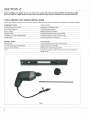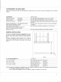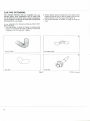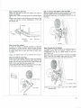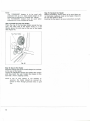
1
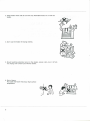
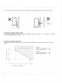
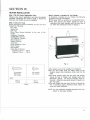
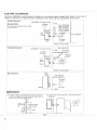
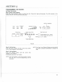
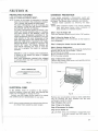
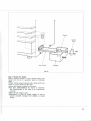
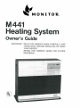
SAFETY ALERT SYMBOL
These symbols appear as important safety precautions and should be understood
and followed by the owner to assure safe operation of the heater.
For Quick Reference
Page
SECTION A: £±Important Caution
SECTION B: Specifications
Special Features
Safety Features
SECTION C: Tools Needed for Heater Installation
Accessories You May Need
Window Installation
Flue Pipe Extensions
SECTION D: Heater Installation
Flue Pipe Clearances
SECTION E: Fueling
Fueling Options Available
External Tank Installation
Empty Fuel Tank
SECTION F: Starting Instructions
SECTION G: Adjusting Room Temperature
SECTION H: Turning Off the Heater
SECTION I : Relighting the Heater
SECTION J : Programming the Heater
Setting the Clock
Programming for Automatic Heater Operation
Manual Operation
SECTION K: Protective Features
Loss of Power-Automatic Reset
Electrical Fuse
Overheat Prevention
SECTION L: Care of the Heater
SECTION M: Troubleshooting Guide
COPYRIGHT © MONITOR PRODUCTS, INC.,
•
-.
1
5
5
5
6
7
7
8
9
10
15
15
15
16
17
18
18
18
19
19
20
20
21
21
21
21
22
24
SECTION A
IMPORTANT CAUTION
AWARIMING
USE ONLY CRYSTAL CLEAR KEROSENE. NEVER
USE GASOLINE, WHITE GAS, CAMP FUEL OR
OTHER FLAMMABLE LIQUIDS. USE OF SUCH
FUELS CAN RESULT IN AN EXPLOSIVE FIRE AND
CAUSE SEVERE INJURY.
KEROSENE ONLY
GAS
ACAUTION
1. Make sure that there is no fuel leakage from fuel tank and fuel pipe joint.
2. Make sure that flue pipe (exhaust pipe, air supply hose) is connected
properly.
3. Keep heater clean and do not store any flammable items on or near the
heater.
4. Don't use the heater for drying clothes.
5. Should anything abnormal occur in the heater, remain calm, turn it off (do
not unplug) and contact your Monitor dealer.
6. Risk of burns.
Flue pipe and louver may have high surface
temperature.
7. Do not place yourself or others too close to the heater.
8. Installation of heater in extreme humidity or dust areas is not
recommended.
Any removal of unit parts or remodeling is strictly forbidden.
9. Do not sit on the heater.
Placing ornaments or plants on the heater is not recommended.
Excess heat may cause damage to ornament or plant and overwatering
or spilling of water may cause shock to you or damage to the
heater.
10. In areas of heavy snow accumulation, flue pipe may need to be installed higher to avoid being buried.
In open areas with strong wind, a wind break may be necessary to avoid exhaust gases being blown
back into the intake and causing poor combustion.
u_ 24"min
Long _^
Extension
kit
Must be higher.
Snow
11. Do not install nor exhaust the flue pipe into a crawl space or underneath floor nor into a flue or chimney.
X
-Flue
or
Chimney
12. OPERATING ALTITUDES HIGHER LIMITS
This heater is designed to be used no higher than 3000FT above sea level. Do not operate at altitudes
higher than 3000FT above sea level.
13.0PERATING TEMPERATURE LIMITS
Please use the Monitor within the range of temperatures indicated by the shaded area shown on the graph
below.
Operating Temperature Limits
Point A
Inside Area Temperature — 4°F
Outside Temperature
— 22°F
Point B
Inside Area Temperature 60°F
Outside Temperature
— 40°F
-10
0
20
Inside Area Temperature (°F)
40
60
SECTION B
SPECIFICATIONS
Model
Fuel Type
Heater Efficiency
Heat Rating
Heater Output
Fuel Tank
Fuel Consumption
Power Source
Power Consumption
Heated Air Delivery
Vent Pipe Hole
Dimensions
Weight
Monitor 441
Crystal Clear Kerosene
93%*
High: 43,000 BTU/hour
H.Medium: 33,900 BTU/hour
LMedium: 21,000 BTU/hour
Low: 16,200 BTU/hour
High: 40,000 BTU/hour
H.Medium: 31,500 BTU/hour
L Medium: 19,500 BTU/hour
Low: 15,OOP BTU/hour
Separate (Not supplied with heater)
High: 0.319 Gallon/hour
H.Medium: 0.25 Gallon/hour
L.Medium: 0.16 Gallon/hour
Low: 0.12 Gallon/hour
120 Volts AC; 60 Hz.
Ignition: 340 Watts
Operation: 80 Watts (Average)
High: 388 Cubic feet/minute
H.Medium: 388 Cubic feet/minute
L.Medium: 300 Cubic feet/minute
Low: 300 Cubic feet/minute
2/1>-inches Diameter
Height: 26.6 inches
Width: 28.7 inches
Depth: 13.8 inches
82 Pounds, empty
* When considering heat of condensation is lost, then net efficiency is 87%.
SPECIAL FEATURES
SAFETY FEATURES
AUTOMATIC IGNITION
MEMORY BACK UP: Set memory can be kept in case
of power failure for up to 5 minutes.
DUAL BLOWERS: Separate fans for combustion and
room air circulation.
THERMOSTATICALLY CONTROLLED: Adjusts to the
desired room temperature.
BUILT-IN TIMER:Heater will automatically operate as
programmed by the user.
AUTOMATIC RESET AFTER POWER FAILURE: Heater
will automatically resume operation after power
is restored.
INDICATOR LIGHTS: Easy-to-see signals show when
heater is in operation, when timer is activated, and
when the burner is operating in low, medium or
high modes.
CHOICE OF FUEL SUPPLY: Connect to separate tank.
MULTIPLE HEAT EXCHANGER:Extracts 87% of heat
from burner.
CLEAN OPERATION: Products of combustion are vented
outside.
CONSUMES NO ROOM AIR :Airfor combustion is drawn
from outside.
EASY INSTALLATION includes all parts required for
standard installation.
SAFE RE-LIGHTING:Heater will not restart until its
combustion chamber has cooled.
ELECTRICAL PROTECTION: Heater automatically shuts
off in the unlikely event of a malfunction in the
electrical circuitry or disruption of the power supply.
NO EXHAUST IN ROOM: Products of combustion are
discharged outdoors.
FLUE PIPE:Outside air is drawn through a pipe-withina-pipe venting system. This process preheats
combustion air and regains heat from exhaust
gases.
A CAUTION:ALTERNATE POWER SOURCES
The Monitor 441 may not operate when powered
by sources such as an auxiliary generator, UPS
(Uninterrupted'Power Source), inverters, etc. Check
with your dealer for guidance on specific
applications.
SECTION C
Before installing your heater, be sure to check and comply with local and state building and electrical codes
that may apply to vented heaters in your area. Permanent wiring must be installed by a licensed electrician.
TOOLS NEEDED FOR HEATER INSTALLATION
Check the following charts to be sure you have all the tools required to install your Monitor 441 Heating System.
STANDARD TOOLS
APPLICATION
Phillips Head Screwdriver
Steel Tape Measure
Pen or Pencil
Exterior Caulk
Yardstick or Long Straight Edge
Soapy Water
Installation of Heater Parts
Taking Measurements
Marking Drilling Location
Caulking Between Packing and Wall
Checking Angle of Hole for Flue Pipe
Lubricating Sleeve Hardware
SPECIAL TOOLS
APPLICATION
Electric Drill
inch Hole Saw Attachment
Long % inch Drill Bit
Level
Accommodating Hole Saw and Drill Bit
Cutting Hole for Flue Pipe
Drilling Pilot Hole Through Wall
Checking Angle of Hole for Flue Pipe and for checking
heater level.
Fig. 1
6
ACCESSORIES YOU MAY NEED
Check the list below and see your MPI dealer for accessories you may need or want for installation of your heating
system.
ACCESSORY
Medium Flue Pipe
Long Flue Pipe
Electric Lifter Pump
APPLICATION
For use where wall thickness is up to \41A inches
For use where wall thickness is up to 20 inches
For use with large capacity tank where gravity feed is not
practical
For use where "through-the window" flue pipe installation
is desired
For use where "standard" installation is not practical
P/N 8206
P/N 8005
P/N 1101
Window Installation Kit P/N 8208, 8209, 8001
(See Window Installation below)
Extra Short, Short, Medium or
Long Extension Kit or Elbow Adapter Kit
(See Flue Pipe Extensions, page 8)
Fitting and Tank
For large capacity fueling: To be dealer installed
WINDOW INSTALLATION
The use of "through-the-window" installation for your
flue pipe will require a window installation kit and one
of the 4 (extra short, short, medium or long) extension
kits.
In order to determine which extension kit is required,
measure the distance from the floor to the TOP of
your window sill (see Figure 2) and refer to the chart
below.
Fig. 2
IF THE MEASUREMENT IS:
20% to 25 inches
25 to 33% inches
33% to 511A inches
511A to86M inches
YOU NEED
Extra Short Extension Kit
Short Extension Kit
Medium Extension Kit
Long Extension Kit
Elbow Adapter Kit
P/N
P/N
P/N
P/N
P/N
8212
8204
8203
8202
8213
NOTE: Window kit installation is prohibited when the window is required to meet the local building code requirements
for ventilation, emergency escape, or rescue.
One or more Elbow Adapter Kit may be needed if heater is installed on inside wall.
FLUE PIPE EXTENSIONS
Four standard extension kits are available from your
Monitor dealer. Most installations can be made with
one of these kits. In special cases, custom installations
may be required. These may be made with components
purchased from your dealer.
2. These elbows should include the one used at the
heater but not the one on the air supply hose nor the
integral bends in the flue pipe. (See Figure 3)
3. The correct damper as shown on Page 13 must be
used.
In any installation the following limitations MUST NOT
BE EXCEEDED:
1. The total length of either the intake or exhaust pipe
should not exceed 10 feet with 3 elbows, 13 feet with
2 elbows, or 16 1/2 feet with 1 elbow.
Exhaust Elbow
Air Supply Hose
90' Joint
Flue Pipe
Rg. 3
8
Do not count
SECTION D
HEATER INSTALLATION
Step 1: Fill Out Owner Registration Card
Remove your owner registration card from the plastic
envelope containing the owner's guide. It should be
filled out and mailed as soon as possible.
Step 2: Check for Parts
Before discarding packing materials, be sure you have
located the following:
Flue Pipe
Sleeve Nut
Spill Tray
Room Temp. Sensor (attached to the rear of the
heater)
Cardboard Template
"STANDARD" Damper
"EXTENSION" Damper
Wall Clamps (2)
Rubber Packing
Joint Pipe
Cloth Insulation Cover
Outer Flange
Pipe Holder
Small Bag of Screws
Tapping, Type A —
Tapping, Type A —
Step 3: Choose a Location for Your Heater
In choosing a location for your heater, the following
guidelines must be considered:
• The heater MAY be installed on combustible floors.
• The area around the heater should be free of
obstacles that might interfere with the free flow of
air. Allow the clearances shown in Figure 5.
5'A
10"
Fig. 5
For securing
sleeve and
wall clamps
For securing
wall clamps
SIZE
Tapping
Tapping
Fig. 4
• The heater must not be installed in a fireplace.
• An AC wall outlet must be within reach of the
heater's power cord. Extension cords must not be
used.
• The area outside where the flue pipe will emerge
should be free of foliage, fuel storage tanks and
flammable objects. Air should circulate freely in
the area. Allow the clearances shown in Figure 6 on
the next page.
• The wall where flue pipe hole will be cut should be
free of plumbing pipes, electrical wires, studs, air
ducts and other obstacles.
NOTE:Use the cardboard template provided with your
heater for flue pipe location.
FLUE PIPE CLEARANCES
Flue pipe installations should provide for venting to an unconfined space through which there is a free flow of
outdoor air. Clearances to adjacent walls or obstacles must comply with the requirements shown below.
Frontal Clearance
Cnmhustible "|||m"
ACAUTION:
Do not attach anything onto the outlet
of the flue pipe.
m
t
4
2, t"
(60cm)
or more
5K' _U «—
(13.5cm)
BodyClamp
~s=r
Any construction f
above Flue Pipe
]
must not come _. \
within 24" (60cm)
of front obstacle
5%"
(14
cm)
-or 4
more
24" (60cm)
or more
£T (20cm)
or more
1
Ground or slab surface
\
Non-combustible
Combustible -•• m""|!i1 " "'|m
•4-
24" (£ iOct n)
or m ore
~
Wa
"
Combustible
liillliililiiiHiliiiii|i iiiiiiiiiiiiiiimiiitillllllllliiiilnnl
|f- _4_
5
_d 3.5cm)
/ J^
•dr
1
45° "^
•-^/
f
Body
Clam
Heate
>|
1 Front Obstacle
t
fa —
Heater
Overhead Clearance
-Wall
]
1
24' (60cm)
or more
T
12" (30cm)
or more
~ Flue Pipe
Ground or slab surface
Side Clearance
Body
Clamp
Side obstacle
—L\_I
18" (45cm)
or more
y fj=- -V .
Heater-
Flue Pipe
--*-
— Wall
IMPORTANT:
(1) In areas of heavy snow falls, ground surface clearance
must be increased according to average snow falls, to
prevent flue pipe from being buried.
Long
Extension
kit
(2) In open area with strong wind, a wind break may be
necessary.
i«- 24"min -H
"T
Must be higher.
Snow
Fig. 6
10
Use the template to position the hole to be drilled.
The "red dot" indicates the exact center of the hole.
Using an electric drill and a long drill bit, make a
pilot hole through the wall (Figure 7). Be sure the hole
extends through the outside wall.
Step 4: Drill a Pilot Hole
NOTE: The following directions apply to "standard"
installation. For other methods, follow instructions
included with accessory kits.
For walls up to 8% inches thick, use a short
flue pipe; for walls up to 141/2 inches thick, use
a medium flue pipe; and for walls up to 20 inches
thick, use a long flue pipe.
Position of hole
Template
Fig. 7
CAUTION: The opening on the inside wall should be approximately % inch higher than on the outside wall so
the flue pipe will slope downward when installed. This will allow condensation to drain outdoors.
Step 5: Cut the Hole for the Flue pipe
Using a hole saw attachment and an electric drill, cut
a 2l/z inch diameter hole through the inner and outer
walls (Figure 8).
After the hole is cut, use a straight edge and a level
to be sure the inside opening is approximately % inch
higher than the outside opening.
NOTE: After cutting the inside wall, remove the insulation.
Make sure there are no obstructions inside the
wall, such as electrical wiring, water pipes, hot
air ducts, etc.
Wall
Fig. 8
11
with the 3 # SxKtapping screws(Figure 9). (See Figure
4 for screw size and application.)
Step 6: Install the Flue Pipe
From INSIDE the building, insert the flue pipe (with
arrow pointing "up") into the hole. Fasten the flue pipe
NOTE: Top center port is an extra exhaust port.
tapping screw
Fig. 9
Step 7: Install the Outer Flange
Apply caulking material to the inside ridge of the
rubber packing (Figure 10).
Holding the "Up" mark to the top, slide the rubber
packing onto the sleeve (caulk side to the wall).
NOTE: If it is difficult to slide the packing onto the
sleeve, apply soapy water to the inside of the
packing.
Once the rubber packing is in place, slide the outer
flange onto the sleeve with the conical side pointing
outward (Figure 11).
Screw the flue pipe nut onto the flue pipe grooves,
and tighten it firmly (Figure 11).
Rubber Packing
Flue Pipe Nut.
Outer Flange
Fig. 11
12
Fig. 10
Step 8: Install the Spill Tray
Place the spill tray on the floor where you plan to
locate your neater.
Remove the 2 sets of screws from the cabinet (Figure
12).
Position the heater on the spill tray so the legs of the
cabinet fit into the circular indentations in the spill
tray (Figure 12).
Step 11: Connect the Heater to the Flue Pipe
Move the heater toward the wall, guiding the joint pipe
into the center port of the flue pipe (Figure 14).
Be sure the joint pipe is completely inserted into the
flue pipe.
Screws
Retainers
Fig. 12
Legs
Spill Tray
Step 9: Level the cabinet
In order for heater to operate properly. It must be
positioned on a level surface. Ensure proper leveling
by adjusting each leg and by using a carpenters level
to check both side to side, and front to back level
condition.
Attach and tighten both sets of retainers and screws.
Step 10: Install the Joint Pipe
At the rear of the heater, slide the large end opening
of the joint pipe into the exhaust port outlet of the
heater. Be sure the joint pipe is fully seated. Slide the
fabric cover over the joint pipe (Figure 13).
The o-rings that seal the joint pipe may be dry and tight.
A little soapy water will ease installation.
Step 12: Install the Air Damper
If installation is standard (that is no extension kits are
required), place the air damper marked with a
"STANDARD" over the air intake flange on the flue
pipe (Figure 15).
Place the hose band around the end of the air supply
hose. Push the air supply hose onto the air intake
flange and secure the hose with the hose band.
Fabric Cover
Joint Pipe
NOTE:Do not place intake hose onto metal capped
exhaust port.
Fig. 13
13
NOTE:
The "STANDARD" damper is to be used with
extension kits up to a total overall length of 20
inches and a maximum of 3 bends (90° elbow).
The "EXTENSION" damper must be used when
extension kit or kits exceed 20 inches.
Step 13: Install the Flue Pipe Holder
Place the ring of the flue pipe holder around the flue
pipe. The other side of the holder hooks in a slot
directly above the joint pipe at the rear of the heater
(See Figure 16).
Flue Pipe Holder
Fig. 16
Step 14: Secure the Heater
Insert the narrow ends of the 2 wall clamps into sockets
on the rear of the heater.
Loosen the adjustment screws and extend the clamps
until they touch the wall. Fasten the clamps to the
wall with 2 #8x% tapping screws.
NOTE: If use of wall clamps is not feasible or
practical, the heater should be secured by
screws to floor through punched holes in spill
tray.
14
Step 15: Recheck the Heater
Before proceeding, check again to be sure there are
no flammable materials close to the heater. Check to
be sure the heater is level.
Examine the flue pipe to be sure connections are tight.
SECTION E
FUELING
WARNING: Use only crystal clear kerosene. Never use gasoline, white gas, camp fuel or other flammable
liquids. Use of such Fuels can result in an explosive fire and cause severe injury.
FUELING OPTIONS AVAILABLE
EXTERNAL TANK INSTALLATION- Gravity Fed
Fueling of your Monitor 441 Heating System can be
accomplished in one of 2 ways:
NOTE:External tank installations must comply with the
National Fire Protection Association code NFPA
31 or locally applicable codes, such as the 1979
Uniform Mechanical Code No. 5-1, that are
consistent with NFPA 31. Check with your local
building official.
1. Gravity Fed Large Capacity External Tank:
Practical for large heating needs where bulk delivery
of kerosene is available. This system should be
installed by a qualified plumber or fuel supply
technician.
2. Large Capacity External Tank with Pump:
For large heating needs where a gravity fed system
is not practical. An electric lifter pump, especially
designed for use with your Monitor 441 heating
system, is available from your dealer.
When using a gravity fed tank or pumping system to
supply fuel, the inlet pressure to the heater must not
exceed 2.5 psi.
To install a large capacity, gravity fed external tank,
follow the instructions below, and refer to Figure 17 for
one possible installation. Use of a qualified installer is
recommended.
• Installation height of the bottom of the fuel tank
should be 16 inches or more above the floor surface
on which the heater stands. This ensures that inlet
fuel pressure will be sufficient.
• The top of the fuel tank should be no higher than
Ql/z feet above the floor under the heater. Heights
above 81A feet will exceed the 2.5 psi inlet limit,
and a pressure reducer will need to be installed at
or near the unit.
• The horizontal length of piping should not exceed
100 feet and should be free of sharp bends or
obstructions.
• Piping should include no inverse U-type bends (to
avoid air locks, which could block the fuel supply).
• Only % inch OD copper tubing should be used. The
tubing should be bent carefully to avoid crimping.
• A fuel filter is recommended for use on the fuel line
near the tank, and a shut-off valve should be
installed at the tank.
• A flare adaptor can be used to make a flared tubing
connection between the unit and the filter at the
tank.
• The fuel tank should be located no closer than 3
feet to a source of heat.
• The fuel tank should have an opening for filling on
the top and vent with a weather-proof cap on the
side. On some tanks the vent and fill spout use the
same opening.
When using a gravity fed tank to supply fuel, the inlet
pressure to the heater must not exceed 2.5 psi.
The Monitor 441 comes equipped with a %" pipe
thread connection. A straight, or 90 degree pipe-toflare fitting or a firomatic valve can be used for the
fuel line connection. If a firomatic valve is being used:
Valve Position-Open/Close
Turn counterclockwise to open, clockwise to close. If
threaded valve stem is sticking up about ^", valve is
open. If handle screws off stem, valve is closed.
15
Outdoor Fuel Tank
Shut-off Valve
maximum
(2.6m)
16"
t-%" Threaded Connection
I1
.
\
OD Copper Tubing
NOTE: Fuel tank must be a minimum 3 feet away
from flue pipe.
(QA
"^
\
—
—->
^ '
—"
r_
3
1
Fig. 17
EMPTY FUEL TANK
If at any time during the operation of your heater you
find.
• Burner Status indicators are blinking.
• No heat.
• No flame.
You can assume you are out of fuel.
Should this situation occur, take the following steps.
16
Step 1: Turn the Heater Off
Press the Operation Button to put it in the "Off"
position.
Step 2: Refuel
Refill your fuel tank with kerosene.
Step 3: Turn the Heater On
Press the Operation Button to put it in the "On"
position.
SECTION F
STARTING INSTRUCTIONS
Step 1: Plug in the Heater
Plug in the AC cord, and route it away from the area
of the flue pipe. It is recommended that no other
appliance share the same outlet.
Step 2: Prime the Heater
If using the heater for the first time, or if the heater
has not been in operation for sometime, press the fuel
set lever at the lower right hand side of the cabinet
and release it slowly 2 or 3 times (Figure 18).
Fuel Set Lever
/!\ CAUTION: Do not continue pressing lever repeatedly as this may cause overfilling of constant
level valve inside.
NOTE:After a power outage, there is a three-minute
waiting period before the unit restarts, provided
the ON/OFF switch is in the "ON" position.
Fig. 18
Step 3: Set "ON" Button
Depress the operation button to put it in the "ON"
position. The "Operation Lamp" lights indicating "Set
Room Temperature" and "present roomi temperature".
Burner status lamps will light and ignition will start
after approximately three minutes. In 5 to 10 minutes
the circulation fan will start to operate, and warm air
will be felt coming through the cabinet grill.
RUN
AUTO
ECONOMY
PLUS
BURNER STATUS
OPERATION
ON/OFF
TIMER SELECTOR
CLOCK
AUTO ECONOMY SFT 1st 2nd 3rd 4th
PLUS
CD
ROOM
i- n - c Q
/ i_i - /_/ o
TIME/TEMP SET
— -_. Jill iii _ TIME!
i—i
SET
TEMP
AM
PM
TEMP [
I HOUR MINUTE SET CLEAR
|
CD CD CD CD
UP DOWN
Fig. 19
17
SECTION G
ADJUSTING ROOM TEMPERATURE
Pressing either the "Up" or "Down" button will increase
or decrease the set temperature by 2 degree increments.
Once desired temperature is displayed, press set
button to lock into memory.
The lights on the control panel will indicate the level
of heater operation — low, medium or high. The heater
will automatically change its heat output until the
desired room temperature is reached. While it cycles,
you may hear the circulation fan change speed.
Depending on the output required to maintain the
desired room temperature, the indicator lights will
illuminate in the following pattern:
BURNER MODE
LIGHT PATTERN
High
H.Medium
L Medium
Low
Off
8 indicators — On
6 indicators — On
4 indicators — On
2 indicators — On
*No lights on
« The heater will shut itself off temporarily when the desired room temperature has been reached and restart automatically when
necessary to maintain room temperature.
NOTE: The heater may display room temperature 4 degrees above set temperature, depending on heater load
conditions, before shutting itself off.
INSTRUCTIONS FOR ECONOMY PLUS MODE
To engage the economy plus mode, simply press down the button labeled "Economy Plus", to disengage press
again.
NOTE:Operation switch must be "ON" and in manual mode.
This feature minimizes the "ON" and "OFF" cycling of the unit by allowing it to overshoot the set temperature by
12 degrees instead of the normal 4 degrees.
The advantages of this feature are to increase the overall efficiency of the unit by:
1. Decreasing electrical consumption by decreasing the frequency of ignition cycles.
2. Reducing heat loss during the prepurge and postpurge cycles.
3. Reducing inefficient combustion associated with start up and shut down.
4. Prolonging component life by decreasing expansion and contraction of internal parts.
NOTE: This feature could be compared to driving an automobile in stop and go traffic (regular mode) versus
highway driving with cruise control engaged (Economy Plus mode).
SECTION H
SECTION I
TURNING OFF THE HEATER
REUGHTING THE HEATER
To turn off the heater, press the Operation Button to
put it in the "Off" position (Figure 19). The operation
light will go out, and the fuel flow will stop.
After turning heater off the fans will continue to run
until unit has cooled down to the point where the
fans will automatically stop.
Automatic controls prevent your heater from relighting
after the Operation Button has been set to "Off" until
heater has cooled.
If the Operation Button is put in the "On" position
during the cooling period, the heater will automatically
relight at the end of the period.
18
SECTION J
PROGRAMMING THE HEATER
SETTING THE CLOCK
Step 1: Set the Timer Selector
Press the "Timer Selector" button, at which time the "Clock Set" Light will illuminate. The LED indicator in the
Display Window will show 88:88 at this point.
DISPLAY WINDOW
RUN
AUTO
EC
£LN°SMY
OPERATION
ON/OFF
AUTO
ECONOMY
PLUS
CD
SET
BURNER STATUS
TEMP
AM
PM
ROOM
Q
n
TIME/TEMP SET
TIMER SELECTOR
CLOCK
SET 1st
2nd 3rd 4th
mSi mmm m—m mmm mmm
HOUR MINUTE SET CLEAR
TEMP |
|
CD CD CD
UP DOWN
CD
TIMER SELECTOR
Fig. 20
Step 2: Set the Hour
Press the "Hour" Button until the correct hour (either
A.M. or RM.) appears in the window.
NOTE: The "Hour" and "Minute" Buttons can be pressed
and held or pressed momentarily to change the
time.
Step 3: Set the Minute
Press the "Minute" Button until the correct time
appears in the window.
Immediately press the "Set" Burton.
NOTE: If the "Set" Button is not pressed within 1 minute
after the time is set, the programming will be
cancelled.
19
PROGRAMMING FOR AUTOMATIC HEATER OPERATION
The Monitor 441 Heating System is capable of providing
up to 4 different temperature settings for 4 different
times of the day. Not all 4 settings have to be used;2,
3 or 4 settings can be used. A clear understanding
of programming temperatures and time from the previous
pages is needed before programming the automatic
settings. Also, the present time must have been set.
Step 3: Activate Automatic Operation
For the heater to operate on automatic once the
settings are in memory, simply press the "Auto" Button
on the control panel. The "Auto" Light will illuminate to
confirm the heater is in the automatic operation mode.
The heater will now maintain the programmed temp
for that time of day.
Step 1: Setting the 1st Time/Temperature
Pressing the Timer Selector Button will illuminate the
Time/Temp Light.
Press the "Time" Button. Set the 1st desired time by
pressing the "Hour" and "Minute" Buttons as described
under, "Setting the Clock". Once the desired time "AM
or PM" is displayed, press the "Set" Button to lock
into memory.
Press the "Temp" button. Set the desired temperature
for the 1st time setting by using the "Up" and "Down"
Buttons. Once the desired temp is displayed, press the
"Set" Button to lock into memory.
IMPORTANT:The heater will not operate in automatic
unless the On/Off switch is in the "On"
position.
Example: 1st Time/Temp
SAM 60°
Step 2: Setting the 2nd Time/Temperature
Press the Timer Selector Button again and the 2nd
Time/Temp Light will illuminate.
Follow same steps as above, except for 2nd time/temp.
(ie;2nd 5PM 74Degrees)
Repeat if a 3rd or 4th setting is desired.
Typical Example of a 4-time/temp selection:
TIME
TEMP
1st
SAM
60°
2nd
5PM
74°
3rd
11PM
70°
4th
5:30AM
76°
20
Step 4: Clearing An Automatic Setting
If you wish to clear any automatic setting, press the
Timer Selector Button to the approprate setting and
press the "Clear" button. A new setting will need to be
entered otherwise the old setting will return after 30
seconds.
MANUAL OPERATION
To deactivate the automatic operation, simply press
the "Auto" Button. The "Auto" Light will no longer be
illuminated and the heater will run on a manual setting.
This setting will be determined by the previous auto
setting for that time of day, unless reset. The automatic
settings will remain in memory even if the unit is
running in manual, unless there is a power outage for
more than 5 minutes.
SECTION K
PROTECTIVE FEATURES
OVERHEAT PREVENTION
LOSS OF POWER-AUTOMATIC RESET:
If your heater overheats, a thermostatic switch will
automatically stop the flow of kerosene and extinguish
the flame. The Burner status indicators are blinking.
Restore heater operation by following the steps
below.
NOTE: Other symptoms listed in the trouble shooting
chart may cause burner status indicators to
blink, besides an overheat situation.
NOTE:If power to the heater is interrupted, a thud-like
noise may be heard in the combustion chamber.
This is nomal, and should not cause alarm.
For power interruptions of up to 5 minutes, the
set memory is kept and will resume operation
automatically with the set memory.
For power interruptions beyond 5 minutes, your
heater will resume operation (after a 3 minutes
cool down period) in the MANUAL mode and
maintain room temperature according to the
setting temperature you've selected by using the
slide selector for the reset temperature at the
lower right hand side of the cabinet (Figure 21).
When the TIME Button is pressed or the TIMER
SELECTOR Button is pressed to illuminate the
CLOCK SET Light, The Display Window will
show 88:88 indicating the need to reset the
clock and re-program the heater for automatic
operation.
REMARK:In order to display reset temperature,
it should be set before the heater is plugged
in and energized.
New reset temperature selected after plugged
in will take effect only after a power loss, greater
than five minutes.
Step 1: Turn the Heater Off
Press the Operation Button to put it in the "Off" position.
Step 2: Allow the Heater to Cool
Wait approximately 30 to 45 minutes for the heater to
cool completely.
Step 3: Unplug the Heater from the Wall Outlet.
Step 4: Remove Obstructions
The overheated condition may be caused by obstructions
blocking the air flow to the heater. Check:
• The front of the heater
• The circulation fan (on the back of the heater).
• The flue pipe (outside)
Step 5: Remove the Louver
Remove the screws at the louver, and carefully remove
the louver (Figure 22).
RESET TEMPERATURE
50 52 54 56 58 60 62 64 66 68 70 72 74 76 78 80
Louver
Fig. 21
ELECTRICAL FUSE
In the unlikely event of a failure in the heater's
electrical system, a fuse will "blow" and interrupt the
power. Do not attempt to change the fuse.
Contact your MPI dealer for the name of a trained
and certified service representative in your area.
NOTE: Using a surge protector can minimize the chances
of a blown fuse caused by power surges.
Fig. 22
Remove any accumulation of dust or other matter that
may be covering the burn chamber and the heat
exchangers inside the heater.
Step 6: Replace the Louver
Step 7: Plug in the Heater
Step 8: Re-program the Heater
Step 9: Turn Heater On
/\ CAUTION: If the unit overheats a second time, turn
it off and contact your MPI dealer for
service.
21
SECTION L
CARE OF THE HEATER
Push operation switch to "OFF" remove the AC Plug from the wall outlet and wait approximately 30 minutes for
the heater to cool before performing any of the following steps.
Step 1: Retrieving Objects from Inside the Heater
Should an object fall inside the heater, through the
grill openings, it must be removed to avoid affecting
the operation of the heater.
After allowing the heater to cool, remove the front
cover panel. (See Step 5 of the previous section.)
After the object has been removed, replace the front
cover before attempting to re-start the heater.
Step 2: Cleaning the Cabinet
When the cabinet is soiled, wipe it with a damp cloth.
Restore the shine with a dry cloth.
The use of abrasive household cleaners may dull
the finish.
Step 3: Checking the Flue Pipe
At the beginning of each heating season, check the
inside of the flue pipe. Foreign matter, spider webs,
etc. must be removed.
Be sure all fittings and joints are tight.
Step 4-Cleaning the Interior
Remove the Front Cover Panel (as described in Step
5 of the previous section), and vacuum and wipe away
dust or other accumulation.
Look for signs of fuel leakage around the joint pipe
and the bottom of the cabinet. If fuel is detected, wipe
it away and if necessary, contact your MPI dealer for
any necessary repairs.
Step 5: Cleaning the Blower Guard
Heating efficiency will be reduced if the blower guard
at rear of the cabinet is blocked with dirt or dust.
Blockage also produces a rise in heat that could cause
the heater to shut off.
Wipe the guard clean at least once a week.
22
Step 6: Cleaning the Fuel Strainer
The strainer of the fuel constant level valve should be
cleaned once a year and before storing heater at the
end of each season.
Step 6-A:
Turn knob of the shut-off valve installed at the external
tank to close the fuel line.(See Figure 17).
Step 6-B:
To catch the fuel which will drain out, set the drain
guide made by cardboard below the strainer cover,
with a small container under it. (See Figure 23)
Step 6-C:
Loosen the two screws from the strainer cover and
remove.
Step 6-D:
Remove the strainer and wash with pure kerosene.
If strainer is damaged, replace it
Step 6-E:
Return the strainer to its original position.
strainer cover and screw to secure.
Replace
Step 6-F:
Wipe away any spilled kerosene.
Step6-G:
Turn the knob of the shut-off valve to open. Check for
kerosene leakage.
NOTE: Your Monitor may sometimes require more
service than that shown above. Should this occur
please contact your Monitor Products, Inc., dealer
for service. A preseason maintenance check up
could be performed by your dealer to ensure
trouble free operation during the season. Ask
him for details of his routine maintenance
program.
Strainer
Cover
Drain Guide
Container
Fig. 23
Step 7: Storing the Heater
During summer months or long periods when your
heater will not be in operation, take the following
steps:
• Clean off the exterior cabinet with a damp cloth, and
brush or vacuum dust from the grills.
• Cover the heater to protect it from dust.
• DO NOT DISASSEMBLE the heater or extension
kits. Replacement of lost parts is an unnecessary
expense.
• Shut off fuel supply to unit.
• Disconnect or shut off power supply to unit to
prevent possible damage from lighting or power
surges.
23
SECTION M
TROUBLESHOOTING GUIDE
Should symptoms appear during the operation of your heater, refer to the chart below, If you are unable to restore
normal operation, contact your MPI dealer for service.
SYMPTOM
Heater does not go on
with operation switch.
Heater extinguishes after
lighting.
CAUSE
Timer is in Auto.
REMEDY
Press Auto Button again.
AC cord is disconnected
from wall outlet. Power
failure.
Check plug and power source.
Reset circuit breaker.
Out of fuel.
Press the fuel set lever at the lower
right hand side of the cabinet.
Igniter Failure.
Call your MPI Dealer for Inspection
and/or Replacement.
Water in fuel.
Refill with fresh kerosene. Section L.
Note: If strainer is severely clogged,
contact your Monitor dealer to check
and clean the inside of constant level
valve and pump screen.
Clogged fuel strainer.
Clean fuel strainer.
See "Care of the heater"
Section L.
Press fuel set lever on lower right hand
side of the cabinet and release slowly
2 or 3 times.
Air pocket in fuel line.
Out of fuel.
See "Empty Fuel Tank" Section E.
Erratic changes in room
temperature. (Slight
differences in room
temperature are normal.)
Poor location of heat sensor.
Poor air movement.
Relocate the sensor.
Make sure clearances are kept around
unit.
Add room fans to better circulate air
throughout area.
Automatic timer does not
start heater.
Operation switch is not
in the "ON" position.
Depress operation button to "ON"
position.
Timer is in Manual.
Press Auto Button.
Timer improperly
programmed.
See "Programming for Automatic
Opearation" Section J.
Power interruption.
See "Loss of Power", Section K.
Flame does not reach
normal size.
Heater is not level.
Check level.
Poor flame, sounds of
combustion, soot at the
rear of the heater.
Loose flue pipe.
Allow heater to cool completely;
tighten all connections.
Soot on inside of burner
window or exhaust ports
of flue pipe.
Obstruction of combustion
air intake system or
combustion fan failure.
Inspect air intake system and air
supply elbow for blockage. Clean with
a brush.if necessary, and carefully
reconnect.
Heater switches from
Power interruption; automatic reset.
automatic to manual operation:
display window shows 88 - 88.
See "Loss of Power",
Section K.
NOTE:Several of the symptoms mentioned above may also be signs that your unit is due for routine maintenance,
especially if it is several years old. Contact your Monitor dealer for an appointment.
24
i-Monitor 441™ \fented Heating Systems Limited Warranty-,
MONITOR PRODUCTS, INC., warrants each
MONITOR 441 vented heating system sold by it to
be free from defects in material and workmanship,
under normal use and service, for one year after
the date of original retail purchase, subject to the
term and conditions stated below. An extended
parts only warranty period of 36 months is provided
for combustion chamber and heat exchanger. The
remainder of the unit is subject to the 12 months
warranty as provided herein.
1. WARRANTOR :This warranty is granted by
MONITOR PRODUCTS, INC., P.O. Box 3408,
Princeton, New Jersey 08543.
2. PARTIES TO WHOM WARRANTY IS EXTENDED:
This warranty shall be extended only to the
original retail purchaser.
3. PARTS COVERED: All
products
and parts
manufactured by or for MONITOR PRODUCTS,
INC., except as provided for herein. Replacement
parts are warranted only for the balance of the
original warranty period.
4. PARTS NOT COVERED: The following parts are
not covered by this warranty: fuel filters, venting
kits, extension kits, fuses, and all parts damaged
by lightning.
5. REMEDY: If, within the applicable warranty
period, any product or part included in this
warranty proves to be defective in material and/or
workmanship, then MONITOR PRODUCTS, INC.,
shall repair or replace, at its option, the defective
product or part. Service at the point of installation
(not including dealer travel time) will be provided
at no charge to the customer, but must be
performed by a MONITOR PRODUCTS, INC.,
dealer authorized to sell and service the
MONITOR 441 vented heating system.
6. PROCEDURE FOR OBTAINING PERFORMANCE
UNDER THIS WARRANTY: In order to obtain
performance of the obligations under this
warranty, the original purchaser must promptly
(in no event later than thirty (30) days after
discovery of the defect) notify the local MONITOR
PRODUCTS, INC., dealer authorized to sell and
service the MONITOR 441 vented heating system.
Service will be provided during normal business
hours within a reasonable time after the dealer
has been notified of the need for service. If you
are unable to locate a local MONITOR
PRODUCTS, INC., dealer authorized to sell and
service the MONITOR 441 vented heating system,
call or write to: SERVICE DEPARTMENT,
MONITOR PRODUCTS, INC., P.O. BOX 3408,
PRINCETION, NEW JERSEY 08543, 908-3290900.
Any claim made under this warranty must be
accompanied by proof of original purchase date
sales invoice or cancelled check showing
serial number is satisfactory evidence.
PART NO.1153
7. SOLE REMEDY: The remedy and liability for any
breach of warranty, express or implied, set forth
above is the sole and exclusive remedy and the
limit of liability for any such breach.
8.
EXCLUSIONS AND IMPLIED WARRANTIES: THIS
WARRANTY DOES NOT EXTEND TO ANY
DEFECT DUE TO THE NEGLIGENCE OF
OTHERS, FAILURE TO INSTALL, OPERATE OR
MAINTAIN THE HEATER IN ACCORDANCE
WITH THE INSTALLATION, OPERATION AND
MAINTENANCE INSTRUCTIONS FURNISHED
WITH EACH NEW HEATER, UNREASONABLE
USE, ACCIDENTS, ACTS OF GOD, FIRE, SNOW,
FLOODS,LIGHTNING,ALTERATIONS,ORDINARY
WEAR AND TEAR, THE USE OF UNAUTHORIZED
OR
NON-STANDARDIZED
PARTS
OR
ACCESSORIES OR THE USE OF ANY FUEL
OTHER THAN GOOD QUALITY KEROSENE
SUCH
AS
1K GRADE. ALL
IMPLIED
WARRANTIES, IF ANY, ARISING UNDER
STATE LAW IN CONNECTION WITH THE SALES
BY MONITOR PRODUCTS, INC., OF ANY NEW
HEATER ARE LIMITED IN DURATION TO THE
DURATION OF THIS WRITTEN WARRANTY.
THERE ARE NO WARRANTIES, EXPRESS OR
IMPLIED, OF MERCHANTABILITY, FITNESS
FOR A PARTICULAR PURPOSE OR OTHERWISE
WHICH EXTEND BEYOND THIS WARRANTY
MONITOR PRODUCTS, INC., SHALL NOT BE
RESPONSIBLE FOR ANY INCIDENTAL OR
CONSEQUENTIAL DAMAGES. WHETHER AS A
RESULT OF BREACH OF WARRANTY,
NEGLIGENCE, STRICT LIABILITY IN TORT OR
OTHERWISE.
NOTE:SOME STATES
DO NOT ALLOW:(A)
LIMITATIONS ON HOW LONG AN IMPLIED
WARRANTY LASTS;OR (B) THE EXCLUSION
OR LIMITATION
OF INCIDENTAL
OR
CONSEQUENTIAL
DAMAGES,
SO THE
ABOVE LIMITATIONS OR EXCLUSIONS MAY
NOT APPLY TO YOU.
9. NO VARIATION OF TERMS: THE PARTIES
INTEND THAT THIS WARRANTY BE THE
EXCLUSIVE AND FINAL EXPRESSION OF
AGREEMENT. ..
No person has the authority to orally, in writing
or in any other way vary the terms, conditions
or exclusions, of this warranty or to make any
express warranties other than those contained
herein.
10. LEGAL RIGHTS: This warranty gives you specific
legal rights and you may also have other rights
which vary from state to state.
MONITOR PRODUCTS, INC.
P.O. BOX 3408
PRINCETON, N.J. 08543
COPYRIGHT © 1994 MONITOR PRODUCTS, INC.,