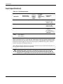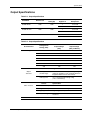
1
HP Uninterruptible Power System
R1500 XR Models
User Guide
August 2002 (Second Edition)
Part Number 217823-002
Hewlett-Packard Company shall not be liable for technical or editorial errors or omissions contained herein. The
information in this document is provided “as is” without warranty of any kind and is subject to change without
notice. The warranties for HP products are set forth in the express limited warranty statements accompanying such
products. Nothing herein should be construed as constituting an additional warranty.
HP Uninterruptible Power System R1500 XR Models User Guide
August 2002 (Second Edition)
Part Number 217823-002
Contents
About This Guide
Audience Assumptions ............................................................................................................................... vii
Important Safety Information ..................................................................................................................... vii
Symbols on Equipment............................................................................................................................... vii
Rack Stability............................................................................................................................................. viii
Symbols in Text......................................................................................................................................... viii
Related Documents.................................................................................................................................... viii
Getting Help................................................................................................................................................. ix
Technical Support ................................................................................................................................. ix
HP Website............................................................................................................................................ ix
Authorized Reseller............................................................................................................................... ix
Reader’s Comments..................................................................................................................................... ix
Chapter 1
Overview
Standard UPS Features .............................................................................................................................. 1-1
Communications Port.......................................................................................................................... 1-1
Network Transient Protector ............................................................................................................... 1-2
Overcurrent Protection ........................................................................................................................ 1-2
UPS R1500 XR Models............................................................................................................................. 1-2
Front Panel .......................................................................................................................................... 1-3
Rear Panels.......................................................................................................................................... 1-4
Power Management Software.................................................................................................................... 1-7
UPS Hardware Options.............................................................................................................................. 1-7
Remote Emergency Power Off Port .......................................................................................................... 1-8
Warranties.................................................................................................................................................. 1-8
$25,000 Computer Load Protection Guarantee................................................................................... 1-8
Pre-Failure Battery Warranty .............................................................................................................. 1-9
Chapter 2
Operation
Front Panel Controls and LED Indicators.................................................................................................. 2-1
Modes of Operation ................................................................................................................................... 2-2
Charging the Batteries ............................................................................................................................... 2-3
Placing the UPS in Operate Mode ............................................................................................................. 2-3
Returning to Standby Mode....................................................................................................................... 2-4
Initiating a Self-Test .................................................................................................................................. 2-5
HP Uninterruptible Power System R1500 XR Models User Guide
iii
Contents
Audible Alarms ......................................................................................................................................... 2-6
Silencing an Audible Alarm ............................................................................................................... 2-6
Shutting Down the System........................................................................................................................ 2-6
Chapter 3
Configuration
Placing the UPS in Configure Mode ......................................................................................................... 3-1
Configuration Parameters.......................................................................................................................... 3-2
Changing Configuration Parameters................................................................................................... 3-3
Chapter 4
Battery Maintenance
Precautions ................................................................................................................................................ 4-1
Charging Batteries..................................................................................................................................... 4-1
Determining When to Replace Batteries ................................................................................................... 4-2
Obtaining New Batteries ........................................................................................................................... 4-2
Replacing Batteries ................................................................................................................................... 4-3
Preparing the UPS............................................................................................................................... 4-3
Removing the Battery Pack ................................................................................................................ 4-3
Installing a New Battery Pack ............................................................................................................ 4-6
Testing the New Battery Pack ............................................................................................................ 4-6
Disposing of Used Batteries ............................................................................................................... 4-6
Care and Storage of Batteries.................................................................................................................... 4-7
Pre-Failure Battery Warranty.............................................................................................................. 4-7
Chapter 5
Troubleshooting
Troubleshooting ........................................................................................................................................ 5-1
Repairing the UPS..................................................................................................................................... 5-4
Appendix A
Regulatory Compliance Notices
Regulatory Compliance Identification Numbers.......................................................................................A-1
Federal Communications Commission Notice..........................................................................................A-1
Class A Equipment .............................................................................................................................A-1
Class B Equipment .............................................................................................................................A-2
Declaration of Conformity for Products Marked with the FCC Logo, United States Only................A-2
Modifications......................................................................................................................................A-2
Cables .................................................................................................................................................A-3
Canadian Notice (Avis Canadien).............................................................................................................A-3
Class A Equipment .............................................................................................................................A-3
Class B Equipment .............................................................................................................................A-3
European Union Notice.............................................................................................................................A-3
Japanese Notice .........................................................................................................................................A-4
China Taiwan Notice .................................................................................................................................A-4
Battery Replacement Notice......................................................................................................................A-5
iv
HP Uninterruptible Power System R1500 XR Models User Guide
Contents
Appendix B
Electrostatic Discharge
Grounding Methods .................................................................................................................................. B-1
Appendix C
Specifications
Physical Specifications ............................................................................................................................. C-1
Input Specifications .................................................................................................................................. C-2
Output Specifications................................................................................................................................ C-3
Battery Specifications ............................................................................................................................... C-4
Environmental Specifications ................................................................................................................... C-4
Index
HP Uninterruptible Power System R1500 XR Models User Guide
v
About This Guide
This guide provides step-by-step instructions for configuration, and reference information for
operation, battery maintenance, and troubleshooting for the Uninterruptible Power
System (UPS).
Audience Assumptions
This guide is intended for individuals requiring information about the use of HP UPSs. HP
assumes you are qualified in the servicing of computer equipment and trained in recognizing
hazards in products with hazardous energy levels.
Important Safety Information
Before installing this product, read the Important Safety Information document included with
the UPS.
Symbols on Equipment
The following symbols may be placed on equipment to indicate the presence of potentially
hazardous conditions:
WARNING: This symbol, in conjunction with any of the following symbols, indicates
the presence of a potential hazard. The potential for injury exists if warnings are not
observed. Consult your documentation for specific details.
This symbol indicates the presence of hazardous energy circuits or electric shock
hazards. Refer all servicing to qualified personnel.
WARNING: To reduce the risk of injury from electric shock hazards, do not open this
enclosure. Refer all maintenance, upgrades, and servicing to qualified personnel.
This symbol indicates that the component exceeds the recommended weight for
one individual to handle safely.
Weight in kg WARNING: To reduce the risk of personal injury or damage to the equipment,
observe local occupational health and safety requirements and guidelines for
Weight in lb
manual material handling.
HP Uninterruptible Power System R1500 XR Models User Guide
vii
About This Guide
Rack Stability
WARNING: To reduce the risk of personal injury or damage to the equipment, be sure
that:
•
The leveling feet are extended to the floor.
•
The full weight of the rack rests on the leveling jacks.
•
The stabilizing feet are attached to the rack in single-rack installations.
•
The racks are coupled together in multiple-rack installations.
•
Only one component is extended at a time. A rack may become unstable if more
than one component is extended for any reason.
Symbols in Text
These symbols may be found in the text of this guide. They have the following meanings.
WARNING: Text set off in this manner indicates that failure to follow directions in the
warning could result in bodily harm or loss of life.
CAUTION: Text set off in this manner indicates that failure to follow directions could result in
damage to equipment or loss of information.
IMPORTANT: Text set off in this manner presents essential information to explain a concept or
complete a task.
NOTE: Text set off in this manner presents additional information to emphasize or supplement
important points of the main text.
Related Documents
For additional information on the topics covered in this guide, refer to the following
documents:
•
HP Uninterruptible Power System R1500 XR Models Installation Instructions
•
HP UPS R1500 XR Models Extended Runtime Module Installation Instructions
•
HP UPS XR Products Power Cord and Options Reference Guide
•
Industry Standard Terminology Glossary
These documents are located on the Power Products Documentation CD or at www.hp.com.
viii
HP Uninterruptible Power System R1500 XR Models User Guide
About This Guide
Getting Help
If you have a problem and have exhausted the information in this guide, you can get further
information and other help in the following locations.
Technical Support
In North America, call the HP Technical Support Phone Center at 1-800-652-6672. This
service is available 24 hours a day, 7 days a week. For continuous quality improvement, calls
may be recorded or monitored. Outside North America, call the nearest HP Technical Support
Phone Center. For telephone numbers of worldwide Technical Support Centers, go to
www.hp.com.
Have the following information available before you call:
•
Technical support registration number (if applicable)
•
Product serial number
•
Product model name and number
•
Applicable error messages
•
Add-on boards or hardware
•
Third-party hardware or software
•
Operating system type and revision level
•
Power management software type and version
HP Website
For information on this product as well as the latest drivers, firmware updates, and service
packs, go to www.hp.com.
Authorized Reseller
For the name of your nearest authorized reseller:
•
In the United States, call 1-800-345-1518.
•
In Canada, call 1-800-263-5868.
•
Elsewhere, see the HP website for locations and telephone numbers.
Reader’s Comments
To comment on this guide, send e-mail to [email protected].
HP Uninterruptible Power System R1500 XR Models User Guide
ix
1
Overview
This chapter contains a general overview of the HP UPS, including an introduction to the
model configurations, power management software, available hardware options, and
warranties. Read this chapter to become familiar with the features of the UPS before
operating the unit.
Standard UPS Features
The following features make this UPS versatile and easy to use:
•
Communications port for data exchange with the host computer
•
Network Transient Protector
•
Load segment control
•
Load power protection up to 1440 VA/1340 W (R1500 XR NA model) or
1500 VA/1340 W (R1500 XR JPN and R1500 XR H INT’L models)
•
Support for UPS power management software
•
Support for HP hardware option cards, extending the power management capabilities of
the UPS
•
Support for HP Extended Runtime Modules (ERMs), options that extend the available
runtime of the UPS
•
Support for HP Power Distribution Units (PDUs), options that allow distribution of
power
•
Remote Emergency Power Off (REPO) port
•
Ease of use and configuration
Communications Port
The UPS includes a communications port for data exchange with a host computer.
CAUTION: Use only the specific cables supplied with the UPS to connect the
communications port to the host computer.
HP Uninterruptible Power System R1500 XR Models User Guide
1-1
Overview
Network Transient Protector
The UPS includes a Network Transient Protector (NTP) that provides surge protection for
connected communication devices.
CAUTION: To avoid damaging the equipment, do not connect the Network Transient
Protector to a digital PBX line. Connect either to an analog phone line or to a network.
Overcurrent Protection
Select models feature overcurrent protection provided through resettable circuit protectors
located on the UPS rear panel.
UPS R1500 XR Models
The UPS models include the following.
Table 1-1: UPS R1500 XR Models
1-2
UPS Model
Kit Part
Number
Unit Part
Number
Series
Number
Comments
R1500 XR NA
204404-001
204405-001
EO3008
Domestic, low-voltage
rack-mountable UPS with
non-detachable NEMA 5-15 plug
R1500 XR JPN
204404-291
204405-191
EO3008j
Japanese, low-voltage
rack-mountable UPS with
non-detachable NEMA 5-20 plug
R1500 XR H INT’L
204404-B31
204405-002
EO3008i
International, high-voltage
rack-mountable UPS with
detachable country-specific plug
HP Uninterruptible Power System R1500 XR Models User Guide
Overview
Front Panel
The front panel of the UPS is shown in Figure 1-1.
1
2
3
Figure 1-1: Front panel configuration
1
Battery compartment
2
Control buttons
3
LED display
For detailed information on using the control buttons and LED indicators, refer to the section,
“Front Panel Controls and LED Indicators,” in Chapter 2.
HP Uninterruptible Power System R1500 XR Models User Guide
1-3
Overview
Rear Panels
The rear panel configurations of the UPS are shown in Figures 1-2, 1-3, and 1-4.
1
10
9
2
8
3
7
6
5
4
Figure 1-2: Rear panel of R1500 XR NA
1-4
1
Communications port/option slot
2
Load segment circuit protectors
3
Load segment 2 (three NEMA 5-15 receptacles)
4
Load segment 1 (three NEMA 5-15 receptacles)
5
Network Transient Protector OUT jack
6
Network Transient Protector IN jack
7
REPO port
8
Power cord with NEMA 5-15 plug
9
ERM connector
10
Ground bonding screw
HP Uninterruptible Power System R1500 XR Models User Guide
Overview
1
10
9
2
8
7
3
6
5
4
Figure 1-3: Rear panel of R1500 XR JPN
1
Communications port/option slot
2
Load segment circuit protectors
3
Load segment 2 (three NEMA 5-15 receptacles)
4
Load segment 1 (three NEMA 5-15 receptacles)
5
Network Transient Protector OUT jack
6
Network Transient Protector IN jack
7
REPO port
8
Power cord with NEMA 5-20 plug
9
ERM connector
10
Ground bonding screw
HP Uninterruptible Power System R1500 XR Models User Guide
1-5
Overview
1
10
9
2
3
8
7
4
6
5
Figure 1-4: Rear panel of R1500 XR H INT’L
1
Communications port/option slot
2
Circuit protector
3
IEC-320-C14 input power receptacle
4
Load segment 1 (three IEC-320-C13 receptacles)
5
Load segment 2 (three IEC-320-C13 receptacles)
6
Network Transient Protector OUT jack
7
Network Transient Protector IN jack
8
REPO port
9
ERM connector
10
Ground bonding screw
WARNING: Risk of personal injury from electric shock. This model is not suitable for
installation where the total earth (ground) conductor leakage current for all connected
devices exceeds 3.5 mA. Use RackBuilder Pro (obtainable at www.hp.com) to find the
total system leakage current.
1-6
HP Uninterruptible Power System R1500 XR Models User Guide
Overview
Power Management Software
Power management software ensures maximum power reliability of HP computer systems
through comprehensive control of HP UPSs. Specifically, power management software
performs the following:
IMPORTANT: Not all UPSs are equipped to support the entire feature set listed.
•
Manages a graceful shutdown of attached equipment during utility power failures
•
Manages independent UPS load segments to provide separate power control of connected
equipment
•
Prioritizes the timing of equipment shutdowns, and reboots connected equipment by load
segment
•
Shuts down and reboots HP UPSs and attached equipment based on a user-specified
schedule
•
Delays restart by load segment after a power outage to sequence the startup of system
components
•
Customizes alert generation with modifiable popup dialog boxes, command execution,
and email and broadcast messages
•
Monitors the status of the UPS and performs UPS diagnostics
•
Displays power logs for analysis
For more information, refer to the power management CD provided with the UPS. For the
most up-to-date information, refer to www.hp.com.
UPS Hardware Options
Table 1-2 lists the available hardware options for this UPS.
Table 1-2: Hardware Options
Option
Part Number
HP ERM
218971-B21
HP Six Port Card
192185-B21
HP SNMP / Serial Port Card
192189-B21
For a list of supported PDUs and more information on the available hardware options, refer to
the HP UPS XR Products Power Cord and Options Reference Guide included on the Power
Products Documentation CD and at www.hp.com.
HP Uninterruptible Power System R1500 XR Models User Guide
1-7
Overview
Remote Emergency Power Off Port
The UPS includes an isolated REPO port. The REPO feature allows the UPS to be powered
down from a remote location. To use this feature, the REPO port must be connected to a
remote, normally open switch (not supplied). When this switch is closed, the UPS
immediately disconnects power from its load segments.
To power down the entire network in the event of an emergency, the REPO ports of multiple
UPS units can be connected to a single switch.
IMPORTANT: The REPO port meets the requirements of NFPA Articles 645-10 and 645-11 for a
disconnecting means.
IMPORTANT:
•
If the remote switch is closed, the REPO feature powers down protected devices immediately and
does not utilize the orderly shutdown procedure initiated by HP power management software.
•
The REPO feature shuts down UPS units operating under either utility or battery power.
•
If the UPS was operating on battery power when the remote switch was closed, no power will be
available to the devices until utility power is restored and manually powered up.
Warranties
To back up the wide range of features offered with the UPS, HP provides a three-year limited
warranty.
$25,000 Computer Load Protection Guarantee
In addition to the limited warranty, HP offers a $25,000 Computer Load Protection Guarantee
(provided by the original equipment manufacturer).
IMPORTANT: The $25,000 Computer Load Protection Guarantee is offered only in North America.
The $25,000 Computer Load Protection Guarantee applies only if:
1-8
•
The UPS is plugged into a suitably grounded and wired outlet using no extension cords,
adapters, other ground wires, or other electrical connections.
•
The UPS installation complies with all applicable electrical and safety codes specified by
the National Electrical Code (NEC).
•
The UPS is used under normal operating conditions. Users must comply with all
instructions and labels.
•
The UPS is not damaged by accident (other than a utility power transient), misuse, or
abuse.
HP Uninterruptible Power System R1500 XR Models User Guide
Overview
Pre-Failure Battery Warranty
For specific information on the battery warranty, refer to the section, “Pre-Failure Battery
Warranty,” in Chapter 4.
HP Uninterruptible Power System R1500 XR Models User Guide
1-9
2
Operation
This chapter contains information on operating the UPS. Topics include the front panel
controls, LED indicators, and modes of operation. Knowledge of these features is helpful
when configuring and troubleshooting the unit.
NOTE: For installation considerations and procedures, refer to the instructions included with the UPS.
Copies of this document can be downloaded from www.hp.com.
Front Panel Controls and LED Indicators
The front panel controls and LED indicators provide an easy-to-use interface for UPS
configuration and monitoring.
1
2
3
4
5
15
6
7
8
9
14
10
13
12
11
Figure 2-1: Front panel controls and LED indicators
Item
Description
Meaning/Function
1
General Alarm ( )
Red—UPS detects a general alarm. Perform a self-test.
2
On Battery ( )
Red—UPS is running on battery power.
3
Bad Battery/Low
Battery ( )
Red—Battery is bad or low.
4
Site Wiring Fault
Indicator ( )
Red—No ground connection exists between utility power and the UPS,
the line and neutral connections between utility power and the UPS
are reversed, or the UPS voltage configuration is incorrect.
continued
HP Uninterruptible Power System R1500 XR Models User Guide
2-1
Operation
continued
Item
Description
Meaning/Function
5
Utility LED ( )
Flashing Red—Utility input voltage is outside the +20% to -30%
configured nominal range.
Green—Utility voltage is present and output is on, or utility voltage has
returned to the voltage range for which the UPS has been configured
(UPS is supplying utility power and the audible alarm should be reset).
Flashing Green—Utility voltage is present and the UPS is in Standby
mode. Output is off. Batteries charge if needed.
6
Overload LED
Red—UPS load exceeds maximum power available.
7
76% to 100% load
Green—UPS load approximately 76% to 100% of maximum power.
8
51% to 75% load
Green—UPS load approximately 51% to 75% of maximum power.
9
26% to 50% load
Green—UPS load approximately 26% to 50% of maximum power.
10
0% to 25% load
Green—UPS load approximately 0% to 25% of maximum power.
11
Configure Mode On
LED
Green—UPS is in Configure mode (seen when front bezel removed).
12
Configure button
Places the UPS in Configure mode (seen when front bezel removed).
13
Test/Alarm Reset
button
Resets alarms or initiates self-tests.
14
Standby button
Places the UPS in Standby mode (turns output load segments off).
15
On button
Starts UPS powering the load.
Modes of Operation
The UPS has three modes of operation:
•
Standby Mode
— No power is available at the UPS output receptacles.
— The UPS charges the batteries as necessary.
•
Operate Mode
— Power is available at the UPS output receptacles.
— The UPS charges the batteries as necessary.
•
Configure Mode
— Power is available at the UPS output receptacles.
— The UPS charges the batteries as necessary.
— The UPS configuration can be updated.
2-2
HP Uninterruptible Power System R1500 XR Models User Guide
Operation
Charging the Batteries
When the UPS is in Standby mode, allow the batteries to charge before putting the UPS into
service.
IMPORTANT: The batteries charge to:
•
90 percent of their capacity within 3 hours
•
100 percent of their capacity within 24 hours
Charge the batteries for at least 24 hours before supplying backup power to devices.
Placing the UPS in Operate Mode
The UPS can be placed in Operate mode if either of the following conditions apply:
•
The UPS is powered up and in Standby mode (the Utility LED is flashing green).
•
The UPS is powered down and no utility power is available.
Press and hold the On button (1) until the Utility LED (2) turns solid green, indicating that
power is available at the UPS output receptacles. The UPS acknowledges compliance with a
short beep.
IMPORTANT: If the UPS is running on battery power (no utility power is present), press and hold the
On button (1) until the audible alarm sounds.
2
1
100%
25%
Figure 2-2: Placing the UPS in Operate mode
HP Uninterruptible Power System R1500 XR Models User Guide
2-3
Operation
Returning to Standby Mode
When the UPS is in Operate mode (the Utility LED is solid green), press and hold the
Standby button (1) until the audible alarm sounds. The Utility LED (2) flashes, and power to
the loads ceases.
2
100%
1
25%
Figure 2-3: Placing the UPS in Standby mode
IMPORTANT:
2-4
•
While in Standby mode, the UPS maintains the charge on the batteries, but no power is available
at the output receptacles.
•
The UPS remains in Standby mode until an alternate mode is selected, or until utility power is
removed.
HP Uninterruptible Power System R1500 XR Models User Guide
Operation
Initiating a Self-Test
To initiate a self-test, press and hold the Test/Alarm Reset button (1) for three seconds.
1
Figure 2-4: Test/Alarm Reset button
Because a portion of the self-test requires battery power, the self-test cannot be initiated if the
batteries are less than 90 percent charged. If the UPS detects a problem, the appropriate LED
illuminates and an audible alarm may sound.
WARNING: To reduce the risk of electric shock from Earth (ground) conductor leakage
current, use the self-test procedure to check the UPS batteries (rather than unplugging
the UPS).
•
For the meaning of individual LEDs, refer to “Front Panel Controls and LED Indicators,”
in this chapter.
•
For information on what to do if the self-test detects a problem, refer to Chapter 5,
“Troubleshooting.”
HP Uninterruptible Power System R1500 XR Models User Guide
2-5
Operation
Audible Alarms
The UPS may sound an audible alarm to warn of a problem. For information on what to do if
the UPS detects an alarm condition, refer to Chapter 5, “Troubleshooting.”
Silencing an Audible Alarm
To silence an audible alarm, press the Test/Alarm Reset button (1).
1
Figure 2-5: Test/Alarm Reset button
IMPORTANT:
•
Although an audible alarm silences, the condition that caused the alarm still exists. For information
on what to do if the UPS detects an alarm condition, refer to Chapter 5, “Troubleshooting.”
•
If a utility power failure caused the alarm (the Utility LED or the General Alarm LED illuminates
red), the alarm silences after utility power is restored.
Shutting Down the System
To shut down the system:
1. Shut down all load devices.
2. Press the Standby button to take the UPS out of Operate mode.
3. Disconnect the UPS from utility power.
4. Wait at least 60 seconds while the UPS internal circuitry discharges.
2-6
HP Uninterruptible Power System R1500 XR Models User Guide
3
Configuration
This chapter contains information on configuring the UPS. Proper configuration of the UPS is
important in performing other functions on the unit, such as maintaining the battery and
troubleshooting alarms.
Placing the UPS in Configure Mode
The UPS can enter Configure mode while in Operate or Standby mode.
To place the UPS in Configure mode:
1. Remove the front bezel by snapping the bezel off (1).
1
Figure 3-1: Removing the UPS front bezel
HP Uninterruptible Power System R1500 XR Models User Guide
3-1
Configuration
2. Press and hold the Configure button (1) for three seconds. When the Configure button is
released, the front panel configuration parameters flash in unison and the Configure
Mode On LED (2) illuminates solid green.
1
2
Figure 3-2: Placing the UPS in Configure mode
Configuration Parameters
In Configure mode, the front panel LED display changes function to allow UPS monitoring.
The LED control buttons allow modification of the UPS configuration parameters. The
configuration parameters are defined in Table 3-1. Available voltage settings per model are
listed in Table 3-2.
Table 3-1: Configuration Parameters
Parameter (LED)
General Alarm
(
120/230 Nom
Nominal utility voltage level is selected to 120/230 VAC.
127/240 Nom
Nominal utility voltage level is selected to 127/240 VAC.
Site Wiring
Fault Indicator
Audible alarm is enabled if ground is missing, or if line
and neutral connections are reversed.
)
Utility LED
(
Nominal utility voltage level is selected to 110/220 VAC.
)
Site Wiring Fault
Indicator
(
110/220 Nom
)
Bad Battery/Low
Battery
(
Explanation (when illuminated)
Nominal utility voltage level is selected to 100 VAC.
)
On Battery
(
Parameter Name
100 Nom*
)
*The 200/208 parameter is printed on the front panel for future enhancement purposes.
3-2
HP Uninterruptible Power System R1500 XR Models User Guide
Configuration
Table 3-2: Available Voltage Settings
UPS Model
Available Settings
Utility Voltage (VAC)
Parameter (LED)
R1500 XR NA
110
On Battery (
120 (default)
Bad Battery/Low Battery (
127
Site Wiring Fault Indicator (
R1500 XR JPN
100
General Alarm ( )
R1500 XR H INT’L
220
On Battery (
230 (default)
Bad Battery/Low Battery (
240
Site Wiring Fault Indicator (
)
)
)
)
)
)
Changing Configuration Parameters
Refer to Figure 3-3 when changing configuration parameters.
1
2
3
4
5
Figure 3-3: Changing configuration parameters
To change configuration parameters:
1. Place the UPS in Configure mode by pressing the Configure button (4) until the
Configure Mode On LED (5) illuminates solid green.
When you release the Configure button, the configurable LEDs flash briefly, then the
LED associated with the current configuration illuminates.
HP Uninterruptible Power System R1500 XR Models User Guide
3-3
Configuration
2. To advance to the appropriate voltage configuration (to the right), press the On
button (3). The selected voltage configuration LED flashes. Activate the voltage
configuration by pressing the Standby button (2). The previously selected configuration
parameter LED turns off.
NOTE: Only one nominal utility voltage can be configured. When setting voltage configuration
parameters, selecting an On value for any one parameter automatically sets the other three
possibilities to Off.
3. To toggle the Site Wiring Fault option from active to inactive, press the On button (3) to
advance to the Site Wiring Fault LED, then press the Standby button (2).
4. To accept the configuration settings and exit Configure mode, press the Test/Alarm Reset
button (1).
NOTE: If the unit remains idle for two minutes, Configure mode times out and the configuration settings
are not stored.
3-4
HP Uninterruptible Power System R1500 XR Models User Guide
4
Battery Maintenance
This chapter contains information for properly maintaining batteries for the UPS, including
battery charging, replacement, disposal procedures, and warranties.
Precautions
WARNING: There is a risk of personal injury from the hazardous energy levels
associated with UPS batteries. The maintenance and replacement of batteries must be
carried out by an authorized service representative.
WARNING: The UPS contains sealed lead-acid batteries. To reduce the risk of fire or
chemical burns, take the following precautions:
•
Do not attempt to recharge batteries after removal from the UPS.
•
Do not disassemble, crush, or puncture the batteries.
•
Do not short the external contacts of the batteries.
•
Do not immerse the batteries in water.
•
Do not expose to temperatures higher than 60°C (140°F).
WARNING: To reduce the risk of personal injury from hazardous energy, take the
following precautions:
•
Remove watches, rings, or other metal objects.
•
Use tools with insulated handles.
Charging Batteries
When connected to utility power, the UPS automatically charges the batteries. No user
intervention is required while the UPS is in use. For information on keeping the batteries
charged while the UPS is in extended storage, refer to the section, “Care and Storage of
Batteries,” in this chapter.
HP Uninterruptible Power System R1500 XR Models User Guide
4-1
Battery Maintenance
Determining When to Replace Batteries
When the Bad Battery/Low Battery LED (1) illuminates red, batteries may need to be
replaced within 30 to 60 days.
1
100%
1
25%
Figure 4-1. Bad Battery/Low Battery LED
To check a battery alarm, initiate a UPS battery self-test to verify that battery replacement is
required. If the Bad Battery/Low Battery LED (1) remains red, replace the batteries as soon
as possible.
NOTE: Depending on usage and environmental conditions, the batteries should last three to six years.
For more information on initiating a self-test, refer to the section, “Initiating a Self-Test,” in
Chapter 2.
Obtaining New Batteries
New batteries may be required within 30 to 60 days when the Bad Battery/Low Battery LED
illuminates red. Obtain spare batteries for the UPS when this occurs.
HP supplies spare battery packs for this UPS. The UPS spare battery kit part number is
240789-001.
CAUTION: Because of the short shelf life of the battery, avoid storing a battery spare as a
backup. Do not maintain an onsite inventory of spare batteries unless a procedure to keep
these batteries charged while in storage is implemented.
4-2
HP Uninterruptible Power System R1500 XR Models User Guide
Battery Maintenance
Replacing Batteries
There are two options for replacing UPS batteries:
•
Powering down the UPS before removing the batteries
•
In certain circumstances, replacing the batteries without powering down the UPS
CAUTION: While replacing the batteries without powering down the UPS, the UPS is not
protected in the event of a utility power failure.
Preparing the UPS
Batteries can be replaced without powering down the UPS if the UPS is not supplying battery
power to devices (utility is present, indicating that the UPS is supplying utility power).
To replace batteries with the UPS powered down:
1. Shut down all load devices.
2. Press the Standby button to take the UPS out of Operate mode.
3. Disconnect the UPS from utility power.
4. Wait at least 60 seconds while the UPS internal circuitry discharges.
Removing the Battery Pack
To remove the battery pack:
1. Remove the UPS front bezel by pulling on both ends (1).
1
Figure 4-2: Removing the UPS front bezel
HP Uninterruptible Power System R1500 XR Models User Guide
4-3
Battery Maintenance
2. Remove the plastic battery cover plate, as featured in select models.
Figure 4-3: Removing the battery cover plate
3. Remove the two screws to obtain access to the battery pack.
Figure 4-4: Removing the two screws
4-4
HP Uninterruptible Power System R1500 XR Models User Guide
Battery Maintenance
4. Disconnect the battery cable from the circuit board located on the right side of the
UPS (1). Unfasten the cable wires from the clasp and remove the wires without
disturbing the pedestal or the user interface (2).
1
2
2
Figure 4-5: Disconnecting the battery cable from the circuit board
WARNING: The UPS R1500 XR battery pack weighs 11 kg (24 lb). Prepare the area and
observe all materials handling procedures for removing the battery pack.
5. The battery pack is surrounded by a plastic cover. Unfasten the plastic handle and remove
the battery pack.
Figure 4-6: Removing the battery pack
NOTE: Since UPS R1500 XR spare battery packs include cable wiring, it is not necessary to
disconnect or reuse the wires connected to the old battery pack.
6. Set the used battery pack and the battery wiring aside for proper disposal. Refer to
“Disposing of Used Batteries,” in this chapter.
HP Uninterruptible Power System R1500 XR Models User Guide
4-5
Battery Maintenance
Installing a New Battery Pack
To install a new battery pack, reverse the steps in “Removing the Battery Pack,” in this
chapter.
Testing the New Battery Pack
After installing the new battery pack, press the Test/Alarm Reset button. For information on
initiating a self-test, refer to the section, “Initiating a Self-Test,” in Chapter 2.
IMPORTANT: The UPS will not execute a self-test until the batteries are 90 percent charged.
If the installation has been successful, the Bad Battery/Low Battery LED is not illuminated.
If the installation has not been successful, the Bad Battery/Low Battery LED illuminates red.
If this occurs, remove and reinstall the battery pack, and check the battery terminal
connections. If the Bad Battery/Low Battery LED is still red, refer to Chapter 5,
“Troubleshooting.”
IMPORTANT: The batteries charge to 90 percent of their capacity within less than 3 hours. Allow the
batteries to charge for 24 hours before using the UPS to supply backup power to devices. The load may
not be fully protected for 24 hours.
Disposing of Used Batteries
The spare battery kit includes the instructions and packaging required to return used batteries
to the appropriate location for disposal.
Do not dispose of used batteries with general office or household waste. Return
the used pack for proper disposal to either:
4-6
•
HP, authorized HP Partners, or their agents
•
A recycling center that meets all local environmental standards
HP Uninterruptible Power System R1500 XR Models User Guide
Battery Maintenance
Care and Storage of Batteries
To maximize the life of batteries:
•
Minimize the amount of time the UPS uses battery power by matching the UPS
configuration with the utility voltage. For more information, refer to Chapter 3,
“Configuration.”
•
Keep the area around the UPS clean and dust-free. If the environment is very dusty, clean
the outside of the UPS regularly with a vacuum cleaner.
•
Maintain the ambient temperature at 25 C (77 F).
•
If storing a UPS for an extended period, recharge the batteries every six months:
o
o
a. Connect the UPS to utility power.
b. Allow the UPS to remain in Standby mode.
c. Allow the UPS to charge the batteries for 24 hours.
d. Update the battery recharge date label.
Pre-Failure Battery Warranty
The Pre-Failure Battery Warranty, standard on all HP UPS units, extends the advantage of an
HP three-year limited warranty by applying it to the battery before it actually fails.
Specifically, the Pre-Failure Battery Warranty ensures that when customers receive
notification from HP power management software that the battery may fail, the battery is
replaced free of charge under the warranty.
HP maintains the highest standards in the industry, as evidenced by the HP Pre-Failure
Battery Warranty. This warranty is beneficial in at least two significant ways:
•
Reduced total cost of ownership
•
Reduced downtime
A Pre-Failure Battery warning is given 30 days before a battery failure. The warning is
indicated in one or both of the following ways:
•
An LED showing the battery is low
•
Notification from HP power management software
This warning provides ample time to order a spare battery. You can order a spare at
www.hp.com.
The battery warranty coverage is three years for parts. The warranty for the first year of
ownership includes parts and labor. If battery spares are not available for a particular HP UPS
model, then the entire UPS, including its battery, is replaced.
HP Uninterruptible Power System R1500 XR Models User Guide
4-7
5
Troubleshooting
This chapter serves as a troubleshooting guide when problems occur with the UPS. Solutions
for UPS problems that occur both during and after startup are covered.
Troubleshooting
If problems occur when starting or using the UPS, refer to Table 5-1 for possible causes and
suggested actions.
Table 5-1: Troubleshooting
Symptom
Possible Cause
Suggested Action
The UPS does not
start.
There is no utility power.
Check power at the utility power
receptacle or contact a qualified
electrician.
The UPS power cord is
disconnected.
Connect the power cord.
An audible alarm
sounds.
An alarm condition exists.
Identify the red LED associated with
this alarm condition. Check this
troubleshooting guide to determine the
cause of the alarm.
The Utility LED ( ) is
flashing green and
power is not available
at the UPS
receptacles.
The UPS is in Standby mode.
Press the On button to supply power to
the connected equipment.
The Utility LED ( )
alternates from red to
green and the
General Alarm LED
( ) is flashing red.
There is a thermal fault. The
UPS internal temperature is too
high.
Power down and unplug the UPS.
Clear vents and remove any heat
sources. Verify that the airflow around
the UPS is not restricted. Wait at least
5 minutes and restart the UPS. If the
condition persists, contact an
authorized service representative.
The General Alarm
LED ( ) is red and
an audible alarm
sounds.
There is a thermal issue with the
UPS.
Contact an authorized service
representative.
continued
HP Uninterruptible Power System R1500 XR Models User Guide
5-1
Troubleshooting
Table 5-1: Troubleshooting continued
Symptom
Possible Cause
Suggested Action
The Utility LED ( ) is
red.
The utility input voltage is above
the normal range and the UPS
is in Buck mode.
No action is required. When the utility
input voltage returns to normal, the
UPS will return to normal.
The Utility LED ( ) is
flashing red and solid
green.
The utility input voltage is below
the normal range and the UPS
is in Single Boost mode.
No action is required. When the utility
input voltage returns to normal, the
UPS will return to normal.
The Utility LED ( ) is
flashing green and
solid red.
The utility input voltage is below
the normal range and the UPS
is in Double Boost mode.
No action is required. When the utility
input voltage returns to normal, the
UPS will return to normal.
The Utility LED ( ) is
red, the On Battery
LED ( ) is flashing
red, and an audible
alarm sounds.
The utility input voltage is
outside the +20% to –30%
nominal range.
If this condition exists for an extended
period of time, the configuration may
need to be changed to be consistent
with the utility voltage level. The UPS
is in battery mode. Save your current
work and prepare to power down the
equipment.
Contact a qualified electrician to verify
that the utility power is suitable for the
UPS.
The Utility LED ( ) is
green, the General
Alarm LED ( ) is
flashing red, the
Overload LED is red,
and an audible alarm
sounds.
There is a UPS overload while
online.
Power the loads down, and then power
the UPS down. Reduce the amount of
load on the UPS and restart the UPS
and the loads.
The Utility LED ( ) is
green, the General
Alarm LED ( ) is
red, and the Bad
Battery/Low Battery
LED ( ) is flashing
red.
The battery voltage failed a
self-test.
Allow the UPS to charge the batteries
for 24 hours. Initiate a self-test. If the
LEDs remain illuminated, replace the
batteries.
The Utility LED ( )
and the On Battery
LED ( ) are flashing
red.
The utility voltage is too high or
too low.
The utility voltage is higher or lower
than the UPS operating range. The
UPS switches to battery power. If this
happens repeatedly, update the
configuration.
If the load is not exceeding the
capacity of the UPS, contact an
authorized service representative.
Contact a qualified electrician to verify
that the utility power is suitable for the
UPS.
The utility frequency is out of
tolerance.
Contact a qualified electrician to verify
that the utility power is suitable for the
UPS.
continued
5-2
HP Uninterruptible Power System R1500 XR Models User Guide
Troubleshooting
Table 5-1: Troubleshooting continued
Symptom
Possible Cause
Suggested Action
The On Battery LED
( ) is red and an
audible alarm sounds.
The UPS is running on battery
power.
Save your current work and prepare to
power down the system.
The On Battery LED
( ) is flashing red,
the General Alarm
LED ( ) is flashing
red, and an audible
alarm sounds.
The output voltage is out of
spec while the UPS is on battery
power.
Contact an authorized service provider.
The battery voltage is low.
The On Battery LED
( ) is flashing red, the
Utility LED ( ) is solid
red, and an audible
alarm sounds.
If the UPS is supplying battery power,
save your current work and power
down the system. Allow the batteries to
charge.
If the UPS is supplying utility power, no
user intervention is required. Allow the
batteries to charge.
The Bad Battery/Low
Battery LED ( ) is
flashing red.
The Site Wiring Fault
Indicator ( ) is
flashing red.
The Overload LED is
red.
All LEDs are flashing
red and an audible
alarm cannot be
silenced.
The battery voltage is low
because the UPS has been
out-of-service for a long period.
Allow the UPS to charge the batteries
for 24 hours. Initiate a self-test. If the
Bad Battery/Low Battery LED does not
turn off, replace the batteries.
The battery is disconnected.
Install the battery pack. If the battery
pack is installed, remove the pack and
then insert it again.
No ground connection exists
between utility power and the
UPS or the line and neutral
wires are reversed in the wall
outlet.
Contact a qualified electrician to
correct the wiring.
The UPS voltage configuration
is incorrect.
Update the configuration.
Protected devices are
exceeding the UPS power
rating.
Remove one or more devices to
reduce the power requirements.
The UPS may switch from utility
to battery power.
Verify that the devices are not
defective.
An internal UPS fault condition
exists.
Power down the UPS. Contact an
authorized service representative.
continued
HP Uninterruptible Power System R1500 XR Models User Guide
5-3
Troubleshooting
Table 5-1: Troubleshooting continued
Symptom
Possible Cause
Suggested Action
The UPS frequently
switches between
utility and battery
power.
There are variations in utility
power.
The utility voltage is frequently outside
the UPS operating range. Update the
configuration.
Contact a qualified electrician to verify
that the utility power is suitable for the
UPS.
There is insufficient
warning of low
batteries.
Battery service is required.
Allow the batteries to charge for
24 hours, then initiate self-test. If the
Bad Battery/Low Battery LED is red,
replace the batteries.
The Shutdown Delay
configuration is inappropriate.
Update the Shutdown Delay from
5 seconds to 3 minutes.
Use HP power management software
to specify a suitable delay.
Repairing the UPS
Repairs to the UPS must be carried out by HP or an authorized service representative. Other
than battery replacement, there are no UPS user-serviceable parts.
5-4
HP Uninterruptible Power System R1500 XR Models User Guide
A
Regulatory Compliance Notices
Regulatory Compliance Identification Numbers
For the purpose of regulatory compliance certifications and identification, your product has
been assigned a unique series number. The series number can be found on the product
nameplate label, along with all required approval markings and information. When requesting
compliance information for this product, always refer to this series number. The series
number should not be confused with the marketing name or model number of the product.
Federal Communications Commission Notice
Part 15 of the Federal Communications Commission (FCC) Rules and Regulations has
established Radio Frequency (RF) emission limits to provide an interference-free radio
frequency spectrum. Many electronic devices, including computers, generate RF energy
incidental to their intended function and are, therefore, covered by these rules. These rules
place computers and related peripheral devices into two classes, A and B, depending upon
their intended installation. Class A devices are those that may reasonably be expected to be
installed in a business or commercial environment. Class B devices are those that may
reasonably be expected to be installed in a residential environment (for example, personal
computers). The FCC requires devices in both classes to bear a label indicating the
interference potential of the device as well as additional operating instructions for the user.
The rating label on the device shows the classification (A or B) of the equipment. Class B
devices have an FCC logo or FCC ID on the label. Class A devices do not have an FCC logo
or FCC ID on the label. After the class of the device is determined, refer to the corresponding
statement in the following sections.
Class A Equipment
This equipment has been tested and found to comply with the limits for a Class A digital
device, pursuant to Part 15 of the FCC Rules. These limits are designed to provide reasonable
protection against harmful interference when the equipment is operated in a commercial
environment. This equipment generates, uses, and can radiate radio frequency energy and, if
not installed and used in accordance with the instructions, may cause harmful interference to
radio communications. Operation of this equipment in a residential area is likely to cause
harmful interference, in which case the user will be required to correct the interference at
personal expense.
HP Uninterruptible Power System R1500 XR Models User Guide
A-1
Regulatory Compliance Notices
Class B Equipment
This equipment has been tested and found to comply with the limits for a Class B digital
device, pursuant to Part 15 of the FCC Rules. These limits are designed to provide reasonable
protection against harmful interference in a residential installation. This equipment generates,
uses, and can radiate radio frequency energy and, if not installed and used in accordance with
the instructions, may cause harmful interference to radio communications. However, there is
no guarantee that interference will not occur in a particular installation. If this equipment does
cause harmful interference to radio or television reception, which can be determined by
turning the equipment off and on, the user is encouraged to try to correct the interference by
one or more of the following measures:
•
Reorient or relocate the receiving antenna.
•
Increase the separation between the equipment and receiver.
•
Connect the equipment into an outlet on a circuit that is different from that to which the
receiver is connected.
•
Consult the dealer or an experienced radio or television technician for help.
Declaration of Conformity for Products Marked with the FCC Logo,
United States Only
This device complies with Part 15 of the FCC Rules. Operation is subject to the following
two conditions: (1) this device may not cause harmful interference, and (2) this device must
accept any interference received, including interference that may cause undesired operation.
For questions regarding your product, contact us by mail or telephone:
•
Hewlett-Packard Company
P. O. Box 692000, Mail Stop 530113
Houston, Texas 77269-2000
•
1-800-652-6672 (For continuous quality improvement, calls may be recorded or
monitored.)
For questions regarding this FCC declaration, contact us by mail or telephone:
•
Hewlett-Packard Company
P. O. Box 692000, Mail Stop 510101
Houston, Texas 77269-2000
•
1-281-514-3333
To identify this product, refer to the part, series, or model number found on the product.
Modifications
The FCC requires the user to be notified that any changes or modifications made to this
device that are not expressly approved by Hewlett-Packard Company may void the user’s
authority to operate the equipment.
A-2
HP Uninterruptible Power System R1500 XR Models User Guide
Regulatory Compliance Notices
Cables
Connections to this device must be made with shielded cables with metallic RFI/EMI
connector hoods in order to maintain compliance with FCC Rules and Regulations.
Canadian Notice (Avis Canadien)
Class A Equipment
This Class A digital apparatus meets all requirements of the Canadian Interference-Causing
Equipment Regulations.
Cet appareil numérique de la classe A respecte toutes les exigences du Règlement sur le
matériel brouilleur du Canada.
Class B Equipment
This Class B digital apparatus meets all requirements of the Canadian Interference-Causing
Equipment Regulations.
Cet appareil numérique de la classe B respecte toutes les exigences du Règlement sur le
matériel brouilleur du Canada.
European Union Notice
Products with the CE Marking comply with both the EMC Directive (89/336/EEC) and the
Low Voltage Directive (73/23/EEC) issued by the Commission of the European Community.
Compliance with these directives implies conformity to the following European Norms (in
brackets are the equivalent international standards):
•
EN50091-1 – UPS Product Safety Requirements
•
EN50091-2 – UPS EMC Requirements
HP Uninterruptible Power System R1500 XR Models User Guide
A-3
Regulatory Compliance Notices
Japanese Notice
China Taiwan Notice
A-4
HP Uninterruptible Power System R1500 XR Models User Guide
Regulatory Compliance Notices
Battery Replacement Notice
The UPS is equipped with a sealed lead-acid battery pack. There is a danger of explosion and
risk of personal injury if the battery is incorrectly replaced or mistreated. Replacement is to
be done using the designated spare for this product. For more information about battery
replacement or proper disposal, contact your authorized reseller or your authorized service
provider.
WARNING: The UPS contains a sealed lead-acid battery pack. There is risk of fire and
burns if the battery pack is not properly handled. To reduce the risk of personal injury:
•
Do not attempt to recharge the battery.
•
Do not expose to temperatures higher than 60°C (140°F).
•
Do not disassemble, crush, puncture, short external contacts, or dispose of in fire
or water.
•
Replace only with the spare designated for this product.
Batteries, battery packs, and accumulators should not be disposed of together with the
general household waste. To forward them to recycling or proper disposal, use the
public collection system or return them to HP, your authorized HP Partners, or their
agents.
HP Uninterruptible Power System R1500 XR Models User Guide
A-5
B
Electrostatic Discharge
To prevent damaging the system, be aware of the precautions you need to follow when
setting up the system or handling parts. A discharge of static electricity from a finger or other
conductor may damage system boards or other static-sensitive devices. This type of damage
may reduce the life expectancy of the device.
To prevent electrostatic damage, observe the following precautions:
•
Avoid hand contact by transporting and storing products in static-safe containers.
•
Keep electrostatic-sensitive parts in their containers until they arrive at static-free
workstations.
•
Place parts on a grounded surface before removing them from their containers.
•
Avoid touching pins, leads, or circuitry.
•
Always be properly grounded when touching a static-sensitive component or assembly.
Grounding Methods
There are several methods for grounding. Use one or more of the following methods when
handling or installing electrostatic-sensitive parts:
•
Use a wrist strap connected by a ground cord to a grounded workstation or computer
chassis. Wrist straps are flexible straps with a minimum of 1 megohm ± 10 percent
resistance in the ground cords. To provide proper ground, wear the strap snug against the
skin.
•
Use heel straps, toe straps, or boot straps at standing workstations. Wear the straps on
both feet when standing on conductive floors or dissipating floor mats.
•
Use conductive field service tools.
•
Use a portable field service kit with a folding static-dissipating work mat.
If you do not have any of the suggested equipment for proper grounding, have an authorized
reseller install the part.
NOTE: For more information on static electricity, or assistance with product installation, contact your
authorized reseller.
HP Uninterruptible Power System R1500 XR Models User Guide
B-1
C
Specifications
This appendix provides the physical, input, and output specifications for the UPS. Topics also
include battery descriptions, battery runtime estimates, and environmental requirements when
operating the UPS.
Physical Specifications
Table C-1: Physical Specifications
Feature
Dimensions
Metric
U.S.
Width
431.8 mm
17.0 in
Height
88.9 mm
3.5 in
Depth*
464.8 mm
18.3 in
23 kg
50 lb
Weight
*With front bezel installed
HP Uninterruptible Power System R1500 XR Models User Guide
C-1
Specifications
Input Specifications
Table C-2: Input Specifications
Utility Voltage
Frequency (Hz)
Default
Settings
Nominal
Voltage
(VAC)
Available
Settings
Utility Voltage
(VAC)
R1500 XR NA
50/60
120
110, 120, 1271
Non-detachable
power cord with
NEMA 5-15 plug
R1500 XR JPN
50/60
100
1002
Non-detachable
power cord with
NEMA 5-20 plug
R1500 XR H INT’L
50/60
230
220, 230, 240
UPS Model
Note:
1
120 on battery
2
110 on battery
Power Cord
Supplied
Input power
receptacle
(IEC-320-C14) for
country-specific plug
attachment
Before connecting devices, verify that the UPS will not overload by checking that the rating
of the devices does not exceed the capacity of the UPS. Evenly distribute connected devices
throughout all load segments. Do not exceed the rating of individual receptacles. Connect
devices according to shutdown preference.
After checking that the UPS will not overload, connect the power cords from the devices to
the appropriate output receptacles of the UPS.
WARNING: To prevent risk of personal injury from electric shock, the
UPS R1500 XR H INT’L model is not suitable for installation where the total earth
(ground) conductor leakage current for all connected devices exceeds 3.5 mA. Use
RackBuilder Pro (obtainable at www.hp.com) to find the total system leakage current.
C-2
HP Uninterruptible Power System R1500 XR Models User Guide
Specifications
Output Specifications
Table C-3: Output Specifications
UPS Model
R1500 XR NA
R1500 XR JPN
R1500 XR H INT’L
Effective VA
Nominal Power
Rating (W)
1440
1340
1500
Load
Segment #
1340
1500
1340
Output
Receptacles
1
3 x 5-15R
2
3 x 5-15R
1
3 x 5-15R
2
3 x 5-15R
1
3 x IEC-320, C13
2
3 x IEC-320, C13
Table C-4: Output Specifications
Characteristics
Configuration
Setting (VAC)
Available Nominal
Output Voltage
(VAC)
Available Nominal
Output Voltage
(VAC) on Battery
Voltage
100
100
100*
110
110
110
120
120
120
127
127
120
220
220
220
230
230
230
240
240
240
Source of Power
Output
Tolerance
Utility power
(normal range)
-10% to +6% of nominal output voltage rating
(within the guidelines of the Computer Business
Equipment Manufacturers Association)
Battery power
±5% of nominal output voltage rating
(-10% at low battery)
Feature
Other Features
Regulation
On-line efficiency
Voltage wave shape
Surge suppression
Noise filtering
Specification
95%
Sine wave; 5% THD with typical PFC load
High energy 6500 A peak
MOVs and line filter for normal and common
mode use
*+0% to –10% at low battery
HP Uninterruptible Power System R1500 XR Models User Guide
C-3
Specifications
Battery Specifications
Table C-5: Battery Specifications
Feature
Specification
Type
Sealed lead-acid; maintenance-free
Voltage
48 V Battery String
Charging
HP recommends 24 hours to allow full charge
Less than 3 hours to 90 percent capacity at default nominal utility voltage and no load
Environmental Specifications
Table C-6: Environmental Specifications
Feature
Specification
Operating temperature
10 C to 40 C (50 F to 104 F)
o
o
o
o
o
o
UL-tested at 25 C (77 F)
C-4
o
o
o
o
Non-operating temperature
0 C to 25 C (32 F to 77 F)
Operating humidity
20% to 80% relative humidity (non-condensing)
Non-operating humidity
5% to 95% relative humidity (non-condensing);
o
o
38.7 C (101.7 F) maximum wet bulb temperature with no
cosmetic damage
Operating altitude
Up to 2,000 meters (6,562 feet) above sea level
Non-operating altitude
Up to 9,144 meters (30,000 feet) above sea level
Audible noise
Less than 46 dBA
HP Uninterruptible Power System R1500 XR Models User Guide
Index
A
alarms See audible alarms
altitude specifications C-4
audible alarms
enabling and disabling for Site Wiring Fault
detection 3-2
silencing 2-6
troubleshooting 5-1
authorized reseller ix
B
Bad Battery/Low Battery LED 2-1
batteries
care and storage 4-7
charging 2-3, 4-1
determining when to replace 4-2
disposal methods 4-6
installing 4-6
obtaining 4-2
precautions 4-1
recycling or disposal A-5
removing 4-3
replacing 4-3
spare pack part number 4-2
specifications C-4
testing 4-6
warranty 4-7
bezel, removing 3-1
boot straps, using B-1
buttons
defined 2-2
illustrated 2-1
C
cables
FCC compliance statement A-3
power 1-2
CE Marking A-3
charging batteries 2-3, 4-1
circuit protectors 1-2
Comm Port See communications port
communications port 1-1
computer, host 1-1
configuration parameters 3-2
configuration procedures 3-3
Configure button 2-2
Configure mode
defined 2-2
entering 3-2
Configure Mode On LED 2-2
configuring nominal voltage 3-2
D
data exchange 1-1
Declaration of Conformity A-2
diagnostics 2-5
dimensions C-1
disposal of batteries 4-6
E
electrostatic discharge See ESD
entering
Configure mode 3-2
Operate mode 2-3
Standby mode 2-4
environmental specifications C-4
ESD (electrostatic discharge) B-1
exchanging data 1-1
F
FCC notices
Class A Equipment A-1
Class B Equipment A-2
classification label A-1
Declaration of Conformity A-2
device modifications A-2
features
front panel 1-3
power management software 1-7
rear panels 1-4
REPO port 1-8
UPS 1-1
warranty 1-8
HP Uninterruptible Power System R1500 XR Models User Guide
Index-1
Index
Federal Communications Commission notices See
FCC notices
front bezel, removing 3-1, 4-3
front panel 1-3
front panel controls 2-1
G
General Alarm LED 2-1
grounding methods B-1
grounding straps B-1
H
hardware options 1-7
heel straps, using B-1
help, sources of viii
host computer 1-1
HP series number A-1
HP website ix
humidity specifications C-4
I
input specifications C-2
installing
batteries 4-6
UPS 2-1
K
kit part numbers 1-2
L
LEDs
defined 2-1, 2-2
illustrated 2-1
troubleshooting 5-1
load level LEDs 2-2
load protection warranty 1-8
M
managing UPSs 1-7
models, UPS 1-2
modes of operation 2-2
N
Network Transient Protector 1-2
noise specifications C-4
nominal utility voltage 3-3
nominal voltage, configuring 3-2
NTP See Network Transient Protector
Index-2
O
obtaining new batteries 4-2
On Battery LED 2-1
On button 2-2
Operate mode
defined 2-2
entering 2-3
options, hardware 1-7
output specifications C-3
overcurrent protection 1-2
Overload LED 2-2
overview
power management software 1-7
REPO port 1-8
UPS 1-1
P
panels
front 1-3
rear 1-4
parameters, configuration 3-2
part numbers
hardware options 1-7
kit 1-2
spare battery packs 4-2
UPS 1-2
physical specifications C-1
port, communications 1-1
power cords 1-2
power management software 1-7
problems See troubleshooting
products, handling, storing, and transporting B-1
protection
overcurrent 1-2
surge 1-2
R
rear panels 1-4
regulatory compliance notices
cables A-3
Canadian A-3
Class A equipment A-1
Class B equipment A-2
device modifications A-2
European Union A-3
HP series number A-1
identification number A-1
Japanese A-4
China Taiwan A-4
related documents viii
Remote Emergency Power Off port 1-8
HP Uninterruptible Power System R1500 XR Models User Guide
Index
removing
batteries 4-3
front bezel 3-1, 4-3
replacing batteries 4-2, 4-3
REPO Port See Remote Emergency Power Off port
S
safety information 4-1
self-test 2-5
serial port See communications port
series numbers 1-2, A-1
shutting down 2-6
Site Wiring Fault detection, enabling audible
alarms 3-2
Site Wiring Fault Indicator 2-1
software See power management software
specifications
battery C-4
environmental C-4
input C-2
output C-3
physical C-1
Standby button 2-2
Standby mode
defined 2-2
entering 2-4
static-safe containers B-1
storing batteries 4-7
surge protection 1-2
system, preventing electrostatic damage to B-1
T
technical support ix
telephone numbers ix
temperature specifications C-4
Test/Alarm Reset button 2-2
testing batteries 4-6
tools, conductive field service type B-1
U
Uninterruptible Power System
configuring 3-1
installing 2-1
operating 2-1
overview 1-1
specifications C-1
UPS See Uninterruptible Power System
Utility LED 2-2
V
voltage, configuring 3-3
W
warranties
$25,000 Computer Load Protection
Guarantee 1-8
pre-failure battery 4-7
website, HP ix
weight C-1
wrist straps B-1
HP Uninterruptible Power System R1500 XR Models User Guide
Index-3