1
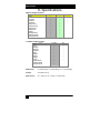
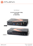
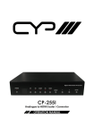
Multi-format HD Video Scaler
Model AC139A
UMA 1157 Rev C
Model AC139A
Multi-Format HD Video Scaler
Converts between HD and PC Video Formats
CUSTOMER
SUPPORT
INFORMATION
Order toll-free in the U.S. 24 hours, 7 A.M. Monday to midnight Friday: 877-877-BBOX
FREE technical support, 24 hours a day, and 7 days a week: Call 724-746-5500 or fax 724-746-0746
Mail order: Black Box Corporation, 1000 Park Drive, Lawrence, PA 15055-1018
Web site: www.blackbox.com • E-mail: [email protected]
1
Model AC139A
Trademarks Used in this Manual
BLACK BOX and its logo
are registered trademarks of Black Box
Corporation. Any other trademarks mentioned in this manual are
acknowledged to be the property of the trademark owners.
FCC and Canadian Dept of Communications Radio Frequency
interference statements
This equipment generates, uses, and can radiate radio frequency energy
and if not installed and used properly, that is, in strict accordance with the
manufacturer’s instructions, may cause interference to radio
communication. It has been tested and found to comply with the limits
for a Class A computing device in accordance with the specifications in
Subpart B of Part 15 of FCC rules, which are designed to provide
reasonable protection against such interference when the equipment is
operated in a commercial environment. Operation of this equipment in a
residential area is likely to cause interference, in which case the user at
there own expense will be required to take whatever measures may be
necessary to correct the interference. Changes or modifications not
expressly approved by the party responsible for compliance could void
the user’s authority to operate the equipment.
This digital apparatus does not exceed the Class A limits for radio noise
emission from digital apparatus set out in the Radio Interference
Regulation of the Canadian Department of Communications.
Le présent appareil numérique n’émet pas de bruits radioélectriques
dépassant les limites applicables aux appareils numériques de la classe
A prescrites dans le Règlement sur le brouillage radioélectrique publié
par le ministère des Communications du Canada.
European Union Declaration of Conformity
This product complies with the requirements of the European EMC
directive 89/336/EEC
2
Multi-format HD Video Scaler
Normas Oficiales Mexicanas (NOM)
Electrical Safety Statement
INSTRUCCIONES DE SEGURIDAD
1.
2.
3.
4.
5.
6.
7.
8.
9.
10.
11.
12.
13.
14.
15.
16.
17.
18.
A:
B:
C:
D:
E:
Todas las instrucciones de seguridad y operación deberán ser leídas antes de que el
aparato eléctrico sea operado.
Las instrucciones de seguridad y operación deberán ser guardadas para referencia
futura.
Todas las advertencias en el aparato eléctrico y en sus instrucciones de operación
deben ser respetadas.
Todas las instrucciones de operación y uso deben ser seguidas.
El aparato eléctrico no deberá ser usado cerca del agua—por ejemplo, cerca de la tina
de baño, lavabo, sótano mojado o cerca de una alberca, etc.
El aparato eléctrico debe ser usado únicamente con carritos o pedestales que sean
recomendados por el fabricante.
El aparato eléctrico debe ser montado a la pared o al techo sólo como sea recomendado
por el fabricante.
Servicio—El usuario no debe intentar dar servicio al equipo eléctrico más allá a lo
descrito en las instrucciones de operación. Todo otro servicio deberá ser referido a
personal de servicio calificado.
El aparato eléctrico debe ser situado de tal manera que su posición no interfiera su uso.
La colocación del aparato eléctrico sobre una cama, sofá, alfombra o superficie similar
puede bloquea la ventilación, no se debe colocar en libreros o gabinetes que impidan el
flujo de aire por los orificios de ventilación.
El equipo eléctrico deber ser situado fuera del alcance de fuentes de calor como
radiadores, registros de calor, estufas u otros aparatos (incluyendo amplificadores) que
producen calor.
El aparato eléctrico deberá ser connectado a una fuente de poder sólo del tipo descrito
en el instructivo de operación, o como se indique en el aparato.
Precaución debe ser tomada de tal manera que la tierra fisica y la polarización del
equipo no sea eliminada.
Los cables de la fuente de poder deben ser guiados de tal manera que no sean pisados
ni pellizcados por objetos colocados sobre o contra ellos, poniendo particular atención
a los contactos y receptáculos donde salen del aparato.
El equipo eléctrico debe ser limpiado únicamente de acuerdo a las recomendaciones
del fabricante.
En caso de existir, una antena externa deberá ser localizada lejos de las lineas de
energia.
El cable de corriente deberá ser desconectado del cuando el equipo no sea usado por
un largo periodo de tiempo.
Cuidado debe ser tomado de tal manera que objectos liquidos no sean derramados
sobre la cubierta u orificios de ventilación.
Servicio por personal calificado deberá ser provisto cuando:
El cable de poder o el contacto ha sido dañado; u
Objectos han caído o líquido ha sido derramado dentro del aparato; o
El aparato ha sido expuesto a la lluvia; o
El aparato parece no operar normalmente o muestra un cambio en su desempeño; o
El aparato ha sido tirado o su cubierta ha sido dañada.
3
Model AC139A
Contents
1. Introduction .......................................................................................... 5
1.1 General ........................................................................................... 5
1.2 Features .......................................................................................... 7
2. Installation............................................................................................ 8
2.1 Connecting the Video Inputs and Outputs...................................... 8
2.2 Other Connections........................................................................ 11
3. Configuration and Operation.............................................................. 12
3.1 Front Panel ................................................................................... 12
3.2 OSD Menus .................................................................................. 14
3.3 Infra-Red Remote control (IR Remote) ........................................ 17
3.4 IR Codes....................................................................................... 18
4. Serial Control ..................................................................................... 18
4.1 Read Commands........................................................................... 19
4.2 Key Commands ............................................................................ 19
4.3 Set Commands.............................................................................. 20
5. Troubleshooting ................................................................................. 21
Contacting Black Box ........................................................................ 21
Shipping and Packaging ..................................................................... 21
6. Specifications ..................................................................................... 22
4
Multi-format HD Video Scaler
1. Introduction
1.1 General
Thank you for purchasing the Black Box Model AC139A, a powerful
video processor and scaling product. It combines the functions of many
products in one compact and versatile unit. It has both high definition
analog as well as digital inputs. Two outputs are available
(simultaneously active†), one analog (RGBHV) and one digital DVI-D
(HDMI™ compatible).
Figure 1 – Block Diagram
The user can select the desired input using individual buttons on the front
panel, on the included IR-remote, or by issuing ASCII RS232 commands.
The output resolution can be set can range between 480i to 1080p for
HDTV, or VGA (640x480) to WUXGA (1920X1200) for the PC. The
unit uses the latest high-resolution video scaling techniques to produce a
superior video output for a crisp image on the output display. Both video
outputs can also be mirrored horizontally making it ideal for
teleprompting and rear projection systems where the image needs to be
.flipped.
The desired output resolution is set directly using individual buttons on
the IR remote, or via unique ASCII RS232 commands. The front panel
can also be used to set the output resolution. A user-friendly on-screendisplay (OSD) is used to control the operation of the device from the
front panel. There are also ‘hot-key’ combinations on the front panel to
directly set the output to basic PC or HDTV resolutions so that a picture
can be displayed on any LCD.
† For HDMI™ compliance, when the DVI input is selected, and HCDP content protection is
detected on the signal, the HD15 analog output is blanked. The front panel input LED will
blink when this condition is detected. The Digital DVI output will be active when connected to
a HDCP compliant LCD (such as a display with HDMI™ input).
5
Model AC139A
The DVI input is HDCP compliant. This allows the unit to be used as an
HDMI™ Video Scaler (HDMI™ audio is not passed through). When the
digital input has HDCP encryption, the DVI output must be connected to
a HDCP compatible LCD (by definition all displays with HDMI™ input
must be HDCP compliant).
Built-in universal power supply keeps the installations clutter free.
The unit can be used to convert and change resolution in the following
ways:
OUTPUT
INPUT
DVI
Notes:
6
HDMI (1)
DVI
HDMI (1)
YPbPr
(Component)
VGA (RGBHV)
(1) HDMI™ to DVI cable or adapter required
VGA
(RGBHV)
Multi-format HD Video Scaler
1.2 Features
•
High definition digital (DVI / HDMI) and analog (PC VGA / YPbPr)
Scaler that accepts PC RGB (up to UXGA), HD Component (480i
up to 1080p) and DVI (up to WUXGA) and scales them to DVI and
analog outputs at user specified resolutions
•
HDCP (HDMI™) compliant DVI input and output
•
Output resolution selectable from 480i to 1080p (HDTV) and VGA
to WUXGA (PC).
•
RS232 Control port, IR remote, and Front Panel Controls
•
Native output mode ensures optimal resolution on the screen based
on the display’s EDID.
•
Output picture adjustments for brightness, contrast, RGB levels
•
Output can be mirrored! Perfect for teleprompting or rear projection
applications
•
State of the art scaling engine for sharp and flicker free output
•
Built-in Universal Power Supply with standard IEC-320 jack
•
Compact, Rugged, Reliable, and Economical
•
Rack-mount brackets available
7
Model AC139A
2. Installation
2.1 Connecting the Video Inputs and Outputs
The video scaler can accept a VGA (analog RGBHV from PC), DVI
(digital video from PC or HDMI™ source), and Component Video (Y Pb
Pr) from any source.
When the source is from an HDMI™ output, an HDMI to DVI cable or
adapter is required. Please contact Black Box if you need to purchase this
cable.
Two outputs connectors are provided. Both show the selected input at the
desired output resolution.
Figure 2 - Rear Panel
Video cables for connecting the I/O ports are not supplied with the unit.
If you would like to mount the unit in a rack, please contact Black Box to
purchase a rack-mount accessory kit for the unit.
Figure 3 – Optional Rack-mount Kit
8
Multi-format HD Video Scaler
Video Inputs
Y Pb Pr: This is also known as Component Video input (analog) and on
some equipment it may be labeled as YCbCr. Since this input supports all
interlace and progressive resolutions from 480i to 1080p, you can
connect it to both legacy and new equipment alike as long as it has
component video output. For a list of supported resolutions, please see
Specifications Section titled “Supported Input Formats” found later in
this manual. For example; if you are using the DVI output of the scaler to
connect to the HDMI input of an HDTV, you could use the YPbPr input
to connect your legacy DVD player, or PlayStation™ equipment to your
HDTV.
VGA: This is the analog RGBHV signal from a PC. A wide range of
resolutions from VGA to WUXGA is supported. For a list of supported
resolutions, please see Specifications Section titled “Supported Input
Formats” found later in this manual. This input provides a convenient
way to display your PC’s video without losing clarity on any TV or
HDTV as long as the TV has either HDMI™ or component inputs. Since
the AC139A uses state of the art video scaling, often you will achieve a
sharper image on your LCD even if it has a VGA input!
DVI: This is the digital input to the Scaler. You can connect to the DVID or DVI-I outputs of any PC. The DVI input of the unit supports HDCP
encryption. This means that it is compatible with Content Protected
HDMI™ video sources. However, the audio of HDMI source is not
processed through and you should configure and use the separate audio
output of your HDMI™ source. The DVI input of the scaler can handle
most HDTV and PC resolutions. For a list, please see Specifications
Section titled “Supported Input Formats” found later in this manual.
Note about DVI input Cable
If you will be connecting to an HDMI™ source you will either need an
HDMI to DVI cable or an HDMI to DVI adapter.
Figure 4
Example of HDMI™ to DVI Cable
If you will be connecting to a DVI source you will then need a male to
male DVI cable. DVI-D cables will work since they do not have the
extra pins that DVI-I cables have, but since the AC139A utilizes a
9
Model AC139A
connector with all the pin positions you could use a DVI-I cable as long
as your source also has all the pin positions.
10
Multi-format HD Video Scaler
Video Outputs
VGA: This is a dual purpose output. Depending on the output resolution
you set it will output a PC compatible signal.
Note about HDCP
For HDMI™ compliance, if the input is from an HDMI™ source with
content protection, the VGA output is blanked and front panel LED
blinks.
DVI: This is the TMDS digital output of the Scaler. You can connect this
to any PC compatible LCD with a DVI compatible connector input, or
any HDTV with a HDMI™ compatible connector input using the
appropriate cable.
2.2 Other Connections
RS232: This 9-pin D-sub connector is for connecting to your PC or other
serial control device for remote control of the AC139A.
Scaler
PIN
Definition
2
TxD
3
RxD
5
GND
Interconnect Cable DB9
M/F
Remote Controller
PIN
Definition
2
RxD
3
TxD
5
GND
AC power jack: This is a standard IEC320 / C14 power connection. The
unit’s power supply is universal (90 ~ 264 Vac, 50 ~ 60 Hz).
11
Model AC139A
3. Configuration and Operation
3.1 Front Panel
5
1.
2.
3.
4
3
2
1
Figure 5 –
Front Panel
Power: Press this button to turn ON or turn OFF (standby) the
power to the unit.
Menu/Enter: This button serves two purposes.
A. Pressing the button will bring up the OSD main menu as
shown in the "OSD Menus" section of this manual.
B. To act as an "Enter" key to enter sub menu or to adjust setting
value of the selected parameter.
▲or▼ buttons: The buttons provide 3 functions:
A. Input Select (▲): Press the ▲ button repeatedly to select
your desired input source. The input sources are toggled through
in the following sequence.
Figure 6
Input Selection Sequence
4.
5.
12
B. Auto Tune (▼): Press the ▼ button to initiate picture auto
adjust for analog inputs (component or PC/VGA). The scaler
will fine tune the position (centering) and color of the output
picture.
C. When in the OSD menu mode: Press the ▲ or ▼ buttons to
move up or down the highlighted bar to the desired parameter.
Once a parameter is highlighted then press the MENU / Enter
button to adjust the setting.
Input LED Indicators: The illuminated LED indicates that
corresponding source is being selected as input.
IR Sensor: Infrared remote control sensor.
Multi-format HD Video Scaler
Front Panel Quick Selection “Hot Keys”
Figure 7
If you are not getting any image on your display, it could be that the
output resolution setting of the AC139A is not supported by your LCD.
Using serial commands or the IR remote, one can quickly switch between
various output resolutions. However since the front panel operation relies
on OSD menu for navigation, it is very difficult to change the output
setting from the front panel if you cannot see the OSD. Therefore to
quickly jump to a basic resolution that is supported by virtually all
displays, is a great feature.
If you press and hold down the MENU button, and then hit the ▲ button
you get a XGA output which is supported by most PC compatible
displays.
If you press and hold down the MENU button, and then hit the ▼ button
you get a 480p output which is supported by most HDTV compatible
displays.
13
Model AC139A
3.2 OSD Menus
Pressing the "MENU" button brings up the On-Screen Display (OSD)
main menu as shown below:
OSD Menu System
Video
Color
Output
OSD
Info
Contrast
Brightness
Hue
Saturation
Sharpness
Picture Mode
Scale
Mirror
Noise
Reduction
(H Position) †
(V Position) †
Exit
User
Normal
Warm
Cool
VGA
SVGA
XGA
SXGA
UXGA
WXGA
WSXGA
WUXGA
480i
480p
576i
576p
720p (50/60)
1080i (50/60)
1080p (50/60)
Native
H. Position
V. Position
Timeout
Background
Exit
Version
Input
Output
†
H and V Position are only available for VGA or component input
Use the▲ or ▼ buttons to move the highlight bar to the desired
parameter, and then press the MENU button to enter the sub-menu of the
selected parameter.
Video Submenu:
Figure 8
OSD Main Menu structure
Contrast
Brightness
Hue
Saturation
Picture Mode
Scale
Mirror
Noise Reduction
(H Position)
(V Position)
Exit
User
Standard
Vivid
Movie
Overscan
Underscan
Letterbox
Panscan
Full
Low
Middle
High
Off
14
Multi-format HD Video Scaler
To adjust the picture quality, use the▲ or ▼ buttons to move the
highlight bar to the desired item and then press the MENU to confirm
your selection. At this point, the selected parameter will turn red, you can
then use the ▲, ▼ buttons to increase or decrease the value of the
parameter. When the adjustment has been completed; press the MENU
button to leave that parameter. Move the highlight bar to EXIT, and then
press the MENU button to exit.
Note: The "H-position" and "V-position" are only available when the
component or PC (VGA) input is selected
Picture mode - There are 4 picture modes to choose from:
User: Select to adjust the parameters to your favorite levels and then
automatically store it.
Standard: Standard factory default settings for optimal display
Vivid: High saturation picture for optimal display in a bright room.
Movie: Picture for comfortable low brightness display in a dark room.
Scale - select over-scan when the input source is SD or HD video to
ensure there is no black band around screen boundary. Select under-scan
when input source is a PC signal to ensure entire contents (all the way to
the edge) are within the screen boundary.
Mirror – Select mirror to horizontally flip the image. This is useful for
teleprompting and rear projection systems.
Noise Reduction - This function only works when the input source is
analog RGB or component. It will not work for the DVI input. There are
four steps of Noise Reduction: Off, Low, Middle, High. The Noise
Reduction will remove the noise that results from the analog to digital
conversion and digital scaling process.
H & V position – Adjusts the horizontal and vertical position of the
image.
15
Model AC139A
Color Submenu:
User: Select to adjust to your favorite color temperature setting.
Normal: Normal color tone setting where white is pure white.
Warm: Warm color tone (white reddish).
Cool: Cool color tone (white bluish).
Output Submenu:
This submenu is used to set the desired output resolution. When Native is
selected the unit reads the native resolution of the connected LCD (via its
EDID) and sets its resolution to match it if possible. If both outputs are
connected (HD15 and DVI/HDMI™); then the native resolution of the
DVI display is used.
OSD Adjust Submenu:
H. Position: Adjust the horizontal position of the OSD graphic.
V. Position: Adjust the vertical position of the OSD graphic.
Time out: Set a predetermined time to turn off the OSD menu on the
screen.
Background: To select a transparent or solid background of the OSD
graphic.
Information Submenu:
Input: Shows the currently selected input resolution Example: XGA.
Output: Shows the currently selected output resolution. For Example:
720p.
Version: Shows the firmware version.
16
Multi-format HD Video Scaler
3.3 Infra-Red Remote control (IR Remote)
Power: Press the button once to power on
the AC139A. Press again to enter standby
mode.
Input: Press the button repeatedly to toggle
through the various input sources
HD: Press the button to select the
component input.
PC: Press the button to select the VGA
input.
HDMI/DVI: Press the button to select the
DVI input.
VGA through 1080p: Press any one of the
buttons to directly select the desired output
resolution. For other output resolutions that
are not covered by these buttons please enter
Menu/Output OSD page to select them.
MENU: Press the button to bring up the
OSD main menu page.
Exit: Press the button to exit from a sub
menu or the main menu.
Up/Down/Left/Right: Press the ▲ or ▼ buttons to move the highlight
bar to your desired parameter during the OSD operation. Press the or
buttons to increase or decrease the setting value of a selected
parameter.
OK (Enter): Press the button to confirm your selection.
Reset: Press the button to reset the unit to the factory default values.
Auto Adjust: Press the button to optimize the position of the picture
(picture centering) on the screen.
17
Model AC139A
3.4 IR Codes
The Infra-Red
Remote Control
codes are shown for
users that wish to
program their own
universal remote
control to control the
AC139A.
4. Serial Control
The video input selection and signal parameter settings for the AC139A
can be controlled via an external control system by using the RS232 port
on the unit. Use a straight thru M/F DB9 serial cable to connect the unit
to the PC. Only the TX, RX and GND pins are implemented in the
connector. The RS232 port operates at 19200 baud, no parity and 1 stop
bit. All commands are ASCII characters.
18
Multi-format HD Video Scaler
4.1 Read Commands
Command
R POWER
R SOURCE
R OUTPUT
R SIZE
R PICTUREMODE
R CONTRAST
R BRIGHTNESS
R HUE
R SATURATION
R SHARPNESS
R NR
R PCHPOSITION
R PCVPOSITION
R PCCLOCK
R PCPHASE
R COLORTEMP
R RED
R GREEN
R BLUE
R OSDHPOSITION
R OSDVPOSITION
R OSDTIMEOUT
R MIRROR
R OSDBACKGROUND
Response
> POWER ON or POWER OFF
> SOURCE Comp, PC, DVI
> OUTPUT NATIVE~WUXGA
> SIZE FULL~PANSCAN
> PICTUREMODE
STANDARD~USER
> CONTRAST 0~100
> BRIGHTNESS 0~100
> HUE 0~100
> SATURATION 0~100
> SHARPNESS 0~100
> NR OFF~HIGH
> PCHPOSITION 0~100
> PCVPOSITION 0~100
> PCCLOCK 0~100
> PCPHASE 0~63
> COLORTEMP NORMAL~USER
> RED 0~100
> GREEN 0~100
> BLUE 0~100
> OSDHPOSITION 0~100
> OSDVPOSITION 0~100
> OSDTIMEOUT 0~100
> MIRROR ON or MIRROR OFF
> OSDBACKGROUND 0~8
Description
SHOW POWER STATUS
SHOW SOURCE STATUS
SHOW OUTPUT STATUS
SHOW SIZE STATUS
SHOW PICTURE MODE STATUS
SHOW CONTRAST STATUS
SHOW BRIGHTNESS STATUS
SHOW HUE STATUS
SHOW SATURATION STATUS
SHOW SHARPNESS STATUS
SHOW NR STATUS
SHOW PC H-POSITION STATUS
SHOW PC V-POSITION STATUS
SHOW PC COLOK STATUS
SHOW PC PHASE STATUS
SHOW COLOR TEMP STATUS
SHOW COLOR TEMP RED STATUS
SHOW COLOR TEMP GREEN STATUS
SHOW COLOR TEMP BLUE STATUS
SHOW OSD H-POSITION STATUS
SHOW OSD V-POSITION STATUS
SHOW OSD TIMEOUT STATUS
SHOW MIRROR STATUS
SHOW OSD BACKGROUND STATUS
An invalid command will respond with “R-[??]”<CR>
4.2 Key Commands
Command
K POWER
K MENU
K UP
K DOWN
Response
> POWER
> MENU
> UP
> DOWN
Description
PRESS POWER BUTTON
PRESS MENU BUTTON
PRESS UP BUTTON
PRESS DOWN BUTTON
An invalid command will respond with “K-[??]”<CR>
19
Model AC139A
4.3 Set Commands
Command
S POWER 0
S POWER 1
S SOURCE 0
S SOURCE 1
S SOURCE 2
S OUTPUT 0
S OUTPUT 1
S OUTPUT 2
S OUTPUT 3
S OUTPUT 4
S OUTPUT 5
S OUTPUT 6
S OUTPUT 7
S OUTPUT 8
S OUTPUT 9
S OUTPUT 10
S OUTPUT 11
S OUTPUT 12
S OUTPUT 13
S OUTPUT 14
S OUTPUT 15
S OUTPUT 16
S OUTPUT 17
S OUTPUT 18
S SIZE 0
S SIZE 1
S SIZE 2
S SIZE 3
S SIZE 4
S PICTUREMODE 0~3
S CONTRAST 0~100
S BRIGHTNESS 0~100
S HUE 0~100
S SATURATION 0~100
S SHARPNESS 0~100
S NR 0~3
S PCHPOSITION 0~100
S PCVPOSITION 0~100
S PCCLOCK 0~100
S PCPHASE 0~63
S COLORTEMP 0~3
Response
> POWER OFF
> POWER ON
> SOURCE COMP
> SOURCE PC
> SOURCE DVI
> OUTPUT NATIVE
> OUTPUT VGA
> OUTPUT SVGA
> OUTPUT XGA
> OUTPUT SXGA
> OUTPUT UXGA
> OUTPUT 480I
> OUTPUT 480P
> OUTPUT 720P
> OUTPUT 1080I
> OUTPUT 1080P
> OUTPUT 576I
> OUTPUT 576P
> OUTPUT 720P
> OUTPUT 1080I50
> OUTPUT 1080P50
> OUTPUT WXGA
> OUTPUT WSXGA
> OUTPUT WUXGA
> SIZE FULL
> SIZE OVERSCAN
> SIZE UNDERSCAN
> SIZE LETTERBOX
> SIZE PANSCAN
> PICTUREMODE
STANDARD~USER
> CONTRAST 0~100
> BRIGHTNESS 0~100
> HUE 0~100
> SATURATION 0~100
> SHARPNESS 0~100
> NR OFF~HIGH
> PCHPOSITION 0~100
> PCVPOSITION 0~100
> PCCLOCK 0~100
> PCPHASE 0~63
> COLORTEMP NORMAL~USER
S RED 0~100
> RED 0~100
S GREEN 0~100
> GREEN 0~100
S BLUE 0~100
> BLUE 0~100
S OSDHPOSITION 0~100
> OSDHPOSITION 0~100
S OSDVPOSITION 0~100
> OSDVPOSITION 0~100
S OSDTIMEOUT 0~100
> OSDTIMEOUT 0~100
S MIRROR 0
S MIRROR 1
S OSDBACKGROUND 0~8
MIRROR OFF
MIRROR ON
> OSDBACKGROUND 0~8
S RESET 1
> RESET ON
An invalid command will respond with “S-[??]-[xx]”<CR>
20
Description
POWER OFF
POWER ON
COMPONENT INPUT
PC INPUT
DVI INPUT
NATIVE RESOLUTION OUTPUT
VGA RESOLUTION OUTPUT
SVGA RESOLUTION OUTPUT
XGA RESOLUTION OUTPUT
SXGA RESOLUTION OUTPUT
UXGA RESOLUTION OUTPUT
480I RESOLUTION OUTPUT
480P RESOLUTION OUTPUT
720P 60HZ RESOLUTION OUTPUT
1080I 60HZ RESOLUTION OUTPUT
1080P 60HZ RESOLUTION OUTPUT
576I 60HZ RESOLUTION OUTPUT
576P 60HZ RESOLUTION OUTPUT
720P 50HZ RESOLUTION OUTPUT
1080I 50HZ RESOLUTION OUTPUT
1080P 50HZ RESOLUTION OUTPUT
WXGA RESOLUTION OUTPUT
WSXGA RESOLUTION OUTPUT
WUXGA RESOLUTION OUTPUT
SCALER FULL OUTPUT
SCALER OVERSCAN OUTPUT
SCALER UNDERSCAN OUTPUT
SCALER LETTERBOX OUTPUT
SCALER PANSCAN OUTPUT
0:STANDARD ; 1:MOVIE ; 2:VIVID ; 3:USER
,PICTURE MODE OUTPUT
CONTRAST 0~100 ADJUST [Default:50]
BRIGHTNESS 0~100 ADJUST [Default:45]
HUE 0~100 ADJUST [Default:50]
SATURATION 0~100 ADJUST [Default:60]
SHARPNESS 0~100 ADJUST [Default:32]
0:OFF ; 1:LOW ; 2:MID ; 3:HIGH ,NR CONTROL
H POSITION 0~100 ADJUST
V POSITION 0~100 ADJUST
PC MODE COLCK 0~100 ADJUST
PC MODE PHASE 0~63 ADJUST
0:NORMAL ; 1:WARM ; 2:COOL ; 3:USER ,COLOR
TEMP SETTING
COLOR TEMP "RED" ADJUST
[Defaut:47]
COLOR TEMP "GREEN" ADJUST
[Defaut:47]
COLOR TEMP "BLUE" ADJUST
[Defaut:47]
OSD H POSITION 0~100 ADJUST
[Defaut:50]
OSD V POSITION 0~100 ADJUST
[Defaut:50]
OSD TIMEOUT 0~100 SETTING
[Defaut:10]
TURN HORIZONTAL MIRRORING OFF
TURN HORIZONTAL MIRRORING ON
OSD OSDBACKGROUND 0~8 ADJUST
[Defaut:5]
RESET ACTION
Multi-format HD Video Scaler
5. Troubleshooting
There are no field serviceable parts or circuits in the device. If you think
that the device is malfunctioning, please first try to reset to the factory
default settings (using the RESET button on the IR remote control), and
set the output either to XGA (Press MENU + ▲) or 480p (Press MENU
+ ▼) to obtain an image on your LCD.
If you are having trouble displaying a picture from an HDMI™ source,
ensure that the display device connected to the AC139A is HDCP
compliant.
For HDMI™ compliance, when the DVI input is selected, and HCDP
content protection is detected on the signal, the HD15 analog output is
blanked. The front panel input LED will blink when this condition is
detected. The Digital DVI output will be active when connected to a
HDCP compliant LCD (such as a display with HDMI™ input).
Contacting Black Box
If you determine that your scaler is malfunctioning, do not attempt to
repair the unit. There are no user serviceable parts inside the unit.
Opening the unit will void the warranty. Contact Black Box at 724-7465500. Before you do, make a record of the problem. We will be able to
provide more efficient and accurate assistance if you have a complete
description.
Shipping and Packaging
If you need to transport or ship your scaler:
• Package it carefully. Use the original container if possible.
• Before you shipping the unit, contact us to get a Return
Authorization (RA) number.
21
Model AC139A
6. Specifications
Supported Input Formats:
DVI / HDMI™
VGA (PC)
480i/576i
Resolution
YPbPr
480p/576p
720p@(60/50)
1080i@(60/50)
1080p@(60/50)
VGA@(60/72/75/85)
SVGA@(56/60/72/75/85)
XGA@(60/70/75/85)
SXGA@(60/75/85)
UXGA@60
WXGA@60(1280X800)
WSXGA@60(1680X1050)
WUXGA@60(1920X1200)
Available Output Formats:
480i/576i
Resolution
DVI / HDMI™
HD-15
480p/576p
720p@(60/50)
1080i@(60/50)
1080p@(60/50)
VGA@60
SVGA@@60
XGA@@60
SXGA@@60
UXGA@60
WXGA@60(1280X800)
WSXGA@60(1680X1050)
WUXGA@60(1920X1200)
Dimensions:
9.4 inch (Wide) x 5.0 inch (Deep) x 1.75 inch (High)
Weight:
2 Pounds (910 g)
Input Power:
90 ~ 264 Vac, 50 ~ 60 Hz (7.5 watts max)
22
© Copyright 2011. Black Box Corporation. All rights reserved.
1000 Park Drive
Lawrence, PA 15055-1018
724-746-5500
Fax 724-746-0746