1
CB1 CHATTERBOX
VOICE RECORDER
Ramsey Electronics Model No.
CB1
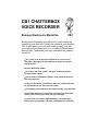
Getting tired of repeating yourself? Find yourself saying the
same thing over and over? Here's the answer to your prayers!
This kit will repeat your voice with amazing clarity over and
over, without ever getting tired, in a number of different ways!
Not only that, it preserves your voice even when the power is
turned off.
• 20 seconds of recording time available in five, four second
messages. Messages can be combined for longer record and
playback times.
• Loud 2 Watt audio output.
• Very clean, low noise “DAST” storage technology provides
excellent audio quality.
• Seven modes of operation available. Even interfaces to radios
and computers too!
• Fully microprocessor controlled for easy use, no diodes to add no dip switches to set. Easy and fun to use!
• LED displays show addresses and modes quickly, no guesswork.
• Compatible with most transceivers and works with most radio
mikes. It will even key your radio with your message.
• Can be used for: memos, HAM contesting, real estate sales,
leaving the kids messages, CB radio...possibilities are unlimited!
CB-1 • 1
RAMSEY TRANSMITTER KITS
· FM100 Professional FM Stereo Transmitter
· FM25 Synthesized Stereo Transmitter
·AM1, AM25 AM Transmitters
· TV6 Television Transmitter
RAMSEY RECEIVER KITS
· FR1 FM Broadcast Receiver
· AR1 Aircraft Band Receiver
· SR2 Shortwave Receiver
· AA7 Active Antenna
· SC1 Shortwave Converter
RAMSEY HOBBY KITS
· SG7 Personal Speed Radar
· SS70A Speech Scrambler
· ECG1 Heart Monitor
· WCT20 Wizard Cable Tracer
· PG13 Plasma Generator
· LABC1 Lead Acid Battery Charger
RAMSEY AMATEUR RADIO KITS
· FX146 VHF Transceivers
· HR Series HF All Mode Receivers
· QRP Series HF CW Transmitters
· CW700 Micro Memory CW Keyer
· CPO3 Code Practice Oscillator
· Packet Computer Interfaces
· QRP Power Amplifiers
RAMSEY MINI-KITS
Many other kits are available for hobby, school, Scouts and just plain FUN.
New kits are always under development. Write or call for our free Ramsey
catalog.
CB-1 CHATTERBOX KIT INSTRUCTION MANUAL
Ramsey Electronics publication No. MCB-1 Revision 2.1a
First printing: April 1994
COPYRIGHT 1994 by Ramsey Electronics, Inc. 793 Canning Parkway, Victor, New York
14564. All rights reserved. No portion of this publication may be copied or duplicated without the
written permission of Ramsey Electronics, Inc. Printed in the United States of America.
CB-1 • 2
Ramsey Publication No. MCB1
Price $5.00
KIT ASSEMBLY
AND INSTRUCTION MANUAL FOR
CB1 CHATTERBOX
RECORDER KIT
TABLE OF CONTENTS
Introduction to the CB-1 ................ 4
How it works .................................. 5
Parts list ........................................ 7
CB-1 Assembly instructions .......... 8
Initial testing ................................ 17
Troubleshooting ........................... 18
Using the CB-1 ............................. 19
Microphone considerations .......... 20
Parts Layout diagram .................. 21
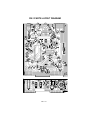
Schematic diagram ..................... 22
RAMSEY ELECTRONICS, INC.
793 Canning Parkway
Victor, New York 14564
Phone (716) 924-4560
Fax (716) 924-4555
www,ramseykits.com
CB-1 • 3
CB-1 CHATTERBOX VOICE RECORDER FEATURES
• LED display for mode and address
• Up to five separate four second addresses can be accessed
• Easy to use microprocessor control
• Seven modes available:
Mode 1: Play selected message once.
Mode 2: Play through messages until button is released.
Mode 3: Play selected message over and over while start button is
depressed.
Mode 4: Play through all of memory starting at selected address.
Mode 5: Play one message upon release of the button.
Mode 6: Record until the button is released.
Mode 7: Disable mode.
• 12VDC operation
• Loud 2 Watt audio output
• Designed to operate with a radio transceiver or stand alone
• Will even appropriately key your radio to output a message after each
transmission
• Ideal for contests, repeaters, CB radio or any other application that
requires repetitive speech or sounds
INTRODUCTION TO THE RAMSEY CB-1 VOICE RECORDER
We're sure you've found that it gets tiring repeating what you have just said
over and over again, whether you are contesting, or just simply using your
radio a lot. This kit can take care of the tiresome tasks such as saying "Over
and out", a call sign, CQ, your QTH or whatever. Not only is this kit useful for
repeating messages, but it is very easy to record with also. You simply select
the record mode, press a button, and it instantly records sound through the
built-in microphone. If desired, you may connect up an external microphone
of your choice. Since this circuit records electronically, there is no rewinding
or resetting to wait for, everything is near instantaneous. Since the audio
quality of this kit is very good, your listeners will hardly be able to tell the
difference between your original voice and the recorded voice.
Not only will you find this kit very useful, you'll also find it enjoyable to build,
whether you are a beginner or an experienced kit builder.
NOTE TO NEWCOMERS: If you are a first time kit builder you may find this
manual easier to understand than you may have expected. Each part in the
kit is checked off as you go, while a detailed description of each part is given.
If you are to follow each step in the manual in order, and practice good
soldering and kit building skills, the kit is next to fail-safe. If a problem does
CB-1 • 4
occur, the manual will lead you through step by step in the troubleshooting
guide until you find the problem and are able to correct it.
CIRCUIT DESCRIPTION
Most of the difficult work in this circuit is performed by the ISD1020 voice
recorder IC chip (U4) and the MC68HC705 series microprocessor (U3).
These two ICs "talk" (yes, pun intended!) to each other to access the different
addresses, modes, when to start playback and record on U4. Not only does
the microprocessor control this, but it also runs the two displays, scans the
switches, and provides for a user friendly interface - not bad for a little 16 pin
chip.
The pins PA5, PA6, and PA7 of the microprocessor do a number of tasks.
They not only select the address of where playback and record is to be done,
but at the same time drive U1 to display the information of what address and
mode is selected. PB0 selects which display is turned on. The two displays
are not actually on at the same time, but are switched fast enough by the
microprocessor so that they appear to the eye to be on continuously. PA0
through PA2 scan the switches for mode, play, and address. PA3 chip
selects the voice recorder, and through the pulse shaping circuit of Q7, resets
the ISD1020 IC chip.
The SP output of the ISD1020 is taken through volume control, POT1 and
then fed into the audio speaker driver U2 for amplification. Amplifier U2
provides 2 watts of audio output, capable of driving a speaker to excellent
volume. A simple keying detection scheme consisting of Q8, Q9, and
surrounding components allows sensing of an external microphone's push-to
talk switch. This circuitry simulates the pressing of the play button when there
is a resistive loading effect caused by the keying of the mike. The advantage
of this system is that it allows you to use your existing radio microphone to
activate playback and record.
PB1 on the microprocessor is the line that controls the keying of a connected
transceiver. When the voice recorder is activating your transceiver, decimal
points on the display are illuminated to let you know. Transistors Q1 and Q2
are connected as a Darlington pair to key the radio, and R7 is optional for
either a resistive loading type of keying, or a simple pull down scheme. VR1
is a three terminal voltage regulator to provide the +5 volts required by the IC
circuitry and the microprocessor.
CB-1 • 5
RAMSEY "LEARN-AS-YOU-BUILD RECORDER ASSEMBLY STRATEGY"
The CB-1 voice recorder kit includes two PC boards, one being the main
board and the other a display board. They are mounted at a 90 degree angle
to each other so that the display may be easily read from the front of the kit.
It is obvious that if you were to place these boards together before mounting
all of your parts, it would make further assembly very difficult. For this reason
it is advisable to follow the step-by-step instructions in the manual and not
jump ahead.
We'll start building in one corner and work our way across, installing the
lower components up to the taller sized components. This will make our
placing and soldering of components easy. As we go along we'll attempt to
describe the circuit operation and the function of many of the parts.
Be sure to read through all of the steps, and check the boxes as you go to be
sure you didn't miss any important steps. Before you switch on the power in a
hurry to see results, check all diodes, ICs, and capacitors for proper
orientation. Also check the board for any possible solder shorts or cold solder
joints. All of these mistakes could have detrimental effects on your kit - not to
mention your ego!
Kit building tips:
Use a good soldering technique - let your soldering iron tip gently heat the
traces to which you are soldering, heating both wires and pads
simultaneously. Apply the solder on the iron and the pad when the pad is hot
enough to melt the solder. The finished joint should look like a drop of water
on paper, somewhat soaked in.
Mount all parts on the top side of the board. This is the side that has no
traces or pads on it.
IC sockets - A good practice, but not necessary in digital or low frequency
circuits. This prevents the horror of desoldering a bad or incorrectly placed
IC.
Note: Do not use a socket for U1, as this interferes with a front panel if one is
to be used.
Part orientation - All parts in the kit are mounted at 90 degree angles to each
other, meaning that all parts are either parallel or perpendicular to the board.
Part installation - when parts are installed, the part is placed flat to the board,
and the leads are bent on the backside of the board to prevent the part from
falling out before soldering. The part is then soldered securely to the board,
and the remaining lead length is then clipped off.
CB-1 • 6
RAMSEY CB-1 CHATTERBOX PARTS LIST
SEMICONDUCTORS
r 1 ISD1020A sound recorder IC [U4]
r 1 MC68HC705K1 microprocessor IC [U3], 16 pin IC with white sticker
r 1 LM380 2 watt audio amplifier IC chip [U2]
r 1 MC14511 (4511) BCD to 7 segment IC chip [U1]
r 1 7805 5 volt regulator [VR1]
r 7 2N3904 NPN transistor [Q1,2,4,5,6,7,9]
r 1 221334 PNP (2N3906 type) transistor [Q8]
r 1 1N4148 style silicon diode (glass body with black band) [D2]
r 2 7 segment displays [DS1,2]
CAPACITORS
r 7 .01uF disc ceramic (marked .01 or 103 or 10 nF) [C1,5,6,13,17,19,20]
r 4 .1uF disc ceramic (marked .1 or 104) [C4,8,11,18]
r 1 100pF disc ceramic (marked 100 or 101) [C10]
r 2 1uF electrolytic [C9,14]
r 3 10uF electrolytic [C2,7,16]
r 2 220uF electrolytic [C3,15]
RESISTORS
r 1 2 ohm resistor (red-black-gold) [R13]
r 2 75 ohm resistor (violet-green-black) [R2,3]
r 5 1K ohm resistor (brown-black-red) [R4,5,8,24,25]
r 3 2.2K ohm resistor (red-red-red) [R7,17,26]
r 4 4.7K ohm resistor (yellow-violet-red) [R9,10,18,19]
r 9 10K ohm resistor (brown-black-orange) [R1,11,14,15,20,21,22,23]
r 1 470K ohm resistor(yellow-violet-yellow) [R16]
r 1 10K ohm potentiometer (marked 103) [R6]
MISCELLANEOUS
r 1 5-Pin DIN Connector [J1]
r 1 Electret condenser microphone [MK1]
r 1 Power jack [J4]
r 2 Mini jacks [J2,3]
r 1 Switched potentiometer [POT1]
r 3 Push button switches [S1,2,3]
r 16" red hook-up wire
r 16" white hook-up wire (the color of this wire may vary due to supply- use
whatever color is supplied)
r 16" black hook-up wire
r 5" Buss wire (to be used in place of spare leads if they are used up)
r 1 28 pin IC socket
r 1 16 pin IC socket
REQUIRED, NOT SUPPLIED
CB-1 • 7
CONSTRUCTION OF THE CB-1 VOICE RECORDER
The first thing we will do is locate the two PC boards used with this kit, and
then find where we will be starting construction. The smaller board, with the
3/8" hole in it, is called the display board. We'll construct it last since it has
finer traces, and a little practice on the bigger board will be of help. The
larger logic board is where we'll be starting.
If the two boards have not been separated already, you will want to separate
them before you start. To do this, simply place the board on the surface of a
table. Line up the area between the two boards over the edge of the table.
Pushing down evenly and carefully break the two boards apart. It is very
important to do this carefully. Breaking the board in the wrong spot will let
the chatter out of your chatterbox before you even begin to build it! Next,
take a file or emery board and smooth out any leftover material. When you
connect the two boards together later, a smooth edge is very important.
r
1. Install power jack J4, soldering all three pins.
r
2. Install voltage regulator VR1, 7805. Observe correct placement of the
metal tab. Mount it so the lettering on the case is facing the edge of the
board. The 7805 provides a stable source of 5 volts for the various IC
chips.
r
3. Install C16, 10uF electrolytic capacitor. Electrolytic capacitors are
polarized and must be installed correctly. They are usually marked with a
black stripe and a ( - ) indicating their negative lead, while PC boards will
usually indicate the ( + ) hole.
r
4. Install C18, .1uF disc capacitor (marked .1 or 104). This part helps
shape the resetting pulses for U4. This capacitor is a disc ceramic type
which has no polarity markings, so you may install it either way.
r
5. Install Q7, 2N3904 NPN transistor. Notice the shape of the transistor.
The flat side must face the back of the board. This part helps to shape
the resetting pulses to U4.
r
6. Install R18, 4.7K ohm resistor (yellow-violet-red).
r
7. Install R19, 4.7K ohm resistor (yellow-violet-red).
r
8. Install C15, 220uF electrolytic capacitor. Observe correct polarity. This
part helps smooth out the 12VDC input to the regulator, and to the audio
amplifier chip U2.
r
9. Install C11, .1uF ceramic disc capacitor (marked .1 or 104). This part
helps reduce internal noise in the ISD1020 chip.
CB-1 • 8
r
10. Install C19, .01uF disc capacitor (marked .01 or 103 or 10nF). This
capacitor prevents DC voltage on the microphone from entering the
ISD1020 IC chip. A capacitor allows AC signals such as voice to pass
through, but blocks any DC voltage.
r
11. Install jumper JMP7. Use a scrap piece of clipped off component
lead wire bent into a wire staple shape. Jumpers act as electronic
"bridges" carrying signals over other circuit traces on the circuit board.
r
12. Install R16, 470K ohm resistor (yellow-violet-yellow). This part
combined with C14 provides for proper timing in the automatic gain
control circuitry internal to the ISD chip.
r
13. Install C14, 1uF electrolytic capacitor. Observe correct polarity.
r
14. Install C9, another 1uF electrolytic capacitor, with correct polarity.
r
15. Now that your soldering skills are good and warmed up, it's time to
install the 28 pin socket that U4 (ISD1020A) is inserted into. Sockets
aren’t absolutely necessary here, but they are a good idea. However,
they are difficult to install and care must be taken to do this task
correctly! Carefully insert it into the PC board and look at the back side
of the board to verify that all 28 pins are sticking through the board
before soldering. After you check that all 28 pins are properly in place,
solder all pins. Be very careful in soldering since some of the pins are
close to traces and a little too much solder can lead to a solder short.
When you are done, double check all of your solder joints for bridges,
especially around pins where there are traces running nearby. When
everything checks out OK, insert U4 into the socket, checking the
orientation, and making sure that none of the pins are bent under.
r
16. Install R21, 10K ohm resistor (brown-black-orange). This part also
helps shape reset pulses.
r
17. Install D2, 1N4148 type small signal diode (glass body with black
band). Install it with the cathode band as shown. Diodes are polarity
sensitive and their cathode bands must be installed in the correct
direction. This diode insures that only positive-going reset pulses will
appear on the ISD chip.
r
18. Install jumpers JMP6 and JMP9 using scrap component lead wire.
r
19. Install R14, 10K ohm resistor (brown-black-orange). R14 and C8
provide a reset signal to microprocessor U3 upon power up.
r
20. Install jumpers JMP2 and JMP4.
r
21. Install R15, a 10K ohm resistor (brown-black-orange). This resistor,
combined with C1,5 and 17, filters some of the "bounce" from the control
CB-1 • 9
switches. Switch bounce is literally mechanical bounce that results from
the pressing of the switch. High speed electronic circuits will see this
bouncing and will respond as though the switch was depressed many
times very quickly. Typical switch bounce is in the 10 to 20 millisecond
range (that's 10 to 20 thousandths of a second!).
r
22. Install R11, 10K ohm resistor (brown-black-orange).
r
23. Install R1, 10K ohm resistor (brown-black-orange).
r
24. Install C1, .01uF disc capacitor (marked .01 or 103 or 10nf).
r
25. Install C5, .01uF disc capacitor (marked .01 or 103 or 10nF).
r
26. Install C17, another .01uF disc capacitor (marked .01 or 103 or
10nF).
r
27. Install C8, .1uF ceramic disc capacitor (marked .1 or 104).
r
28. Install a 16 pin IC socket at location U3. Take care to do it
correctly! Like before, check that all 16 pins are correctly inserted into
the PC board before soldering. Double check for solder bridges when
finished soldering. This is where the microcontroller chip (the IC with the
sticker on top, or marked XC705K1P) is to be inserted. Insert U3 into the
socket, being careful of bent-under pins.
r
29. Install jumper JMP1.
r
30. Install R9, 4.7K ohm resistor (yellow-violet-red). This is a current limit
resistor that limits the amount of current to transistors Q1 and Q2, which
in turn key the radio output.
r
31. Install Q9, 2N3904 NPN transistor. Observe the correct orientation of
the flat side. This transistor is part of the PTT key detect circuit if you use
a radio mike.
r
32. Install R10, 4.7K ohm resistor (yellow-violet-red).
r
33. Install Q6, 2N3904 NPN transistor, observing the orientation of the
part. Q6 is part of the LED display driving circuit.
r
34. Install R5, 1K ohm resistor (brown-black-red).
r
35. Install Q4, another 2N3904 transistor. Make sure that the flat side is
facing R5.
r
36. Install R4, 1K ohm resistor (brown-black-red).
r
37. Install Q5, yet another 2N3904 transistor. Still watching the position
of the flat side, aren't you?
r
38. Install R8, 1K ohm resistor (brown-black-red).
CB-1 • 10
The circuitry you're working on now is the display driving circuit. When the
input to the circuit is low (near ground or zero volts), Q6 is off, which turns Q4
on, turning on only the address display. When the input is high (near +5V),
Q5 turns on and only the mode display is on. When the circuit is operating,
this switching is fast enough that it can't be seen by the eye (about 100 to
1000 times a second). This technique is called Multiplexing and is used with
virtually all displays, from calculators to TV sets!
r
39. Install R22, 10K ohm resistor (brown-black-orange).
r
40. Install jumper JMP10.
Whew! You're halfway done with the main board. Take a break to give your
eyes a rest. When you come back, check all of your solder connections,
looking for bridges or cold solder joints. Don't be afraid to reheat any of the
solder joints that you find suspicious; all parts in this kit would be almost
impossible to damage with extra heating. The only thing you have to watch
for when soldering are the PC board traces overheating and lifting off of the
circuit board.
r
41. Install Q1, 2N3904 transistor. Watch the positioning of the flat side.
r
42. Install Q2, 2N3904 transistor, watching the positioning of the flat side.
Transistors Q1 and Q2 are used to key an external radio.
r
43. Install C20, .01uF disc capacitor (marked .01 or 103 or 10nF). This is
a bypass capacitor which prevents noise from the operation of the
microprocessor from finding its way back into the power source.
r
44. Install jumper JMP8.
r
45. Install C13, .01uF ceramic capacitor (marked .01 or 103 or 10nF).
This part acts as a DC blocking capacitor to the mike input of the ISD
chip (same as the function of C19 earlier). This blocks the DC from the
key detecting circuit and mike line.
r
46. Install R23, 10K ohm resistor (brown-black-orange). This part,
combined with Q8, Q9, R22, R20, and R17, pulls the start line low when
there is a resistive load placed across the mike input, this has the same
effect as pressing the start switch. PA2 of the processor detects this and
activates accordingly.
r
47. Install jumper JMP3.
r
48. Install Q8, 221334 PNP type transistor. Notice that this transistor
does not have a fully rounded side like the others, but a semi-rounded
side and a fully flat side. You can most easily identify the flat side by
noting that the round side does have a curve to it on the side edges.
CB-1 • 11
r
49. Install R7, 2.2K ohm resistor (red-red-red). This part plays a role in
the keying of an attached radio. Depending on what type of microphone
your radio requires depends on whether or not this resistor is used. In all
of the Ramsey FX series transceivers and most handhelds, the resistor
is required. We'll look at this part later when we get to the
MICROPHONE CONSIDERATIONS section.
r
50. Install R17, 2.2K ohm resistor (red-red-red).
r
51. Install R20, 10K ohm resistor (brown-black-orange).
r
52. Install C6, .01uF disc ceramic (marked .01 or 103 or 10nF).
r
53. Install R24, 1K ohm resistor (brown-black-red). Notice that this
resistor stands upright.
r
54. Install C10, 100pF disc capacitor (marked 100 or 101). This
component combined with R24 determines the clock speed of the
processor. If you power up the circuit later and you can see the displays
flickering, check these two components for correct installation.
r
55. Install C7, 10uF electrolytic capacitor. Pay attention to polarity. This
is a DC blocking capacitor for the audio out of the ISD chip.
r
56. Install U2, LM380 audio amplifier IC. Observe correct orientation of
the part.
r
57. Install C2, 10uF electrolytic capacitor. Observe correct polarity. This
part couples external mike audio to the audio amplifier.
r
58. Install R6, 10K ohm potentiometer (marked 103).
r
59. Install R26, 2.2K ohm resistor (red-red-red).
r
60. Install C4, .1uF disc ceramic capacitor (marked .1 or 104).
r
61. Install R13, 2 ohm resistor (red-black-gold). This component
combined with C4 prevents U2 from going into high frequency
oscillations.
r
62. Install C3, 220uF electrolytic capacitor. Pay attention to the polarity.
C3 is the audio output coupling capacitor.
r
63. Install J2 and J3, both 1/8" mini jacks on the rear of the board. J2 is
the speaker output, J3 is the keyed mike input.
r
64. Install J1, five pin DIN jack. This jack is where you may interface your
radio with the CB-1 voice recorder.
Congratulations! You have just completed construction of the main board.
CB-1 • 12
Take a break and get your soldering skills saved up for the construction of
the display board. Locate the small display board and install the following
parts:
r
65. Install U1, a 4511, BCD to 7 segment display driver IC. Do not use a
socket for this part since it must sit below the LED displays. Observe
correct orientation.
r
66. Install jumper JMP5.
r
67. Install DS2, one of the LED displays. Notice the decimal point faces
the lower right of the board. This is where the soldering becomes difficult.
The pads are very close to the traces, and solder bridges are easier to
make. A small tipped soldering iron with a clean tip (wipe it often on a
damp sponge) is required for best results. This is where patience really
counts!
r
68. Install R3, 75 ohm resistor (violet-green-black). This is a current
limiting resistor for DS2.
r
69. Install LED display DS1 use the same care that you used for
installing DS2.
r
70. Install R2, 75 ohm resistor (violet-green-black). This is another
current limiting resistor.
r
71. Install S2, one of the mini push button switches. It should sit neatly
above the board. S2 selects the desired message’s address.
r
72. Install S1, the mini push button switch for selecting the mode.
r
73. Install S3, the last mini push button switch. S3 is the PLAY switch.
r
74. If you are planning to use this kit in the stand alone mode (without
hook-up to a radio transceiver), install MK1. This is the small microphone
in the silver can with black top. Look closely at the mike and notice how
the pins are off center. The mike must be installed as shown in the parts
layout diagram.
r
75. Install R25, 1K ohm resistor (brown-black-red). This resistor supplies
power to the microphone.
Now is a good time to check out all of your solder joints, on both the main
board and your display board, also check for proper part orientation and
polarity.
r
76. Locate POT1, the switched potentiometer. Mount the potentiometer
CB-1 • 13
from the backside of the display board through the 3/8" hole. The tab on
the potentiometer must be removed. Attach the mounting hardware
securely.
r
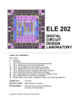
77. Here's the tricky part of assembly - mounting the display board to the
main board. The most important part of this step is achieving a nice right
angle between the display board and the main board.
Align the main board with the display board and notice how the pads on
each board line up with each other. To assist with assembly, as well as
provide mechanical stiffness, solder a piece of scrap wire supplied with the
kit between jumper point JMP-A on the main board and the display board.
Be sure that the PC boards are seated at right angles. Do the same for JMPB.
r
78. You can now use the wires to hold the boards at exact 90 degree
angles. When the PC boards are lined up, carefully begin to solder each
pad joining with a small amount of solder. The solder will flow nicely
between the two PC board pads. After you have soldered one or two
joints, check again to make sure the boards are square. If all checks OK,
continue on to the rest of the solder pads, checking for solder bridges as
you go. The more area that is connected with solder, the stronger your
board will be. Just be careful not to make any solder bridges or wrong
connections.
r
79. Now we're ready to perform the final wiring of your kit. Locate the
wire supplied with your kit and cut the following:
White: 3 pieces, 7, 4, 3½ inches long
Red: 3 pieces, 7, 5½, 2 inches long
Black: 3 pieces, 7, 5, 2½ inches long
Strip the ends of each wire back about ¼" tightly twist the ends and tin
them with some fresh solder.
r
80. Connect the 2½" piece of black wire as a jumper between the holes
labeled "A" on the main board and solder in place.
r
81. Connect the 3½" piece of white (or other color) wire between the
holes labeled "C" on the main board and solder in place. This is another
jumper.
r
82. Connect the 4" piece of white (or other color) wire between the holes
labeled "B" on the main board and solder in place. This is another
jumper, a long one in this case!
r
83. Connect the 7" piece of red wire from the pad on the back (or solder
side) of the display board labeled MIC2 to the hole on the main board
CB-1 • 14
labeled MIC1 near VR1.
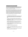
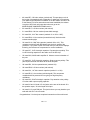
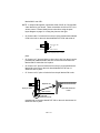
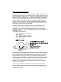
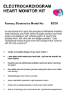
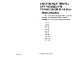
NOTE: In steps 84 through 88, connections CCW, SW-B, W, CW and SWA are labeled on your board. These connections all refer to POT1, the
volume control. Please identify these connections using the parts
layout diagram on page 21 or using the picture at the right.
r
84. Connect the 2" of red wire from the pin of the potentiometer labeled
CCW to the hole on the main board labeled POT-CCW and solder in
Wire ju mper JMPA
Display PC board
Main PC board
(not all components show n f or clarity
place.
r
85. Connect a 7" piece of white (or other color) wire from the pin on the
potentiometer labeled SW-B to the hole on the main board near VR1
labeled SW-B. Solder the wire in place.
r
86. Connect a 5" piece of black wire from the pin on the potentiometer
labeled W to the hole on the main board labeled POT-W near J1.
Solder the wire in place.
r
87. Connect a 5½" piece of red wire from the pin labeled CW on the
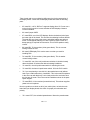
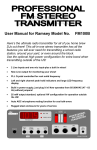
Magnified view
Display PC board
Main PC board
Solder fillet between PC
boards
Solder fillet
between PC boards
potentiometer to the hole labeled POT-CW on the main board near U4.
Solder the wire in place.
CB-1 • 15
r
88. Connect a 7" piece of black wire from the pin labeled SW-A on the
potentiometer to the hole labeled SW-A on the main board near VR1.
Solder the wire in place.
Finally! You've just completed the assembly of your CB-1 and now you're
almost ready for a test run. First go over all connections and wiring to check
for any mistakes. You sure wouldn't want to try out your kit in a hurry and
damage something that may not be easy to repair. Chatterboxes have
feelings too!
INITIAL TESTING
To begin our initial tests, we need only a few missing pieces to complete the
whole voice recorder system.
• A good 12VDC source such as a battery or a regulated supply.
• Suitable connectors for power, speaker, mike, and radio interface.
• A speaker or radio.
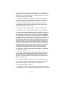
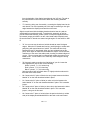
r
1. Verify that all parts are mounted and
soldered in the correct places.
r
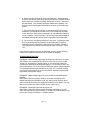
2. Make sure the power switch is turned off.
Plug in the 12VDC supply to J4. Make sure
the center pin is the positive terminal, and
the outside of the jack is ground or
negative.
TA B
r
3. Plug your speaker into J2.
r
4. Turn on the voice recorder and watch closely for any problems. For
example, if you turn it on and the displays do not turn on, turn it back off
again and check your connections. If only one display comes on, or does
odd things, do the same. If both displays come on, most likely all is fine to
continue testing.
r
5. Press the mode switch (S1) a few times to see if the first LED display
(DS2) counts from 1 to 7 and back to 1 again. Then press the address
switch (S2 to see if the second LED display (DS1) counts from 1 to 5 and
back to 1 again. Depress each switch until the mode and address LEDs
show "1 1" and press the start button; some random noise may be
audible at the speaker, but since nothing has been recorded yet, there
should be no sound.
FRONT
CB-1 • 16
r
6. Switch the voice recorder to mode 6 and address 1. Press and hold
down the start button while talking into the microphone. Release the start
button when you are done recording. Switch back to mode 1 and press
the start button. Your message should be audible at the speaker. The
decimal points of the displays should light as long as you hold the start
button.
r
7. If the preceding step worked fine, try the same thing for all memory
addresses; you should have a total of five, four second long recording
areas. When you have saved a message in all five addresses, switch to
mode 4, address 1 and press start. The unit should now play through all
messages and keep the decimal point lit regardless of the start button.
r
8. You're all set if everything worked up to this point. Try playing around
a bit to get familiar with the operation of this kit and how a couple of
addresses can be combined to extend the time of a single message. A
lot of transistors are at work in this kit and we hope you enjoy it. Have
fun!
If any of these steps did not work as described, go to the trouble-shooting
section of the manual to determine how to resolve the problem.
TROUBLESHOOTING TIPS
PROBLEM: Neither display lights when powered up, and there is no sound.
SOLUTION: Use a multimeter and check to make sure you have 12VDC
across C15, and that it is of proper polarity. If not, correct the problem by
reversing the connections to the power supply. If it is OK check to see if you
have 5 volts across C16. If not, check to make sure that the voltage regulator
is in the proper direction (it's probably hot by now). If it is oriented correctly,
turn off power and recheck all of your connections, especially anything that
might short out the power supply.
PROBLEM: Neither display lights, but some sound is heard when start is
pressed.
SOLUTION: Most everything is working. Just check everything on the
display board and the orientation of Q6, Q5, and Q4. Also check for good
solder connections between the display board and the main board. You may
also check to make sure there is 5VDC on pins 3 and 4 of U1.
PROBLEM: One display lights the other does not.
SOLUTION: Check the microprocessor for proper orientation. If it is OK
check C10 and R24 for proper insertion. If you have an oscilloscope you can
look on pin 15 and 16 for about a 1-2 Mhz waveform.
CB-1 • 17
PROBLEM: A segment or two is out on one or both displays, or odd
numbers are displayed.
SOLUTION: These problems most often occur right behind the displays,
where solder bridges and cold solder joints form. Don’t worry; even some
experienced solderers still have trouble with these.
PROBLEM: Decimal point is always on.
SOLUTION: Either there is something wrong with your keying detection
circuit or you have a resistive load plugged into the mike in jack, such as the
speaker in the wrong jack or a regular mike plugged into the jack. If you want
to use your own regular mike, connect a .1uF ceramic capacitor in line with
the mike. This blocks the DC path through the mike but allows audio to pass.
PROBLEM: One or more switches won't work, but everything else is OK.
SOLUTION: Check the junction between your main board and the display
board. Many problems can arise here.
USING YOUR CB-1 VOICE RECORDER KIT:
Once the kit is assembled and tested, it’s very simple to use:
To select a mode: Press the mode switch repeatedly until the display reads
the mode you want.
To select an address: Press the address switch repeatedly until the display
reads the appropriate address.
To record a message: Select mode six, then select any one of the five
addresses. Press the play button and talk into the mike. Release the play
button when you are finished recording.
To playback a message: Select any of the modes 1-5 and any previously
recorded address, and press the play button. The voice recorder will then
play a message according to which mode is selected.
CB-1 • 18
CB-1 • 19
MICROPHONE CONSIDERATIONS
The CB-1 has a built-in miniature electret condenser microphone which is ideal
for stand alone operation. If you would like to use an external microphone, it can
be connected to the "MIC IN" jack, J3. Any sort of microphone may be used. In
addition, the CB-1 is designed to be used with push-to-talk (PTT) microphones
of the Icom/Yaesu/Radio Shack variety. If one of these microphones is used,
you may use the PTT button on the mike to automatically start and stop the
recorder. In this case, the CB-1 will record anytime the microphone button is
depressed. Simply pressing the start button will repeat that message over the
radio. The CB-1 will even key the radio itself!
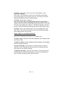
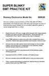
We have included the pin out diagram for the 5 pin DIN connector below.
Information may be found about the proper wiring to your radio from your
manufacturer or from the manual that came with your radio. To hook up the
chatterbox to your radio, you must understand the pins of the DIN connector on
the rear of the unit:
5 Pin DIN Jack Connections:
Pin 1: Audio output to radio mic in
Pin 2: Ground
Pin 3: Push to talk (open collector)
Pin 4: Radio speaker to chatterbox.
Pin 5: No connection
Icom style radios "look" for the closure of the microphone's push-to-talk switch
by sensing current being drawn by the microphone. Circuitry inside the radio (or
CB-1) senses the current draw by this resistor and in turn keys the radio. You
must be aware that if you try to connect a microphone that does not have a
resistance greater than 10K ohms to the CB-1's microphone input jack, J3, the
CB-1 will trigger the transmitter. Putting a switch in series with the mike will act
as a PTT button or if you wish to use the front panel Start button, add a
capacitor (.1uF ) in series with the microphone so the CB-1 will not see any
current drawn by the mike.
Due to the myriad of different radios and microphones, we're sorry that we
cannot provide exact, precise, tested hook-up instructions for each and every
radio. Here's a great place to use your radio skill and common sense to solve a
typical hook up project!
CB-1 • 20
CB-1 PARTS LAYOUT DIAGRAM
CB-1 • 21
The Ramsey Kit Warranty
Please read carefully BEFORE calling or writing in about your kit. Most problems can be
solved without contacting the factory.
Notice that this is not a "fine print" warranty. We want you to understand your rights and ours too! All Ramsey
kits will work if assembled properly. The very fact that your kit includes this new manual is your assurance that
a team of knowledgeable people have field-tested several "copies" of this kit straight from the Ramsey
Inventory. If you need help, please read through your manual carefully, all information required to properly
build and test your kit is contained within the pages!
1. DEFECTIVE PARTS: It's always easy to blame a part for a problem in your kit, Before you conclude that a
part may be bad, thoroughly check your work. Today's semiconductors and passive components have
reached incredibly high reliability levels, and its sad to say that our human construction skills have not! But on
rare occasions a sour component can slip through. All our kit parts carry the Ramsey Electronics Warranty
that they are free from defects for a full ninety (90) days from the date of purchase. Defective parts will be
replaced promptly at our expense. If you suspect any part to be defective, please mail it to our factory for
testing and replacement. Please send only the defective part(s), not the entire kit. The part(s) MUST be
returned to us in suitable condition for testing. Please be aware that testing can usually determine if the part
was truly defective or damaged by assembly or usage. Don't be afraid of telling us that you 'blew-it', we're all
human and in most cases, replacement parts are very reasonably priced.
2. MISSING PARTS: Before assuming a part value is incorrect, check the parts listing carefully to see if it is a
critical value such as a specific coil or IC, or whether a RANGE of values is suitable (such as "100 to 500 uF").
Often times, common sense will solve a mysterious missing part problem. If you're missing five 10K ohm
resistors and received five extra 1K resistors, you can pretty much be assured that the '1K ohm' resistors are
actually the 'missing' 10 K parts ("Hum-m-m, I guess the 'red' band really does look orange!") Ramsey
Electronics project kits are packed with pride in the USA. If you believe we packed an incorrect part or omitted
a part clearly indicated in your assembly manual as supplied with the basic kit by Ramsey, please write or call
us with information on the part you need and proof of kit purchase
3. FACTORY REPAIR OF ASSEMBLED KITS:
To qualify for Ramsey Electronics factory repair, kits MUST:
1. NOT be assembled with acid core solder or flux.
2. NOT be modified in any manner.
3. BE returned in fully-assembled form, not partially assembled.
4. BE accompanied by the proper repair fee. No repair will be undertaken until we have received the
MINIMUM repair fee (1/2 hour labor) of $18.00, or authorization to charge it to your credit card
account.
5. INCLUDE a description of the problem and legible return address. DO NOT send a separate letter; include
all correspondence with the unit. Please do not include your own hardware such as non-Ramsey
cabinets, knobs, cables, external battery packs and the like. Ramsey Electronics, Inc., reserves the
right to refuse repair on ANY item in which we find excessive problems or damage due to
construction methods. To assist customers in such situations, Ramsey Electronics, Inc., reserves
the right to solve their needs on a case-by-case basis.
The repair is $36.00 per hour, regardless of the cost of the kit. Please understand that our technicians are not
volunteers and that set-up, testing, diagnosis, repair and repacking and paperwork can take nearly an hour of
paid employee time on even a simple kit. Of course, if we find that a part was defective in manufacture, there
will be no charge to repair your kit (But please realize that our technicians know the difference between a
defective part and parts burned out or damaged through improper use or assembly).
4. REFUNDS: You are given ten (10) days to examine our products. If you are not satisfied, you may return
your unassembled kit with all the parts and instructions and proof of purchase to the factory for a full refund.
The return package should be packed securely. Insurance is recommended. Please do not cause needless
delays, read all information carefully.
CB-1 • 22
CB-1 "CHATTERBOX" VOICE RECORDER
Quick Reference Page Guide
Introduction to the CB-1 ...................
How it works .....................................
Parts list ............................................
CB-1 Assembly instructions..............
Initial testing......................................
Troubleshooting ................................
Using the CB-1 .................................
Microphone considerations ..............
Parts Layout diagram .......................
Schematic diagram ...........................
REQUIRED TOOLS
• Soldering Iron (Radio Shack #RS64-2072)
• Thin Rosin Core Solder (RS64-025)
• Needle Nose Pliers (RS64-1844)
• Small Diagonal Cutters (RS64-1845)
• <OR> Complete Soldering Tool Set
(RS64-2801)
ADDITIONAL SUGGESTED ITEMS
• Soldering Iron Holder/Cleaner (RS-64-
Price: $5.00
Ramsey Publication No. MCB-1
Assembly and Instruction manual for:
RAMSEY MODEL NO. CB-1
RAMSEY ELECTRONICS, INC.
793 Canning Parkway
Victor, New York 14564
Phone (716) 924-4560
Fax (716) 924-4555
CB-1 • 23
4
5
7
8
17
18
19
20
21
22
TOTAL SOLDER POINTS
293
ESTIMATED ASSEMBLY
TIME
Beginner ...............8.8
hrs
Intermediate .........5 hrs
Advanced .............3.8
hrs