1
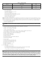
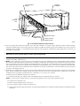
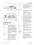
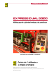
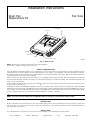
Installation Instructions
Drain Pan
Replacement Kit
Fan Coils
CONDENSATE PAN
DOOR ASSY
SUPPORT
SUPPORT COIL (2)
TAPE
WRAP WITH KRAFT PAPER
A03095
→ Fig. 1—Drain Pan Kit
NOTE: Read the entire instruction manual before starting the installation.
This symbol → indicates a change since the last issue.
SAFETY CONSIDERATIONS
Improper installation, adjustment, alteration, service, maintenance, or use can cause explosion, fire, electrical shock, or other conditions which may
cause personal injury or property damage. Consult a qualified installer, service agency, or your distributor or branch for information or assistance.
The qualified installer or agency must use factory-authorized kits or accessories when modifying this product. Refer to the individual instructions
packaged with the kits or accessories when installing.
Follow all safety codes. Wear safety glasses and work gloves. Use quenching cloth for brazing operations. Have fire extinguisher available. Read
these instructions thoroughly and follow all warnings or cautions attached to the unit. Consult local building codes and National Electrical Code
(NEC) for special requirements.
. When you see this symbol on the unit and in instructions or manuals, be alert
Recognize safety information. This is the safety-alert symbol
to the potential for personal injury.
Understand the signal words DANGER, WARNING, CAUTION, and NOTE. These words are used with the safety-alert symbol. DANGER
identifies the most serious hazards which will result in severe personal injury or death. WARNING signifies hazards which could result in personal
injury or death. CAUTION is used to identify unsafe practices which would result in minor personal injury or product and property damage. NOTE
is used to highlight suggestions which will result in enhanced installation, reliability, or operation.
WARNING: Before installing or servicing unit, always turn off all power to unit. There may be more than 1 disconnect
switch. Turn off accessory heater power if applicable. Electrical shock can cause personal injury or death.
INTRODUCTION
With the introduction of the new drain pan for fan coils produced starting January 1996, applicable kits have been designed for replacement
purposes for older fan coils. (See Fig. 1.) The kits contain a new generation pan, 2 coil supports, and fitting door which accommodates the new
pan configuration. (See Table 1.)
INSTALLATION
If it is determined that the system does not have leaks, and the refrigerant is not contaminated, proceed as follows:
Form:
IM-FA4A-12
Cancels:
IM-FA4A-07
Printed in U.S.A.
6-03
Catalog No.
63FA-4A8
→ Table 1—Drain Pan Usage
KIT
PART NO.
328140-751
328140-752
328140-753
FAN COIL
APPLICATION
FA4, FB4, FC4, FH4, FX4, 40YA, 40YR, 617A, 618A
FA4, FB4, FC4, FH4, FX4, 40YR, 617A,
FK4
FA4, FB4, FC4, FE4, FH4, FV4, FX4
FK4
COIL
SIZE
018, 024
030, 036
001
042
003
1. Recover system refrigerant.
a. Attach gage/manifold set to service valves.
b. Start unit in cooling mode.
c. Front seat (close) liquid line service valve.
d. Operate unit until vapor pressure reaches 5 psig (35kPa).
e. Turn off electrical supply to outdoor unit.
f. Front seat (close) vapor service valve.
g. Recover any remaining refrigerant.
NOTE: All condenser coils hold only a factory-supplied amount of refrigerant. Excess refrigerant, such as in long-line applications, may cause
compressor internal pressure relief valve to open (indicated by sudden rise in vapor pressure) before vapor pressure reaches 5 psig (35kPa). If this
occurs, turn off electrical supply to outdoor unit immediately, front seat (close) vapor service valve, and recover any remaining refrigerant.
2. Turn off electrical supply to indoor unit.
3. Disconnect condensate drain line.
WARNING: Do not use torch to remove components. Oil may catch fire causing personal injury or death. Use tubing
cutter.
4. Disconnect liquid and vapor lines from indoor coil (use a tubing cutter to cut the lines).
5. Remove coil access blower and fitting panels.
6. Remove 1 screw securing coil to unit casing.
7. Remove coil/pan assembly from unit.
8. Place assembly on a flat surface. Remove 2 screws securing coil support columns to pan. (See Fig. 2.)
9. Rotate columns 90°, pull away from coil, and remove columns from assembly.
10. Remove remaining 2 screws securing coil to condensate pan.
11. Remove coil from condensate pan.
12. Discard old drain pan and supports
13. Remove kit from carton.
14. Snap metal pan support (ski) into bottom of drain pan.
15. Slide coil into pan assemble.
16. Snap in supports.
17. Secure coil to pan with 2 sheet metal screws.
18. Re-install coil/pan assembly into unit casing.
19. Secure with 1 screw into unit casing.
20. Install new fitting panel.
21. Replace coil access blower panels.
→
22. Connect drains.
a. Cap openings must be removed.
b. Use a knife to start the opening near the tab and, using pliers, pull the tab to remove the disk.
c. Clean the edge of the opening if necessary and install the condensate line.
d. Caulk around the lines where they exit the fitting to retain the low leak rating of the unit.
→
CAUTION: The conversion of the fan coil to downflow requires special procedures for the condensate drains on both
A-coil and Slope units. The vertical drains have an overflow hole between the primary and secondary drain holes. This hole
is plugged for all applications except downflow, but must be used for downflow. During the conversion process, remove the
plastic cap covering the vertical drains only and discard. Remove the plug from the overlow hole and discard. At completion
of the downflow installation, caulk around the vertical pan fitting to door joint to retain the low air leak performance of the
unit. Failure to follow this CAUTION could result in minor personal injury or product and property damage.
—2—
BLOWER
ASSEMBLY
COIL MOUNTING
SCREW
COIL
SUPPORT
RAIL
SLOPE COIL
SKI
DRAINPAN
REFRIGERANT
CONNECTIONS
PRIMARY DRAIN
OVERFLOW HOLE
SECONDARY DRAIN
A95288
Fig. 2—Horizontal Installation of Drain Pan Kit
→ Units
are equipped with primary and secondary 3/4-in. FPT drain connections. To prevent property damage and achieve optimum drainage
performance, BOTH primary and secondary drain lines should be installed and include properly sized condensate traps. Factory approved
condensate traps are available. It is recommended that PVC fittings be used on the plastic condensate pan. Finger-tighten plus 1-1/2 turns. Do not
over-tighten. Use Pipe dope.
→
CAUTION: Shallow, running traps are inadequate and DO NOT allow proper drainage. Failure to follow this CAUTION
could result in minor personal injury or product and property damage.
→ NOTE:
When connecting condensate drain lines, avoid blocking filter access panel, thus preventing filter removal. After connection, prime both
primary and secondary condensate traps.
→ NOTE: If unit is located in or above a living space where damage may result from condensate overflow, a field-supplied, external condensate
pan should be installed underneath the entire unit, and a secondary, condensate line (with appropriate trap) should be run from the unit into the
pan. Any condensate in the external condensate pan should be drained to a noticeable place. As an alternative to using an external condensate pan,
some localities may allow the use of a separate 3/4-inch cndensate line (with appropriate trap) to a place where the condensate will be noticeable.
The owner of the structure must be informed that when condensate flows from the secondary drain or external condensate pan, the unit requires
servicing or water damage will occur.
→ Install traps in the condensate lines as close to the coil as possible. Make sure that the outlet of each trap is below its connection to the condensate
pan to prevent condensate from overflowing the drain pan. Prime all traps, test for leaks, and insulate traps if located above a living area.
Condensate drain lines should be pitched downward at a minimum of 1 in. for every 10 ft. of length.
Consult local codes for additional restricitons or precautions.
23. Reconnect liquid and vapor refrigerant lines and condensate drain line. Install filter drier(s) if necessary.
NOTE: If a torch is used to unbraze the line set, protect the fitting panel with a wet cloth or braze shield as necessary.
24. Evacuate line set and indoor coil.
25. Back seat (open) liquid and vapor service valves.
26. Turn on electrical supplies to indoor and outdoor units.
27. Check system refrigerant charge and operation. See Split-System Residential Air Conditioners and Heat Pump Service Manual for further
information.
—3—
4
SERVICE TRAINING
Packaged Service Training programs are an excellent way to increase your
knowledge of the equipment discussed in this manual, including:
• Unit Familiarization • Maintenance
• Installation Overview • Operating Sequence
A large selection of product, theory, and skills programs is available, using popular
video-based formats and materials. All include video and/or slides, plus companion
book.
Classroom Service Training plus "hands-on" the products in our labs can mean
increased confidence that really pays dividends in faster troubleshooting, fewer
callbacks. Course descriptions and schedules are in our catalog.
CALL FOR FREE CATALOG 1-800-644-5544
[ ] Packaged Service Training [ ] Classroom Service Training
A94328
© 2003 CAC/BDP
7310 W. Morris St., Indianapolis, IN 46231
imfa4a12 —4—
Book/Tab: 1/3d, 4/2e
Catalog No. 63FA-4A8