1
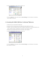
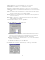
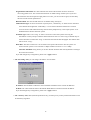
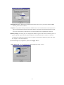
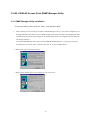
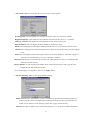
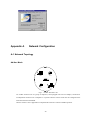
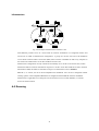
AmbiCom WL1100B-AP Wireless LAN Access Point
User Manual
Version 1.50
Oct. 1, 2001
Federal Communications Commission Statement
This device complies with FCC Rules Part 15. Operation is subject to the following two conditions:
This device may not cause harmful interference.
This device must accept any interference received, including interference that may cause undesired operation.
This equipment has been tested and found to comply with the limits for a Class B digital device, pursuant to Part
15 of the FCC Rules. These limits are designed to provide reasonable protection against harmful interference in
a residential installation. This equipment generates, uses and can radiate radio frequency energy. If this
equipment is not installed and used in accordance with the manufacturer's instructions, it may cause harmful
interference to radio communications. However, there is no guarantee that interference will not occur in a
particular installation. If this equipment does cause harmful interference to radio or television reception, which
can be determined by during the equipment off and on, the user is encouraged to try to correct the interference by
one or more of the following measures:
Reorient or relocate the receiving antenna.
Increase the separation between the equipment and receiver.
Connect the equipment to an outlet on a circuit different from that to which the receiver is connected.
Consult the dealer or an experienced radio/TV technician for help.
The use of shielded cables for connection of the monitor to the graphics card is required to assure compliance
with FCC regulations. Changes or modifications to this unit not expressly approved by the party responsible for
compliance could void the user's authority to operate this equipment.
Manufacturer's Disclaimer Statement
The information in this document is subject to change without notice and does not represent a commitment on the
part of the vendor. No warranty or representation, either expressed or implied, is made with respect to the
quality, accuracy or fitness for any particular purpose of this document. The manufacturer reserves the right to
make changes to the content of this document and/or the products associated with it at any time without obligation
to notify any person or organization of such changes. In no event will the manufacturer be liable for direct,
indirect, special, incidental or consequential damages arising out of the use or inability to use this product or
documentation, even if advised of the possibility of such damages. This document contains materials protected
by copyright. All rights are reserved. No part of this manual may be reproduced or transmitted in any form, by
any means or for any purpose without expressed written consent of its authors. Product names appearing in this
document are mentioned for identification purchases only. All trademarks, product names or brand names
appearing in this document are registered property of their respective owners.
Contents
SECTION 1 ABOUT WL1100B-AP ACCESS POINT.................................2
INTRODUCTION ..........................................................................................................................................2
1-1 FEATURES ............................................................................................................................................2
1-2 FIRMWARE FUNCTIONALITY ........................................................................................................2
1-3 APPLICATIONS ....................................................................................................................................3
1-4 PRODUCT KIT .....................................................................................................................................3
SECTION 2 HARDWARE INSTALLATION......................................................5
2-1 EQUIPMENT REQUIREMENT .........................................................................................................5
2-2 WL1100B-AP HARDWARE INSTALLATION ..........................................................................5
2-3 SOFTWARE LIMITATION..................................................................................................................5
SECTION 3 CONFIGURING WL1100B-AP ACCESS POINT..........6
3-1 INSTALLING USB DRIVER FOR ACCESS POINT ...................................................................6
3-1-1 INSTALLING WL1100B-AP USB DRIVER FOR WINDOWS® 98..................................................6
3-1-2 INSTALLING WL1100B-AP USB DRIVER FOR WINDOWS® 2000 .............................................7
3-1-3 INSTALLING WL1100B-AP USB DRIVER FOR WINDOWS® MILLENNIUM...............................9
3-2
WL1100B-AP ACCESS POINT DFU UTILITY ..............................................................10
3-2-1 DFU (USB Configuration Utility) Utility Installation..........................................................................10
3-2-2 DFU (USB Configuration Utility) Utility Configuration ...................................................................... 11
3-3 WL1100B-AP ACCESS POINT SNMP MANAGER UTILITY.........................................15
3-3-1 SNMP Manager Utility Installation.....................................................................................................15
3-3-2 SNMP Manager Utility Configuration.................................................................................................16
APPENDIX A NETWORK CONFIGURATION............................................20
A-1 NETWORK TOPOLOGY .................................................................................................................20
Ad-Hoc Mode ..............................................................................................................................................20
Infrastructure ..............................................................................................................................................21
A-2 ROAMING ..........................................................................................................................................21
APPENDIX B SPECIFICATIONS...............................................................................23
APPENDIX C
GLOSSARY ................................................................................................24
1
Section 1
About WL1100B-AP Access Point
Introduction
The WL1100B-AP (11 Mbps WLAN Access Point) is a long-range, high performance LAN product,
which provides Access Point services to a 2,4 GHz RF network and bridges to an Ethernet backbone. The
design of this product is based on AT76C510 (bridge-on-a-chip) module, a highly integrated ASIC designed
to combine legacy LANs with wireless LANs. AT76C510 performs all the necessary inter-networking and
bridging functions. It receives data from both networks, stores them locally for further processing, installs and
maintains connections and transmits the packets to the proper destination. Furthermore, AT76C510 interfaces
three more modules, the Ethernet PHY, the wireless PHY and the RAM modules, for allowing compact
system implementation and flexibility for supporting almost all the possible physical interfaces.
1-1 Features
– Intersil PRISMI, PRISMII Direct Sequence Spread Spectrum (DSSS) radio chip set, able to
communicate also with other DSSS radios
– Supports 11 Mbps rates with automatic fallback to 5.5, 2 and 1 Mbps
– WEP encryption/decryption is accomplished on the fly
– Ethernet MAC supports MII interface and 10/100Mbit speeds
– Hardware modules for Packet Filtering and statistics gathering
– SRAM, Flash interface for data buffering and program storage, supporting up to 16 MB of memory
– Integrated 2 x 6K x 32 bit internal SRAM modules for fast 32-bit program execution and temporary
storage of data
– 128-pin PQFP, TQFP
– JTAG Boundary Scan (IEEE 1149.1) test access port for board-level production test
1-2 Firmware functionality
The firmware functionality of the bridge supports:
1. Distributed Coordination Function (DCF)
CSMA/CA
Backoff procedure
NAV management
ACK procedure
2
Retransmission of unacknowledged frames
2. RTS/CTS handshake
3. Duplicate detection and recovery
4. Fragmentation and Reassembly
5. Beacon generation
6. Probe response
7. Wired Equivalent Privacy Algorithm (WEP)
8. Authentication Algorithm (Open System, Shared Key)
1-3 Applications
The Serial of LAN products offer a fast, reliable, cost-effective solution, allowing clients to wirelessly
access the network in applications such as following:
1. Remote access to corporate network information
E-mail, file transfer and terminal emulation
2. Difficult-to-wire environments
Historical or old buildings, asbestos installations, and open area where wiring is difficult to employ
3. Frequently changing environments
Retailers, manufacturers and banks who frequently rearrange the workplace and change location
4. Temporary LANs for special projects or peak time
Trade shows, exhibitions and construction sites need temporary setup for a short time period. Retailers,
airlines and shipping companies need additional workstations for a peak period. Auditors require
workgroups at customer sites.
5. Access to database for mobile workers
Doctors, nurses, retailers, white-collar workers need access to database while being mobile in the hospital,
retail store or office campus.
6. SOHO (Small Office and Home Office) users
SOHO users need easy and quick installation of a small computer network.
1-4 Product Kit
u
WL1100B-AP ……………………………………………………….x 1
u
Antenna (fixed)………………………………………………………x 2
u
WL1100B-AP utility CD……………………………….……...…….x 1
u
A/C Power Adapter………………………………………………….x 1
3
u
USB cable…………………………………………………………….x 1
If any of the listed items are not included or found damaged, please contact your local dealer .
4
Section 2
Hardware Installation
2-1 Equipment Requirement
Installation of WL1100B-AP requires:
1. An A/C power outlet (100~240V,50~60Hz) which supply the power for the WL1100B-AP Access Point
2. A 10/100 Base-T (UTP) Ethernet cable drop (RJ-45 connector)
2-2 WL1100B-AP Hardware Installation
Please follow these procedures while setting up the hardware:
1. Site Selection
Choose a proper place for your WL1100B-AP.
In general, the best location to place your WL1100B-AP is the center of your wireless coverage, with line
of sight to all your mobile stations.
2. Adjust the direction of the Antenna
Adjust the direction of the antenna placement to improve the WL1100B-AP’s performance. Try to place the
antenna in the position that it can best cover its BSS. Normally, the higher you place the antenna, the better
the performance will be. The character of diversity enhances the receiving sensitivity.
3. Connect the Ethernet Cable
WL1100B-AP can be connected to the 10Base-T Ethernet network. Connect your UTP Ethernet cable to the
RJ-45 connector of the WL1100B-AP AP and connect the other side of UTP Ethernet cable to a hub.
4. Connect the Power Cable
Connect the power adapter cable to the DC5V Power Socket of the WL1100B-AP. ONLY use the power
adapter supplied with the WL1100B-AP. Otherwise, the product may be damaged.
2-3 Software Limitation
1.
DFU Software
Operation System:
English Windows 98/2000/ME, Chinese Windows 98/2000/ME
2.
SNMP Software
Operation System:
English Windows 98/NT/ME
5
Section 3
Configuring WL1100B-AP Access Point
3-1 Installing USB Driver For Access Point
The Wireless Network Access Point WL1100B-AP can be configured by DFU utility for Windows®
98/2000/ME. You need plug the USB cable with the WL1100B-AP and the USB slot of the PC to run
DFU.exe for configuring the WL1100B-AP and setting the setup.
3-1-1 Installing WL1100B-AP USB Driver For Windows® 98
1. Please boot your PC into Windows® 98.
2. Install WL1100B-AP software (the DFU utility) from Installation CD selection.
3. Ensure you have followed the procedure as described in the previous section to finish hardware installation.
4. Plug the two sides of the USB cable into the USB slots of WL1100B-AP and your PC.
5. Windows® 98 will automatically detect the WL1100B-AP and prompt you to install the necessary driver.
Please make sure that the Setup Utility CD is inserted into your CD ROM and click “Next” to begin the
installation.
6. Select “Search for the best driver…” and click “Next”.
6
7. Select “Specify a location” and click “Browse”. On the windows information dialog, double-click the
“D:\WL1100B-AP\USB_DRIVER” folder icon from the list and Windows® 98 will automatically enter the
path. Then click “Next”.
8. Windows® 98 will then acknowledge that it has found the appropriate driver and click "Next".
9. Windows® 98 will install the driver “Access Point USB Device Driver”. As the driver files are being
copied to the appropriate location, you will be prompted to insert the Windows® 98 CD.
NOTE: You must insert the Windows ® 98 CD as the driver installation requires special files that will not be
available, even if you have stored a copy of Windows ® 98 source on your hard drive.
10.
After Windows® 98 has finished installing the appropriate files, click “Finish”.
11.
From the Control Panel, double-click the “System” icon.
12.
From the “Hardware” menu, please select the “Device Manager” tab. And check the “AccessPoint”
device whether it works fine.
3-1-2 Installing WL1100B-AP USB Driver For Windows® 2000
1. Please boot your PC into Windows® 2000.
2. Plug the two sides of the USB cable into the USB slots of WL1100B-AP and your PC.
3. Windows® 2000 will automatically detect the WL1100B-AP and prompt you to install the necessary driver.
Make sure that the Setup Utility CD is inserted in the CD-Rom drive and click “Next” on the Found New
Hardware Wizard screen to proceed.
7
4. Select “Search for a suitable driver..” and click “Next” to search for the Windows® 2000 driver.
5. In “Optional Search Location”, Select “CD-ROM Drive” and click “Next”.
6. Please browse the file as shown in the dialog box, then click “OK”.
7. Windows® 2000 is now ready to install the driver. Click “Next” to continue. After Windows® 2000 has
finished installing the appropriate files, click “Finish”.
8
8. From the Control Panel, double-click the “System” icon.
9. From the “Hardware” menu, please select the “Device Manager” tab. And check the “AccessPoint”
device whether it works fine.
3-1-3 Installing WL1100B-AP USB Driver For Windows® Millennium
1. Please boot your PC into Windows® Millennium.
2. Plug the two sides of the USB cable into the USB slots of WL1100B-AP and your PC.
3. Windows® ME will automatically detect the WL1100B-AP and prompt you to install the necessary driver.
Select “Install the software Automatically” and click the “Next” button to continue.
4. Windows will now install the driver files. Click “Finish” when completed.
5. From the Control Panel, double-click the “System” icon.
6. From the “Hardware” menu, please select the “Device Manager” tab. And check the “AccessPoint”
device whether it works fine.
9
3-2 WL1100B-AP Access Point DFU Utility
3-2-1 DFU (USB Configuration Utility) Utility Installation
To setup the utility, please click the “Start” icon and then “Run”.
1. Install the DFU utility by clicking on “INSTALL WL1100B-AP” from auto-run CD menu selection. Or
type “D:\WL1100B-AP\USB\Setup.exe.” or use browse the file in the dialog box. Then click “OK” to
start the setup. (PS: D: is your CD-ROM driver)
2. Please click “Next” for further running.
.
3. Please browse the file shown in the dialog box, then click “Next”
.
4. Setup will add program icon to the program folder shown as blow, then click “Next” for further setup.
10
.
5. After the installation of utility, please click “Finish”.
3-2-2 DFU (USB Configuration Utility) Utility Configuration
1. Click “Start” then, “Program” folder, you will find icon, please press icon “DFU” to execute program.
Click “Basic Setting” “Advanced” “IP Setting” “WEP” “About” Tab to change other function.
2. The “Status” Tab, it will show the Wireless Network Access Point current status.
Working Status: This will display the connection situation to notify any connection problem.
Regulation Domain: It will display the current domain operated with FCC from 1 to 11 channels.
11
Firmware Version: It will display the current firmware version of this Access Point.
Ethernet Address: This will display the MAC ID address of the Access Point.
ESSID: This will display the name that is shared with all the stations in your wireless network system.
Channel: This will display the current working channel in which the AP and the with it associated stations
work.
WEP: This will display the status of encryption protocol. It will read “Disabled”, if the WEP encryption
protocol is not enabled. When it is in use, it will show “Enabled”.
Reconnect: This button is to be clicked for reconnect AP, if the connection is broken. The parameter date
will be re-read and retrieved.
Restore Default: To click this button the default values will be restored and any setting you may have
changed thru the DFU utility will be lost.
If you had changed any configuration, please click “Apply” Button.
3. The “Basic Setting” Tab, you can change ESSID, Channel.
ESSID: ESS stands for “Extended Service Set”. The ESS ID is the name shared among all points in a
wireless network system. The ESSID must be identical for all points in the system and must not
exceed over 30 characters. After changing, please click “Apply” button for setup.
Channel: The value of channel can be selected from channel 1 to 11 for the FCC domain and between
channels 1 to 13 for ETSI domain.
If you had changed any configuration, please click “Apply” Button.
4. The “Advanced” Tab, you can change “Authentication Type” “Preamble Type” and “Basic Rate”.
12
Fragmentation Threshold: The value indicates how much of the network resources devoted to
recovering packet errors. The value should remain at its default setting of 2432 bytes. If you have
decreased this value and experience high packet error rates, you can increase it again, but will likely
decrease overall network performance.
RTS Threshold: The value should remain on its default setting 2432 bytes.
Authentication Type: It can be selected for “Open System”, “Shared Key” or “Both” for the indication
of an authentication algorithm. “Shared Key” is to be selected while the WEP for PC card and
Access Point are both enabled and setup with the same passphrase key. And “Open System” is for
disabled WEP in Wireless Network system.
Preamble Type: There is the “Long” or “Short” selection to ensure that systems receiving the
information correctly interpret when the data transmission starts. To select “long” Preamble may be
used to minimize overhead and “Long” to maximize the network data throughput. The default value
will be set for “Long”.
Basic Rate: The basic transfer rate is to set based on the speed of the wireless network system. For
slower network system is to be selected 1-2 Mbps and faster network 1-2-5.5-11 Mbps.
Auto Rate Fall Back setting allows you to have flexible automatic data rate adjustment according to
the connection situation.
If you had changed any configuration, please click “Apply” Button.
5. The “IP Setting” Tab, you can change “IP address” and “IP mask.
IP Address: The IP address of Wireless Network should be different as the network IP addresses.
IP Mask: The value should be same as the Subnet Mask address of wireless Network IP address.
If you had changed any configuration, please click “Apply” Button.
6. The “Security” Tab, WEP (Wired Equivalent Privacy) is a data privacy security mechanism based on a 40
bit shared key algorithm.
13
WEP(ON/OFF): With “Disabled” the WEP function will be not active. If you wish to utilize the WEP
function, please select “Enabled”.
Passphrase: To generate the key, if the WEP is enabled. This is the code used while a wireless point is to
log on to the network thru the WEP encryption function. All points in the Wireless Network system
have to have the same key shared which is set with a maximum of 32 alphanumeric characters.
WEP Key Setting: This setting key is to configure the WEP encryption in the wireless network system. To
generate the key, please insert the same PassPhrase in the field and click the “Done” to create the
encryption key which must be same as the every points on the Wireless Network system. Then Click
the “Apply” to store the setting keys.
If you had changed any configuration, please click “Apply” Button.
7. The “About” Tab, it is the trademark and USB configuration utility version.
14
3-3 WL1100B-AP Access Point SNMP Manager Utility
3-3-1 SNMP Manager Utility Installation
To setup the utility, please click the “Start” icon and then “Run”.
1.
Please note that it’s not necessary to install the “SNMP Manager Utility” if you want to configure the AP
through USB cable only. Before you use SNMP manager utility, make sure that USB configuration utility
is installed, and the AP has been configured. The SNMP utility needs to be configured from the Ethernet,
not through USB port.
To install SNMP Manager Utility, type “D:\WL1100B-AP\SNMP\setup.exe.” or use browse the file in
the dialog box. Then click “OK” to start the setup. (PS: D: is your CD-ROM driver)
2. Please click “Next” for further running.
.
3. Please browse the file shown in the dialog box, then click “Next”
.
15
4. Setup will add program icon to the program folder shown as blow, then click “Next” for further setup.
5. After the installation of utility, please click “Finish”.
3-3-2 SNMP Manager Utility Configuration
1. Click “Start” then, “Program” folder, you will find icon, please press icon “SNMP Configuration Utility:
To execute the program.
2. Please key in “IP Address” for your AP. (Default IP: 192.168.1.250) and click “OK”.
Click “Status” “Basic Setting” “Advanced” “IP Setting” “WEP” “About” Tab to change other function.
16
2. The “Status” Tab, this will display the current wireless connecting status.
Working Status: This will display the connection situation to notify any connection problem.
Regulation Domain: It will display the current domain operated with FCC from 1 to 11 channels.
Firmware Version: It will display the current firmware version of this Access Point.
Ethernet Address: This will display the MAC ID address of the Access Point.
ESSID: This will display the name that is shared with all the stations in your wireless network system.
Channel: This will display the current working channel in which the AP and the with it associated stations
work.
WEP: This will display the status of encryption protocol. It will read “Disabled”, if the WEP encryption
protocol is not enabled. When it is in use, it will show “Enabled”.
Reconnect: This button is to be clicked for reconnect AP, if the connection is broken. The parameter date
will be re-read and retrieved.
Restore Default: To click this button the default values will be restored and any setting you may have
changed thru the DFU utility will be lost.
If you had changed any configuration, please click “Apply” Button.
3. The “Basic Setting” Tab, you can change ESSID, Channel .
ESSID: ESS stands for “Extended Service Set”. The ESS ID is the name shared among all points in a
wireless network system. The ESSID must be identical for all points in the system and must not
exceed over 30 characters. After changing, please click “Apply” button for setup.
Channel: The value of channel can be selected from channel 1 to 11 for the FCC domain and between
17
channels 1 to 13 for ETSI domain.
If you had changed any configuration, please click “Apply” Button.
4. The “Advanced” Tab, you can change “Authentication Type” “Preamble Type” and “Basic Rate”.
Fragmentation Threshold: The value indicates how much of the network resources devoted to
recovering packet errors. The value should remain at its default setting of 2432 bytes. If you have
decreased this value and experience high packet error rates, you can increase it again, but will likely
decrease overall network performance.
RTS Threshold: The value should remain on its default setting 2432 bytes. If you encounter any date
flow, only minor modifications are recommended.
Authentication Type: It can be selected for “Open System”, “Shared Key” or “Both” for the indication
of an authentication algorithm. “Shared Key” is to be selected while the WEP for PC card and
Access Point are both enabled and setup with the same passphrase key. And “Open System” is for
disabled WEP in Wireless Network system.
Preamble Type: There is the “Long” or “Short” selection to ensure that systems receiving the
information correctly interpret when the data transmission starts. To select “long” Preamble may be
used to minimize overhead and “Long” to maximize the network data throughput. The default value
will be set for “Long”.
Basic Rate: The basic transfer rate is to set based on the speed of the wireless network system. For
slower network system is to be selected 1-2 Mbps and faster network 1-2-5.5-11 Mbps.
Auto Rate Fall Back setting allows you to have flexible automatic data rate adjustment according to
the connection situation.
If you had changed any configuration, please click “Apply” Button.
5. The “IP Setting” Tab, you can change “IP address” and “IP mask.
18
IP Address : The IP address of Wireless Network should be different as the network IP addresses.
IP Mask: The value should be same as the Subnet Mask address of wireless Network IP address.
If you had changed any configuration, please click “Apply” Button.
6. The “WEP” Tab, Wired Equivalent Privacy is a data privacy security mechanism based on a 40 bit shared
key algorithm.
WEP(ON/OFF): With “Disabled” the WEP function will be not active. If you wish to utilize the WEP
function, please select “Enabled”.
Passphrase: To generate the key, if the WEP is enabled. This is the code used while a wireless point is to
log on to the network thru the WEP encryption function. All points in the Wireless Network system
have to have the same key shared which is set with a maximum of 32 alphanumeric characters.
WEP Key Setting: This setting key is to configure the WEP encryption in the wireless network system. To
generate the key, please insert the same PassPhrase in the field and click the “Done” to create the
encryption key which must be same as the every points on the Wireless Network system. Then Click
the “Apply” to store the setting keys.
If you had changed any configuration, please click “Apply” Button.
7. The “About” Tab, it is the trademark and USB configuration utility version.
19
Appendix A
Network Configuration
A-1 Network Topology
Ad-Hoc Mode
Notebook
with
GL241101
Desktop PC
with
GL241101
Ad Hoc
Wireless LAN
Notebook
with
GL241101
Desktop PC
with
GL241101
Fig. 1 - Ad-Hoc Wireless LAN
An Ad-Hoc wireless LAN is a group of computers, each equipped with one LAN adapter, connected as
an independent wireless LAN. Computers in a specific Ad-Hoc wireless LAN must be configured at the
same radio channel and ESSID.
Ad-Hoc wireless LAN is applicable at a departmental scale for a branch or SOHO operation.
20
Infrastructure
Desktop PC with ethernet
Desktop PC with ethernet
Sever
Ethernet
Notebook
with
GL241101
Notebook
with
GL241101
GL2411AP-0A
Notebook
with
GL241101
GL2411AP-0A
Desktop PC
with
GL241101
Desktop PC
with
GL241101
Desktop PC
with
GL241101
Infrastructure
Wireless LAN
Infrastructure
Wireless LAN
Fig. 2 An Example of Infrastructure Wireless LAN
WL1100B-AP provides access to a wired LAN for wireless workstations. An integrated wireless and
wired LAN is called an Infrastructure configuration. A group of LAN PC users and a WL1100B-AP
Access Point construct a Basic Service Set (BSS). Each LAN PC in the BSS can talk to any computer in
the wired LAN infrastructure via the WL1100B-AP Access Point.
Infrastructure configuration not only extends the accessibility of a LAN PC to the wired LAN, but also
doubles the effective wireless transmission range for 2 LAN PCs. Since WL1100B-AP is able to forward
data within its BSS, the effective transmission range in an infrastructure LAN is doubled.
BSS ID is, in essence, the ID of each independent WL1100B-AP. All LAN PCs configured without
roaming options in the independent BSS must be configured with the BSS ID of the WL1100B-AP.
Infrastructure is applicable in an enterprise scale for wireless access to central databases, or wireless
access for mobile workers.
A-2 Roaming
21
Desktop PC with ethernet
Desktop PC with ethernet
Sever
Ethernet
Notebook
with
GL241101
Notebook
with
GL241101
GL2411AP-0A
GL2411AP-0A
Roaming
BSS1
Notebook
with
GL241101
Notebook
with
GL241101
BSS2
Desktop PC
with
GL241101
ESS
Fig. 3 Roaming in an Extended Service Set (ESS)
An Infrastructure configuration also supports roaming capability for mobile workers. More than one BSS
can be configured to be an Extended Service Set (ESS). On account of a continuous connection to the
network, users within an ESS can roam freely. All LAN PCs and WL1100B-APs within one ESS must be
configured with the same ESS ID and at the same radio channel.
22
Appendix B
Specifications
WL1100B-AP Access Point
Wired Interface
Ethernet, 10/100 BaseT
Wireless Interface
IEEE 802.11b standard Wireless LAN
Frequency Band
2.412~2.462 GHz (FCC, Canada)
2.412~2.472 GHz (ETSI)
2.412~2.472 GHz (Japan STD-T66)
2.484 GHz (Japan STD-33) (Customized)
RF Technology
Spread Spectrum Direct Sequence
(DSSS)
Channels
FCC : 1-11 channels
ETSI : 1-13 channels
Japan STD-T66 : 1-13 channels
Japan STD-33 : 14 th channel only
23
Appendix C
Access Point ?
Glossary
An internetworking device that seamlessly connects wired and wireless networks.
Ad-Hoc ? An Ad-Hoc wireless LAN is a group of computers each with LAN adapters, connected as an
independent wireless LAN.
Authentication Type ? Indication of an authentication algorithm which can be supported by this node:
1. Open System: Open System authentication is the simplest of the available authentication algorithms.
Essentially it is a null authentication algorithm. Any station that requests authentication with this
algorithm may become authenticated if dot11AuthenticationType at the recipient station is set to Open
System authentication.
2. Shared Key: Shared Key authentication supports authentication of STAs as either a member of those
who know a shared secret key or a member of those who do not.
Open System authentication is the default authentication algorithm.
Backbone ? The core infrastructure of a network. The portion of the network transports information from one
central location to another central location where it is unloaded onto a local system.
Basic Rate ? the data rate of the AP with the value 1,2,5.5 or 11 Mbps for your selection.
Bridge ?
An internetworking function that incorporates the lowest 2 layers of the OSI network protocol model.
BSS ? BSS stands for “Basic Service Set”. It is an Access Point and all the LAN PCs that associated with it.
Channel ? The AP and the with it associated stations will work in this channel. You must set the channel by
consulting Appendix B from violating the Specifications.
DSSS ?
direct sequence spread spectrum
ESS ? ESS stands for “Extended Service Set”. More than one BSS is configured to become Extended Service
Set. LAN mobile users can roam between different BSSs in an ESS.
ESSID ?
In infrastructure association , the stations will link to the AP with the same ESSID as they have.
Ethernet ? A popular local area data communications network, originally developed by Xerox Corp., that
accepts transmission from computers and terminals. Ethernet operates on a 10 Mbps baseband transmission rate,
using a shielded coaxial cable or over shielded twisted pair telephone wire.
Ethernet IP Address and SubMask ?
Please setup them to match your network environment.
For example: If your IP address is 192.168.99.127 and your SubMask is 255.255.255.0. Please set the
IP address of the AP to 192.168.99.xx, which will not have conflict with other IP address
24
and set the SubMask of the AP to 255.255.255.0.
Ethernet Mac Address ?
Infrastructure ?
Don’t change it, as this will disable the AP.
An integrated wireless and wired LAN is called an Infrastructure configuration.
PLCP ?
physical layer convergence protocol
PPDU ?
PLCP protocol data unit
Preamble Type ?
During transmission, the PSDU shall be appended to a PLCP preamble and header to create
the PPDU. Two different preambles and headers are defined : the mandatory supported long preamble and header
which interoperates with the current 1 and 2 Mbps DSSS specification as described in IEEE Std 802.11-1999, and
an optional short preamble and header. At the receiver, the PLCP preamble and header are processed to aid in
demodulation and delivery of the PSDU. The optional short preamble and header is intended for application where
maximum throughput is desired and interoperability with legacy and non-short preamble capable equipment is not
consideration. It is expected to only be used in networks of like equipment that can all handle the optional mode.
(IEEE 802.11b standard)
PSDU ? PLCP service data unit
Roaming ?
network.
A LAN mobile user moves around an ESS and enjoys a continuous connection to the Infrastructure
RTS Threshold ? Transmitters contending for the medium may not be aware of each other. RTS/CTS
mechanism can solve this “ Hidden Node Problem”. If the packet size is smaller than the preset RTS Threshold
size, the RTS/CTS mechanism will NOT be enabled.
WEP ?
Wired Equivalent Privacy (WEP) is an encryption scheme used to protect wireless data communication.
To enable the icon will prevent other stations without the same WEP key from linking with the AP.
25