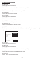
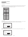
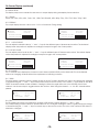
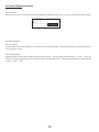
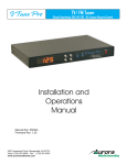
1
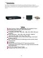
X Tune
Video Processor, Scaler, Switcher,
Integrated TV Tuner
Now has character text generator via rs-232
Installation and
Operations
Manual
Manual Rev: 020901
Firmware Rev: 1.16 and above
205 Commercial Court Morganville, NJ 07751
Voice: (732) 591-5800 Fax: (732) 591-5801
www.auroramultimedia.com
Table of Contents
Product Description ................................1
Warning ................................................. 2
Unpacking ............................................ 2
Installation ............................................. 2
System Overview ................................... 3
Understanding PiP Modes ..................... 3
Remote Control .................................... 4
Front Panel ............................................ 5
On Screen Display (OSD) ....................... 6
Specifications ........................................ 15
Control Port ............................................ 17
RS-232 Protocol ..................................... 17
Connector Specifications ..................... 21
Troubleshooting .................................... 22
Upgrading Firmware ............................. 23
Warranty
............................................ 24
FCC Statement ..................................... 24
1.0 Product Description
The XTune provides enhanced functionality to your display devices for a variety of
applications. Conference rooms, video conferencing, training facilities, video production,
home entertainment, and even office desktops will benefit from this small but powerful
device.
+
or
Plasma Display
LCD Projector
Features
? Video Processor, Scaler, Switcher. Hi Res PiP, Integrated TV Tuner
? Multimedia Inputs: RF Input, Video/S-Video Input,
Computer/Component Input.
? Compatible with 1080i, 720p, 480 i, 480p, VGA, SVGA, XGA input
resolutions.
? Output Resolutions: VGA, SVGA, XGA, 852x480, 1280x768,
1366x768, 480i, 480p, 576i, 576p, 720p, 1080i
? Hi-Res PiP capabilities such as Side-by-Side images, Transulcent
PiP, Multi image PiP
? MADTM (Motion Adaptive De-interlacing) provides superior image
enhancements
? 3:2 Pulldown
? Adaptive 4H comb filtering with Y/C processing produces
exceptionally high quality images with image enhancement and
noise suppression.
? RS-232, IR, Contact Closure Control.
? Compact Size. Only 8.4”W x 5.65”D x 1”H
-1-
2.0 Caution: Static (Still) pictures will cause “burn in” on certain
types of displays and may damage the display device. Avoid
prolonged usage of the PiP and On Screen Display. When using
static images, reducing brightness and/or contrast can help
reduce the risk of damage to the display device. Refer to the
display’s owners and technical manual about additional
precautions.
3.0 Unpacking
(1) - XTune
(1) - Installation and Operations Manual
(1) - 12 Volt (15 Watt) power supply
(1) - 47 Button Remote IRC-1
(1) - 6 Pin Mini DIN Male - Female 9 Pin (Firmware Upgrade / RS-232 Control Cable)
Note: Please examine the XTune for any signs of shipping damage.
4.0 Installation
For RS-232 Control use
the provided 6 pin mini
DIN to 9 pin female
cable.
Video/S-Video Input
(DVD, VCR, etc.)
Antenna Input
(Cable TV, etc.)
RGB / YPbPr Input
(Computer, Component Sources, etc.)
XTune Setup/Connection
-2-
5.0 System Overview
The vast amount of features in the XTune can seem overwhelming at first. As you will see it is pretty easy to catch on
once explained.
Using the 47 button full featured remote many of the functions can be accessed directly. When the menu button is
pressed, an On Screen Display (OSD) generated from the XTune will appear. As a protection against burning the screen
the XTune menu will close if not used for 20 seconds. The menu structure and features are described in the OSD section
of the manual. The menu is the key to all the features inside the XTune.
When the unit is first powered on the first item to take care of is matching the output resolution and output format to the
display device. The XTune can output Component (YPbPr) or RGB at many different resolutions. These can be changed
from the Menu under Display Setup. Once this is done the image will look its best. For example, if the LCD projector has
a native resolution of XGA (1024 x 768) then the XTune should be set to output XGA. If you do not then the projector will
have to scale as well making the image less than perfect. Aurora has put in most of the standard resolutions. Check in
the specification section to make certain we have a resolution to match. If not please contact Aurora technical support
as we might be able to add an additional resolution if it is within the units capability.
The XTune has a Main channel and a PiP channel. Any input on the unit can be sent to the Main as well as the PiP but
with limitations to the combinations. The XTune can only PiP the 15 pin RGBHV / YPbPr -vs- Video / S-Video / TV. It is
possible to watch PC and TV at the same time but video with TV will not work. Audio can follow the Main input or the PiP
input by using the F3 key on the remote.
Full control over the Main and PiP channel independently can make viewing more enjoyable. Controls for brightness,
contrast, saturation, sharpness, size, phase, position, blending, and much more are available via the menu. It is
beneficial to play with all the different features to see the effects for better or worse to find what works best for your
viewing. The XTune will automatically try to make the best image when first locked on to the source but this can be
overridden for additional sharpness, or maybe some noise reduction.
PiP modes vary based on output resolution. Some resolutions have a full set of PiP modes while others are limited do to
the aspect ratio (4:3 vs 16:9) and resolution. Check in the specifications section of the manual for the PiP mode vs
resolution that are currently available. Future firmware upgrades may add additional modes so keep an eye out for
updates.
Another great feature of the XTune is the ability to upgrade the firmware for additional features or fixes. Try to keep an
eye out for the latest releases on www.auroramultimedia.com to take advantage of the new version. The firmware is
easily upload to the XTune with the Flash123 utility that is free on our web site.
Remember, people see things differently. What looks good to one person may not to another. The power of the XTune
allows you to tailor the image to just about anyones liking. Most important... ENJOY!!!
5.1 Understanding PiP modes
While the XTune is very powerful in the feature set, there are some hardware limitations based on output resolution and
source input resolution. The Main input can upscale and downscale any image. The PiP can only downscale or send
out equal resolution when outputting a progressive signal. That is why in some combinations the PiP window will not go as
large as other modes. For example, if the output is set to XGA and there is video in the PiP window, the window can only
go as high as 240p since the input resolution is a 480i and the output is a progressive signal. The resulting window will be
no larger than 1/3 the screen. The code protects a user from these limitations and will alert a user on screen when
certain configurations can not be done.
Side by Side mode has the toughest job since the PiP is forced to be at a specific size. PiP swap is not available in this
mode so it is easier to tell which side (Main or PiP) is better suited for the input vs the output. Example: XGA output will
only work if the RGB source is sent to the PiP side and the video is sent to the Main. However, in 1080i output it is best to
send RGB to the Main and Video to the PiP. If a combination does not work in side by side, try the opposite input (Main
vs PiP).
Overall, the PiP modes can be a very powerful tool if understood and implemented correctly. Presentations will benefit in
ways that could not be cost effectively done. Video Conferencing with the power of side by side and translucent PiP will
solve problems of years past trying to view hi-res computer with the far end. The best application for this unit is the one
you create!!!
-3-
6.0 Remote Control
Using the Aurora IRC-1 47 Button Remote
DISPLAY
TUNER
POWER
1
2
F1
F2
F3
MUTE
4
5
6
7
3
TV
VIDEO
SVIDEO
10
11
12
RGB
VOL
8
YPbPr
15
13
17
14
18
SELECT
19
MENU
CH
9
INFO
20
21
16
1
2
3
4
5
6
7
8
9
22
25
28
23
26
29
OSD
Main Input Selection
10. TV INPUT - Selects the TV Antenna as the Main input
11. VIDEO INPUT - Selects the Video as the Main input
12. SVIDEO INPUT - Selects the S-Video as the Main input
13. RGB INPUT - Selects the RGB as the Main input
14. YPBPR INPUT - Selects the YPbPr as the Main input
24
27
30
LAST
32
0
33
TV
VIDEO
SVIDEO
34
35
36
RGB
ON/OFF
YPbPr
37
39
38
MOVE
SWAP
MODE
40
41
42
SIZE
ADV
AUTO
43
44
45
31
1. TUNER - Selects the XTune to be controlled from the remote
2. DISPLAY - Selects the Display Device
3. POWER - Turns on and off the XTune
4. F1 - Steps through the formats (Expand, Letter Box, Piller Box, etc)
5. F2 - Auto Adjust for RGB input
6. F3 - Audio follow (Main / PiP)
7. MUTE - Toggles the volume mute on/off
8. VOLUME - Ramps the volume up or down
9. CHANNEL - Changes the TV channel + or -
PiP
IRC-1
Make certain to press the
TUNER button to change the
control mode of the remote
to XTune.
15. UP ARROW - Used with menu function to navigate and controls
PiP Blending (Single PiP no menus on the screen)
16. DOWN ARROW - Used with menu function to navigate and
controls PiP Blending (Single PiP no menus on
the screen)
17. LEFT ARROW - Used with menu function to navigate
18. RIGHT ARROW - Used with menu function to navigate
19. SELECT - Used with menu function to select a feature
20. MENU - Enters and exits OSD menu structure
21. INFO - Displays in the upper corner input and timing information
22-31 Keys - Used for channel selection
32. OSD - Toggles On Screen Display on/off
33. LAST - Returns to the last channel select
PiP Input Selection
34. TV INPUT - Selects the TV Antenna as the PiP input
35. VIDEO INPUT - Selects the Video as the PiP input
36. SVIDEO INPUT - Selects the S-Video as the PiP input
37. RGB INPUT - Selects the RGB as the PiP input
38. YPBPR INPUT - Selects the YPbPr as the PiP input
39. ON/OFF - Turns Single PiP on and off
40. MOVE - Moves Single PiP to next area of display
41. SWAP - Main Input becomes PiP and vice-versa
42. MODE - Steps through all the PiP modes ex. single-pap-tile-etc
43. SIZE - Steps through different sizes PiP for Single Mode
44. ADV - Advances to next PiP window in the Tile modes
45. AUTO - Starts and stops 1 sec auto advance in the Tile Modes
-4-
7.0 Front Panel
The XTune front panel is simple but very effective. The orange seven segment display shows the
current TV channel selected for Main or PiP channel.
Ch+: Increments the TV channel up
Ch-: Decrements the TV channel down
Vol+: When no OSD menu is present it raises the volume. If the menu is present it functions as the
right arrow key. Front LED display will show v 52 if the level is at 52 for example. Times out after 3 sec.
Vol-: When no OSD menu is present it lowers the volume. If the menu is present it functions as the left
arrow key. Front LED display will show v 52 if the level is at 52 for example. Times out after 3 sec.
Menu: Toggles the OSD menu on and off
Select: Confirms a selection when pressed
Power: Toggles the XTune power on and off. When turning on it takes about 2 seconds to initialize. If
the XTune loses power it will turn on when power is returned.
Special Functions:
Select & Vol+ pressed together: Changes the output resolution. The LED will display r 01 - r 13
based on the resolution selected.
r 01
r 02
r 03
r 04
r 05
720x480I
720x480P
720x576I
720x576I 100HZ
720x576P
r 06
r 07
r 08
r 09
r 10
1280x720P
1920x1080I
VGA 60Hz
SVGA 60HZ
XGA 60HZ
r 11
r 12
r 13
852x480P
1280 x 768
1366 x 768
Select & Vol- pressed together: Changes the output display format. The LED will display d 01 for
RGB and d 02 for YPbPr.
-5-
8.0 On Screen Display (OSD)
1. The On Screen Display is activated with the “Menu” button.
2. The OSD is removed if the “Menu” key is again pressed.
3. Pressing the “Menu key returns to the previous menu level. All menus initially mark the first menu item.
8.1 OSD MAIN MENU
The first menu column is a set of icons displayed vertically within the OSD.
Each menu item is used to navigate to a submenu, which is displayed when the “Select” key is pressed.
The MAIN startup menu contains the following menu items:
MAIN VIDEO
PiP VIDEO
INPUT SETUP
DISPLAY SETUP
TV SETUP
PiP SETUP
ADVANCED
MISCELLANEOUS
8.2 MAIN VIDEO
The MAIN video menu contains the following menu items for main channel adjustment. The slider is displayed on the
right hand side of the sub menu items. The menu items are selected using “<” and “>” keys. The item is marked with “ h”
when selected.
MAIN VIDEO
CONTRAST
BRIGHTNESS
SATURATION
HUE
RED
N/A
GREEN
N/A
BLUE
N/A
H SHARPNESS
V SHARPNESS
H POSITION
V POSITION
NOISE REDUCTION - OFF
Pressing the “Select” key allows the value to be adjusted with the “<” and the “>” keys. The new value is saved when the
“Menu” key is pressed (Text turns white).
MAIN VIDEO
CONTRAST
BRIGHTNESS
SATURATION
HUE
RED
N/A
GREEN
N/A
BLUE
N/A
H SHARPNESS
V SHARPNESS
H POSITION
V POSITION
NOISE REDUCTION - OFF
8.2.1 CONTRAST
Activates slider to adjust picture contrast.
-6-
On Screen Display (continued)
8.2.2 BRIGHTNESS
Activates slider to adjust picture brightness.
8.2.3 SATURATION
Activates slider to adjust color saturation. (This item is disabled when input is RGB.)
8.2.4 HUE
Activates slider to adjust hue. (This item is disabled when input is RGB.)
8.2.5 H SHARPNESS
Activates slider to adjust horizontal sharpness.
8.2.6 V SHARPNESS
Activates slider to adjust vertical sharpness
8.2.7 H POSITION
Activates slider to adjust horizontal input position.
8.2.8 V POSITION
Activates slider to adjust vertical input position.
8.2.9 NOISE REDUCTION
Enable or disable noise reduction filter in MAIN channel.
8.3 PiP VIDEO
The PiP video menu contains the following menu items for PiP channel adjustment. The slider is displayed on the right
hand side of the sub menu items. The item is marked with “ h” when selected. Pressing “Select” allows the value to be
adjusted with “<” and “>” keys.
PiP VIDEO
CONTRAST
BRIGHTNESS
SATURATION
HUE
RED
GREEN
BLUE
SHARPNESS
H POSITION
V POSITION
N/A
N/A
N/A
N/A
8.3.1 CONTRAST
Activates slider to adjust picture contrast.
8.3.2 BRIGHTNESS
Activates slider to adjust picture brightness.
8.3.3 SATURATION
Activates slider to adjust color saturation. (This item is disabled when input is RGB).
8.3.4 HUE
Activates slider to adjust hue. (This item is disabled when input is RGB).
8.3.5 H POSITION
Activates slider to adjust horizontal input position.
-7-
On Screen Display (continued)
8.3.6 V POSITION
Activates slider to adjust vertical position.
8.4 INPUT SETUP
The Input Setup menu contains the sub-menu for input signal selection and input format selection. Both MAIN and PiP
channel can map to any one of the following video input. However, there are restrictions based on the board
configuration. The chart below shows the valid input combinations.
Valid Input Combinations
MAIN
PiP
TV
RGB
TV
YPbPr
VIDEO
RGB
VIDEO
YPbPr
SVIDEO
RGB
SVIDEO
YPbPr
RGB
TV
RGB
VIDEO
RGB
SVIDEO
YPbPr
TV
YPbPr
VIDEO
YPbPr
SVIDEO
8.4.1 MAIN INPUT
For MAIN channel signal source, pressing the “Select” key permits the change of input using the “<” and “>’ keys. The
color of the selection is RED when it is changed. Press “Select” key to confirm the current selection.
INPUT SETUP
MAIN INPUT
TV
PiP INPUT
RGB
MAIN FORMAT
AUTO
PiP FORMATAUTO
ADC CLOCK
ADC PHASE
AUTO ADJUST
1350
10
8.4.2 PiP INPUT
For PiP channel signal source, move “ h” down and press “Select” key then change of PiP input using the “<” and “>”
keys.
INPUT SETUP
MAIN INPUT
TV
PiP INPUT
RGB
MAIN FORMAT
AUTO
PiP FORMATAUTO
ADC CLOCK
ADC PHASE
AUTO ADJUST
1350
10
-8-
On Screen Display (continued)
8.4.3 MAIN FORMAT
Allows the user to manually override the auto input detection. The firmware detects the input format automatically and
converts it to selected display format.
INPUT SETUP
MAIN INPUT
TV
PiP INPUT
RGB
MAIN FORMAT
AUTO
PiP FORMATAUTO
ADC CLOCK
ADC PHASE
AUTO ADJUST
1350
10
8.4.4 PiP FORMAT
Allows the user to manually override the auto input detection. The firmware detects the input format automatically and
converts it to the selected display format.
INPUT SETUP
MAIN INPUT
TV
PiP INPUT
RGB
MAIN FORMAT
AUTO
PiP FORMATAUTO
ADC CLOCK
ADC PHASE
AUTO ADJUST
1350
10
8.4.5 ADC CLOCK
Allows the user to manually override the default ADC clock for various RGB graphic modes. The firmware detects the
input mode and programs the ADC clock accordingly. The menu item is disabled when the input is not RGB.
INPUT SETUP
MAIN INPUT
TV
PiP INPUT
RGB
MAIN FORMAT
AUTO
PiP FORMATAUTO
ADC CLOCK
ADC PHASE
AUTO ADJUST
1350
10
8.4.6 ADC PHASE
Allows the user to manually override the default ADC phase for various RGB graphic modes. The firmware programs the
ADC phase to zero for all input modes. The menu item is disabled when the input is not RGB.
INPUT SETUP
MAIN INPUT
TV
PiP INPUT
RGB
MAIN FORMAT
AUTO
PiP FORMATAUTO
ADC CLOCK
ADC PHASE
AUTO ADJUST
1350
10
8.4.6 AUTO ADJUST
Selecting this feature when RGB is selected and a source is present will try to lock the Clock, Phase, H. Position, and V.
Position. If the Auto feature can not figure the value it will exit without any effect.
-9-
On Screen Display (continued)
8.5 DISPLAY SETUP
The display setup menu contains the sub-menu for output display timing and display format selection.
8.5.1 TIMING
Select from VGA, SVGA, XGA, 1366 x 768, 1280 x768, 852x480, 480i, 480p, 576p, 576i, 576i 100Hz, 720p, 1080i.
8.5.2 FORMAT
The output display format is can be set to 16:9 or 4:3 based on Timing setting.
DISPLAY SETUP
TIMING
FORMAT
H SCALE ADJUST
V SCALE ADJUST
DISPLAY SETUP
TIMING
FORMAT
H SCALE ADJUST
V SCALE ADJUST
1920x1080i
16:9 FULL
1920x1080i
16:9 FULL
8.5.3 H SCALE ADJUST
The user adjusts horizontal scale by “<” and “>” keys for the different types of plasmas and monitors. The horizontal
display active start position is adjusted accordingly to keep the image in the center position.
8.5.4 V SCALE ADJUST
The user adjusts vertical scale by the “<” and “>” keys for different types of Plasmas and monitors. The vertical display
active start position is adjusted accordingly to keep the image in the center position
DISPLAY SETUP
TIMING
FORMAT
H SCALE ADJUST
V SCALE ADJUST
DISPLAY SETUP
TIMING
FORMAT
H SCALE ADJUST
V SCALE ADJUST
1920x1080i
16:9 FULL
1920x1080i
16:9 FULL
8.6 TV CHANNEL
The TV channel menu displays the channel for each window (MAIN AND PiP) on the window list. This is an alternate
method of changing channels without the requirement of selecting a window.
8.6.1 MAIN
The MAIN window channel number is always the first on the list. For MAIN, pressing the “Select” keys permits the changing
of channels using the “<” and “>” keys or the numeric keys on remote control. As of version 1.16 the ability to ADD and
DELETE channels has been made available. Pressing the select key again will move to the ADD/DEL field for that
channel. Use the arrow keys to toggle between the choices. When using the channel + or - the DEL channels will be
passed.
TV SETUP
MAIN
PiP #01
TV SOURCE
TV SETUP
MAIN
PiP #01
TV SOURCE
CH 004 ADD
CH 027
BCST
CH 004 DEL
CH 027
BCST
8.6.2 PiP
For PiP, pressing the “Select” key permits the change of PiP window number using the “<” and “>” keys.
The corresponding channel number is updated when PiP # is changed. Pressing the “Select” again permits the change
of channels using the “<” and “>” keys or numeric keys on the remote control. The color of the number is RED when it is
selected or changed.
TV SETUP
MAIN
PiP #01
TV SOURCE
TV SETUP
MAIN
PiP #04
TV SOURCE
CH 004 ADD
CH 027
BCST
-10-
CH 004 ADD
CH 069
BCST
On Screen Display (continued)
8.6.3 SOURCE
There are three choices for TV sources: BCST (broadcast), CATV(cable), IRC and HRC. The default setting is CATV.
TV SETUP
MAIN
PiP #01
TV SOURCE
CH 004 ADD
CH 027
CATV
8.7 PiP SETUP
The PiP setup menu is used to subdivide the screen into a pre-defined set of windows. The actual formats are different
depending on aspect ration of the output display.
PiP SETUP
PiP MODE
ASPECT RATIO
SIZE
H POS
V POS
PiP BLENDING
-OFF
8.7.1 PiP MODE
The PiP mode selection is either OFF (default), ONE(single PiP), or TILE 1+4, TILE 1+12, TILE 0+16(multiple PiP), Side-by-Side
images. The values of the corresponding setup are not displayed when PiP mode is OFF.
The sub-menu items: aspect, ration, size, and position apply to single PiP mode only.
PiP SETUP
PiP MODE
ASPECT RATIO
SIZE
H POS
V POS
PiP BLENDING
-OFF
MAIN
Sub-menu items: ASPECT RATIO, SIZE, and POSITION apply only to single PiP mode.
i
PiP SETUP
PiP MODE
ASPECT RATIO
SIZE
H POS
V POS
PiP BLENDING
PiP
- ONE
MAIN
Sub menu item TILE mode apply only to multiple PiP modes.
PiP SETUP
PiP MODE
ASPECT RATIO
SIZE
H POS
V POS
PiP BLENDING
- TILE
-11-
On Screen Display (continued)
8.7.1.2 TILE MODE
The tile mode allows the user to see multiple PiP windows. The most common way to use tile mode is TV channel
browsing. Each PiP window has a unique TV channel number (section 8.6.2 PiP) and the display is updated every second
by moving the active PiP window sequentially. The TV tuner frequency is changed to the selected channel for each
corresponding PiP window. Since the reference board has only one TV tuner, MAIN window can not watch TV in real time.
The MAIN window can be setup for other video sources. Look at specifications section to see what modes are available
for the output timing selected.
PiP SETUP
PiP MODE
ASPECT RATIO
SIZE
H POS
V POS
PiP BLENDING
- TILE
MAIN
PiP#1
PiP#1
PiP#2
PiP#3
PiP#4
PiP#1
PiP#2
PiP#5
PiP#6
PiP#7
PiP#8
PiP#5
PiP#3
PiP#9
PiP#10
PiP#11
PiP#12
PiP#7
PiP#4
PiP#13 PiP#14
PiP#15 PiP#16
PiP#9
PiP#2
PiP#3
PiP#4
PiP#6
MAIN
PiP#10
PiP#8
PiP#11 PiP#12
8.7.1.3 SIDE BY SIDE MODE
The Side by Side mode allows the user to see two images, one MAIN and one PiP image together .
PiP SETUP
PiP MODE
- SIDEBYSIDE
ASPECT RATIO
SIZE
MAIN
PiP
H POS
V POS
PiP BLENDING
8.7.2 ASPECT RATIO
There are two selections for aspect ratio, 4:3 and 16:9, available for display. The firmware calculates the PiP window size
based on the selected aspect ratio and relative size value (1-10).
8.7.3 SIZE
The PiP window maintains its aspect ratio regardless of size adjustments. The size can be adjusted in range 1 to 10 (the
minimum to maximum PiP window size available). The PiP window size changes according to the output display
resolution selected for MAIN window.
8.7.4 POSITION
The single PiP window has 9 (nine) pre-defined positions for selection.
Top Left, Top Center, Top Right
Middle Left, Middle Center, Middle Right
Bottom Left, Bottom Center, Bottom Right
8.7.5 PiP BLENDING
PiP window blending level adjustment is available only when the single PiP window is displayed.
-12-
On Screen Display (continued)
8.8 ADVANCED
Allows a user to manual override the Motion Adaptive De-interlacing and to turn on and off the directional processing.
ADVANCED
MADI - VT
MADI threshold
DI - on
8.9 MISCELLANEOUS
8.9.1 FILM MODE
The film detection switches between VT, AFM, GFX, and SM automatically. This selection allows for manual selection of
the processing modes.
8.9.2 OSD POSITION
Allows the user to move OSD to different position on the screen. After the position is selected by “<” and “>” keys, the
OSD can be further adjusted in both (V) vertical and (H) horizontal directions. Values are incremented or decremented
by the “<” and “>” keys.
-13-
On Screen Display (continued)
8.9.4 SYSTEM INFO
Displays information that is related to the system. The current installed firmware version is located here.
Updates to features and enhancements will be available on Aurora Multimedia’s web site.
Please download Aurora FLASH 123 software to assist you in updating the firmware.
-14-
9.0 Specifications
Supported Video Input Timing
Input Format
Horiz. Freq.
(KHz)
Vertical Freq.
(Hz)
Active Resolution
(Pixels x Lines @
Field/Frame Rate,
Hz)
Total
(Pixels x
Lines)
Pixel Clock
(MHz)
525/60 NTSC, ITU-R
BT601-5, RS-170M
15.75/1.001
60.0/1.001
720x480 @ 59.94 i
858x525
13.500
525/60 NTSC, CCIR
656
15.75/1.001
60.0/1.001
720x480 @ 59.94 p
858x525
27.000
625/50 PAL/SECAM,
ITU-R BT601-5
15.625
50.000
720x576 @ 50.00 i
864x625
13.500
625/50 PAL/SECAM,
CCIR 656
15.625
50.000
720x576 @ 50.00 i
864x625
27.000
480p 4:3, SMPTE
293M
31.5/1.001
60.0/1.001
720x483 @ 59.94 p
858x525
27.000
720p, SMPTE 296M
45.0/1.001
60.0/1.001
1280x720 @ 59.94 p
1650x750
74.25/1.001
1080i, SMPTE 274M
33.750/1.001
60.0/1.001
1920x1080 @ 59.94 i
2200x1125
74.25/1.001
Supported RGB PC Graphics Input Timing
Horizontal
Vertical
Mode Resolution
Nominal
Total
Nominal
Frequency
+/-0.5kHz
Sync
Nominal
Polarity Frequency
+/-1Hz
Sync
Nominal
Polarity Pixel Clock
(Mhz)
VGA
VGA
VGA
VGA
640x480 @ 60 Hz
640x480 @ 72 Hz
640x480 @ 75 Hz
640x480 @ 85 Hz
800x525
832x520
840x500
832x509
31.469
37.861
37.500
43.269
N
N
N
N
59.940
72.809
75.000
85.008
N
N
N
N
SVGA
SVGA
SVGA
SVGA
SVGA
SVGA
800x600 @ 56 Hz
800x600 @ 60 Hz
800x600 @ 72 Hz
800x600 @ 75 Hz
800x600 @ 75 Hz
800x600 @ 85 Hz
1024x625
1056x628
1040x666
1056x625
1056x625
1048x631
35.156
37.879
48.077
46.875
46.875
53.674
P
P
P
P
N
P
56.250
60.317
72.188
75.000
75.000
85.061
P
P
P
P
N
P
XGA
XGA
XGA
XGA
XGA
XGA
1024x768 @ 60 Hz
1024x768 @ 60 Hz
1024x768 @ 70 Hz
1024x768 @ 70 Hz
1024x768 @ 75 Hz
1024x768 @ 75 Hz
1344x806
1344x806
1328x806
1328x806
1312x800
1312x800
48.363
48.363
56.476
56.476
60.023
60.023
N
P
N
P
N
P
60.004
60.004
70.069
70.069
75.029
75.029
N
P
N
P
N
P
Specifications subject to change without notice.
-15-
25.175
40.000
65.000
65.000
9.0 Specifications (continued)
Supported Output Timing
Timing Format
Horiz. Freq.
(KHz)
Vertical Freq.
(Hz)
Active Resolution
(Pixels x Lines @
Field/Frame Rate,
Hz)
Total
(Pixels x
Lines)
Pixel Clock
(MHz)
NTSC
15.75/1.001
60.0/1.001
720x480 @ 59.94 i
858x525
13.500
NTSC line doubled
31.500/1.001
60.0/1.001
720x480 @ 59.94 p
858x525
27.000
PAL
31.250
100.0
720x576 @ 100 i
864x625
27.000
PAL line doubled
31.25
50.000
720x576 @ 50.00 p
864x625
27.000
720p
45.0/1.001
60.0/1.001
1280x720 @ 59.94 p
1650x750
74.25/1.001
1080i
33.750/1.001
60.0/1.001
1920x1080 @ 59.94 i
2200x1125
74.25/1.001
VGA
31.469
59.940
640x480 @ 60 Hz
800x525
25.175
SVGA
37.879
60.317
800x600 @ 60 Hz
1056x628
40.000
XGA
48.363
60.004
1024x768 @ 60 Hz
1344x806
65.000
852x480
31.40
60.0
852x480 @ 60 Hz
1000x525
31.500
1280x768
45.70
60.0
1280x768 @ 60 Hz
1688x802
77.300
1366x768
48.363
60.0
1366x768 @ 60 Hz
1600x806
77.300
Supported PiP Modes vs Resolution
The current modes are as of version 1.15 firmware.
All resolution outputs support Single PiP, PAP, and Side by Side.
0 + 16 Tile PiP
1 + 12 Tile PiP
1 + 7 Tile PiP
1 + 4 Tile PiP
1 + 3 Tile PiP
- 720x576I 100HZ, 1920x1080I
- 1920x1080I
- 852x480P, 720x576I 100HZ, XGA 60HZ, 1280x720P, 1920x1080I
- 720x576I 100HZ, 1920x1080I
- 720x576I 100HZ
Specifications subject to change without notice.
-16-
10.0 Control Port
RS232 - Pins 1,3,5 Note: Pin 2 must be disabled with jumper J9 removed (factory default)
Pin 1 - Ground
Pin 3 - TX
Pin 5 - RX
Contact Closure - Pins 1,2,4,6 Note: Pin 2 must be enable with jumper J9 on XTune
Pins 1,2: PiP Swap
Pins 1,4: Channel +
Pins 1,6: Channel Pins 1,4,6: PiP On/Off
Pins 1,2,4,6: PiP Move
Pins 1,2,4: Volumel +
Pins 1,2,6: Volume 10.1 RS-232 Protocol
Baud Rate: 9600 8N1
Note: Protocol below is as of firmware version 1.15 New commands will be available on future
revisions to give more discrete full featured commands. Check on the Aurora website for the latest
firmware and RS232 command additions.
? IS A QUERY COMMAND
! IS A COMMAND
~ IS A RESPONSE
(Does not have to be Case Sensitive)
(Does not have to be Case Sensitive)
(ALL RESPONSES ARE CAPITALS)
<CR> is 0D hex or 13 decimal
!KEY_LEFT<CR>
!KEY_RIGHT<CR>
!KEY_CH-<CR>
!KEY_CH+<CR>
!KEY_SEL<CR>
!KEY_MENU<CR>
!KEY_0<CR>
!KEY_1<CR>
!KEY_2<CR>
!KEY_3<CR>
!KEY_4<CR>
!KEY_5<CR>
!KEY_6<CR>
!KEY_7<CR>
!KEY_8<CR>
!KEY_9<CR>
!KEY_PAUTO<CR>
!KEY_PSWAP<CR>
!KEY_PMOVE<CR>
!KEY_PADV<CR>
!KEY_PONOFF<CR>
!KEY_PSIZE<CR>
!KEY_VOL+<CR>
!KEY_VOL-<CR>
!KEY_MUTE<CR>
!KEY_RES<CR>
!KEY_DFORM<CR>
!KEY_PONOFF<CR>
!KEY_PMOVE<CR>
!KEY_PMODE<CR>
!KEY_PWR<CR>
!KEY_F1<CR>
!KEY_F2<CR>
!KEY_F3<CR>
Left
Right
Channel Down
Channel Up
Select
Menu
0
1
2
3
4
5
6
7
8
9
PiP Auto Start / Stop
PiP Swap
PiP Move
PiP Advance
PiP On/Off
PiP Size
Volume up
Volume down
Volume mute
Display Resolution
Display Format
PiP On / Off
PiP Move
PiP Mode
Power On / Off
Function 1 key used for Format selection (pillar box, letter box, etc)
Function 2 key (future use)
Function 3 key audio follow mode (Main or PiP)
-17-
10.1 RS-232 Protocol (Continued)
!KEY_UP<CR>
!KEY_DOWN<CR>
!KEY_OSD<CR>
!KEY_LAST<CR>
!KEY_INFO<CR>
!KEY_MTV<CR>
!KEY_MVID<CR>
!KEY_MSVID<CR>
!KEY_MRGB<CR>
!KEY_MYPBPR<CR>
!KEY_PTV<CR>
!KEY_PVID<CR>
!KEY_PSVID<CR>
!KEY_PRGB<CR>
!KEY_PYPBPR<CR>
!FLBOX<CR>
!FPBOX<CR>
!FPAN<CR>
!FAUTO<CR>
!AUDMAIN<CR>
!AUDPiP<CR>
?AUDIN<CR>
!PWRON<CR>
!PWROFF<CR>
?PWR<CR>
!VOLxx<CR>
?VOL<CR>
?MCH<CR>
!MCHxxx<CR>
!MSVIDPRGB<CR>
!MVIDPRGB<CR>
!MTVPRGB<CR>
!MSVIDPYPBPR<CR>
!MVIDPYPBPR<CR>
!MTVPYPBPR<CR>
!MRGBPSVID<CR>
!MRGBPVID<CR>
!MRGBPTV<CR>
!MYPBPRPSVID<CR>
!MYPBPRPVID<CR>
!MYPBPRPTV<CR>
!PONE<CR>
!POFF<CR>
!PSBS<CR>
!PPAP<CR>
!PT0+16<CR>
!PT1+4<CR>
!PT1+7<CR>
!PT1+12<CR>
!PBxx<CR>
!PSxx<CR>
!PHxxxVxxx<CR>
!PxxCHxxx<CR>
?PxxCH<CR>
Up arrow key
Down arrow key
On Screen display on/off button
Toggles between the last 2 channels selected
Shows information on the screen
TV to Main
Video to Main
SVideo to Main
RGB to Main
YPbPr to Main
TV to PiP
Video to PiP
Svideo to PiP
RGB to PiP
YPbPr to PiP
Format Letter Box
Format Pillar Box
Format Panoramic
Format Auto
Audio Follows Main
Audio Follows PiP
Query what the audio follows. Responds with ~AUDMAIN<CR> or ~AUDPiP<CR>
Power On
Power Off
Query Power status responds with ~PWRON<CR> or ~PWROFF<CR>
Volume Level Set xx=00 to 64 Responds with ~VOL52<cr> for volume level 52.
00 is Mute for this command. 52 is zero dB
Query Volume Level Responds with ~VOL10<CR> for volume level 10.
Query Main Channel Responds with ~MCH002<CR> for channel 2.
Main Channel change !MCH025<CR> for channel 25. xxx = 001 to 125
Main to SVideo, PiP to RGB
Main to Video, PiP to RGB
Main to TV, PiP to RGB
Main to SVideo, PiP to YPbPr
Main to Video, PiP to YPbPr
Main to TV, PiP to YPbPr
Main to RGB, PiP to SVideo
Main to RGB, PiP to Video
Main to RGB, PiP to TV
Main to YPbPr, PiP to SVideo
Main to YPbPr, PiP to Video
Main to YPbPr, PiP to TV
SIngle PiP
Full Screen
Side by Side
PAP
16 Tile
1 Main 4 Tile
1 Main 7 Tile
1 Main 12 Tile
PiP Blending Level xx= 01 to 16 The higher the number the less transparent
PiP Size for Single Mode xx= 01 to 15 The higher the number the bigger the PiP
PiP Position for Sinlge Mode xxx = 000 to 100 Hxxx is Horizontal Position Vxxx is
Vertical Position
PiP Channel Change Pxx is PiP number = 1 to 16 CHxxx is PiP channel = 001 to 125
PiP Channel Query xx = 1 to 16 Responds with ~PxxCHxxx<CR> Pxx is PiP number
CHxxx is PiP channel
-18-
10.1 RS-232 Protocol (Continued)
?MIN<CR>
?PIN<CR>
?PHV<CR>
?PMD<CR>
Main Input Query responds with ~MVID<CR> or ~MSVID<CR> or ~MTV<CR> or
~MRGB<CR> or ~MYPBPR<CR>
PiP Input Query responds with ~PVID<CR> or ~PSVID<CR> or ~PTV<CR> or
~PRGB<CR> or ~PYPBPR<CR>
PiP Single Mode Horz and Vert location Query responds with ~PHxxxVxxx<CR>
xxx= 000 to 100 Hxxx is Horizontal Position Vxxx is Vertical Position
PiP Mode Query responds with ~POFF<CR> or ~PONE<CR> or ~PSBS<CR> or
~PPAP<CR> or ~PT1+4<CR> or ~PT1+12<CR> or ~PT0+16<CR>
Use the commands below only if you are experienced with the operation of the XTune. If they are not implemented
properly, flashing of the video will occur if an invalid combination of Main and PiP are selected. Try to use the dual
switching commands above to prevent this scenario from happening.
!MSVID<CR>
!MRGB<CR>
!MTV<CR>
!MYPBPR<CR>
!PSVID<CR>
!PVID<CR>
!PRG<CR>
!PTV<CR>
!PYPBPR<CR>
Main SVideo
Main RGB
Main TV
Main YPbPr
PiP SVideo
PiP Video
PiP RGB
PiP TV
PiP YPbPr
Character Generator Commands
The character generator is able to do 15 Rows by 30 columns and can be position anywhere on the display using
the delay commands.
!CHDxxxVDxxx<CR>
Horizontal and Vertical Delay HDxxx = 000 to 255 VD = 001 to 255
This is the delay command. It determines where the 15 x 30 character display box will be located on the screen.
Depending on the output resolution, the values may change from one resolution to the next to keep the text in the
same area. It is good practice to send the delay out at least once when powering up the unit since it is not stored
in memory.
!CTxxFxSxxCxxHxxVxx-xxxxxxxxxxxxxxxxxxx<cr> Txx = 00 to 30 Fx = 0 or 1 Sxx = 16 to 63 Cxx = 0 to 7 Hxx = 0 to 29
Vxx = 0 to 14 -xxxxxxxxxx = ASCII text up to 30 characters
This is the command that does it all.
T is text timeout which is up to 30 seconds. 00 is no timeout.
F is a function command. 0 does nothing but 1 will clear the entire OSD display
S is character size ranging from 16 to 63
C is color 0 - BLACK, 1 - BLUE, 2 - GREEN, 3 - CYAN, 4 - RED, 5 - MAGENTA, 6 - YELLOW, 7 - WHITE
H is Horizontal position (column) ranging from 0 to 29
V is Vertical position (row) ranging from 0 to 14
Anything after the - can be text up to 30 characters long. Be aware that if you start at H25 for example you can
only enter 5 characters. This is because you are starting 25 spaces over already leaving only 5 left.
The following string will clear the screen then send the text Hello World in the color Green on the 3 row starting at
the 2nd column and timeout after 4 seconds with a text size of 20.
!CT04F1S20C02H01V02-Hello World<cr>
If it is desired to have multiple colors the next example will make Hello yellow and world blue.
!CT04F1S20C06H00V02-Hello<cr> then send !CT04F0S20C01H06V02-World<cr>
It is best if using the text generator to turn off the OSD. If left on any command that utilizes the OSD will clear the
last message sent. It is recommended when using the command to use timeouts since static images can burn into
-19-
10.1 RS-232 Protocol (Continued)
a display causing damage.
Hello World
The above is to show the display area (black) with the text Hello World in Green. The white outline is a
representation of where the 15 x 30 area may be position based on the delay commands. A white border does not
appear on the actual screen.
General Info
Unless otherwise noted all valid commands are echoed back if properly received.
When Main TV channel is changed via remote or contact closure, the RS232 is updated by sending a ~MCHxxx<CR>
response
When Volume is changed via remote or contact closure, the RS232 is updated by sending a ~VOLxx<CR> response
Invalid commands will reply with ~ERROR<CR>.
-20-
11.0 Connector Specifications
DC
2.1mm Power Connector (12 volts)
Center is Positive
Outer Shell is Ground
CONTROL
RS232 - Pins 1,3,5
Note: Pin 2 must be disabled with jumper J9 removed (factory default)
Pin 1 - Ground Pin 3 - TX
Pin 5 - RX
Contact Closure - Pins 1,2,4,6 Note: Pin 2 must be enable with jumper J9 on XTune
Pins 1,2: PiP Swap
Pins 1,4: Channel +
Pins 1,6: Channel Pins 1,4,6: PiP On/Off
Pins 1,2,4,6: PiP Move
RGB/YPbPr and Display
15 Pin VESA VGA Connector
1 Red video / Pr
2 Green video / Y
3 Blue video /Pb
4 Not used
5 Ground
6 Red (Pr) return (ground)
7 Green (Y) return (ground)
8 Blue (Pb) return (ground)
9 Key (no pin)
10 Sync return (ground)
11 Not used
12 Not used
13 Horizontal sync
14 Vertical sync
15 Not used
Audio
TRS Connector 1/8”
Tip - Right
Ring - Left
Sleeve - Ground
S-Video
4 pin Mini Din
1 Y Ground
2 C Ground
3 Y Intensity (Luminance)
4 C Color (Chrominance)
-21-
12.0 Troubleshooting
TV Tuner
Random noise in video image - Check antenna position or cable connection. Weak signals can
cause noise. Use of an RF Signal amplifier may help. Check the TV Source setting in the menu for
proper selection between broadcast, cable, IRC, and HRC.
White noise - Check antenna position or cable connection. Check the TV Source setting in the
menu for proper selection between broadcast, cable, IRC, and HRC.
Hum on all channels - Poor grounding will cause this problem. The cable feed should be grounded
at entry into building or house structure. Jensen Transformers model VR-1FF CATV Ground Isolator
may also do the trick if the ground problem can not be found.
Ghosting - Check antenna position. Sometimes to much gain from the cable source can cause
this type of problem. Radio Shack sells 3dB and 6dB attenuators that might help.
Overall Image Quality
Image is always green - Display output is set to YPbPr mode instead of RGB.
Image does not fit screen - Try adjusting the horizontal and vertical size in the XTune menu.
Computer image jitters - Try adjusting the clock and phase for the input or press F2 for Auto Adjust.
Computer signal does not lock - Make certain the output driver of the PC conforms to the input
listing of the XTune. Try to use VESA standard modes as the XTune is programmed for most VESA
standards up to 1024 x 768.
Image flickers - This can happen if 2 video sources are selected for the Main and PiP. (Example: SVideo is the Main and TV is the PiP.) This situation can only happen via RS232 control if the program
allows the selection to occur.
RS-232
No Communication - Make certain PC or control device is set to 9600 8N1.
‘ERROR’ is always received - Some terminal programs send both carriage return and line feed (0Dh,
0Ah) when the enter key is pressed. Make certain it only sends carriage return (0D hex). When writing
code try to put a 0Dh 100ms before sending a XTune command to make certain the buffer is
empty.
PiP Modes
Side by Side does not accept a source - Depending on the output vs the input resolution the unit
will not accept certain inputs in the Main or PiP. Just try reversing the selection.
On Screen Display
No OSD - Pressing the OSD button on the remote will toggle the display on and off. The default on
power up is on.
-22-
13.0 Upgrading Firmware
1) Download latest copy of Flash123 from www.auroramultimedia.com under the XTune product
section.
2) Download the latest version of firmware.
3) Install Flash123 on a Windows 2000 or better machine.
4) With the power cord unplugged connect the 6 pin Mini Din to 9 pin RS232 cable between the
Control port of the XTune and the Com port of the PC. If you do not have a cable the help menu of
Flash123 has the pin out.
5) Plug the power connector into the XTune and launch the Flash123 program.
6) Select the Com port, then the file, then click on start. The firmware should start uploading. This
process could take a few minutes. Do not turn off the power to the XTune or unplug the RS-232
cable when uploading firmware.
What to do if flash upgrade fails or is interrupted:
Well everyone needs a backup plan just in case.
If a flash upload is interrupted, Flash123 will not work unless
Hardware Boot is checked under the options selection.
By selecting this, you are telling the Flash123 program
it is still in firmware upgrade mode. Once checked click
on start again.
If there is difficulty in getting the XTune into boot mode
there is a hole large enough for a paper clip in the front
panel next to the menu button. With the power unplugged
insert and hold the paper clip in while plugging the power
in. The LED should not be lit and there will be no output display. Follow the above directions for
hardware boot.
If Flash123 is restarted the default for Hardware Boot is unchecked.
-23-
Limited Warranty
Aurora Multimedia Corp. Warrants that this product is free of defects in both materials and workmanship for a period
of 1 year for parts and labor from date of purchase. During the warranty period, and upon proof of purchase, the
product will be repaired or replaced (with same or similar model) at our option without charge for parts or labor for the
specified warranty period (1 year parts and labor).
This warranty shall not apply if any of the following:
A) The product has been damaged by negligence, accident, lightning, water, act-of-God or mishandling; or,
B) The product has not been operated in accordance with procedures specified in operating instructions: or,
C) The product has been repaired and or altered by other than manufacturer; or,
D) The product’s original serial number has been modified or removed: or,
E) External equipment other than supplied by manufacturer, in determination of manufacturer, shall have
affected the performance, safety or reliability of the product.
In the event that the product needs repair or replacement during the specified warranty period, product should be
shipped back to Manufacturer at Purchaser’s expense. If requested, an estimate of any applicable charges will be given
before the repairs are made.
No other warranty, express or implied other than Manufacturer’s shall apply.
Manufacturer does not assume any responsibility for consequential damages, expenses or loss of revenue or
property, inconvenience or interruption in operation experienced by the customer due to a malfunction in the
purchased equipment. No warranty service performed on any product shall extend the applicable warranty period.
This warranty does not cover damage to the equipment during shipping and Manufacturer assumes no responsibility for
such damage.
This product warranty extends to the original purchaser only and will be null and void upon any assignment or transfer.
FCC Part 15 Statement
RADIO AND TELEVISION INTERFERENCE
This equipment has been tested and found to comply with the limits for a Class B digital device, pursuant to Part 15 of the FCC
rules. These limits are designed to provide reasonable protection against harmful interference in a residential installation. This
equipment generates, uses and can radiate radio frequency energy and, if not installed and used in accordance with the
instructions, may cause harmful interference to radio communications. However, there is no guarantee that interference will
not occur in a particular installation. If this equipment does cause harmful interference to radio or television reception, which
can be determined by turning the equipment off and on, the user is encouraged to try to correct the interference by one or
more of the following measures:
- Reorient or relocate the receiving antenna.
- I ncrease the separation between the equipment and the receiver.
- Connect the equipment into an outlet on a circuit different from that to which the receiver is connected.
- Consult the dealer or an experienced radio/TV technician for help.
You may also find helpful the following booklet, prepared by the FCC: "How to Identify and Resolve Radio-TV Interference
Problems." This booklet is available from the U.S. Government Printing Office, Washington D.C. 20402.
Changes and Modifications not expressly approved by the manufacturer or registrant of this equipment can void your
authority to operate this equipment under Federal Communications Commissions rules.
In order to maintain compliance with FCC regulations shielded cables must be used with this equipment. Operation with
non-approved equipment or unshielded cables is likely to result in interference to radio & television reception.
-24-