1
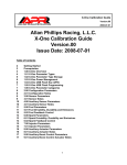
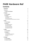
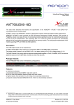
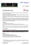
XTune User’s Manual
Version.00
2008-07-01
Allan Phillips Racing, L.L.C.
XTune User’s Manual
Version.00
Issue Date: 2008-07-01
Table of Contents
1
Getting Started
2
1.00 Installing XTune
2
1.01 Prerequisites
2
1.02 Running XTuneSetup.msi
3
2.00 XTune Files and Directory Structure
3
2.01 XTune Work Directory
4
2.02 XTune Work Directory Calibrations
4
2.03 XTune Work Directory Data Acquisition (Daq) Configurations
4
2.04 XTune Work Directory Data Store
5
2.05 XTune USB Flash Disk (UFD)
6
3.00 XTune USB Drivers
6
3.01 FTClean.exe Utility
6
3.02 Automatic USB Driver Install
7
3.03 Manual USB Driver Install
8
4.00 XTune Overview
9
4.01 XTune Parameter Types
10
4.02 XTune Parameter Type Storage
11
4.03 X-One Power Management
11
4.04 XTune Flash Programming
12
4.05 XTune Parameter Categories
12
4.06 XTune Spreadsheet Controls
13
4.07 XTune Chart Controls
14
5.00 Explorer Panel Overview
14
5.01 Explorer Panel Controls
14
5.02 Explorer Panel Tree Control
15
5.03 Explorer Panel Property Grid
15
5.04 Explorer Panel Definition and Notes
16
6.00 Instrument Panel Overview
16
7.00 Calibration Panels
16
7.01 Calibration Panel 1D Scalar Editing
17
7.02 Calibration Panel 2D Polynomial Sensor Editing
17
7.03 Calibration Panel 2D Interpolated Sensor Editing
18
7.04 Calibration Panel 3D Interpolation Editing
19
8.00 Data Panel Overview
20
8.01 Data Panel Spreadsheet Features
1
XTune User’s Manual
Version.00
2008-07-01
Getting Started
Thank you for choosing APR’s X-One product line.
The objective of this document is to detail the functions and operation of the XTune software
for calibrating (mapping / tuning) the X-One ECU. Before getting started with the installation,
please spend some time reading through this guide. Familiarity with its contents will greatly
aid the tuning workflow.
Warning:
Always have 2 people in the vehicle while performing calibration development work; 1 driver
and 1 tuner. This allows the tuner to focus on their work while keeping it safe.
1.00 Installing XTune
XTune is delivered as a single Microsoft Install file “XTuneSetup.msi”. This setup installs all
necessary components including working directories and files on the user's hard drive.
1.01 Prerequisites
XTune is compatible with any x86 based machine with a minimum of 500MB memory, 2GB
available disk space and an operating system capable of running Microsoft’s .Net Framework
3.5. The setup program will automatically detect and/or install .Net 3.5. XTune is compatible
with the following operating systems:
Windows Vista – all versions
Windows Server 2008, 2003
Windows XP
Windows 98
1.02 Running XTuneSetup.msi
XTune is installed by either double clicking on the “XTuneSetup.msi” file or by choosing
“Install” from the context menu after right-clicking on the file. Setup will guide you through
the installation and will only take a few minutes to complete.
2
XTune User’s Manual
Version.00
2008-07-01
2.00 XTune Files and Directory Structure
XTuneSetup will create the following directories in your “Program Files” folder:
“BackUp”
“Bin”
“Doc”
“Driver”
contains the original calibration and data acquisition files.
contains the XTune executable and necessary assemblies.
contains the user, parameter and calibration guides.
contains XTune’s USB driver and utilities.
2.01 XTune Work Directory
A working directory for calibration development and data acquisition is created under the
“Documents” folder in the user’s desktop:
3
XTune User’s Manual
Version.00
2008-07-01
2.02 XTune Work Directory Calibrations
“Apr”
“Apr\AprCal”
“Apr\AprCal\Tta40”
is the top folder.
is the parent folder for all calibration models.
contains all calibration files specific to the vehicle model.
Two calibration files with the “.AprCal” extension are included in this directory:
“Tta40.00.Na92.00.AprCal”
“Tta40.00.Na92.01.AprCal”
The ~.00.AprCal is a read-only base calibration generated by APR’s dynamometer and
vehicle calibration methodology. This file will be used for comparison with your calibration
making it easy to revert back to any part of the original base map. The ~.01.AprCal file is
your starting calibration file that is modifiable. All calibration for the Toyota Tacoma 4.0L will
be stored in this directory – including revisions. The user may change the “Na92.01” part of
the name that identifies their calibration. Here, “Na” stands for naturally aspirated and 92
indicates the octane level. The front part of the name “Tta40.00” indicates the software name
/version and is controlled by APR and is not modifiable (XTune will ignore renames to this
part).
2.03 XTune Work Directory Data Acquisition (Daq) Configurations
“Apr\AprDaq” contains a single data acquisition list/configuration file with the “.AprDaq”
extension:
“Main.AprDaq”
This file stores all data acquisition and instrument configurations maintained by XTune.
2.04 XTune Work Directory Data Store
“Apr\AprData”
“Apr\AprData\Tta40”
is the parent data store directory.
contains all dataset files specific to the vehicle model.
All dataset files with the “.AprData” extension are stored in this directory including an
example file:
“Main.Tta40.00.Na92.01.123.AprData.”
The “Main.Tta40.00” identifies the DaqList, software and version while the “Na92.01.123.”
part identifies the calibration/version and dataset number. In addition to storing all signals,
XTune will store the active calibration that produced the dataset so that there is never any
confusion about what calibration produced the dataset.
4
XTune User’s Manual
Version.00
2008-07-01
2.05 XTune USB Flash Disk (UFD)
The X-One ECU comes with a standard UFD for rapid calibration changes with the engine
running or not without the need for a PC. Any standard FAT32, FAT16 or FAT12 file systems
with the sector size set to 512 bytes and capacities up to 4GB are compatible. Simply store
your favorite calibration in the root directory on the supplied APR UFD and rename the file by
tagging it with “X1” in the leading characters:
“X1TTa40.00.Na92.01.AprCal”
The X-One will detect all UFD assertions/removals, search for any file starting with “X1” and
ending with the “.AprCal” extension, read and validate the file, then load it into RAM in less
than a second. After successfull loading, the X-One will flash the factory Malfunction
Indicator Lamp (MIL) a calibratable number of times based upon the user settable tuning
parameter “Config\CalID” in the map.
Any number of files can be loaded on the UFD, however, the X-One will only load the top
alpha-numerical file tagged with “X1”. This tagging system allows file selection while
preserving the calibration identity.
5
XTune User’s Manual
Version.00
2008-07-01
3.00 XTune USB Drivers
After the XTune software is installed, the USB device driver must be installed before
connecting to the X-One ECU. XTune’s USB device driver is fully Microsoft USB Certified.
However, with the surge in popularity of USB devices, it is possible that you may have an
older driver installed on your system that will conflict with XTune. Therefore, it is
recommended that you run a “Clean” utility first before installing the driver.
3.01 FTClean.exe Utility
The APR XTune Program Folder contains all the drivers and clean utility located in:
“Program Files\Apr\XTune\Drivers”
Locate the utility “FTClean.exe” and double click to launch the program. The user is
presented with the following dialogs:
Select the “Clean System” button and follow the instructions – the default FTDI setting is
correct. Note, the “Confirm” message box asks to cancel – hit “No” to continue. FTClean will
search your system and cleanup all conflicting USB drivers.
3.02 Automatic USB Driver Install
In the same driver folder is the latest USB device driver, double click on the “CDM
2.04.06.exe” program and the drivers will be install automatically.
6
XTune User’s Manual
Version.00
2008-07-01
3.03 Manual USB Driver Install
The automatic USB driver installation may not work on some operating systems depending
on its configuration. In the case you plug the X-One in for the first time and a Window’s
dialog ask “How do you want to search for driver software?” Select “Browse my computer for
driver software” and then select the following folder under the Apr directory:
“c:\Program Files\Apr\AprDrivers\CDM 2.04.06 WHQL Certified”
And Windows will install the driver properly.
7
XTune User’s Manual
Version.00
2008-07-01
4.00 XTune Overview
After installing the USB drivers, XTune is now ready to run. In the
Start Menu, either click on the top XTune shortcut or go to the
APR folder and select it there. It is also convenient to keep a
shortcut on a Quick Launch bar (as show to the right). Shortcuts
to all of XTune’s documentation can be located in the APR folder
as well. XTune can be started with or without the X-One attached
and may be connected/disconnected at any time. In addition, the
X-One computer can be powered by the USB port without having
to be connected in the vehicle for desktop programming.
The following diagram identifies the specific panels utilized in
XTune:
Explorer Panel
Calibration Tabs
Instrument Tabs
Instrument Panel
Calibration Panel
Chart Tabs
8
Instrument DockTab
Chart Panel
Calibration
DockTab
XTune User’s Manual
Version.00
2008-07-01
4.01 XTune Parameter Types
The following table lists all of XTune’s parameter types:
Type:
Identifier:
Equations:
Definition:
VS1
V1
V1 = Variable
Basic 1-dimensional variable located in RAM
RS1
R1
R1 = Scalar
Single number loaded from FLASH to RAM
RPs2
R2
R2 = Func(V)
Polynomial sensor class
RLs2
R2
R2 = Func(V)
Linear-interpolated sensor class
RLe2
R2
R2 = Func(X0)
Standard 2-point interpolation function.
RLe3
R3
R3 = Func(X0, X1)
Standard 4-point interpolation table.
.Y
.Y
Structure.Output
Type output value
.X0
.X0
Structure.Input0
Type first ordinate x input
.X1
.X1
Structure.Input1
Type second ordinate x input
.V
.V
Structure.InputVolts
Sensor voltage input ordinate
The number in the type/identifier indicates the parameters dimension (i.e. 1 = a single point
on a line, 2 = a line, 3 = a surface). The type identifier is displayed in the Property Grid
underneath the Explorer Tree while the simplified identifier (i.e. V1, R1, R2…) is utilized in
the tree to indicate dimension. The “VS1” type is a simple variable that represents signals
that change during runtime (i.e. RPM). All parameters starting with “R” are calibration types
that get loaded into RAM from FLASH during startup and only change if the user changes
them in XTune. The “RS1” type is a scalar calibration constant (i.e. a single number such as
the CalID – the calibration ID). The “RPs2” type is a polynomial sensor class containing the
A2D channel number, filter coefficient and polynomial :
Y = a0 + a1*V + a2*V^2 + a3*V^3 + a4*V^4
The coefficients for the polynomial must be supplied either by the sensor manufacturer or
may be fitted from the data using any math package (such as Matlab or Excel).
9
XTune User’s Manual
Version.00
2008-07-01
The “RLs2” type is a linear-interpolated sensor class containing the A2D channel number,
filter coefficient and an array of “Y-Values” that match the sensor’s transfer function.
The “RLe2” type is a standard 2-point interpolation:
Y = Function Of (X0)
Where the y-values can be adjusted to fit any single-valued line (one that doesn’t have more
than one y-point for each x-point) – sometimes referred to as a “fox function” for FofX.
The “RLe3” type is a standard 4-point interpolation:
Y = Function Of(X0,X1)
Where the y-values can be adjusted to fit any surface – sometimes referred to as either a
“table” or “map”.
The “.Y”, “.X0”, “.X1”, “.V” nomenclature is utilized in the AprDaq and AprData tree locations
to indicate the available fields for acquisition. For example, an auxiliary pressure sensor
measurement “P1” with the “RPs2” type will have available for measurement:
P1.Y – the sensor output
P1.V – the sensor input voltage
Likewise, a table calibration for the commanded air/fuel trajectory “AfrCmd” will have the
following fields available for measurement:
AfrCmd.Y – the 4-point interpolation output value
AfrCmd.X0 – the first input ordinate (Rpm in this case) utilized in the interpolation
AfrCmd.X1 – the second input ordinate (Load in this case) utilized in the interpolation
4.02 XTune Parameter Type Storage
The XTune parameter types are loaded into RAM from either the internal FLASH or UFD and
utilized during runtime allowing real-time tuning (RTT). In order to make calibration changes
permanent, the X-One’s Flash needs to be programmed (takes about 30 seconds with the
key-on and engine-off). Otherwise the next time the ignition power is cycled, the RAM will be
loaded again with the internal FLASH parameters. A “Sync” button is provided in XTune’s
Explorer panel that will refresh the RAM with the active calibration in case the ignition power
is ever cycled during a calibration session (engine can be running and only takes a second).
10
XTune User’s Manual
Version.00
2008-07-01
4.03 X-One Power Management
The X-One was designed to be USB or vehicle powered. The USB power feature allows the
X-One to be programmed at the desktop if desired (don’t have your auxiliary sensor plugged
in). In the vehicle, the X-One will either turn on when plugged into the USB port or with the
ignition key turned on. However, if the key is off and the USB plugged in, the X-One will
cycle to power off every 60 seconds – that will causes the USB port to cycle (as if you
removed the device, and then plugged it back in again). This is a reminder for you to always
keep the ignition key turned on during development or unplug the USB data cable between
development sessions.
4.04 XTune Flash Programming
The X-One was designed to allow the USB data cable to be connected and removed at will.
However, there are a few guide lines that will make development easier if followed:
1. Only attempt flash programming after the “Time” parameter on the first “Main” instrument
is counting. This affirms that the USB is synchronized with the X-One and ready to go.
2. Leave the X-One plugged in before starting XTune and try not to unplug it while it’s
operating . Unplugging while operating requires resetting the USB port and takes a few
seconds to establish synchronization. Leaving the USB data port plugged in before,
during and after assures seamless operation.
3. Never unplug the USB cable while performing a flash programming. This will leave the
X-One in an undetermined state. To recover, you will need to:
1. Shut down XTune with the USB data port unplugged
2. Turn off the ignition key and wait 2 minutes.
3. Plug in the USB data port , then re-start XTune.
4. Wait a minute and then issue a flash command to start a new download (the
“Time” parameter will not be counting until programmed successfully).
5. Don’t unplug the USB while programming
4. Turning the power off during programming should be avoided. However, the X-One
controls its own power-off so this will not corrupt the programming.
11
XTune User’s Manual
Version.00
2008-07-01
4.05 XTune Parameter Categories
The following table list the available calibration categories:
Category:
Definition:
Config
All configuration parameters such as the calibration ID and fuel type.
Sensors
All OEM sensors
AuxSensors
All auxiliary sensor channels
Fuel
All fuel calibration parameters
Spark
All spark calibration parameters
Injectors
All injector calibration parameters
Actuators
All auxiliary actuator parameters
BoostControl
All auxiliary boost control actuator parameters (dealer only)
In the Explorer panel, the categories are represented with folders. Double-clicking on them
will open all parameters for that category in a Calibration panel. There is never any need to
hunt for a parameter – just know the category, double-click the folder, and it will be displayed
in the calibration panel (more details to follow).
4.06 XTune Spreadsheet Controls
XTune uses an Excel spreadsheet control for all of its data manipulation:
12
XTune User’s Manual
Version.00
2008-07-01
The controls are similar to Microsoft Office allowing cell editing, drag-fill operations and cutpast operations:
Located in the lower left-hand corner are the sheet tabs that list the calibration files located in
the AprCal directory and are used for navigating between calibrations. Selections are made
either by dragging the mouse with the left mouse button held down or holding the “SHIFTKEY” and manipulating the arrow keys. Hit the “F5” key to exit edit mode and enable realtime table tracking (RTT) or hit the “ESC-KEY” to exit edit mode without enabling RTT. Every
spreadsheet can be zoomed in or out by holding the “CTR-KEY” and scrolling the mouse
wheel.
4.07 XTune Chart Controls
XTune uses the same chart control for data displays:
Chart Controls:
Zoom In: hold the “ALT-Key”, drag the mouse
with the left button held down to get a closeup of an area of interest.
Zoom In/Out: hold the “CTRL-KEY”, drag the
mouse with the left button held down either
up/down or right/left.
Pan: hold the “SHIFT-KEY”, drag the mouse
with the left button held down in the desired
direction.
13
XTune User’s Manual
Version.00
2008-07-01
5.00 Explorer Panel Overview
XTune’s Explorer panel contains all controls
for accessing and viewing the data.
Controls
Progress
5.01 Explorer Panel Controls
The “Live” combo-box selects the data
stream either from the live X-One USB
connection or a special Demo mode may be
selected for generating data as a learning
aid.
USB Port
ActiveCal
The “MSync MSave” combo-box is fixed
indicating that the user must manually save
their calibration and hit the “Sync” buttons if
power is ever cycled during calibration work.
Cals
Category
The “Sample” button triggers a data
acquisition.
Parameters
The “Sync” button downloads the active
calibration into RAM and may be hit at any
time.
Daq
The “Progress” bar indicates acquisition,
flash programming and sync operation
progress.
DaqList
Instruments
5.02 Explorer Panel Tree Control
The “XPort” node represents USB
connectivity and will load/unload the X-One
whenever it is attached or removed.
Data
Splitter
The “ActiveCal” node indicates what
calibration is currently flashed into the XOne. To change calibrations, simply drag
the desired calibration from the AprCal node
onto the active-cal node for programming. A
message-box will be displayed indicating
that the engine must be off and the ignition
key on for programming.
Properties
Definition
14
Notes
XTune User’s Manual
Version.00
2008-07-01
The “Check Boxes” indicate if a calibration needs to be saved after an edit has been
performed. A check means that it is saved, unchecked means it needs to be saved. This
also applies to the active-cal check-box, a check means that the active-cal is synchronized
with the calibration file located in the AprCal directory, uncheck indicates that a flash
operation needs to be performed. Simply click an unchecked box to save a calibration or
flash the X-One.
A “Context Menu” is available by right-clicking a node with available options dependent upon
the node selected. Operations available for the active-cal node are “Flash” and “Sync”. For
a calibration node in the AprCal directory, “New Revision” is available for creating a new copy
of the calibration with an incremented calibration revision number. For “Post Charting” under
the Daq-node, an option to create a new post chart (charts created automatically for
acquisition datasets). The same option is available for creating new charts in a collected
dataset.
After the listed calibration are the available categories. Double-click on any category to view
the calibration panel that displays all of its parameters. Under a category will be listed the
parameters that may be drag/dropped onto the “DaqList” to add to the acquisition. The
parameters listed under the DaqList may be drag/dropped onto a gauge listed under the
“Instruments” node to change the display. Select any parameter or chart and hit the
“DELETE-KEY” to remove. The AprDaq file is automatically saved after every edit.
The last node is the AprData that organizes the collected datasets. Double-click and
.AprData node to display the data for analysis and view the dataset. New charts are created
with the context menu and drag/dropping parameters onto the new chart node.
5.03 Explorer Panel Property Grid
The property grid displays all parameter information for the selected node. Some properties
are read-only but others allow editing like the number of samples to collect on a “Instrument”
node.
5.04 Explorer Panel Definition and Notes
Below the property grid are the “Definition” and “Notes” windows that display the parameter
definition and notes for the selected node. Notes may be added to every parameter,
calibration or node to aid in the tuning work.
15
XTune User’s Manual
Version.00
2008-07-01
6.00 Instrument Panel Overview
The “Instrument” panel displays the selected parameter’s real-time value. The displayed
parameter may be changed by drag/dropping from the “DaqList” node onto the desired
gauge. The vertical “Instrument Tab” on the far left allows selection of different instruments.
The parameters “Alarm Low”, “Alarm High”,
“Multiplier”, and “Multiplier Value” may be changed
in the property grid of the selected gauge.
7.00 Calibration Panel Overview
Double-clicking a category will display its
calibration panel listing all of its parameters. The
vertical calibration tab on the far-left selects
between scalar (1D) parameters listed in a spread
sheet and has a separate tab for 2D and 3D
parameters individually. Click on the desired tab to
see its parameter panel.
The horizontal tab allows navigation between all
opened panels.
7.01 Calibration Panel Scalar Editing
The “Config” category scalars are displayed to the
right listing its parameters that may be edited. The
top parameter shown is “CalID” that identifies the
loaded calibration by flashing the MIL. At the
bottom of this panel are the sheet tabs for different
calibrations listed in the “AprCal” directory.
16
XTune User’s Manual
Version.00
2008-07-01
7.02 Calibration Panel 2D Polynomial Sensor Editing
The 2D polynomial sensor panel lists the real-time numeric values for the output and analogto-digital converter (ADC) voltage. Next is the spreadsheet control for selecting the channel,
filter and polynomial coefficients. Values for the filter coeficient are from 0 to 1, the lower the
value more filtering is applied (standard low-pass/rolling average filter). A value of 1 results
in no filter at all. Below the spreadsheet is a chart displaying the equation x vs. y.
7.03 Calibration Panel 2D Interpolated Sensor Editing
Similar to the polynomial sensor is the linear-interpolated sensor. Here the y-values are set
directly with the desired transfer function. The 2D linear-interpolation is identical.
17
XTune User’s Manual
Version.00
2008-07-01
7.04 Calibration Panel 3D Interpolation Editing
The 4-point interpolation panel also displays the real-time output, and input ordinates. The
chart panel allows selecting between 3D and series viewing. The splitter can be collapsed
allowing full spreadsheet view or right-clicked to cycle between vertical and horizontal
splitting. Use the “CTRL-KEY” and mouse wheel to size the spreadsheet to the desired size.
18
XTune User’s Manual
Version.00
2008-07-01
8.00 Data Panel Overview
Double-click on any file located under the “AprData” node to open the dataset for charting.
On the far left is the vertical “Chart Tab” for selecting the desired view. As stated earlier
parameters may be added/deleted from a chart using the tree control as well as creating new
charts using the context menu. Click on any signal to highlight (shown in thick yellow) a
signal and display a value-label. Double-click any point to pin the value-label at any location.
Below the chart is the dataset that will track to the selected time point chosen. The context
menu allows 3D ribbon views, signal stacking, resetting the chart or value-labels, left and
right y-axis units selection, x and y scrollbars for navigating while zoomed in and printing.
19
XTune User’s Manual
Version.00
2008-07-01
8.01 Data Panel Spreadsheet Features
Data from the spreadsheet can be cut-and-pasted into any Excel compatible spreadsheet for
further analysis.
20