1
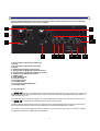
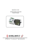
USER’S MANUAL SUB 10 ACTIVE STUDIO SUBWOOFER CONTENTS page INTRODUCTION GENERAL INFORMATION 3 REAR PANEL REAR PANEL INPUTS/OUTPUTS SWITCHES INDICATORS 4 4 5 6 TECHNICAL SPECIFICATIONS TECHNICAL SPECIFICATIONS 7 SAFETY INSTRUCTIONS SAFETY INSTRUCTIONS 8 MISCELLANEOUS CARE 9 INTRODUCTION Congratulations on your purchase of the APS SUB 10 active studio subwoofer. SUB 10 is designed to provide many years of excellent and trouble free audio reproduction. It is most important, however, that you take a few minutes to read this manual. It contains essential information to make you get the best from your new SUB 10. SUB 10 is a professional active studio subwoofer, designed for accurate sound realization. This subwoofer is suitable for small/mid-sized: – recording studios, – broadcasting studios, – TV studios, – multimedia studios, – post production facilities, – mastering, – digital workstations, – home recording studios, audio monitoring systems of the highest quality. SUB 10 10 is a professional active studio subwoofer equipped with sub-bass loudspeaker driver of 29 cm in diameter, class D power amplifier 400W at 4Ohm mounted on the rear panel, there are also calibrated controls, protections, indicators, and the input/output terminals. SUB 10 is designed for operation in stereophonic or multi-channel systems (5+1 or 7+1 and larger) such as DOLBY, DTS, THX, etc. APS Sp. z o.o. Obłaczkowo 16 62-300 Września www.aps-company.com e-mail: [email protected] 3 REAR PANEL Correct setup and placement in the room is essential to achieve optimal performance from your subwoofer. Please follow the instructions on the following pages. 1 4 2 5 13 3 6 7 8 9 10 11 12 1. XLR symmetrical (balanced) output (right channel) 2. XLR symmetrical (balanced) input (right channel) 3. Unbalanced input RCA (right channel) 4. XLR symmetrical (balanced) input (left channel) 5. XLR symmetrical (balanced) output (left channel) 6. Unbalanced input RCA (left channel) 7. PHASE switch 8. UNFILTERED switch 9. CUT OFF switch 10. Indicatros (diode) 11. VOLUME switch 12. Three-position VOLUME switch 13. Stand-by switch 1-6. Inputs/outputs The SUB 10 subwoofer is equipped with two pairs of balanced XLR inputs and outputs, one pair per channel. The inputs support combo connectors, which can be used to connect the subwoofer using cables with XLR or balanced TRS connectors (6.3 mm). The subwoofer does not modify the signals sent to XLR outputs which are active even after the power is turned off. The SUB 10 rear panel also has unbalanced RCA inputs, one per channel. The two inputs are used for stereo signal. The subwoofer in this case aggregates the low frequency components of left and right channel signals, and the result is delivered to the subwoofer speaker after correction. In the case of a source with a separate subwoofer channel, use one input from the set of R or L inputs, for example, the right XLR or RCA input, additionally marked LINE IN. 4 When sending signals to both R and L inputs, the subwoofer plays the sound at a level higher by 6dB, which results from the operation of aggregation. Switches The subwoofer's rear panel features switches used to find the optimal settings of the device in order to work in a variety of acoustic and electric conditions. Each of the switches is described below. 7. PHASE switch The phase switch is used to match the subwoofer phase to the phase of monitor speakers. If the distance of the listener to the subwoofer is the same or slightly less than the distance to the monitor speakers, set the PHASE switch in the down position, i.e. at 0 degrees. This situation occurs, for example, when the monitor is placed directly on the subwoofer in a system with two subwoofers. And when this distance is greater by about 1 - 2 metres, then set the switch in the up position, i.e. at 180 degrees. A situation may occur when, for example, a single subwoofer is positioned on the floor about 0.5 - 1.5 metres behind the monitors. It is a good idea to test the position of the subwoofer in the listening room and of the PHASE converter, because the final sound is heavily dependent on the vibration modes of the room at low frequencies. In addition, monitor speakers or other devices in the electroacoustic path can reverse the phase. 8. UNFILTERED switch The switch turns off correction, i.e. the subwoofer filters responsible for its sound. When the UNFILTERED (LFE) switch is set in the down position, the appropriate correction is enabled and the CUT OFF controller is active. In the up position, the correction is disabled and the CUT OFF controller is inactive. In most cases the UNFILTERED (LFE) switch is in the down position, with the filters enabled. If the tone of the sub-bass channel is imposed by an external device, e.g. when an LFE channel (Low-Frequency Effects) is the source, you can turn off the subwoofer correction. However, it is a good idea to test both settings. 9. CUT OFF switch The CUT OFF switch is an eight-position controller for the upper cut-off frequency of the SUB 10 subwoofer. It allows you to adjust the crossover frequency between the subwoofer and the monitors, depending on the monitors' ability to play low frequencies. It is the best to start the adjustment with the smallest values, reasonably increasing the CUT OFF value while controlling the subwoofer volume using the VOLUME switch. Make sure that the PHASE switch is set in the desired position. 11. VOLUME switch Fine-tuning the sensitivity of the SUB 10 subwoofer, or simply its volume, is possible using the eight-position VOLUME switch. The subwoofer is equipped with a switch instead of a potentiometer. This allows for, among other things, repeatable and reliable adjustment of the subwoofer sensitivity to the sensitivity of monitor speakers, or for repeating the same settings in subsequent subwoofers in the system, or restoring the settings used in the past. The switching interval is 1.5dB. This switch cooperates with the three-position VOLUME switch. The resulting value of attenuation or gain in decibels is the sum of values indicated by the positions of both switches. 12. Three-position VOLUME switch The three-position VOLUME switch allows for adjusting the sensitivity/volume of the subwoofer in a wide range. The switching interval is 10dB. This switch works with the eight-position VOLUME switch. The total adjustment range of the two switches is 30.5dB. 13. STAND-BY switch The STAND-BY switch allows for saving energy when the subwoofer is not used in a continuous manner. With the switch in the down position, the STAND-BY system is active, and the subwoofer turns off after a certain time in the absence of a sound signal, and turns on when the signal appears at the input. SUB 10 can be used with a variety of signal sources. The switches make it possible to precisely and evenly adjust the levels in each of the subwoofers in both a stereophonic and multichannel system. 5 Example: SUB 10 and COAX. Configuration and switch settings in a system with the SUB 10 subwoofer and the COAX monitor. The subwoofer is on the floor, pushed back about 0.5 to 1.5 metres behind the monitor The PHASE switch is in the 180-degree position, The CUT OFF frequency is around 40 - 57Hz, depending on the size of the room and arrangement of speakers, The three-position VOLUME switch is at 0dB and the eight-position VOLUME switch is from -3 to 3 dB, depending on the size of the room and arrangement of speakers. The subwoofer is directly below the monitor The PHASE switch is in the 0-degree position, The CUT OFF frequency is around 40 - 57Hz, depending on the size of the room and arrangement of speakers, The three-position VOLUME switch is at -10dB and the eight-position VOLUME switch is from 0 to 6 dB, depending on the size of the room and arrangement of speakers. VOLUME settings shown above are estimated, because they depend to a large extent on the acoustic properties of the listening room, as well as the preferences of the listener. Keep in mind that a replacement of two subwoofers working in close proximity to a single one means a decrease in the volume level by 6dB. In case of a setup with a single subwoofer, it is best to place it in front of the listener. 10. Indicators Stand-By If the STAND-BY switch is in the ON (down) position, the subwoofer goes into standby mode after some time if no signal is input. The STAND-BY indicator light turns on. Clip When a signal which is too strong is sent to the subwoofer input, and VOLUME switches are in the maximum positions, clipping will occur in the subwoofer's internal amplifier. The CLIP light will then flash along with the input sound signal, or light up continuously in the case of significant clipping. On Green/Error Red After turning the power on, the indicator light is red, and when the subwoofer is ready, it turns green. Continuous red light indicates an error or malfunction. In this case, contact a qualified service representative. 6 TECHNICAL SPECIFICATIONS Active Studio Subwoofer SUB 10 Type Active – Class D power amplifier Hypex: 400 W @ 4 2.5 dB: 19 Hz 90 Hz Free Field Frequency Response SPL in Free Field @ 1m Dimensions: Height Width Depta RMS: 108 dB (single subwoofer) Peak: 116 dB (pair of subwoofers) 39 cm 39 cm 40 cm (15.35’’ x 15.35’’ x 15.75’’) Weight 24 kg (53 lbs) Loudspeaker Subbass Loudspeaker 29 cm Diaphragm: cellulose, surround: rubber Amplifier Subbass Loudspeaker Power Amplifier 400 W RMS @ 4 (270 W RMS @ 6 ) THD distortions Typ 0.01%, Max 0.05% 20Hz<f<20kHz, Pout < PR/2 Max 0.04% 20Hz<f<20kHz, Pout = 1W Calibrated Controls Input Sensitivity Switch / VOLUME (8 positions) -4.5dB, -3dB, -1.5dB, 0dB, 1.5dB, 3dB, 4.5dB, 6dB Input Sensitivity Switch / VOLUME (3 positions) -20dB, -10dB, 0dB Low-pass filter Switch CUT OFF 40Hz, 45Hz, 50Hz, 57Hz, 63Hz, 71Hz, 80Hz, 90Hz Filters By-Pass Switch UNFILTERED (LFE) Position down: filters ON Position up: filters OFF PHASE Switch 0 degrees, 180 degrees Position down: active STAND-BY Position up: continuous mode (Stand-by OFF) STAND-BY Switch Inputs, Outputs INPUT right ( R )and left ( L ) Two types (common socket Combo): XLR symmetrical (balanced) TRS symmetrical (balanced) “6.3 mm” and RCA nonsymmetrical Input impedance 10 k XLR symmetrical Output impedance 100 OUTPUT, Loop Through Protections Subbass Loudspeaker Protection Pop-free start and stop control Power Amplifiers Protections Overcurrent protection Power Amplifiers Protections Overvoltage protection Signaling Devices STAND-BY ON Orange LED 7 CLIPPING detected Red LED POWER ON / DC-error detected Green LED / Red LED SAFETY INSTRUCTIONS The lightning flash with an arrowhead symbol within an equilateral triangle, is intended to alert the user to the presence of uninsulated “dangerous voltage” within the product’s enclosure that may be of sufficient magnitude to constitute a risk of electric shock to persons. The exclamation point within an equilateral triangle is intended to alert the user to the presence of important operating and maintenance (servicing) instructions in the literature accompanying the product. 1. Read these instructions. 2. Keep these instructions. 3. Heed all warnings. 4. Follow all instructions. 5. Do not use this apparatus near water. 6. Clean only with dry cloth. 7. Install in accordance with the manufacturer’s instructions. 8. Do not install near any heat sources such as radiators, heat registers, stoves, or other apparatus (including amplifiers) that produce heat. 9. Do not defeat the safety purpose of the polarized or grounding-type plug. A polarized plug has two blades with one wider than the other. A grounding type plug has two blades and a third grounding prong. The wide blade or the third prong are provided for your safety. If the provided plug does not fit into your outlet, consult an electrician for replacement of the obsolete outlet. 10. Protect the power cord from being walked on or pinched particularly at plugs, convenience receptacles, and the point where they exit from the apparatus. 11. Only use attachments/accessories specified by the manufacturer. 12. Use only with the cart, stand, tripod, bracket, or table specified by the manufacturer, or sold with the apparatus. When a cart is used, use caution when moving the cart/apparatus combination to avoid injury from tip-over. 13. Unplug this apparatus during lightning storms or when unused for long periods of time. 14. Refer all servicing to qualified service personnel. Servicing is required when the apparatus has been damaged in any way, such as power-supply cord or plug is damaged, liquid has been spilled or objects have fallen into the apparatus, the apparatus has been exposed to rain or moisture, does not operate normally, or has been dropped. Warinng! To reduce the risk of fire or electrical shock, do not expose this equipment to dripping or splashing and ensure that no objects filled with liquids, such as vases, are placed on the equipment. This apparatus must be earthed. Use a three wire grounding type line cord like the one supplied with the product. Be advised that different operating voltages require the use of different types of line cord and attachment plugs. Always observe the local safety regulations. Ensure that the factory-set power requirements for the device (refer to the label on the back of the monitor) corresponds to the mains supply in your region. This equipment should be installed near the socket outlet and disconnection of the device should be easily accessible. To completely disconnect from AC mains, disconnect the power supply cord from the AC receptacle. The mains plug of the power supply shall remain readily operable. Do not install in a confined space. Do not open the unit - risk of electric shock inside. 8 MISCELLANEOUS Care Components of the highest quality are used in your SUB 10 subwoofer. This assures years of trouble free operation. Following precautions should still be made though. Avoid running the system into severe clipping. Even there is an advanced protection system, you may be able to destroy your subwoofer by severe overpowering. The limiter works over a certain range, but exceeding this level may send a severely clipped signal to your sub-bass loudspeaker driver. When a noticeable distortion occurs, please turn down the level to your subwoofer. Avoid hot plugging the equipment connected to the subwoofer. Always turn off the subwoofer and other equipment when plugging or unplugging signals, or switching equipment on or off. Do not touch the sub-bass loudspeaker driver by hand. 9