1
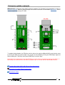
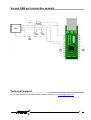
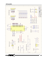
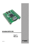
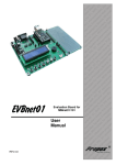
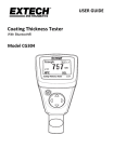
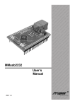
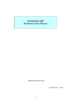
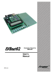
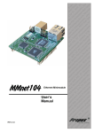
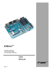
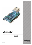
MMusbVNC2
User’s
Manual
REV 1.0
u rd ST, ta- rve
l
a oa ,
S e
Ev B VR ers b S d
l
n
io 1, A trol We mo
t
i
a ‘5
in ron ed
r
c
fo cro dd s M the
e
s
d e
i
m mb oar rs, peC E B e S
PI its ng roll gh r
K pi nt Hi fo
r
y
o
rte tot roc FID ers s
o c
r
Pr mi s, R mm lle
rs or ler gra tro
f ol
n
o
s
pr oco CB
e nt r
l
u o
m icr s, P for
c
e
t
t
m m ds
s
e
ne Sy T
st oar lS
n
y
I
,
s B
ro
ed PIC or ion ont b
s
,
c e
R ce luat cro W
V
o
A pr va mi ed iro E
dd
ic ng PIC be ds m
M ni T, m
r
,
ig , S s E oa rs
s
e
B
t
l
de VR Ki ng rol
h
t
i
r
, A rte typ on Hig
1
c
‘5 Sta oto ro ID r
e
ic F
rs P
le rs or m s, R mm ve s f ller gra ntrl
r
Se ule tro pro oco
od con ms icr s,
m
ni net ste T m stem
y S y
r
ohe In S C, r s B
t
e d
PI eso tion ice
,
e R oc ua m
Sp AV opr val IC e
r r
fo ic g E T, P mb
E
rs s M nin , S
s ing
r ig
t
R
i
e
l
ol des , AV er K typ
B `51 tart roto roS s P mic ,
PC for
s
s ller er for lers
d
l
ar tro erw les tro on b S du con ram
c
ro We imo et rog o
n
n
p
ed Mi her m roc
d
d ds et ste ic
ar rs, Sy T m r
o
B olle In , S so
tr ed IC oce ign
P
s
co Spe R, opr De
V cr B Rion
h
t
ig r A Mi
PC lua
H f o rs
,
s oneasolution
e Many ideas
s
er roll em Ev ds
m nt
st ng oar
y
o
c
S
ni B
Introduction
Thank You for buying our minimodule MMusbVNC2.
MMusbVNC2 is low-cost integrated Host USB module. It is based on FTDI's VNC248L1B device. Module allow communicate to MCU, PLD or FPGA via one of the three
interfaces: UART, SPI and parallel FIFO. Interface selecting is possible by two shorts:
SEL1 and SEL2. VNC2-48L1B chip, chich is a hart of our module, transparently
handles the FAT File structure and is fully compliant with USB 2.0 specification. Our
module is delivered with VDAP firmware installed, which allow to communication with so
popularly USB Flash drives.
MMusbVNC2 is made in two-layer printed circuit bard technology. It Has 256k byte
program Flash ROM memory and 16k byte SRAM data memory. All signals are driver via
24 pin, 1.1inch wide footprint. Integral power control allow to power external devices.
Choosing our minimodule is the first step for projects, which should be done in the short
time. MMusbVNC2 could be used as part of prototype eliminating necessity of designing
circuit board and final circuit in which module is fitted like "sandwich shape".
We wish you were successful at designing and using new devices
Features MMusbVNC2
•
Low dimension, USB type A socjet and second USB port available by module pins.
•
Fully compliant with USB 2.0 specifi cation – USB full speed (12 Mbps) and low speed
(1.5 Mbps) USB host and slave device compatible.
•
Single 5V Power Supply
•
Integral power control allow to power external devices by 3.3V power supply form
LP2951ACM-3.3
•
Power indicator (PWR) and USB traffic indicatros LED’s (LED1, LED2).
Power On
LED1 and LED2 flash alternately for 2 seconds.
Repeated until monitor connects.
USB Disk Initialisation
LED1 on, LED2 off
USB Disk Ready
LED1 off, LED2 on
USB Disk Removed
LED1 off, LED2 off
Commands from monitor to USB Disk
LED1 off, LED2 flashes
Commands from monitor Port with USB Disk
removed
LED1 off, LED2 off
2
•
Firmware programming control pins PG# and RS# brought out onto jumper pin connectors.
•
Program or update firmware via USB Flash dis kor via SPI / UART / Paralel FIFO
Interface
SEL1
SEL2
UART
Pull-up
Pull-up
SPI
Pull-down
Pull-up
Parallel FIFO
Pull-up
Pull-down
UART
Pull-down
Pull-down
Applications Areas
•
•
•
•
•
•
•
•
Interface USB Flash drive to MCU / PLD / FPGA
USB Flash drive to USB Flash drive file transfer interface
Digital camera to USB Flash drive or other USB slave device interface
MP3 Player to USB Flash drive or other USB slave device interface
USB MP3 Player to USB MP3 Player
Mobile phone to USB Flash drive or other USB slave device interface
GPS to mobile phone interface
Interface USB Flash drive to Printer
General Description
MMusbVNC2 is a host / slave USB interface, which include new functionality. All signals are driver
via 24 pin, 1.1inch wide footprint. Single USB port type A is available on module and second USB
port type A is available by pins.
MMusbVNC2 allow to work with three interfaces, selectable by two gold-pin junction placed directly
on minimodule:
•
•
•
UART
SPI
Parallel FIFO
FTDI company is delivering with VNC2-48L1B chip, 6 different types of firmware, which are
available on www.vinculum.com website. Upgrade or installation a new firmware is easy. It can by
done by using software which is also available on product website and our else module,
MMusb232. Connection schematic is available in second part of this manual.
3
Module Pin-Out
Figure 2. MusbVNC2 Top view (component side)
Pin Definitions determined by type of interface
Pin
Name
PCB
Type
UART
6
8
9
10
11
12
13
14
15
16
17
19
20
ADBUS0
ADBUS1
ADBUS2
ADBUS3
ADBUS4
ADBUS5
ADBUS6
ADBUS7
ACBUS0
ACBUS1
ACBUS2
ACBUS3
ACBUS4
AD0
AD1
AD2
AD3
AD4
AD5
AD6
AD7
AC0
AC1
AC2
AC3
AC4
I/O
I/O
I/O
I/O
I/O
I/O
I/O
I/O
I/O
I/O
I/O
I/O
I/O
TxD
RxD
RTS#
CTS#
DTR#
DSR#
DCD#
RI#
TXDEN#
Parallel
FIFO
D0
D1
D2
D3
D4
D5
D6
D7
RXF#
TXE#
RD#
WR
SPI
SCLK
SDI
SDO
CS
4
Pin Definitions
Pin
No.
Name
Type
1
5V0
Input
2
LD1
Output
3
LD2
Output
4
5
6
7
8
9
10
11
12
13
14
15
16
17
18
19
20
21
22
U1P
U1M
AD0
GND
AD1
AD2
AD3
AD4
AD5
AD6
AD7
AC0
AC1
AC2
GND
AC3
AC4
AC5
RS#
I/O
I/O
I/O
GND
I/O
I/O
I/O
I/O
I/O
I/O
I/O
I/O
I/O
I/O
GND
I/O
I/O
I/O
Input
23
PG#
Input
24
3V3
Output
Description
5V module supply pin. Provides the 5V output on the
USB type A socket, and the 3.3V supply, via an onboard LP2951PCM-3.3.
USB Port 1 activity indicator LED. This pin is hard wired
to a green LED1.
USB Port 2 activity indicator LED. This pin is hard wired
to a green LED2.
USB Data Signal Plus - USB host/slave port 1.
USB Data Signal Minus - USB host/slave port 1.
AD bit 0.
Ground supply pin.
AD bit 1.
AD bit 2.
AD bit 3.
AD bit 4.
AD bit 5.
AD bit 6.
AD bit 7.
AC bit 0.
AC bit 1.
AC bit 2.
Ground supply pin.
AC bit 3.
AC bit 4.
AC bit 5.
Can be used by an external device to reset the module.
It can be used with PROG# signal to program firmware.
This pin is used with RESET# signal to program
firmware.
3.3V output from module's on board LP2951PCM-3.3.
Technical Data
Dimensions
Weight
Power supply
: 60 x 18,8 x 18,8 mm
: około 8 g
: 5V
5
Mechanical Dimensions
Dimensions are in millimeters.
1mils – 1/1000 inch
100miles = 2,54mm
6
Firmware update example
MMusbVNC2 is delivered with VDAP firmware installed. Full firmware's documentation is able on
product webside. Below is placed sample connection schematic to minimodule MMusb232, which
allow to install firmware by PC USB:
To enable the bootloader, the PG# pin must be driven low and the MMusbVNC2 must then be reset
by driving the RS# pin low then high. Run mode can be enabled by driving the PROG# pin high and
then resetting the VNC2 by driving the RESET# pin low then high.
Note that for the bootloader to be active PG# pin must be driven low before powering the VNC2. If
the PG# pin is not driven low, the VNC2 will power up in run mode with the bootloader inactive.
Firmware dla układu VNC2-48L1B oraz Oprogramowanie
Vinculum II Firmware Flash Programming
Vinculum II Tools
7
Second USB port connection example
Technical Support
If You have a problem with MMusbVNC2, please contact us at [email protected].
8
Schematic
9