1
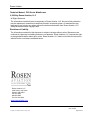
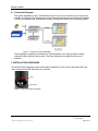
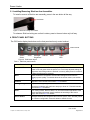
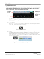
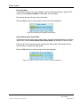
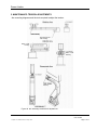
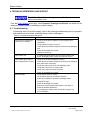
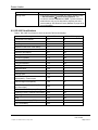
ELECTRONIC REVISION CONTROLLED Document Number 100923 Rev C Rosen Aviation Technical Manual, 7002 Series WideScreen © 2008 by Rosen Aviation, LLC All Rights Reserved The information contained herein is proprietary to Rosen Aviation, LLC. No part of this publication may be reproduced, transmitted, transcribed, stored in a retrieval system, or translated into any language in any form by any means without the written authorization from Rosen Aviation, LLC, except as allowed under copyright laws. Disclaimer of Liability The information contained in this document is subject to change without notice. Because we are continuously improving and adding features to our products, Rosen Aviation, LLC reserves the right to change specifications without prior notice. Rosen Aviation, LLC shall not be liable for technical or editorial errors or omissions contained herein. Rosen Aviation, LLC 1020 Owen Loop South Eugene, OR 97402 541.342.3802 888.668.4955 Fax: 541.342.4912 www.rosenaviation.com Document Number: 100923 Template: 4.2.3-6-FM; Revision A; 16 May, 2005 Revision: Date: 9/18/08 C Page 2 of 21 Rosen Aviation Contents 1. INTRODUCTION .................................................................................................................4 1.1. Unpacking .....................................................................................................................4 2. DISPLAY CONNECTIONS .................................................................................................4 2.1. Connection Diagram .....................................................................................................5 3. INSTALLATION GUIDELINES ...........................................................................................5 3.1. Installing/Removing SlimLine Arm Assemblies .............................................................6 4. FRONT PANEL BUTTONS.................................................................................................6 4.1. Navigational Soft Keys ..................................................................................................7 4.1.1. Source Select ................................................................................................................... 7 4.1.2. Scale ................................................................................................................................ 7 4.1.3. Backlight Brightness ....................................................................................................... 10 4.1.4. Contrast .......................................................................................................................... 10 4.2. On-Screen Menus .......................................................................................................11 4.2.1. Image Adjustments Menu ............................................................................................... 11 4.2.2. Advanced Menu .............................................................................................................. 13 5. MAINTENANCE: TENSION ADJUSTMENTS ..................................................................17 6. TECHNICAL REFERENCES AND SUPPORT .................................................................18 6.1. Troubleshooting ..........................................................................................................18 6.2. DO-160E Qualifications ..............................................................................................19 6.3. Technical Support .......................................................................................................20 6.4. Specifications..............................................................................................................20 7. DEFINITIONS....................................................................................................................20 8. REVISION HISTORY ........................................................................................................21 Document Number: 100923 Template: 4.2.3-6-FM; Revision A; 16 May, 2005 Revision: Date: 9/18/08 C Page 3 of 21 Rosen Aviation 1. INTRODUCTION This manual describes how to install the Rosen 7” WideScreen 7002 series display onto your aircraft. It contains everything you need to know to wire the display and confirm that it is functioning correctly. Note: Only trained and qualified personnel should perform installation and service. 1.1. Unpacking The parts shipped with the 7” WideScreen 7002 series display Outline and Installation Drawing 7002 – specific to each display/arm combination 7002 display with arm Display Manuals CD, (P/N 9003678) 7” WideScreen 7002 User’s Guide – (P/N 101327) – leave in the plane The Outline & Installation drawings—specific to each display/arm combination —are also available at www.rosenaviation.com. From the Rosen Aviation home page, select Support Drawings and Pinouts, and search for the drawing by model number or browsing by product category. 2. DISPLAY CONNECTIONS There are several ways to connect the 7002 series display to an aircraft’s data systems. Use the following pinout descriptions on page 2 of the Outline and Installation drawing to assist in the wiring process. Pay close attention to the pinout information while completing wiring connections. Note: This display is for entertainment purposes only; connect to the non-critical power bus. Document Number: 100923 Template: 4.2.3-6-FM; Revision A; 16 May, 2005 Revision: Date: 9/18/08 C Page 4 of 21 Rosen Aviation 2.1. Connection Diagram The typical installation of the 7” WideScreen monitor is one or more monitors on an arm mount, sidewall, or bulkhead. The following connection diagram illustrates how to configure the displays to create a complete cabin entertainment system or integrate a display into an existing system. Figure 1 Typical arm mount installation These displays are typically connected to a video distribution unit, which provides a single composite video signal to each monitor. The video distribution box performs the source selection. 3. INSTALLATION GUIDELINES Ensure that when plugging the arm into the base receptacle, the set screw in the base follows the arm’s keyed slot and the connection is not forced. Slot Set screw Figure 2 Arm mount base receptacle Document Number: 100923 Template: 4.2.3-6-FM; Revision A; 16 May, 2005 Revision: Date: 9/18/08 C Page 5 of 21 Rosen Aviation 3.1. Installing/Removing SlimLine Arm Assemblies To install or remove a SlimLine arm assembly, press in the arm button all the way. Arm button Figure 3 SlimLine locking arm feature To release a SlimLine locking arm so that it rotates, press in the arm button only half way. 4. FRONT PANEL BUTTONS The 7002 series display has buttons on the front panel as its only control method. Power On/Off Scale Source Backlight Contrast Select Brightness Figure 4 7002 button layout Menu Power LED Table 1 7002 front panel buttons Button How it Works Power On/Off Turns the power on and off to the display. The LED indicator is red when the power is off, and green when the power is on. Previously adjusted settings of brightness and scaling mode are retained in memory when power is turned off, or when aircraft power is removed. Menu Opens a submenu of options to access other settings and fine-tune the display’s picture quality. For details about the on-screen menus, see section 4.2. Contrast Adjusts the LCD contrast. See section 4.1.4 for details. Backlight Brightness Adjusts the backlight brightness. If the button is held down for more than one second the brightness will continue to step up or down in ¼-second intervals. See section 4.1.3 for details. Scale Four scaling modes: Normal, Wide, Full, and Cinema allow adjustment of the picture expansion that most closely matches the encoding of the source image. See section 4.1.2 for details. Source Select Changes between two composite video sources (NTSC, PAL, SECAM), which are customer configurable. Press this button to switch sources. Document Number: 100923 Template: 4.2.3-6-FM; Revision A; 16 May, 2005 Revision: Date: 9/18/08 C Page 6 of 21 Rosen Aviation 4.1. Navigational Soft Keys The icons on the display buttons indicate basic functions. In addition to the basic functions, the buttons act as soft keys that perform secondary navigational functions to adjust picture quality in dialog boxes and the on-screen menus. When you press a button and see a bar of blue soft keys, as shown below, press the corresponding display button. The label of the menu soft key changes depending on the function it is performing Secondary soft keys Basic function buttons Figure 5 Soft key buttons Note: Before changing the display settings, try both default color modes first to determine which set of default colors you like best. See Restore Factory Defaults on page 14 for more information. 4.1.1. Source Select Switch input sources by pressing the Source Select button (shown below). You will hear a relay click, which indicates the source changed. Figure 6 Source select button 4.1.2. Scale Change the scaling mode by pressing the Scale button (shown below). Press the ◄ or the ►soft key to switch the display between the different scaling modes (described below). Highlight the optimal mode for the image source and press Set to set the scaling mode and exit the dialog box. Figure 7 Scale button, settings, and soft keys Document Number: 100923 Template: 4.2.3-6-FM; Revision A; 16 May, 2005 Revision: Date: 9/18/08 C Page 7 of 21 Rosen Aviation Normal Mode Normal mode displays a standard 4:3 aspect video without alteration. A standard 4:3 source image will appear with vertical black bars on the left and right side of the screen, as shown in Figure 8. If the image source is letterboxed, then there will be horizontal bars at the top and bottom of the image as well. Figure 8 Standard 4:3 aspect test pattern in Normal Mode Widescreen 16:9 images will appear horizontally compressed with vertical black bars on the left and right side of the screen, as shown in Figure 9. Figure 9 Widescreen 16:9 aspect test pattern in Normal Mode Document Number: 100923 Template: 4.2.3-6-FM; Revision A; 16 May, 2005 Revision: Date: 9/18/08 C Page 8 of 21 Rosen Aviation Wide Mode Wide mode displays a standard 4:3 source video in 16:9 aspect ratio by expanding the image horizontally. The expansion maintains normal aspect in the center region while stretching the rest of the image to fill the screen, as shown in Figure 10. Widescreen 16:9 will be displayed full screen with minor central compression, as shown in Figure 11. If the source image is letterboxed, there will be black bars at the top and bottom of the image. Figure 10 Standard 4:3 aspect test pattern in Wide Mode Figure 11 Widescreen 16:9 aspect test pattern in Wide Mode Full Mode Displays standard 4:3 source video in 16:9 aspect ratio by expanding the entire image horizontally, as shown in Figure 12. If the source image is letterboxed, there will be black bars at the top and bottom of the image only. Widescreen 16:9 will be displayed full screen without distortion. Figure 12 Standard 4:3 aspect test pattern in Full Mode Document Number: 100923 Template: 4.2.3-6-FM; Revision A; 16 May, 2005 Revision: Date: 9/18/08 C Page 9 of 21 Rosen Aviation Cinema Mode Cinema Mode expands the source video in the vertical and horizontal dimensions to fill the display screen, as shown in Figure 13. Letterbox format DVD disks will have little or no bars showing in this mode, while 4:3 & 16:9 aspect video sources will be expanded beyond the boundaries of the screen, appearing cropped. Figure 13 4:3 and 16:9 aspect test patterns in Cinema Mode 4.1.3. Backlight Brightness Adjust the LED backlight brightness by pressing the Backlight Brightness button (shown below). Press the ◄ or the ► soft key to decrease or increase the image on the LCD. Press the Set soft key to set the brightness and exit the dialog box. Figure 14 Backlight brightness button, settings, and soft keys 4.1.4. Contrast Adjust the contrast by pressing the Contrast button (shown below). Press the ◄ or the ► soft key to raise or lower the contrast. Press the Set soft key to set the contrast and exit the dialog box. Figure 15 Contrast button, settings, and soft keys Document Number: 100923 Template: 4.2.3-6-FM; Revision A; 16 May, 2005 Revision: Date: 9/18/08 C Page 10 of 21 Rosen Aviation 4.2. On-Screen Menus To open the Main Menu and access the submenu settings, press the Menu button, as shown below. Press the ▼ and ▲ soft keys to select (highlight) an option, and press the OK soft key to select it. The display’s status page Figure 16 Menu button, submenu, and soft keys Note: The on-screen menus will timeout and close automatically after no screen activity for a preset amount of time, which is adjustable in the AdvancedMenu Timeout dialog box. 4.2.1. Image Adjustments Menu Note: If the screen colors are not what you expect, try changing the default color modes to determine which one you like best before adjusting the other screen settings. See Restore Factory Defaults on page 14 for more information. Use the Image Adjustments menu options, as shown below, to control the color and picture quality. Press the Menu button and the OK soft key to open the menu. Close the menus using the Back and Exit options, or wait for the menu to close automatically. Select Back and press the OK soft key to close this submenu and return to the Main Menu Set Contrast here or from the front panel button. See 4.1.4 for details. Figure 17 Image Adjustments menu and soft keys Document Number: 100923 Template: 4.2.3-6-FM; Revision A; 16 May, 2005 Revision: Date: 9/18/08 C Page 11 of 21 Rosen Aviation Brightness Press the OK soft key to open the Brightness screen, as shown below, and adjust the picture brightness. Press the ◄ or the ► soft keys to change the image on the LCD accordingly. Press the Set soft key to set the brightness and exit the dialog box. Figure 18 Picture brightness settings and soft keys Saturation To adjust the color saturation, press the Menu button and then select Image AdjustmentsSaturation using the soft keys. Press the ◄ or the ►soft keys to change the color levels. Press the Set soft key to set the saturation and exit the dialog box. Figure 19 Color saturation settings and soft keys Tint (Hue) To adjust the color hues, press the Menu button and then select Image Adjustments Tint (Hue) using the soft keys. Press the ◄ or the ►soft keys to change the color hues in the image. Press the Set soft key to set the tint and exit the dialog box. Figure 20 Tint settings and soft keys Document Number: 100923 Template: 4.2.3-6-FM; Revision A; 16 May, 2005 Revision: Date: 9/18/08 C Page 12 of 21 Rosen Aviation Sharpness To adjust the picture sharpness, press the Menu button and then select Image AdjustmentsSharpness using the soft keys. Press the ◄ or the ►soft keys to adjust the focus. Press the Set soft key to set the sharpness and exit the dialog box. Figure 21 Sharpness settings and soft keys 4.2.2. Advanced Menu Use the Advanced menu options, as shown below, to control the display’s functionality. Press the Menu button and the OK soft key to open the menu. Close the menus using the Back and Exit options, or wait for the menu to close automatically. Two color modes for screen settings Select Back and press the OK soft key to close this submenu and return to the Main Menu Figure 22 Advanced menu and soft keys Document Number: 100923 Template: 4.2.3-6-FM; Revision A; 16 May, 2005 Revision: Date: 9/18/08 C Page 13 of 21 Rosen Aviation Restore Factory Defaults Restores the default screen settings. There are two factory color modes: Vivid (default) and Natural. Try both modes to determine which one you like best before adjusting the other picture quality settings. From the Advanced submenu, press the OK soft key to open the Restore Factory Defaults screen, as shown below. Change the color settings mode with any arrow soft key, and then press Set to restore the selected factory defaults. Close the screen using the Back and Exit options, or wait for it to timeout and close automatically. Menu Timeout Set the amount of time the menu items remain on the screen without making any changes. From the Advanced submenu, press the ▼ soft key to select Menu Timeout and then OK, as shown below. Press the ◄ soft key to cycle through the options, and then press the ► soft key to cycle through the options in the reverse order. Press the Set soft key to set the timeout and exit the dialog box. Figure 23 Menu timeout options and soft keys Document Number: 100923 Template: 4.2.3-6-FM; Revision A; 16 May, 2005 Revision: Date: 9/18/08 C Page 14 of 21 Rosen Aviation Power Up Mode Test different options to turn on the display. From the Advanced submenu, press the ▼ soft key to select Power Up Mode and then OK, as shown below. Press either ◄ or ► soft key to select the mode. Press the Set soft key to set the power-up time and exit the dialog box. Figure 24 Power Up mode options and soft keys Select Switch Active Pulse Width Test different lengths of the source select signal. From the Advanced submenu, press the ▼soft key to choose Select Switch Active Pulse Width and then OK, as shown below. Press the ◄ soft key several times to decrease the width speed. Press the ► soft key several times to increase the width speed. Press the Set soft key to set the timing and exit the dialog box. Figure 25 Select Switch Active Pulse Width settings and soft keys Document Number: 100923 Template: 4.2.3-6-FM; Revision A; 16 May, 2005 Revision: Date: 9/18/08 C Page 15 of 21 Rosen Aviation Select Switch Repeat Delay Change the time between sources on the display. From the Advanced submenu, press the ▼soft key to choose Select Switch Repeat Delay and then OK, as shown below. Press the ◄ soft key several times to shorten the timing between repeats. Press the ► soft key several times to lengthen the timing. Press the Set soft key to set the timing and exit the dialog box. Figure 26 Select Switch Repeat Delay settings and soft keys Temperature Info From the Advanced submenu, press the ▼ soft key to select Temperature Info and confirm the status dialog box (below) opens, and then press Back to close it. Figure 27 Read-only dialog about temperature status Document Number: 100923 Template: 4.2.3-6-FM; Revision A; 16 May, 2005 Revision: Date: 9/18/08 C Page 16 of 21 Rosen Aviation 5. MAINTENANCE: TENSION ADJUSTMENTS Arm mounting diagrams and the tools required to adjust the tension. 5/64” hex key 1/8” hex key 9/64” or 1/8” hex key 9/64” or 1/8” hex key 7/64” or 5/32” hex key 3/16” hex key Figure 28 Arm assembly maintenance adjustments Document Number: 100923 Template: 4.2.3-6-FM; Revision A; 16 May, 2005 Revision: Date: 9/18/08 C Page 17 of 21 Rosen Aviation 6. TECHNICAL REFERENCES AND SUPPORT The Outline & Installation drawing is also available at www.rosenaviation.com. From the Rosen Aviation home page, select Support Drawings and Pinouts, and search for the drawing by model number or browsing by product category. 6.1. Troubleshooting If the display does not function properly, refer to the following troubleshooting tips for symptoms and possible solutions before contacting Rosen Aviation field support. Table 2 Troubleshooting tips and solutions Problem Power LED does not illuminate (neither RED nor GREEN) Possible Solutions Verify pinout to base receptacle is correct (power input connection) Verify voltage to monitor is correct Check the arm and base receptacle connectors for damaged pins Check for damaged pins in base Monitor not turned on Power LED is red If pushing the power button does not turn the power LED green, the display failed. Please call customer service. Power LED is green but no video displays (black screen) Verify pinout to base receptacle is correct. Check the arm and base receptacle connectors for damaged pins (video input connection) Verify that video source is on and displaying video Verify that video source is in play mode Verify video signal at monitor connector Check for damaged pins in base Distorted image Document Number: 100923 Template: 4.2.3-6-FM; Revision A; 16 May, 2005 Verify that the pinout is correct Verify that the signal is present and accurate Examine the display for pinched or damaged cables. Verify NTSC input Check for damaged pins in base Ensure the internal system temperature is not above or below the allowed parameters. Try changing the scaling mode. See Scale on page 7 for more information. Revision: Date: 9/18/08 C Page 18 of 21 Rosen Aviation Problem Possible Solution Wrong colors If the screen colors are not what you expect, change modes in Advanced MenuRestore Factory Defaults. Two modes are available: Normal and Vivid. Try both modes to determine the one you like best before adjusting the other screen settings. See Restore Factory Defaults on page 14 for more information. 6.2. DO-160E Qualifications Table 3 DO 160E Test Criteria to which we test the 7002 series displays Description DO-160E Section DO-160E Category Temperature and Altitude 4.0 A1 Temperature Variation 5.0 C Humidity 6.0 A Operational Shocks & Crash Safety 7.0 B Vibration 8.0 S, Curve B Explosive Atmosphere 9.0 N/A Waterproofness 10.0 N/A Fluids Susceptibility 11.0 N/A Sand and Dust 12.0 N/A Fungus Resistance 13.0 N/A Salt Fog 14.0 N/A Magnetic Effect 15.0 A Power Input 16.0 Z,B Voltage Spike 17.0 B Audio Frequency Conducted Susceptibility – Power Inputs 18.0 Z Induced Signal Susceptibility 19.0 AC Radio Frequency Susceptibility (Radiated and Conducted) 20.0 TT Emission of Radio Frequency Energy 21.0 B Lightning Induced Transient Susceptibility 22.0 N/A Lightning Direct Effects 23.0 N/A Icing 24.0 N/A Electrostatic Discharge (ESD) 25.0 A Fire, Flammability 26.0 C Document Number: 100923 Template: 4.2.3-6-FM; Revision A; 16 May, 2005 Revision: Date: 9/18/08 C Page 19 of 21 Rosen Aviation 6.3. Technical Support If you need assistance with an installation, please contact Rosen Aviation at 541.342.3802 or 888.668.4955. 6.4. Specifications Table 4 7002 display specifications Size 7” diagonal, 16 : 9 format Resolution 800 x 480 (WVGA) Viewing Angle (U/D/L/R) 40/60/60/60 Brightness 400 cd/m Contrast Ratio 300 : 1 Video Input 1Vp-p, 75 ohms Weight 1.4 lbs [0.6350 kg] (monitor only) Dimensions 7” (W) x 5” (H) x 1” (D) [17.78 cm (W) x 12.7 cm (H) x 2.54 cm (D)] Power Requirements 28V DC Operating Temperature 0ºC - 50ºC Warranty 2 year 2 7. DEFINITIONS DC Direct Current – voltage from an aircraft battery or generator. GND Ground IR Infrared LCD Liquid crystal display LED Light emitting diode NTSC North American Television Standards Committee – the analog video specification used in North American countries OSD On screen display – a menu of user options PAL Phase alternate (by) line – the analog video specification used by most European countries and their former colonies world wide PCB Printed circuit board – an electronics assembly that performs tasks PS2 Personal system 2 (trademarked IBM keyboard specification) RS-232 Standard for transmitting serial information using single-ended signaling (data lines referenced to ground). RGB Red, green, blue. An abbreviation commonly used for analog computer graphics video that transmits the three primary colors on separate wires. Document Number: 100923 Template: 4.2.3-6-FM; Revision A; 16 May, 2005 Revision: Date: 9/18/08 C Page 20 of 21 Rosen Aviation SECAM (Séquentiel couleur à mémoire. French for "sequential color with memory"), an analog color video system first used in France USB Universal serial bus. A high-speed differential signaling serial bus typically used to connect peripheral devices to a personal computer. Vp-p Volts peak-to-peak; the maximum range of a sine wave. 8. REVISION HISTORY Revision Date Revision Description A 01/14/08 New release 07429 B 01/31/08 Add restore factory default options 08042 C 09/18/08 Correct date from TBD to current date 08391 Document Number: 100923 Template: 4.2.3-6-FM; Revision A; 16 May, 2005 EC # Revision: Date: 9/18/08 C Page 21 of 21