1
Datadoc - DEC/VAX 7xx0/10xx0
This section by Dave Bazley.....
Revision: Written July 1993, updated January 1994, August 1994, April 1995.
1 Introduction
This section contains information on the following systems: DEC7xx0, DEC10xx0, VAX7xx0
and VAX10xx0. The basic 7000 and 10000 boxes, or platforms, can be configured to support
either VAX architecture (the 32 bit, CISC based one, you know about, that made us great in
the ’80s) or Alpha AXP architecture (the 64 bit, RISC based one, you’ve heard about, that’s
going to make us great again!) The DECxxxx(x) systems are AXP based, the VAXxxxx(x)
systems are VAX based.
The 7000s are single cabinet systems and were designed as a replacement for VAX 6000s.
For this reason they are described as "departmental" and sometimes termed "VAX 6000
style". However, read on to discover how different they actually are. The 10000s are
multi-cabinet systems designed as a replacement for VAX 9000s. They are described as
"datacentre" systems.
The fact that all these systems can start off as VAXes and be simply upgraded to AXPs later,
makes migrating from one architecture to the other easier for customers.
As additional models and options appear, I expect this section to evolve and expand. Any
suggestions for improvement would be welcome.
1.1 Codenames
System
Code name
Architecture
DEC 7xx0
Laser (Ruby)
Alpha AXP
DEC 10xx0
Blaser (Ruby)
Alpha AXP
VAX 7xx0
Laser (Neon)
VAX/VMS
VAX 10xx0
Blaser (Neon)
VAX/VMS
LASER: Light Amplified by Stimulated Emission of Radiation
BLASER: Sounds like a jacket, first worn by sailors on HMS Blazer, but actually stands for
Big laser.
1
2 Sources of information
2.1 Training
You need to be trained to work on these systems. The VAX 7000 is not "just like a VAX
6000". The only common part is the XMI, which is used only for I/O and has a different
backplane, power supply and options. The other 7000/10000 systems are entirely new.
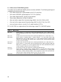
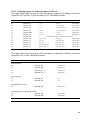
The following courses are available on TIMA or from EDU in your local OLC:
Table 1: Current training
Course Name
Course No.
Format
Length
Location
Alpha Architecture Concepts
EY-I156E
EY-K725E
CBI
1 day
OLC
TIMA
DEC/VAX7000/10000 System Maintenance, level 1
EY-I882E
CBI
1 day
OLC
EY-N402E
CBI (PC)
Futurebus+ Concepts
EY-F479E
CBI
1 day
OLC/TIMA
DSSI Concepts
EY-9823E
IVIS
.5 day
OLC
SCSI Concepts
EY-9900E
Book
.5 day
OLC
TIMA
2.1.1 Training notes:
1.
The prerequisites for this training are VAX6000 level 1, plus 1 years experience.
2.
I’ve included the DSSI and SCSI courses as these systems are starting to appear in
DSSI based clusters.
3.
Since none of these courses includes any "hands on", I would recommend that you get
some OJT by doing an installation or two with someone who is trained. If possible, do
this before your first fault call.
4.
For engineers who have done one of the above courses, but have not been able to "fill
in the gaps" from experience, I have prepared a 1 day seminar. Let me know if you’re
interested.
2.1.2 HOST Training
In addition to the above the following lecture/lab course is currently (Feb-95) available from
HOST Computer Systems (a DIGITAL Franchisee):
Course name: VAX 7000 Systems; course number: M379.
2
2.2 Documentation
The following manuals are available on Fiche and TIMA. A selection of these manuals can
also be found in the Welwyn Technical Library. Some are grouped into kits. The Hardware
User Information kit and the Installation kit are supplied with each system, so you should
find these manuals on site.
The kits are listed in the first table. The next 3 tables list individual manuals for DEC
7000/10000, DEC/VAX 7000/10000 and VAX 7000/10000. In each case the 7000 (only) manuals are listed first. The last table lists DEC/VAX 10000 (only) manuals. Where the part
number is listed as E*, the * = K for hardcopy (TIMA) or P for fiche).
2.2.1 DEC/VAX 7000/10000 Manual Kits
•
DEC7000 AXP/VAX7000 Hardware User Information Kit , EP-7001B-DK-002, (Fiche)
Contains: Operations Manual , EK-7000B-OP-002 and Basic Troubleshooting Manual , EK-7000B-TS-002.
•
DEC7000 AXP/VAX7000 Installation Kit , EP-7000B-DK-002, (Fiche)
Contains: Site Preparation guide , EK-7000B-SP-002 and Installation Guide , EK700EB-IN-002.
•
DEC10000 AXP/VAX10000 Installation Kit , EP-1000B-DK-001, (Fiche)
Contains: Site Preparation Guide , EK-1000B-SP-002 and Installation Guide , EK100EB-IN-002.
•
DEC10000 AXP/VAX10000 System Hardware User Information Kit , EP-1001B-DK-002,
(Fiche)
Contains: Operations Manual , EK-1000B-OP-002 and Basic Troubleshooting , EK1000B-TS-002.
2.2.2 DEC7000/10000 Manuals
•
DEC7000 AXP Pocket Service Guide , EK-7700A-PG-001, (TIMA)
Contains: Registers, addressing, some console commands, testing, FRUs, controls
and indicators, errors, LFU and ROM information.
•
DEC7000/10000 KN7AA CPU Technical Manual , EP-KN7AA-TM-001, (Fiche)
Contains: In depth information on 21064 chip, cache, LSB, console, registers, PALcode, VMS and OSF support, initialisation and error handling for AXP CPU module.
•
DEC7000/10000 AXP Technical Bulletin No 1, E*-70TBA-T1-A01, (TIMA/Fiche)
Contains: Update information to accompany the release of OpenVMS AXP V1.5.
Covers installation, booting and CPU setup.
3
•
DEC7000/10000 AXP Technical Bulletin No 2, E*-70TBA-T2-A01, (TIMA/Fiche)
Contains: Update information to accompany the release of DEC OSF/1 AXP V1.3.
Covers booting, using VET and servicing the MS7BB.
•
Alpha AXP Systems Handbook , (Sales Library)
Customer book telling all about Alpha AXP. Some interesting stuff on 7000/10000
and other AXP systems. Also covers the chip, the architecture, and some new
network and storage products.
•
KN7AA CPU Installation Card , EK-KN7AA-IN-001. (TIMA)
A quick guide to installing or replacing a KN7AA (DEC 7600/10600) CPU module.
•
KN7AB CPU Installation Card , EK-KN7AB-IN-001. (TIMA)
A quick guide to installing or replacing a KN7AB (DEC 7700/10700) CPU module.
•
KFMSB Adapter Installation guide , EK-KFMSB-IN-A01. (Library)
Describes how to install and test the DSSI I/O adapter, KFMSB.
•
KZMSA Adapter Installation guide , EK-KXMSX-IN-001. (TIMA)
Describes how to install a SCSI I/O adapter (KZMSA). Also some general SCSI
notes.
2.2.3 DEC/VAX 7000/10000 Manuals
•
DEC7000 AXP/VAX7000 Basic Troubleshooting , EK-7000B-TS-002, (TIMA)
Contains: Power up and boot flows, self test info., SHOW and TEST commands,
indicators. Written for operators.
•
DEC7000 AXP/VAX7000 Console Reference Manual , E*-70C0B-TM-002, (TIMA/Fiche)
Contains: Console hardware, console interface, console commands.
•
DEC7000 AXP/VAX7000 Installation Guide , EK-700EB-IN-002, (TIMA)
Contains: Installing system and expander cabinets, connecting Ethernet, FDDI,
DSSI and CI, powering up and testing.
•
DEC7000 AXP/VAX7000 I/O System Technical Manual , EP-7010A-TM-001, (Fiche)
Describes LSB I/O subsystem in depth, including discussion of IOP module, DWLMA
(LAMB) module and DWLAA (FLAG) module.
•
DEC7000 AXP/VAX7000 IPB , EK-DV700-IP-A01, (TIMA)
Contains: Illustrated Parts Breakdown (like the old days!).
•
DEC7000 AXP/VAX7000 Operations Manual , EK-7000B-OP-002, (TIMA)
Contains: Description of systems, options, controls and indicators, booting, some
console commands and LFU information.
•
DEC7000 AXP/VAX7000 Platform Service Manual , E*-7000A-SV-001, (TIMA/Fiche)
Contains: Configuration rules, FRU removal and replacement, FRU list.
4
•
DEC7000 AXP/VAX7000 Removable Media Install Guide , E*-TFRRD-IN-001, (TIMA/Fiche)
Describes installing and testing a TF85 or RRD42 in a system or expander cabinet.
•
DEC7000 AXP/VAX7000 Site Preparation Guide , EK-7000B-SP-002 (TIMA)
Contains: Cabinet size and weight, floor space, environmental and power requirements.
•
DEC7000 AXP/VAX7000 System Service Manual , E*-7002B-SV-002, (TIMA/Fiche)
Contains: Replacing/adding CPUs and memories, CPU setups, using the LFU.
•
DEC7000/10000 AXP/VAX7000/10000 Systems Overview , EK-71XEA-OV-A01, (TIMA)
Compares the 4 systems and briefly describes each. Also describes documentation.
•
DEC7000 AXP/VAX7000 Technical Bulletin No 3, E*-70TBA-T3-A01, (TIMA/Fiche)
Contains: Update information to accompany the release of the KA7AB and KN7AB
CPUs. Covers upgrading, new registers and servicing KFMSB and MS7AA-FA options.
•
BA654, Disk PIU Installation Guide , EP-BA654-IN-001, (Fiche)
Describes installing and testing a DSSI disk PIU in a system or expander cabinet.
•
BA655, SCSI Disk and Tape PIU Installation Guide , EP-BA655-IN-001, (Fiche)
Describes installing and testing a SCSI disk and tape PIU in a system or expander
cabinet.
•
DWLMA XMI PIU Installation Guide , E*-DWLMA-IN-001, (TIMA)
Describes installing and testing an XMI PIU in a system or expander cabinet.
•
DWMVA VME Adapter Installation Guide , E*-DWMVA-IN-002, (TIMA)
Describes installing and testing a VME Adapter (DWMVA) in a 6000 or 7000/10000
system
•
H7263 Power Regulator Installation Card , EK-H7263-IN-001, (TIMA)
A quick guide to installing or replacing an H7263 (48v) Regulator.
•
MS7AA Memory Installation Card , EK-MS7AA-IN-001, (TIMA)
A quick guide to installing or replacing MS7AA memory modules.
•
MS7AA Memory Technical Manual , EP-MS7AA-TM-001, (Fiche)
Contains: In depth information on memory controller, organisation and transactions, registers, self test and errors.
•
MS7AA-FA Memory Module Service Manual , EK-MS7AA-SV-A01, (TIMA/Fiche)
Contains: How to identify and replace a failing SIMM.
5
2.2.4 VAX 7000/10000 Manuals
•
VAX7000 Pocket Service Guide , E*-7000A-PG-001, (TIMA/Fiche)
Contains:Registers, addressing, some console commands, testing, FRUs, controls
and indicators, errors, LFU and ROM information.
•
VAX7000 Advanced Troubleshooting , E*-7001A-TS-001, (TIMA/Fiche)
Contains: Powerup and self test with LEDs and console display, diagnostics, parse
trees and PSU info. Written for engineers.
•
VAX7000/10000 Technical Bulletin Number 4, EK-70TBA-T4.
Contains: Register and installation information for KA7AC CPU.
•
VAX7000/10000 KA7AA CPU Technical Manual , EP-KA7AA-TM-001, (Fiche)
Contains: In depth information on NVAX+ chip, cache, LSB, console, registers,
initialisation and error handling for VAX CPU module.
•
KA7AA CPU Installation Card , EK-KA7AA-IN-001. (TIMA)
A quick guide to installing or replacing a KA7AA (VAX 7600/10600) CPU module.
•
KA7AB CPU Installation Card , EK-KA7AB-IN-A01. (TIMA)
A quick guide to installing or replacing a KA7AB (VAX 7700/10700) CPU module.
•
KA7AC CPU INSTALLATION CARD, EK-KA7AC-IN-A01. (TIMA)
A quick guide to installing or replacing a KA7AC (VAX 7800) CPU module.
•
DWMBB VAXBI PIU Installation Guide , EK-DWMBB-IN-001, (Library)
Describes installing and testing a VAXBI PIU in a system or expander cabinet.
•
VMS V5.5-2 7000/10000 CPUs Upgrade and Installation Supplement, AA-PRAHA-TE,
(TIMA)
Contains: Startup, Shutdown and Backup procedures.
•
OpenVMS V6.0 7000/10000 CPUs Upgrade and Installation Supplement, AA-PVXTATE, (TIMA)
Contains: Startup, Shutdown and Backup procedures.
2.2.5 DEC/VAX10000 Manuals
•
DEC10000 AXP/VAX10000 Site Preparation Guide , EK-1000B-SP-002, (TIMA/Fiche
[See kits])
Contains: 4 and 5 cabinet systems, dimensions and weights, space, power and
environmental requirements.
•
DEC10000 AXP/VAX10000 Installation Guide , EK-100EB-IN-002, (TIMA/Fiche [See
kits])
Contains: Assembly of cabinets, connection of FDDI, Ethernet, DSSI and CI, powering up and testing.
6
•
DEC10000 AXP/VAX10000 Operations Manual , EK-1000B-OP-002, (TIMA/Fiche [See
kits])
Contains: Description of systems, options, controls and indicators, booting, some
console commands and LFU information.
•
DEC10000 AXP/VAX10000 Basic Troubleshooting , EK-1000B-TS-002, (TIMA/Fiche
[See kits])
Contains: Power up and boot flows, self test info., SHOW and TEST commands,
indicators. Written for operators.
•
DEC10000 AXP/VAX10000 System Service Manual , E*-1002A-SV-001, (TIMA/Fiche)
Contains: Replacing/adding CPUs and memories, CPU setups, using the LFU.
•
VAX10000 Pocket Service Guide , E*-1000A-PG-001, (TIMA/Fiche)
Contains: Registers, addressing, some console commands, testing, FRUs, controls
and indicators, errors, LFU and ROM information.
•
VAX10000 Advanced Troubleshooting , EP-1001A-TS-001, (Fiche)
Contains: Powerup and self test with LEDs and console display, diagnostics, parse
trees and PSU information. Written for engineers.
3 Descriptions of Systems
The basic building block for all the 7000 and 10000 systems is a single system cabinet called
the Laser Platform. Most 7000s consist only of this cabinet, although an expander cabinet
can be added. 10000s use the same system cabinet along with 1 or 2 expander cabinets and
1 or 2 battery cabinets. The basic Laser Platform is described first.
3.1 Laser Platform
3.1.1 Logic
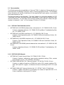
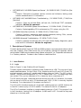
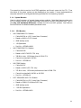
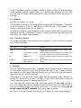
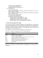
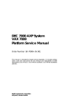
Refer to Figure 1, Laser Platform BLock Diagram .
The basic system interconnect is called the Laser System bus or LSB. This runs on a 9 slot,
double sided backplane. On the LSB sit CPUs, Memories and the I/O port (IOP). Each CPU
and each memory consists of 1 module and therefore takes up 1 slot. The IOP is also 1
module. The minimum configuration is 1 CPU, 1 memory and 1 IOP. The remaining 6 slots
can contain CPUs, up to a maximum of 6, or memories, up to a maximum of 7.
The IOP has 4 ports (aka. hoses) and each can connect to an XMI or Futurebus+. At present
this can be up to 4 XMIs or up to 3 Futurebuses and 1 XMI. (1 XMI is currently required
for booting). For a description of Futurebus+ see Section 5.
The IOP to XMI interface consists of a single XMI module known as a LAMB. Another slot
in the XMI is taken up by a CLOCK module. This leaves 12 slots for I/O adapters.
The IOP to Futurebus+ interface is a single module known as a FLAG. This occupies 1 slot
in the Futurebus+, leaving 9 for I/O adapters. (LAMB and FLAG? - Sounds like they were
dreamt up in the local pub!)
7
A TF85 (for VAX systems) or RRD42 (for DEC systems) can be fitted, as an optional load
device. They connect to the XMI via a KFMSA or KZMSA. Figure 1 shows some XMI
adapters, for a full list see Section 4, XMI Supported Options .
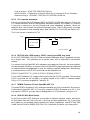
3.1.2 Packaging
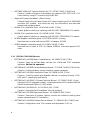
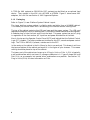
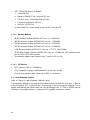
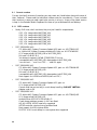
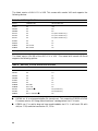
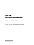
Refer to Figure 2, Laser Platform System Cabinet Layout .
The Laser platform system cabinet is slightly wider and taller than a VAX6000 cabinet.
This means you cannot install one in an existing line of VAXes without moving them.
The top of the cabinet contains the LSB card cage and the power system. The LSB card
cage has a backplane, which is double sided, in the centre (sometimes called a centreplane).
4 modules plug in from the front and 5 from the back. The power system has up to 3 plug
in regulators at the front and an A/C input box and power distribution at the back.
Also in the top are the Operator Control Panel (OCP) and, behind that the Cabinet Control
Logic (CCL) module. The latter provides an interface for the OCP, console and power control
logic. The TF85 or RRD42, if present, resides next to the OCP.
In the centre on the cabinet is the Air Mover (or fan to you and me). This draws in air from
the top and bottom of the cabinet and expels it in the region of your trousers. This means
nothing should be placed on top of the cabinet.
The lower part of the cabinet can house up to 4 Plug-In Units or PIUs. A PIU is basically
a self-contained box which can have I/O, storage or batteries in it. Figure 2 shows XMI and
Disk PIUs, as an example, but several other combinations are possible. See Section 3.3,
Plug In Units (PIUs) for more information on PIUs.
8
Figure 1: Laser Platform BLock Diagram
C
P
U
C
P
U
/
M
E
M
C
P
U
/
M
E
M
C
P
U
/
M
E
M
C
P
U
/
M
E
M
C
P
U
/
M
E
M
M
E
M
M
E
M
LSB
Hose 2
Hose 0
Hose 3
I
O
P
Hose 1
LAMB
FLAG
CLOCK
CI
CIXCD
NI
DEBNA
DSSI
KFMSA
DEFAA
X
M
I
See
Note 1
F
U
T
U
R
E
B
U
S
TF85
NOTES:
1. XMI = 14 slots. Futurebus+ = 10 slots
9
Figure 2: Laser Platform System Cabinet Layout
F
I
L
T
E
R
S
TF85
C
P
U
OCP
C
P
U
C
P
U
C
P
U
or
or
or
48v
48v
48v
M
E
M
M
E
M
M
E
M
Reg
Reg
Reg
L
D
C
C
C
L
M
E
M
A/C
I/P
Box
Laser System Bus
Power System
Power System
Air Mover
XMI PIU
XMI
Reg
I
O
Power
Distribution
C
P
U
C
P
U
or
or
or
M
E
M
M
E
M
M
E
M
Laser System Bus
Air Mover
Disk PIU
XMI
Reg
C
P
U
Disk
Another PIU
XMI PIU
Disk
Futurebus+
Disk
Disk
or
(See note 1)
Storage
Disk
Disk
XMI
FRONT
REAR
NOTE 1: XMI PIU needs full depth of cabinet for cable access
3.1.3 Power
Everything on the Laser Platform runs on 48v DC. The LSB modules have DC to DC converters onboard which provide the required logic voltages. Each PIU has its own regulator(s)
which generate the required internal DC voltages from the 48v input. The one exception is
the battery PIU which uses 48v directly, as does the air mover.
The 48v is provided by up to three 240v AC to 48v Regulators (H7263). The cabinet requires
3 phase mains input, 1 phase supplying each regulator. A fully configured cabinet will run
with 2 regulators, thus 3 provides N + 1 redundancy. Most systems seem to come with just
1 regulator, which makes the platform a single phase load. This may mean moving the
regulators (and batteries, if fitted) around to balance loads in multiple system installations.
See Advanced Troubleshooting Manual, appendix B, for how to calculate when a second
regulator is required. ("Base system" = 1 CPU, 1 Memory, 1 IOP, 1 XMI, 1 DEMNA and 1
regulator). See Section 3.3.6, Battery PIU for battery information.
Note that, as the cabinet does not have a traditional power controller, there are no switched
or unswitched 240v AC outlets. This means a separate socket has to be found for the console.
10
The console is able to monitor the H7263 regulators and the air mover via the CCL. Thus
the status of the power system can be displayed on the console. Future implementations
may even extend to errorlog packets being provided for the Operating System!
3.1.4 System Modules
Here is a brief summary of current Laser system modules. Note that there are two sorts
of CPU Module, one for the VAX7000/10000, and one for the DEC7000/10000 AXP. This is
the only real hardware difference between the VAX and AXP systems. See Platform
Service Manual for detailed module placement rules.
3.1.4.1 CPU Modules
•
•
•
•
VAX 7600/10600 CPU Module:
+
Called KA7AA or LNP (Laser Neon Processor)
+
Based on NVAX+ CISC chipset
+
4MB backup cache
+
~40 Specmarks
+
Part No. = E2045-AA/AB
VAX 7700/10700 CPU Module:
+
Called KA7AB
+
Based on NV5 CMOS-5 CPU chip
+
138 MHz clock, ~50% faster than KA7AA CPU
+
Cannot be mixed with KA7AA
+
Part No. = E2058-AA
VAX 7800 Module:
+
Called KA7AC
+
Based on NVAX v5-2 CPU chip
+
171 MHz clock, ~30% more performance than KA7AB CPU
+
Cannot be mixed with KA7AA or KA7AB
+
Part No. = E2059-AA
DEC 7600/10600 AXP CPU Module
+
Called KN7AA or LRP (Laser Ruby Processor)
+
Based on 21064, EV4 Alpha RISC chip
+
4MB backup cache
+
~150-200 Specmarks
+
Part No. = E2040-AA/YA
11
•
•
DEC 7700/10700 AXP CPU Module
+
Called KN7AB
+
Based on 21064A, EV4_5 Alpha RISC chip
+
275 MHz clock, ~50% faster than KN7AA
+
Cannot be mixed with KN7AA
+
Part No. = E2057-AA
Primary (boot) CPU must reside in slot 0 (LHS, front) of LSB
3.1.4.2 Memory Modules
•
64 MB Memory Module (MS7AA-AA), Part no. = E2043-AA
•
128 MB Memory Module (MS7AA-BA), Part no. = E2043-BA
•
256 MB Memory Module (MS7AA-CA), Part no. = E2043-CA
•
512 MB Memory Module (MS7AA-DA), Part no. = E2046-AA
•
2 GB Memory Module (MS7AA-FA), Part no. = ?????-?? (has SIMMs)
•
16 MB BBU Memory Module (MS7BB-AA), Part no. = E2049-AA, for Prestoserve support on DEC OSF/1 AXP systems
•
One memory module must reside in slot 7 (next to IOP) of LSB
3.1.4.3 IOP Module
•
IOPC module, Part no. = E2044-AA
•
Only 1 allowed, must be in dedicated slot 8 (LHS, rear) of LSB
•
Up to 4 hose (actually flat!) cables out to XMI or Futurebus+
3.2 Laser Expander Cabinet
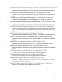
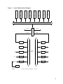
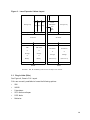
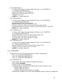
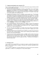
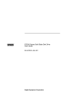
Refer to Figure 3, Laser Expander Cabinet Layout
The expander cabinet is the same as the system cabinet without the CPU bits. It has no
LSB card cage or OCP. In place of the LSB card cage, 2 more PIUs can be installed. Due to
weight and cabling restrictions these can only be storage PIUs. A TF85 or RRD42 may be
fitted as in the system cabinet. A maximum of 2 expander cabinets is allowed.
12
Figure 3: Laser Expander Cabinet Layout
C
C
L
48v
48v
48v
Reg
Reg
Reg
Storage only
Power
Distribution
Storage only
A/C
I/P
Box
Storage PIU
Power System
Power System
Air Mover
Storage PIU
Air Mover
Another PIU
Another PIU
XMI
XMI or BI
or
or
Storage
Storage
or
or
Battery
Battery
Another PIU
Another PIU
Futurebus+
Futurebus+
or
or
Storage
Storage
(See note 1)
(See note 1)
FRONT
REAR
NOTES: 1. XMI, BI and Battery PIUs use the full depth of the cabinet.
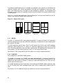
3.3 Plug In Units (PIUs)
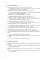
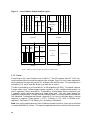
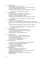
See Figure 4, Generic PIU Layout
PIUs are currently available to house the following options:
•
XMI
•
VAXBI
•
Futurebus+
•
SCSI disks and tapes
•
DSSI disks
•
Batteries
13
The cabinet space filled by a PIU is known as a quadrant (’cos 4 can fit in the bottom of a
cabinet). However, XMI, VAXBI and battery PIUs take up 2 quadrants (1 front and 1 rear)
each. This means that only 2 of these PIUs can be fitted in a cabinet. The Futurebus+ and
Storage PIUs only take up 1 quadrant and thus 4 can be fitted in the system cabinet and 6
in the expander.
Each PIU is briefly described below. Most configuration rules are mentioned here, but for
the full story see the Platform Service Manual.
Figure 4: Generic PIU Layout
Reg B
A
_____
_____
_____
_____
_____
_____
_____
2 x Disk
_____
3x
12v
Batts
2 x Disk
_____
2 x Disk
PSU
I/O type PIU
PSU
SCSI PIU
DSSI PIU
Battery PIU
3.3.1 XMI PIU
The XMI PIU houses an XMI card cage and regulators. It requires 2 (lower) PIU quadrants
to allow cable access to the rear of the XMI backplane. A maximum of 2 per cabinet and 4
per system is allowed.
The XMI backplane has 14 slots. Slots 7 and 8 contain the CLOCK and LAMB modules,
leaving 12 slots available for I/O. There is no restriction regarding I/O slots, as in the 6000
XMI, since the arbitration logic has been removed from the backplane and placed on the
clock module. The first option must go in slot 1 or 14 to terminate the bus.
See Section 4, XMI Supported Options for details on currently supported options.
3.3.2 VAXBI PIU
Only supported on VAX7000/10000 systems.
The VAXBI PIU houses 1 or 2 VAXBI card cages and regulators. It requires 2 (lower) PIU
quadrants to allow cable access to the rear of the VAXBI backplanes. A Maximum of 1 per
cabinet and 3 per system is allowed. It must be in same cabinet as XMI PIU, XMI on LHS,
VAXBI on RHS (from front).
The VAXBI backplanes have 6 slots each. Slot 6 contains the XBIB module, leaving 5 slots
for I/O (10 slots total if both cardcages fitted). Note: XBIA+ module must reside in slot 1 of
XMI.
See Section 4.2, BI Supported Options for details on currently supported options.
14
3.3.3 Futurebus+ PIU
Only supported on DEC7000/10000 systems.
The Futurebus+ PIU houses a Futurebus+ card cage and regulators. It occupies 1 (lower,
rear) PIU quadrant. A maximum of 2 per cabinet and 3 per system is allowed (1 XMI must
be present).
The Futurebus backplane has 10 slots. Slot 5 contains the FLAG module, leaving 9 slots
for I/O.
See Section 5 for a discussion of the Futurebus+ itself.
3.3.4 SCSI Disk and Tape PIU
Only supported on DEC7000/10000 systems.
The SCSI disk and tape PIU houses any combination of 3.5" disk and tape drives and 5.25"
disk drives. It occupies 1 (any) PIU quadrant. A maximum of 2 in the system cabinet and
4 in the expander is allowed.
This PIU contains 2 vertical sections (called shelves!) Each shelf has 7 slots for disks or
tapes. 3.5" devices, RZ26-VA or TLZ06-VA, use 1 slot. 5.25" devices, RZ73-VA, use 3 slots.
To satisfy airflow requirements, the PIU is mounted upside-down if fitted in the top of an
expander cabinet.
3.3.5 DSSI Disk PIU
The DSSI disk PIU houses 1 to 3 disk "bricks". Each brick contains 2 x 5.25" disks (EG:
RF73). It occupies 1 (any) PIU quadrant. A maximum of 2 in the system cabinet and 4 in
the expander is allowed. To satisfy airflow requirements, disk bricks are installed starting
closest to the blower and working down (or up). Also, the PIU is mounted upside-down if
fitted in the top of an expander cabinet.
3.3.6 Battery PIU
The battery PIU houses 1 to 3 battery blocks. Each block contains 4 x 12v batteries. 1
block is required for each 48v regulator. This PIU requires 2 (lower) PIU quadrants due
to it’s size and weight. A maximum of 1 per cabinet is allowed. If the 48v regulators are
reconfigured for phase balancing (see Section 3.1.3, Power ), then the batteries must also be
reconfigured. See Platform Service Manual for more details.
The batteries are used as a UPS rather than BBU. They supply power to everything in the
cabinet and provide ’ride-through’ for short duration power outages. On a fully configured
7000 system they provide a UPS for 10 minutes. On a 10000 system special half-width
battery cabinets are supplied, containing sufficient battery PIUs to provide a UPS for 1
hour.
15
3.4 Who’s who of 7000/10000 systems
This table lists the 7000 and 10000 systems currently available. The following naming and
numbering conventions are used:
•
DEC means Alpha AXP system based on RISC CPU (KN7Ax)
•
VAX means VAX/VMS system based on CISC CPU (KA7Ax)
•
7xxx means departmental, typically single cabinet
•
10xxx means datacentre, at least 4 cabinets
•
x6xx and xx6xx means first chip technology, (NVAX+ for VAX, EV4 for AXP)
•
x7xx and xx7xx means second chip technology, (NV5 for VAX, EV4_5 for AXP)
•
xxnx and xxxnx, where n can be 1 to 6, means number of CPUs
EG: A VAX 7610 is a single cabinet, first technology, single CPU, VAX/VMS system.
Table 2: Who’s who
DEC 76n0
System cabinet. 1 to 6 AXP CPUs, rated at 180 Specmarks each. Up to 14 GB of memory.
Runs OpenVMS AXP and DEC OSF/1. Options include: Expander cabinet for more I/O, storage
or UPS.
DEC 77n0
As DEC 76n0, but with 50% faster CPUs. Needs OpenVMS AXP V6.1 or DEC OSF/1 V3.0.
DEC 106n0
System cabinet + expander cabinet + 2 battery cabinets. 1 to 6 AXP CPUs, rated at 200
Specmarks each. Up to 14 GB of memory. N + 1 power system and UPS (2 x battery cabs)
standard. Runs OpenVMS AXP and DEC OSF/1. Options include: Another expander cabinet
for even more I/O or storage.
DEC 107n0
As DEC 106n0, but with 50% faster CPUs. Needs OpenVMS AXP V6.1 or DEC OSF/1 V3.0.
VAX 76n0
System cabinet. 1 to 6 VAX CPUs, rated at 40 Specmarks each. Memory limited by VMS (512
MB with v5.5, 2 GB with v6.x.) Can be upgraded to DEC 76n0. Runs OpenVMS VAX. Options
include: Expander cabinet for more I/O, storage or UPS.
VAX 77n0
As VAX 76n0, but with 50% faster CPUs. Needs OpenVMS VAX V6.1
VAX 106n0
System cabinet + expander cabinet + 2 battery cabinets. 1 to 6 VAX CPUs, rated at 40 Specmarks each. Memory limited by VMS (512 MB with v5.x, 3.5 GB with v6.x.) N + 1 power system
and UPS (2 x battery cabinets) standard. Can be upgraded to 106n0. Runs OpenVMS VAX.
Options include: Another expander cabinet for even more I/O, storage.
VAX 107n0
As VAX 106n0, but with 50% faster CPUs. Needs OpenVMS VAX V6.1
16
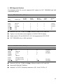
4 XMI Supported Options
The following tables list current supported XMI options for DEC 7000/10000 and VAX
7000/10000 systems.
Table 3: DEC 7000/10000 - XMI Options
Adapter type
Max
per XMI
(OVMS)
CI
2
DEMFA
FDDI LAN
4
4
4
8
1.4 [0514]
DEMNA
NI LAN
4
4
4
8
8.02 [0802]
KDM70
RA/TA/ESE
3
12
3
6
3.00 [1E11]
KFMSB
DSSI
6
6
SCSI
4
6
Option
CIXCD
!
#
KZMSA $
!
"
#
$
Max per
System
(OVMS)
Max per
XMI (OSF)
Max per
System
(OSF)
1
Min
firmware
rev
1.0 [0111]
"
1.0
8
8
4.6
Must be CIXCD-AC (T2080-YA). Note, different ucode for AXP and VAX.
Figures in [ ] show how revision appears in SHOW CONFIG display.
Needs console V3.2 and OVMS AXP V6.1. Not supported on DEC OSF/1?
DEC 7000/10000 only, no VAX equivalent
Table 4: VAX 7000/10000 - XMI Options
Option
Adapter type
Max per XMI
Max per System
Min firmware rev
CI
4
10
70.00 [4611]
DEMFA
FDDI LAN
4
7
1.4 [0514]
DEMNA
NI LAN
4
16
8.02 [0802]
DWMBB
BI
1
3
DWMVA
VME bus
KCM44
CSS high end tape
KDM70
RA/TA/ESE storage
3
12
DSSI
5
12
CIXCD
!
KFMSA
!
"
#
"
#
3.00 [1E11]
5.06 [A2A6]
Must be CIXCD-AC (T2080-YA). Note, different ucode for AXP and VAX.
Must be KFMSA-BA (T2036-Ax)
Assumes 1 x CIXCD. Otherwise, maximum = (25 - No of CIXCDs) / 2
17
4.1 Unsupported XMI options
The following XMI options are not supported on DEC/VAX 7000/10000 systems. Be careful
if upgrading from a 6000 to a 7000, you cannot tranfer these modules.
Option
Adapter type
Module
Comment
CIXCD
CI
T2080
Use CIXCD-AC (T2080-YA)
DWMBA
BI
T2012
Old BI adapter, use DWMBB
DWMUA
Unibus
KFMSA-AA
DSSI
Mythical XMI to Unibus adapter?
T2036
Old DSSI adapter, use KFMSA-BA
4.2 BI Supported Options
The following options are currently supported on VAX7000/10000 systems running OpenVMS V6+. The BI is not supported on DEC7000/10000 systems.
•
DMB32, async. and printer ports only
•
DRB32
•
KRB01 - special encryption module, as used by Camelot
•
Nothin’ else!
4.3 Unibus Support
Don’t even think about it!
5 Futurebus+
5.1 Concept
The Futurebus+ is "a high-performance, asynchronous bus designed by the IEEE 896 committee to allow scalable, technology-independent protocols for many generations of computer
architectures". This means it’s truly open and not based on any particular vendor’s existing
products. It has the following features:
•
High throughput: 750 MB/sec for 64-bit mode, 1.5 GB/sec for 128-bit mode
•
64 bit address space
•
Technology, architecture and vendor independence
•
Data Integrity ensured by superior electrical characteristics
•
Wide industry support
To support all this openness, many different aspects of bus protocol have to be defined. To
simplify matters and ensure compatibility between different products, these definitions are
grouped into "profiles". The following profiles are currently specified:
Profile A: The general purpose, cache coherent CPU environment. (IE: A system bus).
Profile B: The I/O bus noncoherent environment. (IE: An I/O bus).
Profile F: A bus for high-performance packet-mode processors.
18
On DEC 7000/10000 systems Futurebus+ Profile B is used as an I/O bus. A brief description
of the hardware involved is given below. For a detailed explanation see the DEC 7000
AXP/VAX 7000 I/O System Technical Manual. For more on concepts do CBI (see Section 2.1,
Training ).
5.2 Hardware
See Figure 4, Generic PIU Layout
The Futurebus+ consists of a 10 slot backplane and card cage, plus regulators. These make
up the Futurebus+ PIU. Slot 5 is dedicated to the DWLAA (aka. FLAG) module. If this
module is not present the box will not power up.
The DWLAA provides the interface between the Futurebus+ and the LSB. It contains a hose
interface (to the LSB), a Futurebus+ interface, Futurebus+ arbitration logic plus other logic
required for the Profile B implementation.
5.2.1 Futurebus+ Options
The following table lists current options for the Futurebus+. For more information see Alpha
AXP Systems Handbook.
Interconnect
Vendor
Description
FDDI
DEC
DEFAA, adapter for Fibre Distributed Data Interface (FDDI).
Something to do with networks
HiPPI
Aeon System Inc., Myriad
Logic
Adapter for High Performance Parallel Interface (HiPPI). Used
for storage, computer interconnections and networks.
IPI
GENROCO Inc.
Adapter for Intelligent Peripheral Interface (IPI). Used for disk
storage.
VMEbus
Cable and Computer Technology, Nanotek
Bridge to IEEE VMEbus. Used for analog and disk I/O and
networks
6 Console
DEC/VAX 7000/10000 systems have an "imbedded" console, similar to that of the 6000 series.
At initialisation, the primary CPU "wins" the console RX and TX lines. It loads the console
code (actually an UNIX-based Operating System) from it’s Flash ROM into main memory.
When this runs, you get the >>> prompt.
From now on it’s like any other console, except that the command syntax is different (of
course!) It’s case sensitive, it uses "-" for flags, it’s UNIX! See Pocket Service Guide and
Console Reference Manual for command descriptions.
The Flash ROM also contains other code. (EG: ucode patches, PALcode). Any changes to
this or the console code require a complete reload of the Flash ROM. This is achieved using
the Laser Firmware Update (LFU) utility. See Section 7. In a multi-CPU system, do not
use the console UPDATE command until you’ve read this section.
See Section 14, Known Features, Restrictions and Problems for known console problems
19
6.1 Current versions
Current (and old) versions of consoles you may meet are listed below along with some of
their "features". Please read the individual release notes for more details. I have included
their locations in case you need a particular version in a hurry. A copy of the latest version
is kept in the Datadoc Media Cupboard for those of you at Newmarket and Welwyn.
6.1.1 DEC versions
•
Really OLD ones, don’t use these, they are just listed for completeness:
V2.1,
V2.4,
V2.5,
V3.0,
V3.1,
V3.2,
•
LFU
LFU
LFU
LFU
LFU
LFU
image
image
image
image
image
image
called
called
called
called
called
called
AXP7000_V04
AXP7000_V06
AXP7000-V07
AXP7000_V08
AXP7000_V09
AXP7000_V0A
DEC 7000/10000 V4.0
CD: Alpha AXP System Firmware Update V2.9, part no: AG-PTMWL-BE
or: Alpha AXP System Firmware Update V3.0, part no: AG-PTMWM-BE
LFU image called AXP7000_V0B or AXP7000_V0C)
PALcode = 5.48-2/1.35-1
1st release to support KN7AB (7700/10700 CPUs) too
Incompatible with AXP7000_V09, downgrade via AXP7000_V0A
">>> set host ... " and ">>> CDP ... " now OK again
•
DEC 7000/10000 V4.1
CD: Alpha AXP System Firmware Update V3.1, part no: AG-PTMWN-BE
LFU image called AXP7000_V0D
PALcode = 5.48-2/1.35-2
Incompatible with AXP7000_V09, downgrade via AXP7000_V0A
Boot support for HSD05 and HSD30 (but not CDP)
•
DEC 7000/10000 V4.2
CD: Alpha AXP System Firmware Update V3.2, part no:
LFU image called AXP7000_V0E
Console code has serious bug in crash dump handling. DO NOT INSTALL
Adapter code is OK
•
DEC 7000/10000 V4.3
CD: Alpha AXP System Firmware Update V3.3, part no: AG-PTMWQ-BE
LFU image called AXP7000_V0F
Available from VESDAT::DISK$PUBLIC:
Crash dump problems present in V4.2 are fixed
HSJ40, HSD30, HSD05 now fully supported
HSC95 controller startup timing problem fixed
Boot support for 4GB+ system disks
DIGITAL UNIX crash dump to a non-system disc supported
20
•
DEC 7000/10000 V4.4
CD: Alpha AXP System Firmware Update V3.4, part no: AG-PTMWR-BE
LFU image called AXP7000_V10
Available from VESDAT::DISK$PUBLIC:
Required for OVMS V7.0 and UNIX V4.0
No bug fixs since V4.3
update -e no longer supported
•
DEC 7000/10000 V4.5
CD: Alpha AXP System Firmware Update V3.5, part no: AG-PTMWS-BE
LFU image called AXP7000_V11
Available from VESDAT::DISK$PUBLIC:
Supports OVMS V7.0 and UNIX V3.2d or V4.0
PALcode = V5.53-3 for VMS, V1.45-2 for OSF (they mean UNIX!)
May not see devices on HSJ40s in single CI path Cluster (see Blitz TD# 2015)
update -e no longer supported
•
DEC 7000/10000 V4.6
CD: Alpha AXP System Firmware Update V3.6, part no: AG-PTMWT-BE
LFU image called AXP7000_V12
Supports OVMS V6.2-1H3 or V7.0 and UNIX V3.2g or V4.0
PALcode = V5.53-3 for OVMS, V1.45-2 for UNIX
The single patch HSJ failure has been corrected
update -e no longer supported
•
DEC 7000/10000 V4.8
CD: Alpha AXP System Firmware Update V3.7, part no: AG-PTMWU-BE
LFU image called AXP7000_V14
Supports OVMS V6.2-1H3 or V7.0 and UNIX V3.2g or V4.0a
PALcode = V5.56-3 for VMS, V1.45-2 for UNIX
update -e no longer supported
6.1.2 VAX versions
•
Really OLD ones, don’t use these, they are just listed for completeness:
V1.2, LFU image called VAX7000_V02
V2.4, LFU image called VAX7000_V04
V2.6, LFU image called VAX7000_V06
•
VAX 7000/10000 V3.0
Major release, fixes many problems and adds new features
Boot command changed
Console CD part no: AG-PQW1D-BE
Available from VEX::REPOSITORY$:[NEON_RELEASED.CONSOLE.V3_0]
V30_RELEASE_NOTES.PS
V30_RELEASE_NOTES.TXT
VAX7000_V07.SYS (MOP-loadable LFU image)
Available from TIMABOX TOOLS as "VAX 7000/10000 Console CD (Rev D) (FIRMWARE)"
21
•
VAX 7000/10000 V3.1
Minor upgrade to V3.0, not released on CD
Controller-based shadow set problem (ds.. in BOOTDEF_DEV) fixed
Console now recognises all EFxx disk drives
Available from PROXY"fal$access"::LASER_CONS_PUBLIC:[PUBLIC]
VAX7000_V08.SYS (MOP-loadable LFU image)
•
VAX 7000/10000 V3.2
Minor upgrade to 3.2, not available on CD (after all)
Contains fix for HSJ-40 reboot problem, plus fixes in V3.1
Needs patch for "single path HSJ40" problem
Available from PROXY"fal$access"::LASER_CONS_PUBLIC:[PUBLIC]
VAX7000_V07_2.SYS (MOP-loadable LFU image, CPU code only)
•
VAX 7000/10000 V3.3
Last version of 3.*, not available on CD
Contains fix for "single path HSJ40" problem, so patch no longer required
Contains fix for dual-path system disk shutdown problem, new variable: BOOT_
ALT
Available from PROXY"fal$access"::LASER_CONS_PUBLIC:[PUBLIC]
VAX7000_V07_3.SYS (MOP-loadable LFU image, CPU code only)
VAX_V33_RELEASE_NOTE.TXT
•
VAX 7700/10700 V1.0
1st version of console for KA7AB (77x0/107x0 CPUS)
Image not released to field, may be seen on early modules
LFU image called VAX7700_V01
Cannot be used for KA7AA (76x0/106x0 CPUS)
•
VAX 7700/10700 V1.1
1st release of console for KA7AB (77x0/107x0 CPUS)
Contains fix for PUST failures in multiple CPU systems
LFU image called VAX7700_V02
Cannot be used for KA7AA (76x0/106x0 CPUS)
Console CD part no: AG-Q8GNB-BE
•
VAX 7000/10000 V4.0
Major release, fixes a bunch of StorageWorks and other problems
Same version supports 76xx and 77xx systems
Console CD part no: AQ-PQW1E-BE
LFU image called VAX7000_V09
Available from VESDAT::DISK$PUBLIC:
•
VAX 7000/10000 V4.1
1st release of console for KA7AC (78x0 CPUs)
Supports 2 x 2GB memory modules, but..
SHOW POWER does not work properly on 76x0 and 77x0 systems
Also, OVMS logs power problems, so..
Do Not Install unless have 78x0 CPUs or 2GB memories
Adapter code is OK
22
Console CD part no: AQ-PQW1F-BE
LFU image called VAX7000_V0A
Available from VESDAT::DISK$PUBLIC:
•
VAX 7000/10000 V4.2
V4.1 power problems fixed
New environmental variable, COMPAT_MODE, allows VAX VMS V5.5-2 to run on
7600s (in addition to 7800s)
New environmental variable, BOOTVAX_COMPAT, allows reboots from initial boot
device or BOOTDEF_DEV
Console CD part no: AQ-PQW1G-BE
LFU image called VAX7000_V0B
Available from VESDAT::DISK$PUBLIC:
VAX7000_V0B.EXE (local bootable LFU image)
VAX7000_V0B.SYS (MOP bootable LFU image)
VAX7000_V0B_REL_NOTE.TXT (Release Notes - text)
VAX7000_V0B_REL_NOTE.PS (Release Notes - Postscript)
7 Laser Firmware Update (LFU) utility
This one utility is used for loading all firmware on the Laser platform. At present this
means any loadable firmware for LSB and XMI options. Ideally, when a new console version
is released, it comes on a CD which contains the latest version of the LFU along with the
latest versions of all the firmware. This prevents the compatibility problems that previous
ucode update utilities have suffered from.
For a description of the various ways of booting the LFU, see Section 7.2
Once the LFU is booted, it displays a menu of the following options:
Function
Description
Display
Displays the system’s configuration table
Exit
Return to >>> (system reinitialises)
List
Lists the device types and firmware revisions supported by this version of LFU
Modify
Modifies port parameters and device attributes
Show
Displays device mnemonic, hardware and firmware revisions
Update
Replaces existing firmware with loadable data image
Verify
Compares loadable and existing device images
? or Help
Displays menu
So you can see what’s in the system, compare it with what’s on the CD and update if
necessary. See Pocket Service Guide and/or console Release Notes for exact use of LFU
commands.
23
The latest version of VAX LFU is V0B. This comes with console V4.0 and supports the
following devices:
Table 5: VAX7000_V0B LFU devices and revisions
Device
Hardware Rev.
CD Firmware Rev.
CIXCD
All
72.0
DEMFA
All
2.0
DEMNA
All
8.3
KA7AA
All
4.2 (76xx console rev.) †
KA7AB
All
4.2 (77xx console rev.) †
KA7AC
All
4.2 (78xx console rev.) †
KCM44
All
3.1
KDM70
All
4.4
KFMSA
A01 to A04
5.1
KFMSA
B01 to B04
5.6
†Latest (Apr 96) console revision = 4.2
The latest version (Oct 96) of the AXP LFU is V14. This comes with console V4.8 and
supports the following options:
Table 6: AXP7000_V14 LFU devices and revisions
Device
Hardware Rev.
CD Firmware Rev.
CIXCD
All
7.0
DEFAA
All
1.0
DEMFA
All
2.1
DEMNA
All
8.3
KCM44
All
3.1
KDM70
All
4.4
KFMSB
Rev. B01
1.0
KFMSB
Rev. C02
2.4
!
KN7AA
All but rev.K
KN7AB
All
KZMSA
Rev. F and above
!
"
24
4.8 (console rev)
"
4.8 (console rev)
5.6
KN7AA rev. K is not supported after 2.4 (console rev). This causes the "ERROR: KN7AA
Firmware revision 0.0 Image failed checksum" message when the LFU boots.
KZMSA rev. E or earlier does not have ucode loadable via LFU. It will work OK with
old (rev. 3.15) ucode but see Section 13, FCOs .
7.1 Important considerations when using the LFU
The LFU makes upgrading firmware on Laser platform devices fairly easy and safe, provided
a few points are taken into account:
1.
On most of the modules the firmware is stored in a Flash ROM. This is a serial device
which has to be completely loaded every time, in one go. Therefore, the LFU update
must not be interrupted. If it is, the module can be left in a completely unuseable and
unrecoverable state. If this happens it has to be replaced. This implies a very slight
risk to every update due to power failure etc.
2.
Upgrading the firmware on the CPU module(s) requires special care. This firmware
includes parts which affect the Operating System as well as the hardware. This means
the revisions of software and hardware must be taken into account. EG: You could
change the firmware to fix a hardware bug and then find OSF/VMS won’t boot due to a
PALcode mismatch (an extreme case to make the point!) The SID also gets changed.
3.
In a multi-CPU system, all CPUs must have the same firmware revision. There is a
console UPDATE command which copies the contents of the Flash ROM from one CPU
module to another. However, this does not aways work between different revisions. So
if you’re changing the firmware revision always use the LFU.
4.
Point 3 becomes especially interesting when a CPU module in a multi-CPU system has
to be replaced. The new one may be at a different firmware revision to the originals.
Therefore, the LFU will be required to bring them all into line. Therefore, the correct
version of LFU must be available on site.
5.
The CPUs also have an EEPROM. The image in this has to match the Flash ROM.
You have to "build" the EEPROM every time the Flash ROM is updated, (see console
Release Notes).
6.
Some other modules have a SEEPROM (serial EEPROM). At console V3.0, this also has
to be "built" after a console upgrade. Various serial number type information may be
required, (see console Release Notes).
7.
If you skip versions when upgrading consoles, you must read the release notes for the
skipped versions to be aware of all changes. Also, some versions are only compatible
with the next, and so may not boot if there is a gap. This applies to downgrading too;
you may have to step up or down through each version. The bottom line, as always, is:
read the release notes!
7.2 Booting the LFU
If your system has a console RRD42, you can boot the console or update CD from that (see
below), if not you need to find an Infoserver. See Section 8.1, Booting a 7000/10000 from a
CD in an Infoserver .
If your "console or update CD" is on tape, see Section 8.2, Putting a service on the Infoserver
system disk , or Section 7.2.3, Booting the LFU from another system .
25
7.2.1 Booting the LFU from the console RRD42
This is the simplest method, but is restricted to DEC 7000/10000s as (normally) only these
have RRD42s. As the "Alpha AXP Systems Firmware Update CD" has code for all Alpha
systems on it, you have to specify the bootfile.
1.
Load the Update CD into the console RRD42
2.
At DEC 7000 >>> boot -flag 0,80 dkxn.n.n.n.n
do >>> show device kzmsa* to find device name
3.
After the initial bootstrap has loaded, you are asked for the Bootfile
4.
Bootfile: [DEC7000]AXP7000_Vnn.EXE
nn = version number. There is a separate [DEC10000]AXP10000_Vnn.EXE file
For V2.5 and earlier the file has a .APB extension
5.
The LFU banner and menu appears
7.2.2 Booting the LFU from a local disk
The AXP LFU can be booted from a local disk on a DEC 7000, assuming it’s running OpenVMS AXP, like this:
1.
With the system up, copy AXP7000_Vnn.EXE to SYS$SYSTEM
2.
Shut down the system and boot from the system disk with boot flags 0,80
3.
At the Bootfile: prompt, type AXP7000_Vnn.EXE
4.
The LFU banner and menu appears
The VAX LFU can be booted from a local disk on a VAX 7000, like this:
1.
With the system up, choose the local disk. Do not use the system, or any other currently
bootable disk, as the pointer to VMB will be lost.
2.
Copy VAX7000_Vnn.EXE to DISK:[DIR] (your chosen disk and directory)
3.
Use Writeboot to write the boot block to point to the LFU file:
$ MC Writeboot
Target system device (and boot file if not VMB.EXE): DISK:[DIR]VAX7000_Vnn.EXE
Enter VBN of boot file code (default is 1): (take default)
Enter load address of primary bootstrap in HEX (default is 200: (take default)
4.
Shut down the system
5.
Boot your chosen disk:
boot -flags 0,0,0 DISK (EG: DUA2.0.0.4.0)
6.
26
The LFU banner and menu appears
7.2.3 Booting the LFU from another system
The latest Infoservers do not have a system disk so the procedures described in Section 8.2
are no use. The only way to load a "network copy" of the LFU in this situation, is from
another system somewhere on the network:
1.
Copy the appropriate .SYS file (VAX7000_Vnn.SYS or AXP7000_Vnn.SYS) into the
MOM$LOAD directory of the chosen system. You will find this directory on any system
which is setup to downline load Decservers etc.
2.
Check that the system has "service enabled", using NCP> SHOW CIRCUITS.
3.
Boot just as you would if the image were on an Infoserver:
>>> boot -flags 0,0,0 exa0 -file VAX7000_Vnn ; for VAX systems (nn = version)
or
>>> boot -flags 0,0,0 exa0 -file AXP7000_Vnn ; for AXP systems (nn = version)
4.
The LFU banner and menu appears.
Obviously, you could always use this method and ignore the Infoserver. However, remember
that you may need the LFU at any time, and it is arguably less likely to be lost from an
Infoserver.
8 Infoserver
As a TF85 or RRD42 is only an option on the Laser platform, most have no console media.
Therefore, booting the LFU and initial S/W installation has to be done from an Infoserver.
The Infoserver is basically a small VAX with 1 or 2 CD readers, connected to Ethernet. It
"serves" the CDs to other systems on the network. Thus, you can boot your 7000/10000 from
it’s console CD in the Infoserver.
NOTE: The Infoserver must be running kernel software version 2.2 or later. Do INFOSERVER> show server, to check.
To load an image not on a CD see Section 8.2, Putting a service on the Infoserver system
disk and Section 7.2.3, Booting the LFU from another system .
8.1 Booting a 7000/10000 from a CD in an Infoserver
8.1.1 Booting the VAX LFU
Here is an example of loading the LFU for a VAX 7000/10000 from a CD in an Infoserver.
1.
Load CD into Infoserver
2.
At VAX7000 >>> boot -flags 0,0,0 exa0 -file ISL_LVAX_V07
exa0 is ethernet device (fxa0 for DEMFA (FDDI) adapter)
ISL_LVAX_V07 is the name of the file to be loaded and is different for each version.
It decodes as Initial System Load, Large VAX, version 7. Unfortunately the version
number is not the same as the console version number (V3.0 in this case), and not
always the same as the LFU version number either (see Release Notes)
3.
If all goes well, the "Network Initial System Load Function" banner appears, and a
menu of functions is displayed.
4.
Select 3, "Choose Service"
27
5.
A number of services will be displayed, depending on how many Infoservers are present
and how many services they offer
6.
Select the one called "VAX7000_V07"
7.
The LFU is loaded and it’s banner and menu appears
8.
If you wanted to load something else, you could choose a different service at step 6.
8.1.2 Booting OpenVMS VAX Standalone BACKUP
Here is an example of loading Standalone BACKUP from the OpenVMS VAX distribution
CD.
1.
Load CD into Infoserver
2.
At VAX7000 >>> boot -flags 0,0,0 exa0 -file ISL_LVAX_060
See release notes for specific file name, which must be in uppercase
3.
After the ISL has loaded, select function 3, "Choose Service"
4.
Select the VMS service you want (VMS060 in this example)
5.
The "OpenVMS VAX ..." banner appears
8.1.3 Booting the AXP LFU
In this case an initial system loader is not used, and the LFU image is loaded directly.
1.
Load CD into Infoserver
2.
At DEC7000 >>> boot exa0 -file AXP7000_Vnn
nn = version number. Device = ffa0 for DEFAA (FDDI) adapter
3.
LFU banner and menu appears
8.1.4 Booting OpenVMS AXP Standalone BACKUP
Same as OpenVMS VAX, except different ISL filename:
1.
Load Open VMS AXP Distribution CD into Infoserver
2.
At DEC7000 >>> boot exa0 -flags 0,0 -file APB_015
3.
"Choose Service" etc....
8.2 Putting a service on the Infoserver system disk
Sometimes we don’t have the image we want to load, via an Infoserver, on CD. This is often
the case with the latest console version, which can be obtained from ENET long before the
CD is available. The way round this is to put the image on the Infoserver’s System disk and
make it look like just another service. For this you need a terminal connected to Infoserver
to act as a console. You also need access to a VAX somewhere on the same network as the
Infoserver. (See Datadoc - VAX 6000 section).
The following example creates a new version of VAX LFU (the procedure is the same for
AXP LFU).
1.
28
Copy Saveset of VAX 7000/10000 console CD (from TIMA) to tape.
2.
At the Infoserver: †
•
Create partition on system disk for console image:
INFOSERVER> Create partition dk1:VAX7000_Vnn blocks NNNN †
INFOSERVER> Show partition dk1:
•
Create temporary service for this partition:
INFOSERVER> Create service temp1 for dk1:VAX7000_Vnn
3.
At the VAX:
•
Use BACKUP to unpack the saveset into SYSMAINT.
•
Check for "client software":
$ Show device dad,
•
If not present load it:
$ @sys$startup:ess$startup client
$ Show device dad
Now have DAD0
•
"Bind" partition on infoserver disk to "client software":
$ mcr ess$ladcp bind/write_enable temp1
This creates logical unit DAD1
•
Mount it:
$ mount/for DAD1
$ show device dad
Now have DAD0 and DAD1
•
Copy image to partition:
$ Copy/contig VAX7000_Vnn.sys dad1:*.*
$ dism dad1
4.
Back at infoserver:
•
Delete temporary service:
INFOSERVER> Delete service temp1
•
Enable partition to BOOT:
INFOSERVER> Set partition dk1:VAX7000_Vnn mop enable
INFOSERVER> save
INFOSERVER> sho partition dk1:
5.
LFU image is now on infoserver and can be booted over the network.
† nn = version, NNNN = size of VAX7000_Vnn.SYS (in blocks)
29
8.2.1 Booting the LFU from the Infoserver system disk
Once the LFU image is on the Infoserver system disk (see Section 8.2), it is booted as follows.
This is slightly different to booting from the console CD in that the Initial System Loader
is not used. Because the image was "mop enabled" it can be loaded directly:
>>> boot -flags 0,0,0 exa0 -file VAX7000_Vnn ; for VAX systems (nn = version)
>>> boot -flags 0,0,0 exa0 -file AXP7000_Vnn ; for AXP systems (nn = version)
You don’t get the menu of services (as per ISL_VAX etc.), The LFU banner and menu appear
directly.
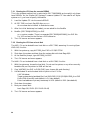
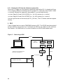
9 RDC
Figure 5 shows how to connect a 7000/10000 system to RDC. The MDS01 baud rates should
be set to 9600 for the console line (T switches) and 1200 for the modem line (M switches).
See Datadoc - VAX 6000 section, for more information on MDS01 and modem setup.
Figure 5: Connecting to RDC
BC22F*
$
MDS01
(rear view)
* BC22F can be replaced with
a BC16−E and H8571−D
A1
B1
A2
B2
H8575−A
BC22F
17−01364−02
MODEM
VAX/DEC 7000/10000
Console
(MMJ)
RDC
30
10 Parts and FRUS
The following tables are from the Product Service Plans. If you can’t find a part here look
in the IPB.
Table 7: Laser LSB and Platform parts
Part Number
Mnemonic
Description
E2045-AA
E2045-AB
E2045-YA
E2058-AA
E2040-AB
E2040-YA
E2057-AA
E2044-AA
E2043-AA
E2043-BA
E2043-CA
E2056-AA
E????-??
54-21718-01
E2049-AA
TK85-BX
RRD42-AA
12-35173-01
12-39865-01
30-33796-02
30-33798-02
30-35143-01
54-19089-01
54-20300-01
54-20306-01
70-28574-01
KA7AA
KA7AA
KA7AA
KA7AB
KN7AA
KN7AA
KN7AB
VAX (NEON) 7600 CPU Module (for 7610 -> 7640)
VAX (NEON) 7600 CPU Module (for 7650 -> 7660)
VAX (NEON) 10600 CPU Module
VAX 7700/10700 CPU Module
DEC (Ruby) 7600 CPU Module (Old, 180 Mhz)
DEC (Ruby) 7600/10600 CPU Module (200 Mhz)
DEC 7700/10700 CPU Module
IOPC Module
64Mb Memory Module
128Mb Memory Module
256Mb Memory Module
512Mb Memory Module
2Gb Memory Module
64 Mb SIMM for MS7AA-FA
16Mb BBU Memory
Tape Drive
CDROM (AXP only)
Main Blower Assembly
Replacement battery for MS7BB
Bulk Regulator (Europe,GIA,Japan)
AC Input Box (Europe & GIA)
DC Dist. Assy (Subrack)
TF85 Controller
Cabinet Control Logic
Operator Control Panel
Centerplane/Cardcage
MS7AA-AA
MS7AA-BA
MS7AA-CA
MS7AA-DA
MS7AA-FA
MS7BB-AA
H7263
CCL
OCP
LSB
Table 8: XMI PIU parts
Part Number
Mnemonic
Description
T2020-00
T2027-00
T2028-AA
T2018
T2029-AB
T2029-AC
T2030-YA
T2036-AA
T2080-YA
30-36009-01
30-36010-01
70-30396-01
DEMNA
DEMFA
DWLMA
DWVMA
KZMSA
KFMSB
CLOCK
KFMSA-BA
CIXCD-AC
XMI to NI Controller
XMI to FDDI Controller
LAMB Module (Laser to XMI)
XMI to VME adapter
XMI/SCSI Controller (AXP only)
XMI/DSSI Controller (AXP only)
ARB (Clock & Arbitration)
XMI/DSSI Controller (VAX only)
XMI/CI Controller
Module B (PWR), XMI regulator
Module A1 (PWR), XMI regulator
XMI Backplane Assy
31
Table 9: Futurebus+ PIU parts (AXP only)
Part Number
Mnemonic
Description
B2003-AA
B????-??
30-36009-01
30-36011-01
54-21662-01
DWLAA
DEFAA
FLAG module (Laser to FBUS+ )
FBUS+ to FDDI
Module B (PWR), Fbus+ regulator
Module A2 (PWR), fbus+ regulator
FBUS+ Backplane Assy
Table 10: Disk PIU parts
Part Number
Description
RZ35-E0
54-19110-01
54-19119-01
54-20868-01
54-21664-01
54-21664-02
70-28814-01
RZ35 Disk Drive (SCSI)
RZ73 Module
RF73-EA ECM Module
Local Disk Convertor
Disk Control Panel (DSSI)
Disk Control Panel (SCSI)
RF73/RZ73 HDA
Table 11: Battery PIU parts
Part Number
Description
12-36168-02
Battery
12-39982-01
Fuse [LPN-RK-90]
17-03421-01
Battery Sensor Cable
The following parts are all cables:
17-03492-01
"A" Intermediate
17-03493-01
"B" or "C" Intermediate
17-03494-01
"A" to CEAG (Green Label)-Laser
17-03494-02
"B" to CEAG (Blue Label) -Laser
17-03494-03
"C" to CEAG (White Label)-Laser
17-03496-01
Balancing Cable - Blazer Expander
17-03496-02
Balancing Cable - Blazer Expander
17-03497-01
"A" to CEAG (Green Label)-Blazer CPU
17-03497-02
"B" to CEAG (Blue Label) -Blazer CPU
17-03497-03
"C" to CEAG (White Label)-Blazer CPU
17-03497-04
"A" to CEAG (Green Label)-Blazer Exp
17-03497-05
"B" to CEAG (Blue Label) -Blazer Exp
17-03497-06
"C" to CEAG (White Label)-Blazer Exp
Table 12: Miscellaneous Cables
Part Number
Description
12-13756-A8
17-00811-03
17-02382-02
17-02382-07
DSSI ground cable (between cabs)
Console Terminal Cable
9’ External DSSI Cable
DSSI Brick Jumper Cable
32
Table 12 (Cont.): Miscellaneous Cables
Part Number
Description
17-03085-01
17-03085-02
17-03118-01
17-03118-02
17-03119-01
17-03120-01
17-03121-01
17-03122-01
17-03123-01
17-03124-01
17-03126-01
17-03127-01
17-03153-01
17-03153-03
17-03162-01
17-03163-01
17-03164-01
17-03201-01
17-03202-01
17-03348-01
17-03415-01
17-03416-01
17-03417-01
17-03418-01
17-03419-01
17-03420-01
17-03422-01
17-03423-01
17-03424-01
17-03443-01
17-03444-01
17-03445-01
17-03448-01
17-03505-01
17-03508-01
17-03511-01
17-03531-01
17-03532-01
17-03533-01
IO HOSE Cable, Long "114 †
IO HOSE Cable, Short "53 †
48V LSB PWR (GRY)
48V LSB PWR (YEL)
48V Pwr/Sig PIU (4:1 Cable)
Sig OCP/CCL
Sig CCL/LSB Bulk
Sig LSB Bulk/LSB BP
Sig LDC/CCL
Sig AC/CCL
48V Pwr/Sense Blower
Pwr 48V AC to LDC
SCSI Brick Jumper Cable
9’ External SCSI Cable
Sig X-PIU
48V Pwr X-PIU
Pwr +5/+12 LDC/TF
DEC Power Bus
Pwr Dist X-PIU
Sig, DSSI/Bulk {TK85}
SCSI Bus Cable
+5vb Jumper X-PIU
RF73 Signal Cable
LDC Power Cable
LDC Signal Cable
RF73 Power Cable
Signal & Power Cable
DCP to B/H
DSSI Bus Cable
Pwr LDC/Bulk
Sig LDC/Bulk
PWR, LDC to RRD42
DSSI Bus TF to B/H
5V VTERM Power Cable
48V CEAG to B/H
Expander Cab to Host OCP
SCSI RRD to B/H
Storme Signal & Power Cable
Bulkhead to XMI Signal Cable
† Some 3M cables were mis-labelled 17-03058-xx
11 Diagnostics and testing
There are no loadable diagnostics for DEC/VAX 7000/10000 systems. There is no VAX
Diagnostic Supervisor for the VAXes. All diagnostic testing is done using the console and
onboard ROM based diagnostics.
At initialisation the console displays a matrix telling you who’s there and who’s passed their
selftest, similar to the VAX 6000 series. From the >>> prompt you can then run various
tests. You can also ">>> set host" to some adapters, to run the onboard RBD tests.
33
The Pocket Service Guide explains some console commands for testing. For more detail see
Console Reference Manual. For LEDs and selftest failures see Advanced Troubleshooting
Manual.
Testing under the Operating System can be done with UETP for VAX systems and VET for
DEC systems. See Section 14.2.4, DEC Verifier and Exerciser Tool (DEC VET) .
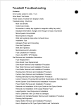
12 Troubleshooting Tips
If you replace a CPU, in a multi-CPU system, use the LFU not the console UPDATE command to update the console firmware. See Section 7.
If you replace an H7263 regulator, don’t forget the 5 delay upon inserting the new one. See
Installation Card.
If you’re planning a console upgrade make sure a spare CPU is available nearby. Console
upgrades can go wrong and most customers don’t like having to wait for a replacement from
Nijmegen.
Each VAX CPU has a System Indentification Register (SID), which contains CPU type and
ucode information. When you replace a CPU, or upgrade the ucode, the value of this register
will change. This is, of course, supposed to happen, but beware of customers with "SID
locked" applications. (See Datadoc - VMS section for description of SID).
If you replace or upgrade a CPU in a DEC/VAX 10000 system, make sure environmental
variable "system_variant" is set to 1 afterwards.
If you replace or install a CIXCD-AC in a DEC/VAX 7000/10000 system, remember that it
may come with the "wrong sort" of ucode installed. IE: It has AXP ucode and you put it in
a VAX, or vice versa. In this case the console will not recognise the option and ">>> show
device" will display it as "unknown0". You can still load the correct ucode from the LFU,
using the following command.
Function? update unknown0
You will be asked for the device name, type CIXCD
34
13 FCOs
Table 13: FCO summary for DEC/VAX/7000/10000
FCO
SB#
Description
7xxx-F001
747
Removing C49 from blower servo stops it self-destructing
Quick Check: blowers with serial nos. above 675 or marked with green dots are
OK
Kit: EQ-01656-01
7xxx-F002
751
New door catches + air pressure switch on CCL bypassed
Quick check: door catches at rev D01 and CCL at rev J03 or greater are OK
Kit: EQ-01666-01
7xxx-F003
758
Various power parts and cables upgraded to ensure FCC Compliance. Spares
only affected
Quick check: see FCO document
Kit: EQ-01675-xx
7xxx-F004
763
New VAX CPU modules remove memory interleaving restriction and fix Cache
ECC problems
Quick check: CPU modules (E2045-AA) at rev P07 or higher are OK
Kit: EQ-01673-01
!
7xxx-F005
—
New CCL module fixes potential power up problem due to C14 reversed. Only
7xx0s from Ayr between weeks 21 and 31 (1994) are affected
Quick check: See FCO document or Section 14.3, Other Goodies
Kit: EQ-01708-01
10xxx-F001
763
Same as 7xxx-F004, but for 10xxx systems
KFMSB-O001
773
New adapter supports LFU and does 2 byte write properly
Quick check: KFMSB-AA (T2029-AC) is rev C02 or higher
Kit: EQ-01709-01
KN7AA-O001
773
New DEC CPU fixes memory interleave and cache ECC problems
Quick check: CPU is E2040-YA at Rev E01 or higher
Kit: EQ-01694-01
KN7AA-F002
765
Rev E* LAMB module (T2028-AA) allows byte addressing for BI and VME options
on DEC 7000/10000. Spares only affected
Quick check: T2028-AA = rev E*
Kit: EQ-01686-01, not available in Europe
KZMSA-F001
757
New KZMSA for DEC 7000 systems allows onsite ucode update (via LFU)
Quick check: KZMSA modules (T2029-AB) at rev F are OK
Kit: EQ-01674-01
!
"
"
The FCO originally said rev P06 modules were OK, but some turned out to have bad TAG
RAMs. See FCO document for full details, but basically, modules below rev P06 need
replacing, those at P06 may need replacing and those above P06 do not need replacing.
Beware, this FCO appeared on SB 776, called 7xxx-F004 and 10xxx-F001. These are
the numbers for the VAX CPU FCO!!
35
14 Known Features, Restrictions and Problems
14.1 Console issues
These are some of the known console issues which might touch an MCS engineer. There are
others, so always read the release notes for the version of console you are dealing with.
14.1.1 BOOTDEF_DEV restrictions
VAX7000/10000 V1.2 console hangs during boot if string for BOOTDEF_DEV is greater
than 96 characters. V2.4 supported up to 127 (thus allowing 6 devices to be specified),
other environmental variables were limited to 31 characters. With V3.* we are back to only
4 devices being allowed in BOOTDEF_DEV string. If >>> set bootdef_dev ... command
exceeds one line don’t include carriage return, just overtype.
14.1.2 DEC7000 console cannot find an OSF/1 dump partition
This problem occurs when OSF/1 is configured to place the dump partition on a disk drive
other than the system disk. OSF/1 uses the console’s device driver to write the dump, but
the console only knows about the boot device. Thus OSF/1 displays "can’t open dump device",
and the dump is lost.
The following work-around gets the console to configure a path to the disk containing the
dump partition before it boots OSF/1 from the system disk. It applies to versions V2.5 thru’
V4.1. This example powerup script configures all disks on KZMSA1.
>>> set mode advance
>>> set eeprom script powerup
Script> set mode advance
Script> kn7aa_pwrup
Script> config kzmsa1
Script> set mode basic
Script> ^z
>>>
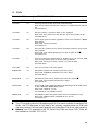
A permanent fix is planned for a future console release.
14.1.3 DEC 7000 consoles and ">>> set host ..." command
Certain versions of DEC 7000 console have trouble with this command:
From V3.0 to V3.2 ">>> set host -dup ..." does not work. (Not sure about earlier consoles).
The ">>> cdp ..." command has to be used to configure DSSI disks.
At V3.2 ">>> set host ..." does not work. (V3.0 and V3.1 are OK). This means devices like
CIXCDs and DEMNAs cannot be tested using RBDs. The only way to test a CIXCD in
loopback mode is with the RBDs so you may have to downgrade the console for this.
Both these problems are fixed at console version V4.0.
36
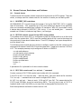
14.1.4 DEC 7000 console V3.2 and OpenVMS AXP V1.5
Depending on CI and disk numbers, OpenVMS AXP V1.5 may not boot after the console
has been upgraded to V3.2 or higher. The fix is to install a patch to OpenVMS before
upgrading the console.
The patch is on the Alpha AXP System Firmware Update CD, and called [DEC7000]AXPAPB01_
015.A. Install it using VMSINSTAL.
14.1.5 HALT-RESTART problem in VAX V2.x and DEC V2.1 consoles
When the AUTO_ACTION environment variable is set to RESTART and the operating systems error-HALTs back to console, the console calls a restart routine stored in the HWRPB.
Unfortunately, the console mishandles the program stack and causes another HALT. The
second HALT, while a restart is in progress, causes a reboot. The reboot can result in the
loss of system crash dumps.
Fixed in VAX 7000 V3.0 and DEC 7000 V2.5 console.
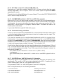
14.1.6 Shadowset booting restrictions
There is a restriction with all VAX7000/10000 V2.* console firmware that when booting from
a controller-based shadow set the physical and virtual unit numbers must be unique. This
restriction is removed with V3.0.
V3.0 uses the mnemonic ’ds’ for controller-based shadow sets and ’du’ for physical drives.
Unfortunately it has another bug which prevents the use of ’ds’ in the BOOTDEF_DEV
string so you cannot setup a V3.0 console to automatically boot from a controller-based
shadow set. Boot nickname files work OK, but this means the system will not come up after
a crash until someone types >>>Boot "nickname". This is fixed in V3.1.
Use of the boot flags for booting controller-based shadowsets also changed between V2.4 and
V3.0. Up to V2.4 the first boot flag only contained the virtual unit number (in HEX) and
a bit to indicate shadow set booting. From V2.6 onwards the first flag also contains the
physical unit number. So...
boot -fl 8DAC,2,0 etc. where DAC = virtual unit no. (3500 in DEC)
now becomes
boot -fl 8DAC0000,2,0 etc. where DAC = virtual unit no. and 0000 = physical unit no.
0.
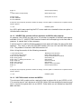
14.1.7 HSC EDC Errors - VAX7000 Console V1.2 Interaction
HSCs which use K.ci1 (HSC70/40/50) can have data buffer descriptor corrupted by V1.2
console code. This results in EDC errors being detected by the HSCs. Temporary fix is to
install following patch, best bet is to upgrade console to V3.0.
This procedure is ONLY for VAX 7000 Systems Console V1.2-1931[A14]
After initing the console, do the following commands:
>>>set mode advanced
>>>set eeprom script powerup
Script> d 27021 49a2108a
Script> d 271a3 49a2108a
#following cmd is advanced
#open eeprom script buffer
#enter deposit cmd
#enter deposit cmd
37
Script> ^z
>>>
>>>show eeprom script powerup
Powerup Script:
d 27021 49a2108a
d 271a3 49a2108a
#close script (control Z)
#print eeprom script
#verify that it is correct
At this point only the primary processor contains the change. Use the update -e command now to update the other
CPUS, if present
>>> init
#initialize system
Any HSCs which were reporting the EDC errors need to be re-booted to clear corruption in
the data buffer descriptor.
14.1.8 VAX/DEC7000 consoles will not auto boot via HSC95s after powerup
At powerup, the HSC95 can take up to 3.5 minutes to complete its selftests and become
available to the CI. VAX/DEC7000 consoles timeout while attempting to auto boot after a
powerup. A manual boot is then necessary.
A workaround is to add the following powerup script which will delay the start of the boot
sequence. This script is valid for DEC7000 console V2.5 thru V4.1 and VAX7000 console
V3.n. The problem is fixed with VAX7000 console V4.0.
After initing the console, do the following commands:
>>>set mode advanced
>>>set eeprom script powerup
Script> set mode advanced
Script> kn7aa_pwrup
Script> echo -n " Waiting 120 seconds..." > tt
Script> sleep 120
Script> echo "done" >tt
Script> set mode basic
Script> ^Z
>>>
#following cmd is advanced
#open eeprom script buffer
#script needs advanced commands
#test memory etc.
#tell operator
#wait 120 seconds
#tell operator
#back to normal commands
#close script (control Z)
At this point only the primary processor contains the change. Use the update -e command now to update the other
CPUS, if present
>>> init
#initialize system
14.1.9 VAX 7000 console revision and HSD30
The minimum VAX console revision required to boot a system disk via an HSD30 is V4.0.
V3.n consoles cannot "see" devices on an HSD30. Before V4.0 was available the workaround
was to connect the system disk via an HSD05. Other disks are not affected as OpenVMS
can see them.
38
14.1.10 VAX 7000 and HSJ40, Single Path Booting Problem
As described in Section 14.1.11, a VAX 7000 will not boot from an HSJ40 disk if one path
to the HSJ40 controller is disabled. Unfortunately, this configuration is needed as a workaround for the HSJ40 "dual receive crash" problem.
The following console patch allows the VAX 7000 to boot over a single path. It should only
be installed on systems that boot from an HSJ40 system disk and have console version V3.24041[A6] . It must be removed when the console is upgraded. (Use >>> build eeprom, to
erase patch).
Execute the following commands to install the patch.
>>> set mode advanced
>>> set eeprom script powerup
Script> set mode advanced
Script> ka7aa_pwrup
Script> echo "Applying single path boot patch to V3.2-4041[A6]" > tt
Script> d -w 2DBA6 2811 -u
Script> d -l 2dbce 05B13511 -u
Script> d -l 2dbd2 B1471350 -u
Script> d -l 2dbd6 42135011 -u
Script> d -l 2dbda A0C401E0 -u
Script> d -l 2dbde CA11DA00 -u
Script> Set mode basic
Script> ^Z
>>> Set mode basic
!
On multi processor systems use this command to update the other CPUs:
P00>>> update ka7aa* -e
!
This message pops out at Initialise time to tell you the patch is being applied.
14.1.11 VAX 7000 fails to reboot from HSJ-40 devices
VAX 7000 V2.X and V3.0, V3.1 consoles don’t handle the virtual circuit with the HSC-40
properly when attempting to reboot. This causes the boot to fail like this:
P00>>>
Booting...
Connecting to boot device dua403.10.0.13.0
Created device: dua403.10.0.13.0
device dua403.10.0.13.0 not found
failed to open dua403.10.0.13.0
P00>>>
The fix is to install VAX7000 Console V3.2. Note a problem still exists when attempting to
SHOW DEVICE or boot a drive with PATH A or B disconnected or disabled from an HSJ40. You must have both paths enabled and connected for the console code to work properly.
Alternatively, see Section 14.1.10.
39
14.1.12 DEC/VAX 7000 MOP booting problem
Current DEC/VAX 7000 consoles cannot handle MOP Protocol V4. If there is a server
anywhere on the network which supports V4 Protocol, the MOP boot may fail. Here is an
example, seen while booting from an Infoserver 1000:
>>>
Booting...
Connecting to boot device exa0
Created device: exa0.0.0.1.0
Requesting MOP Assistance Volunteer.
MOP Assistance Volunteer found.
Loading...
.Retrying MEM_LOAD...Retries exhausted.
bootstrap failure
The following workaround applies to DEC 7000 consoles V3.0 and earlier, or VAX 7000
consoles V3.3 and earlier. This forces the console to request a MOP Protocol V3 boot (which
it can handle).
>>> set mode advanced
>>> set mopv3_boot 1
>>> set mode basic
14.1.13 VAX 7000 MOP boot fails with RRD43
Current VAX 7000 consoles on CD fail to boot from an Infoserver, if the CD drive is an
RRD43. The ISL loads and runs correctly but when a service on the CD is selected the
system halts, thus:
CPU:0 Console entry reason : HALT instruction in kernel mode
Entry PC: 00147691 Entry PSL: 041F0600
boot failure
The failure occurs because the current ISL file (ISL_LVAX_V07) does not work with RRD43s.
OVMS Standalone Backup cannot be booted from CD either (as it uses the same ISL file).
Once OVMS is up however, the RRD43 can be used normally.
The only workaround, at present is to swap the RRD43 for an RRD42. The ISL file should
be fixed in Spring ’95.
Note: This means that some new VAX 7000 systems, as delivered, cannot be booted!
14.1.14 Boot fails due to suspected corrupt EEPROM on VAX 7000
This problem has been seen with V2.4 and V3.2 consoles, but probably applies to others too.
A MOP boot fails thus:
>>> boot -flag 0,0,0 -file VAX7000_V07_3 exa0
Too many strings
Fail to update eeprom env var on CPU 0
40
Environmental variables can still be manually set and the default ">>> boot" will work.
However, there is something wrong with the EEPROM, and this can be fixed with a ">>>
build eeprom"; after this the MOP boot will be ok.
Note: ">>> build eeprom" causes customer environmental variables to be lost so note them
first using ">>> show *" .
14.1.15 TEST DWLMA* fails on VAX 7000s with multiple XMIs
This failure may occur on VAX 7000 systems with 2 x DWLMAs connected as dwlma0 and
dwlma1. When they are both tested together using the above command the diagnostic fails
as it is finishing, thus:
Stopping DWLMA exerciser on dwlma0
Stopping DWLMA exerciser on dwlma1
CPU 0: unexpected exception/interrupt...
[loadza registers...]
Failing FRU: iop0
Catastrophic IO failure, system will be reset
Don’t panic, this is a diagnostic problem (presumably on all current VAX 7000 consoles).
Either test the DWLMAs individually, or move the 2nd hose to IOP slot 3 (makes the 2nd
DWLMA dwlma2). The test will then complete correctly.
14.1.16 HSD05 slow boot + no auto reboot on VAX 7000
Booting from an RZxx device on an HSD05, over 5DSSI is very slow (6 minutes from VMS
banner to next message!). Also, auto reboot fails with the message "Unable to initialise
device...". These problems occur with all V3.* consoles. The following patch can be applied
to fix the reboot problem; there is no fix for the slow boot at present. (No mention of either
of these bugs in the V4.0 release notes - not sure if they’re fixed).
This patch can only be applied to V3.3 consoles and should only be implemented on VAX
7000/10000 systems that have system disks on an HSD05.
Execute the flowing commands to install the patch.
>>> set mode advanced
>>> set eeprom script powerup
Script> set mode advanced
Script> ka7aa_pwrup
Script> echo "Applying HSD05 reboot patch to console" > tt
Script> show device kfmsa*
Script> set mode basic
Script> ^Z
>>> set mode basic
!
!
This message pops out at Initialise time to tell you the patch is being applied.
41
14.1.17 Using wrong LFU can render CPU unusable
You must use the correct LFU for the model being upgraded, See Blitz TD 1858. Basically
for:
DEC7000 Model 700, must use AXP7000_V0B or later
VAX7000 Model 700, must use VAX7000_V08 or later
14.1.18 VAX7000-8XX Initialization problem
At console V4.2, 78x0 CPUs in multiple CPU systems may fail to initialise. Do not replace
CPU, just try again. May be fixed in future console FW release, see Blitz TD 1959.
14.2 Software issues
14.2.1 Supported Versions of Operating Systems
For DEC76x0/106x0:
The minimum supported version of OpenVMS AXP is V1.5
The minimum supported version of DEC OSF/1 is V1.2
For DEC77x0/107x0:
The minimum supported version of OpenVMS AXP is V6.1
The minimum supported version of DEC OSF/1 is V3.0
For VAX76x0/106x0:
The minimum supported version of VAX/VMS is V5.5-2HW (pre-release of V5.5-2)
The minimum supported version of OpenVMS VAX is V6.0
For VAX77x0/107x0:
The minimum supported version of OpenVMS VAX is V6.1
For VAX78x0:
The minimum supported version of OpenVMS VAX is V6.1 (or V5.5-2 with special V4.2
console setup)
42
14.2.2 Operating system .vs. firmware support + PALcode
This table shows which version of console firmware is required for different versions of
OpenVMS AXP and OSF/1, plus PALcode on DEC 7000/10000 systems.
Console Rev
LFU
OpenVMS AXP
DEC OSF/1 AXP
PALcode
2.5
AXP7000_V07
1.5
1.2, 1.3
5.41-5/1.28-9
3.0
AXP7000_V08
1.5
1.3, 1.3A, 1.3B
5.44-1/1.32-3
3.1
AXP7000_V09
1.5
1.3, 1.3A, 1.3B, 2.0
5.47-1/1.34-2
3.2
AXP7000_V0A
1.5, 6.1
1.3, 1.3A, 1.3B, 2.0
5.48-1/1.35-1
4.0
AXP7000_V0B/C
1.5, 6.1
2.0, 3.0
5.48-2/1.35-1
4.1
AXP7000_V0D
1.5, 6.1
2.0, 3.0, 3.1
5.48-2/1.35-2
4.2
AXP7000_V0E
4.3
AXP7000_V0F
1.5, 6.1, 6.2
up to 3.2C
5.48-2/1.35-2
4.4
AXP7000_V10
6.2, 7.0
up to 3.2C, 4.0
5.48-2/1.35-2
4.5
AXP7000_V11
6.2, 7.0
up to 3.2D, 4.0
5.53-3/1.45-2
4.6
AXP7000_V12
6.2, 6.2-1H3, 7.0
up to 3.2G, 4.0
5.53-3/1.45-2
4.8
AXP7000_V14
6.2, 6.2-1H3, 7.0
up to 3.2G, 4.0A
5.56-3/1.45-2
** Don’t install this one, it has some serious bugs **
This table shows which version of console firmware is required for different versions of
OpenVMS VAX on VAX 7000/10000 systems.
Console Rev
LFU
OpenVMS VAX
3.0
VAX7000_V07
5.5-2 to 6.1
3.1
VAX7000_V08
5.5-2 to 6.1
3.2
VAX7000_V07_2
5.5-2 to 6.1
3.3
VAX7000_V07_3
5.5-2 to 6.1
1.0
VAX7700_V01
6.1
1.1
VAX7700_V02
6.1
VAX7000_V09
5.5-2 to 6.2
VAX 76x0 only:
VAX 77x0 only:
VAX76x0 and VAX 77x0:
4.0
VAX76x0 and VAX 77x0 and VAX 78x0:
4.1 †
VAX7000_V0A
5.5-2 to 6.2
4.2
VAX7000_V0B
5.5-2 to 6.2
†Only install if have 78x0 or 2GB Memories - has power bugs. Use V4.2 now
43
14.2.3 VAX 7000 systems may not reboot or write the dump file
VAX 7000 systems using Host Based Volume Shadowing may display the following message
during booting:
"SHADOW-I-VOLPROC, DSAnnn does not contain member named to VMB, Warning system
may not reboot or dump".
If a bugcheck or forced crash occurs the system halts and a system dump is not written.
This problem only occurs if CSCPAT_0269021 (patch including SHDRIVER) is installed. Fix
is to obtain newer version of SHDRIVER from CSC.
14.2.4 DEC Verifier and Exerciser Tool (DEC VET)
This is the Alpha equivalent of UETP. It runs under OpenVMS AXP and DEC OSF/1 operating systems. See DEC 7000/10000 AXP Technical Bulletin No1 for a brief description of
it’s use. See DEC Verifier and Exerciser Tool User’s Guide, AA-PX73A-TE for more details.
DEC VET is included in the OpenVMS and DEC OSF/1 distributions on the Alpha AXP
Systems Firmware Update CD. The following table lists recent versions:
Table 14: DEC VET vs Operating Systems
DEC VET
OpenVMS AXP
DEC OSF/1
FW CD part number
V3.0
V6.1
V3.0
AA-PTMWM-BE
V3.1
V6.1
V3.0,3.1
AA-PTMWN-BE
14.2.5 Corrupt Boot Blocks and WRITEBOOT
During booting 7000/10000 systems get VMB.EXE or APB.EXE from the system disk. The
console bootstrap code finds these files by reading the "Boot Block" (block 0) off the disk.
Two problems can occur here:
1. The files can move if a defragger is run on the system disk.
2. The boot block can fail to get initialised if the system disk is backed up and not restored
properly.
If either occurs the system disk becomes unbootable.
The fix is to run the WRITEBOOT utility which rewrites the Boot Block as shown below.
Example of WRITEBOOT for OpenVMS VAX V6.0:
+
$ RUN SYS$SYSTEM:WRITEBOOT
+
Target system device (and bootfile if not VMB.EXE):? $1$DUA0
+
Enter VBN of boot file code (default is 1): 1
+
Enter load address of primary bootstrap in HEX (default is 200): 200
Example of WRITEBOOT for OpenVMS AXP V1.5:
+
$ RUN SYS$SYSTEM:WRITEBOOT
+
Update VAX portion of boot block (default is Y) : n
+
Update AXP portion of boot block (default is Y) : y
44
+
Enter AXP boot file : dka100:[VMS$COMMON.SYSEXE]APB.EXE
The above will put the required good stuff in block 0 of the system disk. However, you will
notice that OpenVMS has to be up, which could be a bit of a problem if you can’t boot the
system disk! If the problem is not spotted until the system/cluster is all down, one of the
following options may be your only hope:
a. Boot Standalone Backup (from a CD).
b. Load VMB from tape, and then patch registers to boot the system disk (see STARS
article "How to load VMB from a TF85").
c. Move the disk drive to another system.
And then run WRITEBOOT from there.
14.2.6 Mandatory Patch for Cache ECC Errors on VAX7000/10000
The Cache error correction routine for the VAX 7000 and VAX 10000 does not properly
correct cache single bit errors. Temporary fix is to install one of the following patches:
VAXSYSL13_U2055 for VAX/VMS V5.5-2
VAXSYSL01_060 for OpenVMS VAX V6.0
These patches are in "Mandatory Cache ECC Error Handling Kit", CD-ROM part number
AG-PZLBA-BE, and in TIMA. To check if patch is already installed:
$ ANALYZE/SYSTEM
SDA> SHOW SYSLOA
Verify that:
MCHECK1701: X-13A2 (for VAX/VMS V5.5-2)
MCHECK1701: X-16A1 (OpenVMS VAX V6.0)
Note that if customer upgrades VMS from V5.5-2 to V6.0, the old patch will be lost and the
new will have to be installed.
The permanent fix is to do FCO 7xxx-F004.
14.2.7 SCSI Disks and Volume Shadowing with OpenVMS AXP 1.5
SCSI devices connected locally to the same AXP host, should not be included in the same
shadowset. This can cause bugchecks and "other" failures. Fixed in next release, expected
Spring ’94.
14.2.8 OpenVMS VAX V6.1 Power messages at Boot time on VAX 7000
At boot time we now check power on the 7000 and 10000 platforms. There is a problem
in the V6.1 SYSLOA code for VAX 7000 that causes the following error messages, falsely
indicating a power regulator problem.
%POWER-E-BAD, bad R0=00003003
%POWER-I-NOTIFY, central cabinet
%POWER-E-BAD, bad R0=00003003
%POWER-I-NOTIFY, central cabinet
from CTSR$GETC
regulator A event, check errorlog
from CTSR$GETC
regulator B event, check errorlog
These message may repeat several times. There is nothing wrong with the power. Engineering will produce a patch "soon".
45
14.2.9 OpenVMS AXP and DEC7000 Crash Dump Problems
There are two situations on DEC7000 systems running OpenVMS AXP V6.1 which may
cause only partial crash dumps to be written that are no use for analysis:
On systems with large (512MB+) memories, booted from a system disc via the CI, writing
the dump may stop prematurely with "Halt Code 05". This is caused by a bug in PNBTDRIVER.EXE. The fix is to apply the following patch kit:
OpenVMS AXP patchkit, AXPBOOT01_061, available as CSCPAT_2091.
The second problem involves systems booted via DSSI. Here, if a console key is pressed
while the dump is being written, the system may hang. The fix is either not to touch the
console, or to upgrade the console firmware to V4.1. If you can’t wait for V4.1 a "patched"
version of V4.0 is available from:
PROXY"fal$access"::allen_public:[public]AXP7_IPMT_PC.SYS
14.3 Other Goodies
I have assembled the following information on known problems from BLITZs, STARS, Notes
and local knowledge. Some bits are directly quoted, others I have edited (as you can probably
tell!)
14.3.1 DEC/VAX 7000 Air Flow Pressure Switch Causes System Shutdown
Air flow pressure switch on the CCL module (DEC P/N 54-20300-01) can cause the system to
perform intermittent shutdowns due to false air flow faults. An FCO was issued to replace
CCL module (see Section 13). Temporary fix is to jumper out the pressure switch.
14.3.2 Battery wiring on DEC/VAX 10000s
Failure to observe proper polarity when connecting battery wiring can cause severe power
system damage, overheating and emission of smoke. Note that ORANGE wires are POSITIVE (+) polarity and BLUE wires are NEGATIVE (-) polarity. See "DEC 10000 AXP
SYSTEM VAX 10000 INSTALLATION GUIDE" (EK-100EB-IN.002), sections 2.15, 2.16 and
2.17.
14.3.3 CIXCD Microcode on Alpha/VAX VMSclusters
Only the CIXCD-AC (T2080-YA module) is supported with the Laser platform. It normally
comes loaded with VAX compatible ucode (CIXCD.BIN). However, DEC7000/10000 systems
need different ucode that is AXP compatible (CIMNA.BIN). Factory installed options will be
OK, but if you install one you must run the LFU to load the correct ucode. Field spares
could have either ucode on board so be careful.
14.3.4 VAX 7000/10000 CIXCD Write Error Interupt (WEI) Errors
While booting a VAX 7000/10000, VAX-VMS creates two error log entries that are caused
by the CIXCD testing WEI (write error interrupt) logic. The error log entries appear to be
reporting a real error when they are actually reporting a selftest diagnostic activity. If the
errors have the following footprint, you can safely ignore them.
The errorlog entries only occur when the system is being booted
The date is always - 1-JAN-1992 00:00:00.00
46
First errorlog is - ADAPTER ERROR KA7AA-AA
XBER contains - Enable More Protocol & Write Error Interrupt & Error Summary
Second errorlog is - MEMORY CONTROLLER ERROR KA7AA-AA
14.3.5 CCL capacitor backwards
A bunch of systems left AYR between WK21 and WK31 of 1994 with capacitor C14 on the
CCL module reversed. Most of these systems have been traced by DECnumber, so I mention
it here just in case one or two slip through and cause subsequent problems. When the
capacitor fails it will prevent the system from powering up. Thus it’s failure will only show
up when the system is next powered down! Now fixed by FCO 7xxx-F005 (see Section 13).
This is the correct orientation of C14:
TOP
O
C14
AT&T
DC−DC Power
O
O
O
black band this end
OO
Module
Front of cabinet
14.3.6 DEC7000 with >2GB memory, CIXCD, running OpenVMS, may crash
On the DEC7000/10000, the CIXCD does not handle addresses above 2 gigabytes correctly
for a special case. The symptoms are a system crash, with a reference to non-existant
memory.
For systems running OpenVMS with adequate non-paged pool there will not be a problem.
One workaround, therefore, is to ensure that the OpenVMS sysgen parameters are adjusted
to create sufficient non-paged pool to cover the system’s heaviest load periods. Altenatively,
a corrected version of the CIXCD microcode can be obtained from:
PROXY"FAL$ACCESS"::CI_PUBLIC:[PUBLIC]CIMNA_X12.SYS
This is a MOP bootable LFU image containing only the new CIXCD microcode. The corrected
CIXCD microcode will be included in a regular release of the LASER Firmware Update
Utility (LFU) currently targeted for February ’95.
14.3.7 DEMFA Firmware V2.0 and OpenVMS AXP V1.5
The latest DEMFA firmware is V2.0, and spare modules are likely to come with this version.
Unfortunately OpenVMS AXP V1.5 can only recognise DEMFA firmware up to V1.4. So if
you replace a DEMFA, you may have to downgrade it to V1.4 firmware, using the LFU.
14.3.8 DSSI PIU Disk Brick Gotcha
On the front of each DSSI disk brick are two sets of indicator switches, one for each drive.
At first glance they look like LEDs, but in fact they are also pushbuttons. So, if your drive
won’t power up, you probably need to operate the "power" pushbutton. See DEC/VAX 7000
Pocket Service Guide or BA654, DSSI Disk PIU Installation Guide for a full description.
47
14.3.9 EF51R-LA and EF52R-LA Disks VAX 7000/10000 Systems
Early KA7AA/E2045 console code does not support the EF51R and EF52R DSSI drives.
Fixed in version 3.0 of console.
The hole around the Node-ID connector on the EF51R and EF52R drives does not allow the
cable to be installed properly. (You have to "gently push" it).
VMS V5.5-2 does not support ERF (Error Formatter) for the EF51R and EF52R disk drives.
VMS V6.0 does.
14.3.10 KFMSA reports "Invalid Buffer Name" errors on busy VAXes
These errors can be logged in the errorlog of VAX 7000/10000s during heavy I/O activity. At
the same time a message is displayed on the console saying the port will be re-initialised
and all the drives associated with the KFMSA do a mount verification. So far these errors
have only been seen on systems with dual XMIs, fully loaded with KFMSA-BAs.
The fix is new ucode for the KFMSA-BA. However this has not been made available for
general distribution as it does not work on VAX66xx systems. It can only be obtained
directly from Engineering. If your system suffers from these errors contact me, or your local
Support engineer.
14.3.11 KFMSB Cable kit
The XMI backplane to DSSI bulkhead cable kit for a KFMSB (AXP XMI to DSSI adapter) is
different to that for a KFMSA (VAX XMI to DSSI adapter). Use of the wrong one damages
the modules, so be careful when doing an upgrade.
14.3.12 KZMSA and TZ85/6/7s give errors on OSF systems
If tape is written with one record size and read back with a smaller record size, the last
data buffer of the transfer is not returned completely. Problem has been seen with TAR
utility and TAPEX exerciser under OSF V1.3. Only occurs with KZMSA firmware earlier
than X046.
Fix is to upgrade KZMSA to X046 firmware using the LFU. A mop bootable LFU image
(KZMSA_X046.SYS) can be copied from:
PROXY"FAL$ACCESS"::LASER_CONS_PUBLIC:[PUBLIC]KZMSA_XO46.SYS
Note: KZMSA modules at rev. E or earlier do not have firmware loadable via LFU. FCO
KZMSA-F001 would then be required.
14.3.13 KZMSA revision for OSF/ASE
ASE V1.1, an OSF layered product, needs the KZMSA (T2029-AB) to be rev F03 or later.
The installation fails if it is not. If the KZMSA is rev F02 or F02 it can be upgraded by
fitting a new EPROM (23-419E9-00) in E7. If it is rev F01 or earlier it must be replaced.
48
14.3.14 Vital information in Laser Errorlogs
There is a process whereby Operating System errorlog information can be placed in the
EEPROMs of Laser CPUs. These logs (called rather confusingly SDD) are a great help to
the repair centres. This process was not supported by VMS before version 6.0 and OSF/1
version ???. So the message is: include a hardcopy of the errorlog with any CPU module
you return (always a good idea anyway).
14.3.15 LFU Version 5.2 revision reporting
The SHOW command under version 5.2 of the LFU will sometimes incorrectly display the
CPU hardware revision. Ignore this figure, get revision from CPU module. Later versions
of LFU get it right.
14.3.16 Async 05 Machine Checks on Multiple CPU VAX7000/10000s
DSM and other applications may experience Async 05 Machine Checks running in an SMP
environment. Stack frame shows failing opcode of 5D, an INSQTI instruction. Fixed by
V2.6 of VAX7000/10000 console.
14.3.17 MS7AA-FA SIMM isolation on DEC 76/7700 from OpenVMS AXP errorlog
When a memory CRD error is logged for the 2GB array, the error formatter may not give the
information required to identify which SIMM is at fault. A manual procedure for decoding
the errorlog entry and locating the SIMM is described in the MS7AA-FA Memory Module
Service Manual.
14.3.18 VAX 7000 upgrade gotcha
When the VAX 7000 was first announced, the maximum supported number of CPUs was 4
(IE: a 7640). Now 6 CPUs are supported (IE: a 7660). Unfortunately this required a change
to the CPU module, making it a -AB variant. This means upgrading a 7640 to a 7650 or
7660 may mean replacing all the CPUs as only E2045-ABs will work. (E2045-AAs are fine
for 7610s thru 7640s).
14.3.19 DEC OSF/1 AXP PRESTOSERVE memory option MS7BB
This is a 16 MB battery backed up memory which sits in the LSB backplane. It’s onboard
battery will "keep" data for up to 48 hours of power outage. It is used with OSF/1 as a cache
for disk I/O (now you know why it’s got BBU!) and, as this speeds things up a bit, it is also
known as PRESTOSERVE.
Installing and servicing this option is a bit more exciting than ordinary memories, so make
sure you read The DEC OSF/1 guide to PRESTOSERVE (AA-PQT0A-TE), and the MS7BB
section of DEC 7000/10000 AXP Technical Bulletin No2, before you try it.
The DEC7000/10000 implementation consists of an option: DJ-70APS-AA. This includes
the MS7BB-AA, a PAK for the PRESTOSERVE license and installation documentation.
DJ-70APS-AA requires a minimum revision matrix of console, OSF, and CPU module for
system compliance. (To work they mean!) Systems below revision must be upgraded before
the option is installed.
49
Table 15: Minimum system revisions for PRESTOSERVE support
DEC7000-600
DEC10000-600
CPU Module:
E2040-AB Rev A01
E2040-YA Rev C01
PRESTO Memory:
E2049-AA Rev C03
same
Console:
V3.0
same
OSF:
V1.3-4
same
14.3.20 DEC/VAX 7000/10000 Memory interleaving restriction
A problem with the LEVI-A chip on early CPU modules results in the following memory
configurations only being allowed.
•
1, 2 or 4 of the same size modules, up to max of 512 MB
•
1 x 128 MB + 2 x 64 MB modules
•
1 x 256 MB + 2 x 128 MB modules
An unsupported configuration results in the following console message at boot time:
"Invalid memory interleave—boot disallowed".
Fixed on VAX 7000/10000 by FCO 7xxx-F004 (see Section 13). No fix for DEC 7000/10000s
at present.
NOTE: Some VAX 7600 CPU modules (E2045) may not be at the revision they claim to be.
See BLitz TD 1947.
14.3.21 RZ57s on ALPHA platforms
RZ57s on DEC 7000 systems must be rev. D01 (rev. 6000 ucode) or above. Lower revs. can
suffer undetected write faults. An EQ kit has been proposed, but not for an FCO. Customers
are expected to buy it!
14.3.22 RF73s in VAX 7600 SF73LA, cable problem
The flex cable at the rear of the RF73 can get damaged if the drive is positioned too far back
on it’s skid plate. The drive should be mounted using the third set of holes from the front.
14.3.23 VMS gains time
Some VAX 7000 systems experience a problem where VMS system time gains by more the
9 sec per day (the quoted tolerance). This is fixed by a REV N06 KA7AA (E2045-AA) CPU
module. If module can’t be replaced, customer can run a batch job to do SET TIME every
12 hours.
50