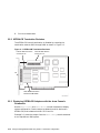
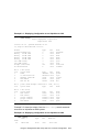
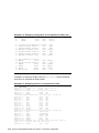
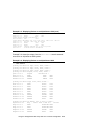
1
TruCluster Software Products
Hardware Configuration Technical Update for
StorageWorks RAID Array 3000
January 1999
Product Version:
TruCluster Production Server
Software Version 1.5 and TruCluster
Available Server Software Version 1.5
Operating System and Version:
Compaq’s DIGITAL UNIX Version
4.0D
This technical update describes how to configure the hardware for the
TruCluster Production Server Software Version 1.5 and TruCluster
Available Server Software Version 1.5 products with a StorageWorks
RAID Array 3000 storage subsystem.
Compaq Computer Corporation
Houston, Texas
© Compaq Computer Corporation 1999
All rights reserved.
The following are trademarks of Compaq Computer Corporation: ALL–IN–1, Alpha AXP,
AlphaGeneration, AlphaServer, AltaVista, ATMworks, AXP, Bookreader, CDA, DDIS, DEC, DEC Ada,
DEC Fortran, DEC FUSE, DECnet, DECstation, DECsystem, DECterm, DECUS, DECwindows, DTIF,
Massbus, MicroVAX, OpenVMS, POLYCENTER, PrintServer, Q–bus, StorageWorks, Tru64, TruCluster,
ULTRIX, ULTRIX Mail Connection, ULTRIX Worksystem Software, UNIBUS, VAX, VAXstation, VMS,
XUI, and the Compaq logo.
Microsoft, Windows, and Windows NT are registered trademarks of Microsoft Corporation. UNIX is a
registered trademark and The Open Group is a trademark of The Open Group in the US and other
countries.
Restricted Rights: Use, duplication, or disclosure by the U.S. Government is subject to restrictions as set
forth in subparagraph (c) (1) (ii).
Compaq Computer Corporation makes no representations that the use of its products in the manner
described in this publication will not infringe on existing or future patent rights, nor do the descriptions
contained in this publication imply the granting of licenses to make, use, or sell equipment or software in
accordance with the description.
Possession, use, or copying of the software described in this publication is authorized only pursuant to a
valid written license from Compaq or an authorized sublicensor.
Compaq conducts its business in a manner that conserves the environment and protects the safety and
health of its employees, customers, and the community.
Contents
About This Technical Update
1 Introducing the StorageWorks RAID Array 3000 Storage
Subsystem
1.1
1.2
StorageWorks RAID Array 3000 General Overview .. . .. . .. . .. .
RAID Array 3000 Restrictions .. . .. . .. . .. . . .. . .. . .. . .. . . .. . .. . .. . .. .
1–1
1–2
2 Using the StorageWorks RAID Array 3000 in a TruCluster
Configuration
2.1
2.2
RA3000 Installation Overview . . .. . .. . .. . . .. . .. . .. . .. . . .. . .. . .. . .. .
Installing and Configuring a TruCluster Configuration with a
StorageWorks RAID Array 3000 .. . .. . .. . . .. . .. . .. . .. . . .. . .. . .. . .. .
2.2.1
Obtaining the Firmware Release Notes .. . .. . .. . . .. . .. . .. . .. .
2.2.2
KZPBA-CB Termination Resistors . . . .. . .. . .. . .. . . .. . .. . .. . .. .
2.2.3
Displaying KZPBA-CB Adapters with the show Console
Commands . . .. . .. . .. . .. . . .. . .. . .. . .. . .. . . .. . .. . .. . .. . . .. . .. . .. . .. .
2.2.4
Displaying Console Environment Variables and Setting
the KZPBA-CB SCSI ID . . .. . .. . .. . .. . . .. . .. . .. . .. . . .. . .. . .. . .. .
2.2.4.1
Displaying KZPBA-CB pk* or isp* Console
Environment Variables . . .. . .. . .. . . .. . .. . .. . .. . . .. . .. . .. . .. .
2.2.4.2
Setting the KZPBA-CB SCSI ID .. . .. . .. . .. . . .. . .. . .. . .. .
2.2.5
Cabling Illustrations . . . .. . .. . .. . .. . .. . . .. . .. . .. . .. . . .. . .. . .. . .. .
2–1
2–3
2–9
2–10
2–10
2–14
2–14
2–17
2–17
3 Reconfiguring the RA3000 Pedestal for the Expansion Pedestal
Option
3.1
3.2
Overview . . .. . .. . . .. . .. . .. . .. . . .. . .. . .. . .. . .. . . .. . .. . .. . .. . . .. . .. . .. . .. .
Reconfiguring the RA3000 Base Pedestal UltraSCSI Bus . . .. .
3–1
3–2
Examples
2–1
2–2
2–3
2–4
Displaying
Displaying
Displaying
Displaying
Configuration on an AlphaServer
Configuration on an AlphaServer
Devices on an AlphaServer 4100
Devices on an AlphaServer 8200
4100 . .. . .. . .. . .. .
8200 . .. . .. . .. . .. .
. .. . .. . . .. . .. . .. . .. .
. .. . .. . . .. . .. . .. . .. .
2–11
2–11
2–12
2–13
Contents iii
2–5
2–6
2–7
Displaying the pk* Console Environment Variables on an
AlphaServer 4100 System . . .. . .. . .. . .. . .. . . .. . .. . .. . .. . . .. . .. . .. . .. .
Displaying Console Variables for a KZPBA-CB on an
AlphaServer 8x00 System . . .. . .. . .. . .. . .. . . .. . .. . .. . .. . . .. . .. . .. . .. .
Setting the SCSI Bus ID . . . .. . .. . .. . .. . .. . . .. . .. . .. . .. . . .. . .. . .. . .. .
2–15
2–16
2–17
Figures
2–1
2–2
2–3
2–4
2–5
2–6
2–7
2–8
2–9
2–10
2–11
2–12
3–1
3–2
3–3
KZPBA-CB Termination Resistors . .. . .. . . .. . .. . .. . .. . . .. . .. . .. . .. .
StorageWorks RAID Array 3000 Controller Shelf Front View
RAID Array 3000 Pedestal Rear View . . . .. . .. . .. . .. . . .. . .. . .. . .. .
TruCluster Configuration with an RA3000 Controller Shelf
with Active/Passive Failover and a DWZZH-05 UltraSCSI
Hub . . . .. . .. . .. . .. . . .. . .. . .. . .. . . .. . .. . .. . .. . .. . . .. . .. . .. . .. . . .. . .. . .. . .. .
TruCluster Configuration with an RA3000 Pedestal with
Active/Passive Failover and a DWZZH-05 UltraSCSI Hub .. .
TruCluster Configuration with an RA3000 Pedestal with
Active/Passive Failover and a DWZZH-03 UltraSCSI Hub .. .
TruCluster Configuration with an RA3000 Controller Shelf
with Active/Active or Active/Passive Failover and a
DWZZH-05 UltraSCSI Hub .. . .. . .. . .. . .. . . .. . .. . .. . .. . . .. . .. . .. . .. .
TruCluster Configuration with an RA3000 Pedestal with
Active/Active or Active/Passive Failover and a DWZZH-05
UltraSCSI Hub . . .. . .. . .. . .. . . .. . .. . .. . .. . .. . . .. . .. . .. . .. . . .. . .. . .. . .. .
Externally Terminated TruCluster Configuration with an
RA3000 Pedestal with Active/Passive Failover . . .. . . .. . .. . .. . .. .
Externally Terminated TruCluster Configuration with an
RA3000 Controller Shelf with Active/Passive Failover . . .. . .. .
Externally Terminated TruCluster Configuration with an
RA3000 Controller Shelf with Active/Active or Active/Passive
Failover . .. . .. . .. . . .. . .. . .. . .. . . .. . .. . .. . .. . .. . . .. . .. . .. . .. . . .. . .. . .. . .. .
Externally Terminated TruCluster Configuration with a
Mid-bus RA3000 Controller Shelf with Active/Active or
Active/Passive Failover . .. . . .. . .. . .. . .. . .. . . .. . .. . .. . .. . . .. . .. . .. . .. .
RA3000 Pedestal Cabled for Split-Bus Configuration . .. . .. . .. .
RA3000 Pedestal Cabled for Single-Bus Configuration . . .. . .. .
RA3000 Pedestal SCSI ID Renumbering .. . .. . .. . .. . . .. . .. . .. . .. .
2–10
2–18
2–19
2–20
2–21
2–22
2–23
2–25
2–26
2–26
2–27
2–28
3–3
3–4
3–5
Tables
2–1
2–2
iv Contents
Configuring TruCluster Hardware for Use with the RA3000 .
Installing Cables for RA3000 Radial Configuration with a
DWZZH UltraSCSI Hub .. . . .. . .. . .. . .. . .. . . .. . .. . .. . .. . . .. . .. . .. . .. .
2–4
2–6
2–3
Installing Cables for RA3000 Configuration Using External
Termination and Y Cables . .. . .. . .. . .. . .. . . .. . .. . .. . .. . . .. . .. . .. . .. .
2–7
2–4
Hardware Components Used in the Configurations Shown in
Figure 2–4, Figure 2–5, and Figure 2–6 . .. . .. . .. . .. . . .. . .. . .. . .. .
2–22
2–5
Hardware Components Used in the Configuration Shown in
Figure 2–7 .. . .. . . .. . .. . .. . .. . . .. . .. . .. . .. . .. . . .. . .. . .. . .. . . .. . .. . .. . .. .
2–24
Hardware Components Used in the Configuration Shown in
Figure 2–8 .. . .. . . .. . .. . .. . .. . . .. . .. . .. . .. . .. . . .. . .. . .. . .. . . .. . .. . .. . .. .
2–25
Hardware Components Used in the Configurations Shown in
Figure 2–9 and Figure 2–10 . . .. . .. . .. . .. . . .. . .. . .. . .. . . .. . .. . .. . .. .
2–26
Hardware Components Used in the Configuration Shown in
Figure 2–11 . . .. . . .. . .. . .. . .. . . .. . .. . .. . .. . .. . . .. . .. . .. . .. . . .. . .. . .. . .. .
2–27
Hardware Components Used in the Configuration Shown in
Figure 2–12 . . .. . . .. . .. . .. . .. . . .. . .. . .. . .. . .. . . .. . .. . .. . .. . . .. . .. . .. . .. .
2–28
2–6
2–7
2–8
2–9
Contents v
About This Technical Update
This technical update provides important information about using the
StorageWorks RAID Array 3000 (RA3000) with the TruCluster Production
Server Software Version 1.5 and TruCluster Available Server Software
Version 1.5 products.
Audience
If your plans to configure the hardware for TruCluster Production Server
Software Version 1.5 or TruCluster Available Server Software Version 1.5
include a StorageWorks RAID Array 3000 (RA3000) storage subsystem,
read this addendum to the TruCluster Software Products Hardware
Configuration manual.
Organization
This technical update contains:
•
An introductory chapter
•
A chapter covering the configuration of the TruCluster Production
Server Software Version 1.5 and TruCluster Available Server Software
Version 1.5 products using a StorageWorks RAID Array 3000 storage
subsystem
•
A chapter covering the cable reconfiguration necessary within the
RA3000 pedestal when the expansion pedestal option is added
About This Technical Update vii
1
Introducing the StorageWorks RAID
Array 3000 Storage Subsystem
This technical update to the TruCluster Software Products Hardware
Configuration manual provides important information about support for
the StorageWorks RAID Array 3000 (RA3000) with the TruCluster
Production Server Software and TruCluster Available Server Software
Version 1.5 products.
1.1 StorageWorks RAID Array 3000 General Overview
The StorageWorks RAID Array 3000 (RA3000) is a low-end, standalone
UltraSCSI RAID subsystem that incorporates the latest in RAID
technology. It supports RAID levels 0, 1, 0+1, 4, 5, and JBOD disks.
The RA3000 storage subsystem has fully redundant components to
eliminate single points of failure. It comes with a standard uninterruptible
power supply (UPS) for cache data protection during power outages.
The RA3000 uses the dual-ported HSZ22 controller. Optional dual
redundant controllers with mirrored write-back cache provide maximum
data integrity.
The StorageWorks Command Console (SWCC) V2.0 (or higher) client
graphical user interface (GUI) runs on a Microsoft® Windows® 95 or
Windows NT® PC connected directly to the RA3000 by a serial line.
After the first virtual disk has been created, you can also communicate with
your RAID Array 3000 over a TCP/IP network provided the V2.0 (or higher)
SWCC Agent has been installed on the Digital UNIX member system.
The RA3000 is available as:
•
DS-SWXRA-GH—A rackmount subsystem (standard RETMA or metric
cabinet) containing a controller shelf with one HSZ22 controller, an
uninterruptible power supply (UPS), two host I/O modules, a device I/O
module, and one 6-slot device expansion shelf. Up to three additional
expansion shelves (DS-SWXRA-GN) may be added to provide a
maximum of 24 storage devices.
•
DS-SWXRA-GA—A deskside pedestal subsystem that includes one
HSZ22 controller. The base pedestal accommodates up to seven storage
Introducing the StorageWorks RAID Array 3000 Storage Subsystem 1–1
devices. The included battery backup subsystem is a free-standing UPS.
An expansion pedestal option (DS-SWXRA-GD) increases the storage
capacity of the subsystem to 14 storage devices.
A second HSZ22 controller option (DS-HSZ22-AA) can be added to either
RA3000 subsystem.
1.2 RAID Array 3000 Restrictions
The following restrictions are imposed for initial support of the
StorageWorks RAID Array 3000 (RA3000) subsystem on TruCluster
Software Products:
•
The RA3000 is only supported on TruCluster Production Server
Software Version 1.5 and TruCluster Available Server Software Version
1.5 with Compaq’s DIGITAL UNIX Version 4.0D after installation of
the following operating system patch. The DIGITAL UNIX and
TruCluster patches are included in one kit.
–
Compaq’s DIGITAL UNIX and TruCluster Patch Kit #3:
DUV40DAS00003-19981208.tar (or later)
The patch may be obtained from the Software Patch (ECO) Access
Web site by selecting Browse Patch Tree at the following URL:
http://www.service.digital.com/patches/
•
The HSZ22 requires Version D11s firmware.
•
StorageWorks Command Console (SWCC) Revision 2.0 (or higher) is
required.
•
The following member systems are supported:
–
AlphaServer 800
–
AlphaServer 1000A
–
AlphaServer 1200
–
AlphaServer 4x00
•
The member systems require system SRM console firmware from the
Alpha Systems Firmware 5.3 Update CD.
•
The KZPBA-CB UltraSCSI host adapter is the only SCSI bus host
adapter supported with the RA3000 with the TruCluster products. The
KZPBA-CB requires ISP 1020/1040 firmware Version 5.57, available
with the system SRM console firmware on the Alpha Systems Firmware
5.3 Update CD.
•
The controller will not operate without at least one 16 MB SIMM
installed in its cache.
1–2 Introducing the StorageWorks RAID Array 3000 Storage Subsystem
•
The device expansion shelf (DS-SWXRA-GN) for the rackmount version
must be at revision level B01 or higher.
•
The DS-BA35X-FA single-ended personality module used in the
DS-SWXRA-GN UltraSCSI storage expansion shelves must be at
revision H01 or higher.
Introducing the StorageWorks RAID Array 3000 Storage Subsystem 1–3
2
Using the StorageWorks RAID Array
3000 in a TruCluster Configuration
This chapter describes how to install the hardware for a TruCluster
Production Server Software or TruCluster Available Server Software
configuration which includes the StorageWorks RAID Array 3000 (RA3000)
storage subsystem.
2.1 RA3000 Installation Overview
Review the restrictions in Section 1.2 before installing any TruCluster
Production Server Software or TruCluster Available Server Software
hardware.
See the following TruCluster Software Products manuals for assistance in
cluster configuration, installation, and administration:
•
Hardware Configuration—Describes how to set up the systems that are
to become cluster members, and how to configure cluster shared storage.
•
Software Installation—Describes how to install TruCluster Software
products.
•
Administration—Describes administration tasks, such as those required
to set up an ASE. It also shows how to configure, start, and manage
distributed raw disk (DRD) services and other available services.
See the following TruCluster technical updates:
•
Hardware Configuration Technical Update for DS-DWZZH-03
UltraSCSI Hub
•
Hardware Configuration Technical Update for DS-DWZZH-05
UltraSCSI Hub
•
Hardware Configuration Technical Update for KZPBA-CB
These technical updates may be obtained from the Web at the following
URL:
http://www.unix.digital.com/faqs/publications/pub_page/update_list.html
See the following StorageWorks manuals for more information on the
StorageWorks RAID Array 3000 or UltraSCSI configuration:
Using the StorageWorks RAID Array 3000 in a TruCluster Configuration 2–1
•
Command Console V2.0 for RAID Array 3000 User’s Guide
(AA-RBF2A-TE)—A graphical user interface (GUI) for managing
StorageWorks RAID products from a console running on a Windows 95
or Windows NT PC.
•
Getting Started RAID Array 3000 for Digital UNIX Installation Guide
Describes how to unpack and set up your RA3000 subsystem
components, how to prepare your host system for use with the RA3000,
how to install the SWCC and create your first virtual disk, and how to
communicate over a TCP/IP connection.
•
StorageWorks RAID Array 3000 Controller Shelf Hardware User’s Guide
(EK-SMCPQ-UG)—Provides an overview and physical description and
describes the major features and characteristics of the RA3000 rack
mount subsystem. It also provides installation and cabling procedures.
•
RAID Array 3000 Storage Subsystem Hardware User’s Guide
(EK-SMCPO-UG)—Provides an overview and physical description of the
RA3000 pedestal subsystem and describes how to install the expansion
pedestal option and how to convert the UltraSCSI bus in the base
pedestal from a split-bus to a through-bus configuration.
•
RAID Array 3000 Storage Subsystem Second Controller Option
Installation Guide (EK-SM3KC-IG)—Includes the steps required to
install a second HSZ22 controller option in the pedestal or controller
shelf enclosures. This includes saving the existing configuration using
the StorageWorks Command Console (SWCC), unpgrading the
firmware, and installing the cache memory SIMM modules to
accommodate the second controller.
•
RAID Array 3000 Storage Subsystem Expansion Pedestal Option
Installation Guide (EK-SM3KA-IG)—Describes how to install the
expansion pedestal option and how to convert the UltraSCSI bus in the
base pedestal from a split-bus to a through-bus configuration. The
information in this guide is basically a reprint of Chapter 4 from the
RAID Array 3000 Storage Subsystem Hardware User’s Guide.
•
UltraSCSI Configuration Guidelines (EK-ULTRA-CG)—Provides
UltraSCSI configuration rules and describes UltraSCSI components.
•
StorageWorks Solutions BA356-SB 16-Bit Shelf User’s Guide
(EK-BA356-UG)—Describes the major StorageWorks 16-bit components
(such as shelves, power units, StorageWorks building blocks (SBBS)
and SCSI buses, personality modules, and cables), status displays,
specifications, and replacement procedures.
•
StorageWorks SBB Shelf I/O Modules User’s Guide
(EK-SBBIO-UG)—Describes the 8-bit and 16-bit shelf I/O modules that
can be used with the BA356-series 16-bit SBB storage shelves.
2–2 Using the StorageWorks RAID Array 3000 in a TruCluster Configuration
The following sections describe how to install and configure the hardware
for a TruCluster Production Server Software or TruCluster Available
Server Software configuration that includes the StorageWorks RAID Array
3000 subsystem.
2.2 Installing and Configuring a TruCluster Configuration
with a StorageWorks RAID Array 3000
This section provides details on how to install and configure the hardware
to support the StorageWorks RAID Array 3000 (RA3000) in a TruCluster
configuration.
The qualification and use of the DS-DWZZH-series UltraSCSI hubs in
TruCluster configurations allows the cluster to be cabled in two different
ways:
•
Preferred method with radial connection to a DWZZH UltraSCSI hub
and internal termination: The KZPBA-CB internal termination resistor
SIPs are not removed. The host adapters are connected directly to a
DWZZH UltraSCSI hub port. There can be only one member system or
controller port connected to each hub port.
The use of a DWZZH UltraSCSI hub in a TruCluster configuration is
preferred because it:
•
–
Improves the reliability of the detection of cable faults
–
Provides for automatic termination of the UltraSCSI bus upon a
fault or cable removal
–
Is easier to cable the configuration, and therefore less prone to
human error
Old method with external termination: Shared SCSI bus termination is
external to the KZPBA-CB UltraSCSI host adapter. This is the old
method used to connect a PCI SCSI adapter to the cluster; remove the
adapter termination resistor SIPs and install a BN21W-0B Y cable and
an H879-AA terminator for external termination. This allows the
removal of a SCSI bus cable from the host adapter without affecting
SCSI bus termination.
This method may be used with or without a DWZZH UltraSCSI hub
with the following restrictions:
–
You may use external termination and Y cables with a DWZZH-03
UltraSCSI hub to achieve a 4-member cluster configuration.
–
You may not use external termination and Y cables with a
DWZZH-05 UltraSCSI hub.
Follow the steps in Table 2–1 to start the procedure to configure the
hardware for a TruCluster Production Server or TruCluster Available
Using the StorageWorks RAID Array 3000 in a TruCluster Configuration 2–3
Server configuration using an RA3000 storage subsystem. For TruCluster
Available Server Software, skip the first step as you do not use Memory
Channel. Also, you may save time by installing the Memory Channel
adapters, redundant network adapters (if applicable), as well as the
KZPBA-CB UltraSCSI host adapters all at the same time.
Follow the directions in the referenced documentation, or the steps in the
referenced sections and tables at each step, returning to Table 2–1 when
you have completed the steps in the referenced section or table.
Table 2–1: Configuring TruCluster Hardware for Use with the RA3000
Step Action
Refer to:
1
TruCluster Software
Products Hardware
Configuration Chapter 5a
2
3
Power down the system and install the
Memory Channel module(s), cables, and
hub(s), if a hub is required.
b
Install network adapters if required to
provide network failover for TruCluster
Available Server Software.
Install Ethernet or FDDI network adapters.
User’s guide for the
applicable Ethernet or FDDI
adapter, and the user’s guide
for the applicable system
Install ATM adapters if using ATM.
ATMworks 350 Adapter
Installation and Service
KZPBA-CB termination
KZPBA-CB PCI-to-Ultra
SCSI Differential Host
Adapter User’s Guide
The preferred method of radial
connection to a DWZZH: Ensure that the
eight KZPBA-CB internal termination
resistor SIPs, RM1 - RM8, are installed
Section 2.2.2 and Figure 2–1
Using external termination and Y cables: Section 2.2.2 and Figure 2–1
Remove the eight KZPBA-CB internal
termination resistor SIPs, RM1 - RM8
4
Install the KZPBA-CB UltraSCSI host
adapter in the PCI slot corresponding to the
logical bus to be used for the shared SCSI
bus. Ensure that the number of adapters are
within limits for the system, and that the
placement is acceptable.
KZPBA-CB PCI-to-Ultra
SCSI Differential Host
Adapter User’s Guide
2–4 Using the StorageWorks RAID Array 3000 in a TruCluster Configuration
Table 2–1: Configuring TruCluster Hardware for Use with the RA3000
(cont.)
Step Action
Refer to:
5
Power up the system and use the show
Section 2.2.3 and
config and show device console commands Example 2–1 through
to display the installed devices and
Example 2–4
information about the KZPBA-CBs on the
AlphaServer systems. Look for QLogic
ISP1020 in the show config display and
isp in the show device display to determine
which devices are KZPBA-CBs.
6
If necessary, update the SRM firmware.
______________________
Note
Firmware release notes for
the system (see Section 2.2.1)
______________________
The SRM console firmware includes the ISP1020/1040-based PCI
option firmware, which includes the KZPBA-CB. When you update the
SRM console firmware, you are enabling the KZPBA-CB firmware to
be updated. On a power-up reset, the SRM console loads KZPBA-CB
adapter firmware from the console system flash ROM into NVRAM for
all Qlogic ISP1020/1040-based PCI options, including the KZPBA-CB
PCI-to-Ultra SCSI adapter.
7
Use the show pk* or show isp* console
Section 2.2.4 and
commands to determine the KZPBA-CB SCSI Example 2–5 through
bus ID, and then use the set console
Example 2–7
command to set the SCSI bus ID.
______________________
Notes
______________________
Ensure that the SCSI ID that you use is distinct from all other SCSI
IDs on the same shared SCSI bus. If you do not remember the other
SCSI IDs, or do not have them recorded, you must determine these
SCSI IDs.
If you are using a DS-DWZZH-05, you cannot use SCSI ID 7 for a
member systems’ host adapter; SCSI ID 7 is reserved for
DS-DWZZH-05 use.
If you are using a DS-DWZZH-05 and fair arbitration is enabled, you
must use the SCSI ID assigned to the hub port the adapter will be
connected to.
You will have problems if you have two or more SCSI adapters at the
same SCSI ID on any one SCSI bus.
8
Repeat steps 1 through 7 for any other
member systems.
9
Cable the member system to the RAID Array
3000 subsystem:
Using the StorageWorks RAID Array 3000 in a TruCluster Configuration 2–5
Table 2–1: Configuring TruCluster Hardware for Use with the RA3000
(cont.)
Step Action
Refer to:
The preferred method of radial connection to
a DWZZH UltraSCSI hub
Table 2–2
Using external termination and Y cables
Table 2–3
aSkip this step for the TruCluster Available Server Software product.
bIf you install additional PCI adapters or an extra network adapter at this time, delay testing the Memory
Channel adapter(s) until you have installed all hardware.
Table 2–2 provides the steps necessary to connect the member systems to
an RA3000 storage subsystem using radial connection to a DWZZH
UltraSCSI hub.
______________________
Notes
______________________
All configuration illustrations assume that a second, redundant
HSZ22 controller is installed to achieve active/active or
active/passive failover.
See the RA3000 documentation for information about
configuring the storage devices.
Table 2–2: Installing Cables for RA3000 Radial Configuration with a
DWZZH UltraSCSI Hub
Step Action
1
Install a BN38C HD68 to VHDCI cable between each
KZPBA-CB UltraSCSI host adapter and a DWZZH
port. The DWZZH accepts the VHDCI connector.a
2
Install BN37A cables:b
Refer to:
Figure 2–4 through
Figure 2–7
Figure 2–2 and
RA3000 controller shelf with active/passive
failover: Install a BN37A cable between any
Figure 2–4
DWZZH-03 port or the DWZZH-05 controller port and
the RA3000 controller shelf Host 0 I/O module Host In
port.
RA3000 pedestal with active/passive failover:
Figure 2–3 and
Install a BN37A cable between any DWZZH-03 port or Figure 2–5 or
the DWZZH-05 controller port and the RA3000
Figure 2–6
pedestal Host 0 port.
2–6 Using the StorageWorks RAID Array 3000 in a TruCluster Configuration
Table 2–2: Installing Cables for RA3000 Radial Configuration with a
DWZZH UltraSCSI Hub (cont.)
Step Action
Refer to:
Figure 2–2 and
RA3000 controller shelf with active/active or
active/passive failover: Install a BN37A cable
Figure 2–7
between any DWZZH-03 port or the DWZZH-05
controller port and the RA3000 controller shelf Host 0
I/O module Host In port. Install a BN37A-0E 0.5
meter cable between the Host 0 I/O module Host Out
port and the Host 1 I/O module Host In port.
RA3000 pedestal with active/active or
Figure 2–3 and
active/passive failover: Install a BN37A cable
Figure 2–8
between the DWZZH-05 controller port and the
RA3000 pedestal Host 0 port. Install a second BN37A
cable between a DWZZH-05 host port and the RA3000
pedestal Host 1 port.
______________________
Note
______________________
If you connect a DWZZH-05 host port to an RA3000 pedestal host port
to provide active/active failover, you must disable fair arbitration on
the DWZZH-05 by placing the fair arbitration switch in the DISABLE
position.
aThe maximum length of the SCSI bus segment, including the BN38C cable and internal device length,
must not exceed 25 meters.
bThe maximum length of the SCSI bus segment, including the BN37A cables and internal device length,
must not exceed 25 meters.
Table 2–3 provides the steps necessary to connect the member systems to
an RA3000 storage subsystem using external termination and Y cables.
Table 2–3: Installing Cables for RA3000 Configuration Using External
Termination and Y Cables
Step Action
Refer to:
1
Install a BN21W-0B Y cable on each KZPBA-CB
UltraSCSI host adapter to be connected to the shared
SCSI bus.
Figure 2–9 through
Figure 2–11
2
Install an H879-AA terminator on one leg of the
Figure 2–9 through
BN21W-0B Y cable of the member systems that will be Figure 2–11
on the end of the shared SCSI bus. The RA3000
controller shelf Host I/O module or pedestal provides
active termination for the other end of the shared
SCSI bus.
3
Install SCSI bus cables:
Using the StorageWorks RAID Array 3000 in a TruCluster Configuration 2–7
Table 2–3: Installing Cables for RA3000 Configuration Using External
Termination and Y Cables (cont.)
Step Action
Refer to:
RA3000 pedestal with active/passive failover:
Install a BN38C HD68 to VHDCI cable between the
BN21W-0B Y cable of one member system and the
RA3000 Host 0 port. Install a BN21K, BN21L, or
BN31G cable between the BN21W-0B Y cables of all
other member systems.a
Figure 2–9
Figure 2–10
RA3000 controller shelf with active/passive
failover: Install a BN38C HD68 to VHDCI cable
between the BN21W-0B Y cable of one member system
and the RA3000 Host 0 I/O module Host In connection.
Install a BN21K, BN21L, or BN31G cable between the
BN21W-0B Y cables of all other member systems.a
RA3000 controller shelf with active/active or
active/passive failover: Install a BN38C HD68 to
VHDCI cable between the BN21W-0B Y cable of one
member system and the RA3000 Host 0 I/O module
Host In connection. Install a BN37A-0E 0.5-meter
VHDCI cable between the RA3000 controller shelf
Host 0 I/O module Host Out port and the Host 1 I/O
module Host In port. Install a BN21K, BN21L, or
BN31G cable between the BN21W-0B Y cables of all
other member systems.b
Figure 2–11
Figure 2–12
RA3000 mid-bus controller shelf with
active/active or active/passive failover: Install a
BN38C HD68 to VHDCI cable between the BN21W-0B
Y cable of one member system and the RA3000 Host 0
I/O module Host In connection. Install a second
BN38C HD68 to VHDCI cable between the BN21W-0B
Y cable of another member system and the RA3000
Host 1 I/O module Host Out connection. This disables
the termination on the Host 1 I/O module. Install a
BN37A-0E 0.5-meter VHDCI cable between the
RA3000 controller shelf Host 0 I/O module Host Out
port and the Host 1 I/O module Host In port. The
connection to Host 0 I/O module Host Out port
disables the termination on that Host I/O module.
Install a BN21K, BN21L, or BN31G cable between the
BN21W-0B Y cables of any other member systems.c
______________________
Note
______________________
You cannot create a mid-bus configuration using a RA3000 pedestal.
The member systems on one SCSI bus segment connected to the Host
0 port would see some devices. The member systems on the other SCSI
bus segment connected to the Host 1 port would not be able to see the
same devices.
aThe maximum length of the SCSI bus segment, including the combined length of the BN38C and BN21K
(or BN21L or BN31G) cables and internal device length, must not exceed 25 meters.
bThe maximum length of the SCSI bus segment, including the combined length of the BN38C and BN37A
cables and internal device length, must not exceed 25 meters.
2–8 Using the StorageWorks RAID Array 3000 in a TruCluster Configuration
Table 2–3: Installing Cables for RA3000 Configuration Using External
Termination and Y Cables (cont.)
cThe maximum length of the SCSI bus segment, including the combined length of the BN38C, BN37A-0E,
and BN21K (or BN21L or BN31G) cables and internal device length, must not exceed 25 meters.
The following sections describe how to install a KZPBA-CB UltraSCSI PCI
adapter in more detail. Section 2.2.5 provides illustrations of cluster
configurations.
2.2.1 Obtaining the Firmware Release Notes
You may be required to update the system or SCSI controller firmware
during an Available Server or Production Server installation, so you may
need the firmware release notes. Obtain the firmware release notes from
the current Alpha Systems Firmware Update CD-ROM.
_______________________
Note
_______________________
To obtain the firmware release notes from the Firmware Update
Utility CD-ROM, your kernel must be configured for the ISO
9660 Compact Disk File System (CDFS).
To obtain the release notes for the firmware update follow these steps:
1.
At the console prompt, or using the system startup log if the DIGITAL
UNIX operating system is running, determine the drive number of the
CD-ROM.
2.
Boot the DIGITAL UNIX operating system if it is not already running.
3.
Log in as root.
4.
Place the Alpha Systems Firmware Update CD-ROM applicable to the
DIGITAL UNIX version installed (or to be installed) into the drive.
5.
Mount the CD-ROM as follows (/dev/rz4c is used as an example
CD-ROM drive):
# mount -rt cdfs -o noversion /dev/rz4c /mnt
6.
Copy the appropriate release notes to your system disk. In this
example, obtain the firmware release notes for the AlphaServer
4000/4100 from the Alpha Firmware Update 3.9 CD-ROM:
# cp /mnt/doc/alpha4100_v48_fw_relnote.txt as4100-rel-notes
7.
Unmount the CD-ROM drive.
# umount /mnt
Using the StorageWorks RAID Array 3000 in a TruCluster Configuration 2–9
8.
Print the release notes.
2.2.2 KZPBA-CB Termination Resistors
The KZPBA-CB internal termination is disabled by removing the
termination resistors RM1 through RM8, as shown in Figure 2–1.
Figure 2–1: KZPBA-CB Termination Resistors
Internal Narrow Device
Connector P2
Internal Wide Device
Connector J2
JA1
SCSI Bus Termination
Resistors RM1-RM8
ZK-1451U-AI
2.2.3 Displaying KZPBA-CB Adapters with the show Console
Commands
Use the show config and show device console commands to display
system configuration. Use the output to determine which devices are
KZPBA-CBs, and to determine their SCSI bus IDs.
Example 2–1 shows the output from the show config console command
on an AlphaServer 4100 system.
2–10 Using the StorageWorks RAID Array 3000 in a TruCluster Configuration
Example 2–1: Displaying Configuration on an AlphaServer 4100
P00>>> show config
Digital Equipment Corporation
AlphaServer 4x00
Console V5.1-3 OpenVMS PALcode V1.1914, Digital UNIX PALcode V1.21-22
Module
System Motherboard
Memory
64 MB SYNC
Memory
64 MB SYNC
Memory
64 MB SYNC
Memory
64 MB SYNC
CPU (4MB Cache)
CPU (4MB Cache)
Bridge (IOD0/IOD1)
PCI Motherboard
Type
0
0
0
0
0
3
3
600
8
Rev
0000
0000
0000
0000
0000
0000
0000
0021
0000
Name
mthrbrd0
mem0
mem1
mem2
mem3
cpu0
cpu1
iod0/iod1
saddle0
Bus 0
Slot
1
2
3
4
5
iod0 (PCI0)
Option Name
PCEB
S3 Trio64/Trio32
DECchip 21040-AA
DEC KZPSA
DEC PCI MC
Type
4828086
88115333
21011
81011
181011
Rev
0005
0000
0024
0000
000B
Name
pceb0
vga0
tulip0
pks1
mc0
Bus 1
Slot
pceb0 (EISA Bridge connected to iod0, slot 1)
Option Name
Type
Rev
Name
Bus 0
Slot
1
2
3
4
5
iod1 (PCI1)
Option Name
NCR 53C810
NCR 53C810
QLogic ISP1020
QLogic ISP1020
DEC KZPSA
Type
11000
11000
10201077
10201077
81011
Rev
0002
0002
0005
0005
0000
Name
ncr0
ncr1
isp0
isp1
pks0
Example 2–2 shows the output from the show config console command
entered on an AlphaServer 8200 system.
Example 2–2: Displaying Configuration on an AlphaServer 8200
>>> show config
Name
TLSB
4++
KN7CC-AB
Type
Rev
8014
0000
Mnemonic
kn7cc-ab0
Using the StorageWorks RAID Array 3000 in a TruCluster Configuration 2–11
Example 2–2: Displaying Configuration on an AlphaServer 8200 (cont.)
5+
8+
MS7CC
KFTIA
5000
2020
0000
0000
ms7cc0
kftia0
C0
0+
1+
2+
4+
5+
6+
Internal PCI connected to kftia0
pci0
QLogic ISP1020 10201077
0001
isp0
QLogic ISP1020 10201077
0001
isp1
DECchip 21040-AA 21011
0023 tulip0
QLogic ISP1020 10201077
0001
isp2
QLogic ISP1020 10201077
0001
isp3
DECchip 21040-AA 21011
0023 tulip1
C1
0+
1+
2+
3+
4+
7+
PCI connected to kftia0
KZPAA
11000
QLogic ISP1020 10201077
KZPSA
81011
KZPSA
81011
KZPSA
81011
DEC PCI MC
181011
0001
0005
0000
0000
0000
000B
kzpaa0
isp4
kzpsa0
kzpsa1
kzpsa2
mc0
Example 2–3 shows the output from the show device console command
entered on an AlphaServer 4100 system.
Example 2–3: Displaying Devices on an AlphaServer 4100
P00>>> show device
polling ncr0 (NCR 53C810) slot 1, bus0 PCI, hose 1 SCSI Bus ID 7
dka500.5.0.1.1
Dka500
RRD45
1645
polling ncr1 (NCR 53C810) slot 2, bus0 PCI, hose 1 SCSI Bus ID 7
dkb0.0.0.2.1
DKb0
RZ29B
0007
dkb100.1.0.2.1
DKb100
RZ29B
0007
polling isp0 (QLogic ISP1020) slot 3, bus 0 PCI, hose 1 SCSI Bus ID 7
dkc0.0.0.3.1
DKc0
HSZ70
V70Z
dkc1.0.0.3.1
DKc1
HSZ70
V70Z
dkc2.0.0.3.1
DKc2
HSZ70
V70Z
dkc3.0.0.3.1
DKc3
HSZ70
V70Z
dkc4.4.0.3.1
DKc4
HSZ70
V70Z
dkc5.0.0.3.1
DKc5
HSZ70
V70Z
dkc6.0.0.3.1
DKc6
HSZ70
V70Z
dkc100.1.0.3.1
DKc100
RZ28M
0568
dkc200.2.0.3.1
DKc200
RZ28M
0568
dkc300.3.0.3.1
DKc300
RZ28
442D
polling isp1 (QLogic ISP1020) slot 4, bus 0 PCI, hose 1 SCSI Bus ID 7
dkd0.0.0.4.1
DKd0
HSZ50-AX X29Z
dkd1.0.0.4.1
DKd1
HSZ50-AX X29Z
dkd2.0.0.4.1
DKd2
HSZ50-AX X29Z
dkd100.1.0.4.1
DKd100
RZ26N
0568
dkd200.1.0.4.1
DKd200
RZ26
392A
dkd300.1.0.4.1
DKd300
RZ26N
0568
polling kzpsa0 (DEC KZPSA) slot 5, bus 0 PCI, hose 1 TPwr 1 Fast 1 Bus ID 7
kzpsa0.7.0.5.1
dke TPwr 1 Fast 1 Bus ID 7 L01 A11
dke100.1.0.5.1
DKe100
RZ28
442D
2–12 Using the StorageWorks RAID Array 3000 in a TruCluster Configuration
Example 2–3: Displaying Devices on an AlphaServer 4100 (cont.)
dke200.2.0.5.1
DKe200
RZ26
392A
dke300.3.0.5.1
DKe300
RZ26L
442D
polling floppy0 (FLOPPY) pceb IBUS hose 0
dva0.0.0.1000.0
DVA0
RX23
polling kzpsa1 (DEC KZPSA) slot 4, bus 0 PCI, hose 0 TPwr 1 Fast 1 Bus ID 7
kzpsa1.7.0.4.1
dkf TPwr 1 Fast 1 Bus ID 7 E01 A11
dkf100.1.0.5.1
DKf100
RZ26
392A
dkf200.2.0.5.1
DKf200
RZ28
442D
dkf300.3.0.5.1
DKf300
RZ26
392A
polling tulip0
(DECchip 21040-AA) slot 3, bus 0 PCI, hose 0
ewa0.0.0.3.0
00-00-F8-21-0B-56 Twisted-Pair
Example 2–4 shows the output from the show device console command
entered on an AlphaServer 8200 system.
Example 2–4: Displaying Devices on an AlphaServer 8200
>>> show device
polling for units
polling for units
polling for units
polling for units
polling for units
pke0.7.0.0.1
dke0.0.0.0.1
dke200.2.0.0.1
dke400.4.0.0.1
on isp0, slot0, bus0, hose0...
on isp1, slot1, bus0, hose0...
on isp2, slot4, bus0, hose0...
on isp3, slot5, bus0, hose0...
kzpaa0, slot0, bus0, hose1...
kzpaa4
SCSI Bus ID 7
DKE0
RZ28
442D
DKE200
RZ28
442D
DKE400
RRD43
0064
polling for units
dkf0.0.0.1.1
dkf1.0.0.1.1
dkf2.0.0.1.1
dkf3.0.0.1.1
dkf4.0.0.1.1
dkf5.0.0.1.1
dkf6.0.0.1.1
dkf100.1.0.1.1
dkf200.2.0.1.1
dkf300.3.0.1.1
isp4, slot1, bus0, hose1...
DKF0
HSZ70
DKF1
HSZ70
DKF2
HSZ70
DKF3
HSZ70
DKF4
HSZ70
DKF5
HSZ70
DKF6
HSZ70
DKF100
RZ28M
DKF200
RZ28M
DKF300
RZ28
polling for units
kzpsa0.4.0.2.1
dkg0.0.0.2.1
dkg1.0.0.2.1
dkg2.0.0.2.1
dkg100.1.0.2.1
dkg200.2.0.2.1
on kzpsa0, slot 2, bus 0, hose1...
dkg
TPwr 1 Fast 1 Bus ID 7
L01 A11
DKG0
HSZ50-AX X29Z
DKG1
HSZ50-AX X29Z
DKG2
HSZ50-AX X29Z
DKG100
RZ26N
0568
DKG200
RZ28
392A
V70Z
V70Z
V70Z
V70Z
V70Z
V70Z
V70Z
0568
0568
442D
Using the StorageWorks RAID Array 3000 in a TruCluster Configuration 2–13
Example 2–4: Displaying Devices on an AlphaServer 8200 (cont.)
dkg300.3.0.2.1
DKG300
RZ26N
0568
polling for units
kzpsa1.4.0.3.1
dkh100.1.0.3.1
dkh200.2.0.3.1
dkh300.3.0.3.1
on kzpsa1, slot 3, bus 0, hose1...
dkh
TPwr 1 Fast 1 Bus ID 7
L01 A11
DKH100
RZ28
442D
DKH200
RZ26
392A
DKH300
RZ26L
442D
polling for units
kzpsa2.4.0.4.1
dki100.1.0.3.1
dki200.2.0.3.1
dki300.3.0.3.1
on kzpsa2, slot 4, bus 0, hose1...
dki
TPwr 1 Fast 1 Bus ID 7
L01 A10
DKI100
RZ26
392A
DKI200
RZ28
442C
DKI300
RZ26
392A
2.2.4 Displaying Console Environment Variables and Setting the
KZPBA-CB SCSI ID
The following sections show how to use the show console command to
display the pk* and isp* console environment variables and set the
KZPBA-CB SCSI ID on various AlphaServer systems. Use these examples
as guides for your system.
Note that the console environment variables used for the SCSI options vary
from system to system. Also, a class of environment variables (for example,
pk* or isp*) may show both internal and external options.
Compare the following examples with the devices shown in the show
config and show dev examples to determine which devices are
KZPBA-CBs on the shared SCSI bus.
2.2.4.1 Displaying KZPBA-CB pk* or isp* Console Environment Variables
To determine the console environment variables to use, execute the show
pk* and show isp* console commands.
Example 2–5 shows the pk console environment variables for an
AlphaServer 4100.
2–14 Using the StorageWorks RAID Array 3000 in a TruCluster Configuration
Example 2–5: Displaying the pk* Console Environment Variables on an
AlphaServer 4100 System
P00>>>show pk*
pka0_disconnect
pka0_fast
pka0_host_id
1
1
7
pkb0_disconnect
pkb0_fast
pkb0_host_id
1
1
7
pkc0_host_id
pkc0_soft_term
7
diff
pkd0_host_id
pkd0_soft_term
7
on
pke0_fast
pke0_host_id
pke0_termpwr
1
7
1
pkf0_fast
pkf0_host_id
pkf0_termpwr
1
7
1
Comparing the show pk* command display in Example 2–5 with the show
config command in Example 2–1, you determine that the first two devices
are for ncr0 and ncr1 (pka and pkb). The next two devices are for the
KZPBA-CBs, isp0 and isp1 (pkc and pkd). The last two devices are for
KZPSA-BBs, pks0 and pks1 (pke and pkf).
Example 2–5 shows two pk*0_soft_term environment variables;
pkc0_soft_term which is on, and pkd0_soft_term which is diff.
The pk*0_soft_term environment variable applies to systems using the
QLogic ISP1020 SCSI controller, which implements the 16-bit wide SCSI
bus and uses dynamic termination.
The QLogic ISP1020 module has two terminators, one for the low 8 bits and
one for the high 8 bits. There are five possible values for pk*0_soft_term:
•
off—Turns off both low 8 bits and high 8 bits
•
low—Turns on low 8 bits and turns off high 8 bits
•
high—Turns on high 8 bits and turns off low 8 bits
•
on—Turns on both low 8 bits and high 8 bits
Using the StorageWorks RAID Array 3000 in a TruCluster Configuration 2–15
•
diff—Places the bus in differential mode
As the KZPBA-CB (ISP1040) termination is determined by the presence or
absence of internal temination resistor SIPS RM1 through RM8, the
pkb0_soft_term environment variable has no meaning; therefore, it may
be ignored.
Example 2–6 shows the use of the show isp* console command to display
the console environment variables for KZPBA-CBs on an AlphaServer 8x00.
Example 2–6: Displaying Console Variables for a KZPBA-CB on an
AlphaServer 8x00 System
P00>>> show isp*
isp0_host_id
isp0_soft_term
7
on
isp1_host_id
isp1_soft_term
7
on
isp2_host_id
isp2_soft_term
7
on
isp3_host_id
isp3_soft_term
7
on
isp5_host_id
isp5_soft_term
7
diff
Both Example 2–2 and Example 2–4 show five isp devices; isp0, isp1,
isp2, isp3, and isp4. In Example 2–6, the show isp* console command
shows isp0, isp1, isp2, isp3, and isp5.
The console code that assigns console environment variables counts every
I/O adapter including the KZPAA, which is the device after isp3, and
therefore logically isp4 in the numbering scheme. The show isp console
command skips over isp4 because the KZPAA is not a QLogic 1020/1040
class module.
Example 2–2 and Example 2–4 show that isp0, isp1, isp2, and isp3 are
on the internal KFTIA PCI bus and not on a shared SCSI bus. Only isp5,
the KZPBA-CB, is on a shared SCSI bus. The other three shared SCSI
buses use KZPSA-BBs.
2–16 Using the StorageWorks RAID Array 3000 in a TruCluster Configuration
2.2.4.2 Setting the KZPBA-CB SCSI ID
After you determine the console environment variables for the KZPBA-CBs
on the shared SCSI bus, use the set console command to set the SCSI ID.
For a TruCluster configuration, you will most likely have to set the SCSI
ID for all KZPBA-CB UltraSCSI adapters except one. And, if you are using
a DS-DWZZH-05, you will have to set the SCSI IDs for all KZPBA-CB
UltraSCSI adapters.
_______________________
Note
_______________________
You will have problems if you have two or more SCSI adapters
at the same SCSI ID on any one SCSI bus.
If you are using a DS-DWZZH-05, you cannot use SCSI ID 7 for
a KZPBA-CB UltraSCSI adapter; SCSI ID 7 is reserved for
DS-DWZZH-05 use.
Use the set console command as shown in Example 2–7 to set the SCSI
ID. In this example, the SCSI ID is set for KZPBA-CB pkc on the
AlphaServer 4100 shown in Example 2–5.
Example 2–7: Setting the SCSI Bus ID
P00>>> show pkc0_host_id
7
P00>>> set pkc0_host_id 6
P00>>> show pkc0_host_id
6
2.2.5 Cabling Illustrations
This section provides illustrations and tables that are helpful while you are
configuring clusters.
Figure 2–2 shows the front view of the StorageWorks RAID Array 3000
controller shelf.
Using the StorageWorks RAID Array 3000 in a TruCluster Configuration 2–17
Figure 2–2: StorageWorks RAID Array 3000 Controller Shelf Front View
Blowers
DC Power
Supplies
HSZ22
RAID
Controller
Blank
Panel
Host 1
I/O Module
Host 0
I/O Module
Device I/O
Module
ZK-1463U-AI
Figure 2–3 shows the rear view of the StorageWorks RAID Array 3000
pedestal.
2–18 Using the StorageWorks RAID Array 3000 in a TruCluster Configuration
Figure 2–3: RAID Array 3000 Pedestal Rear View
Host 0
UPS
External
Fault
H0 IN
UPS
Host 1
Controller 2
(top)
H1 IN
Ext.
CTR 2
Controller 1
(bottom)
D1 OUT
knock-out
plate
ZK-1464U-AI
In the configurations shown in Figure 2–4 through Figure 2–12, it is
assumed that the RA3000 contains two HSZ22 controllers.
Figure 2–4 shows a four-member TruCluster configuration and an RA3000
controller shelf with active/passive failover radially connected to a
DS-DWZZH-05 UltraSCSI hub. Table 2–4 describes the callouts.
Using the StorageWorks RAID Array 3000 in a TruCluster Configuration 2–19
Figure 2–4: TruCluster Configuration with an RA3000 Controller Shelf
with Active/Passive Failover and a DWZZH-05 UltraSCSI Hub
AlphaServer
Member
System 1
T
KZPBA-CB
1
1
KZPBA-CB
DS-DWZZH-05
T
T
T
AlphaServer
Member
System 2
1
T
T T
KZPBA-CB
T
1
2
KZPBA-CB
T
AlphaServer
Member
System 3
RAID Array 3000
Controller Shelf
AlphaServer
Member
System 4
T
Host Host
In
Out
Host 0 I/O
Module
Host Host
In
Out
Host 1 I/O
Module
ZK-1477U-AI
Figure 2–5 shows a four-member TruCluster configuration and an RA3000
pedestal with active/passive failover radially connected to a DS-DWZZH-05
UltraSCSI hub. The RA3000 controller shelf contains internal termination.
Table 2–4 describes the callouts.
2–20 Using the StorageWorks RAID Array 3000 in a TruCluster Configuration
Figure 2–5: TruCluster Configuration with an RA3000 Pedestal with
Active/Passive Failover and a DWZZH-05 UltraSCSI Hub
AlphaServer
Member
System 1
T
KZPBA-CB
1
1
KZPBA-CB
DS-DWZZH-05
T
T
AlphaServer
Member
System 2
T
T T
KZPBA-CB
T
1
KZPBA-CB
T
AlphaServer
Member
System 3
1
T
2
RAID Array
3000 Pedestal
AlphaServer
Member
System 4
T
Host
0
Host
1
ZK-1478U-AI
Figure 2–6 shows a two-member TruCluster configuration and an RA3000
pedestal with active/passive failover radially connected to a DS-DWZZH-03
UltraSCSI hub. The RA3000 pedestal contains internal termination.
Table 2–4 describes the callouts.
Using the StorageWorks RAID Array 3000 in a TruCluster Configuration 2–21
Figure 2–6: TruCluster Configuration with an RA3000 Pedestal with
Active/Passive Failover and a DWZZH-03 UltraSCSI Hub
1
KZPBA-CB
DS-DWZZH-03
T
T
AlphaServer
Member
System 1
T
T
2
1
KZPBA-CB
T
T
Host
0
AlphaServer
Member
System 2
Host
1
RAID Array
3000 Pedestal
ZK-1485U-AI
Table 2–4 shows the components used to create the clusters shown in
Figure 2–4, Figure 2–5, and Figure 2–6.
Table 2–4: Hardware Components Used in the Configurations Shown in
Figure 2–4, Figure 2–5, and Figure 2–6
Callout Number
Description
1
BN38C HD68 to VHDCI cablea
2
BN37A VHDCI cableb
aThe maximum length of the SCSI bus segment, including the combined length of BN38C cables and
internal device length, must not exceed 25 meters.
bThe maximum length of the SCSI bus segment, including the BN37A cables and internal device length,
must not exceed 25 meters.
Figure 2–7 shows a four-member TruCluster configuration and an RA3000
controller shelf with active/active or active/passive failover radially
connected to a DS-DWZZH-05 UltraSCSI hub.
2–22 Using the StorageWorks RAID Array 3000 in a TruCluster Configuration
Figure 2–7: TruCluster Configuration with an RA3000 Controller Shelf with
Active/Active or Active/Passive Failover and a DWZZH-05 UltraSCSI Hub
AlphaServer
Member
System 1
T
KZPBA-CB
1
1
KZPBA-CB
DS-DWZZH-05
T
T
1
T
AlphaServer
Member
System 2
T
T T
KZPBA-CB
2
1
KZPBA-CB
T
AlphaServer
Member
System 4
RAID Array 3000
Controller Shelf
T
3
AlphaServer
Member
System 3
T
Host
In
Host
Out
Host 0 I/O
Module
Host
In
Host
Out
Host 1 I/O
Module
ZK-1479U-AI
Table 2–5 shows the components used to create the cluster shown in
Figure 2–7.
_______________________
Note
_______________________
In Figure 2–7, Host 0 I/O module is connected to Host 1 I/O
module to provide all available SCSI targets (16 LUNs) on a
single connection to the RA3000.
Using the StorageWorks RAID Array 3000 in a TruCluster Configuration 2–23
Table 2–5: Hardware Components Used in the Configuration Shown in
Figure 2–7
Callout Number
Description
1
BN38C HD68 to VHDCI cablea
2
BN37A VHDCI cableb
3
BN37A-0E 0.5-meter VHDCI cable
aThe maximum length of the SCSI bus segment, including the combined length of BN38C cables and
internal device length, must not exceed 25 meters.
bThe maximum length of the SCSI bus segment, including the BN37A cables and internal device length,
must not exceed 25 meters.
Figure 2–8 shows a three-member TruCluster configuration and an RA3000
pedestal with active/active or active/passive failover radially connected to a
DS-DWZZH-05 UltraSCSI hub. This configuration uses independent
connections to the two pedestal host ports to increase the available
bandwidth to the RA3000 controllers.
_______________________
Note
_______________________
If you connect a DWZZH-05 host port to an RA3000 pedestal
host port to provide active/active failover, you must disable fair
arbitration on the DWZZH-05 by placing the fair arbitration
switch in the DISABLE position.
2–24 Using the StorageWorks RAID Array 3000 in a TruCluster Configuration
Figure 2–8: TruCluster Configuration with an RA3000 Pedestal with
Active/Active or Active/Passive Failover and a DWZZH-05 UltraSCSI Hub
1
KZPBA-CB
DS-DWZZH-05
T
T
T
AlphaServer
Member
System 1
1
T
T T
1
2
2
KZPBA-CB
KZPBA-CB
T
T
Host
0
AlphaServer
Member
System 2
T
T
Host
1
RAID Array
3000 Pedestal
AlphaServer
Member
System 3
ZK-1480U-AI
Table 2–6 shows the components used to create the cluster shown in
Figure 2–8.
Table 2–6: Hardware Components Used in the Configuration Shown in
Figure 2–8
Callout Number
Description
1
BN38C HD68 to VHDCI cablea
2
BN37A VHDCI cableb
aThe maximum length of the SCSI bus segment, including the combined length of BN38C cables and
internal device length, must not exceed 25 meters.
bThe maximum length of the SCSI bus segment, including the BN37A cables and internal device length,
must not exceed 25 meters.
Figure 2–9 (pedestal) and Figure 2–10 (controller shelf) show an externally
terminated TruCluster configuration using an RA3000. The RA3000
controller shelf and pedestal contains internal termination.
Using the StorageWorks RAID Array 3000 in a TruCluster Configuration 2–25
Figure 2–9: Externally Terminated TruCluster Configuration with an
RA3000 Pedestal with Active/Passive Failover
1
2
3
2
4
RAID Array
3000 Pedestal
T
KZPBA-CB
KZPBA-CB
T
Host
0
AlphaServer
Member
System 1
Host
1
AlphaServer
Member
System 2
ZK-1483U-AI
Figure 2–10: Externally Terminated TruCluster Configuration with an
RA3000 Controller Shelf with Active/Passive Failover
1
2
3
2
4
RAID Array 3000
Controller Shelf
T
KZPBA-CB
AlphaServer
Member
System 1
KZPBA-CB
AlphaServer
Member
System 2
T
Host Host
In
Out
Host 0 I/O
Module
Host Host
In
Out
Host 1 I/O
Module
ZK-1481U-AI
Table 2–7 shows the components used to create the clusters shown in
Figure 2–9 and Figure 2–10.
Table 2–7: Hardware Components Used in the Configurations Shown in
Figure 2–9 and Figure 2–10
Callout Number
Description
1
H879-AA terminator
2
BN21W-0B Y cable
3
BN21K (BN21L or BN31G) HD68 cable
4
BN38C HD68 to VHDCI cable
a
a
aThe maximum length of the SCSI bus segment, including the combined length of BN21K (BN21L or
BN31G) and BN38C cables and internal device length, must not exceed 25 meters.
2–26 Using the StorageWorks RAID Array 3000 in a TruCluster Configuration
Figure 2–11 shows an externally terminated TruCluster configuration
using an RA3000. In this configuration, because the Host 0 I/O module is
daisy-chained to Host 1 I/O module, dual HSZ22 controllers could use
active/active or active/passive failover.
Figure 2–11: Externally Terminated TruCluster Configuration with an
RA3000 Controller Shelf with Active/Active or Active/Passive Failover
1
2
3
2
4
RAID Array 3000
Controller Shelf
T
5
KZPBA-CB
AlphaServer
Member
System 1
KZPBA-CB
AlphaServer
Member
System 2
T
Host Host
In
Out
Host 0 I/O
Module
Host Host
In
Out
Host 1 I/O
Module
ZK-1482U-AI
Table 2–8 shows the components used to create the cluster shown in
Figure 2–11.
Table 2–8: Hardware Components Used in the Configuration Shown in
Figure 2–11
Callout Number
Description
1
H879-AA terminator
2
BN21W-0B Y cable
3
BN21K (BN21L or BN31G) HD68 cable
4
BN38C HD68 to VHDCI cable
5
BN37A-0E 0.5-meter VHDCI cable
a
a
aThe maximum length of the SCSI bus segment, including the combined length of BN21K (BN21L or
BN31G) and BN38C cables and internal device length, must not exceed 25 meters.
Figure 2–12 shows an externally terminated TruCluster configuration with
a RA3000 in the middle of the bus. In this configuration, because Host 0
I/O module is daisy-chained to Host 1 I/O module, dual HSZ22 controllers
could use active/active or active/passive failover.
Using the StorageWorks RAID Array 3000 in a TruCluster Configuration 2–27
Figure 2–12: Externally Terminated TruCluster Configuration with a
Mid-bus RA3000 Controller Shelf with Active/Active or Active/Passive
Failover
1
2
3
3
1
2
T
T
4
KZPBA-CB
AlphaServer
Member
System 1
KZPBA-CB
Host Host
In
Out
Host 0 I/O
Module
Host Host
In
Out
Host 1 I/O
Module
RAID Array 3000
Controller Shelf
AlphaServer
Member
System 2
ZK-1484U-AI
Table 2–9 shows the components used to create the cluster shown in
Figure 2–12.
Table 2–9: Hardware Components Used in the Configuration Shown in
Figure 2–12
Callout Number
Description
1
H879-AA terminator
2
BN21W-0B Y cable
3
BN38C HD68 to VHDCI cable
4
BN37A-0E 0.5 meter VHDCI cable
a
aThe maximum length of the SCSI bus segment, including the combined length of BN38C, BN37A-0E, and
any BN21K (BN21L or BN31G) and internal device length, must not exceed 25 meters.
2–28 Using the StorageWorks RAID Array 3000 in a TruCluster Configuration
3
Reconfiguring the RA3000 Pedestal for
the Expansion Pedestal Option
The following documentation covers installing the StorageWorks RAID
Array 3000 expansion pedestal option:
•
RAID Array 3000 Storage Subsystem Expansion Pedestal Option
Installation Guide (EK-SM3KA-IG)
•
RAID Array 3000 Storage Subsystem Hardware User’s Guide Chapter 4
(EK-SMCPO-UG), which is basically a copy of EK-SM3KA-IG
Although most of the descriptive information in the Revision A01 version is
correct, many of the illustrations accompanying the descriptions are
incorrect.
Therefore, this chapter provides an abbreviated description, with corrected
illustrations, on how to reconfigure the RA3000 pedestal for use with an
expansion pedestal option.
It is expected that the previous documents will be revised shortly.
3.1 Overview
The StorageWorks RAID Array 3000 pedestal subsystem has the capacity
for seven single-ended disks in a split-bus (two SCSI buses) configuration.
The disks in base pedestal slots 0, 1, 2, and 3 (top four slots) use SCSI IDs
8, 9, 10, and 11, and form the first SCSI bus. The disks in base pedestal
slots 4, 5, and 6 use SCSI IDs 8, 9, and 10, and form the second SCSI bus.
When the expansion pedestal option is added, the two RA3000 pedestal
single-ended SCSI buses (split-bus) are reconfigured into a single SCSI bus.
The expansion pedestal contains the second SCSI bus.
If you have seven disks installed in the RA3000 pedestal, and are upgrading
with the expansion pedestal option, when the split-bus is reconfigured to a
single bus, the disks in base pedestal slots 4, 5, and 6 will be assigned new
SCSI IDs (12, 13, and 14). If you wish to retain the data on these three
disks, the disks must be moved to the top three slots (0, 1, and 2) of the
expansion pedestal option, where they retain the SCSI IDs of 8, 9, and 10.
Reconfiguring the RA3000 Pedestal for the Expansion Pedestal Option 3–1
3.2 Reconfiguring the RA3000 Base Pedestal UltraSCSI
Bus
See the RAID Array 3000 Storage Subsystem Expansion Pedestal Option
Installation Guide for more information about reconfiguring the
StorageWorks RAID Array 3000 (RA3000) base pedestal UltraSCSI bus.
Use the following procedure and the accompanying illustrations, in
conjunction with the description in the manual to reconfigure the RA3000
base pedestal for use with an expansion pedestal option:
1.
Ensure that the host shared SCSI bus attached to the RA3000 pedestal
is inactive by stopping all services that utilize the shared SCSI bus.
2.
Unplug the RA3000 pedestal from the power outlet, and then unplug
the uninterruptible power supply (UPS) from the power outlet. The
UPS signals the controller to flush the cache.
3.
When the UPS shuts down (it may take several minutes), turn off the
pedestal at the power switch and plug the UPS back in to the power
outlet.
4.
Remove the side cover from the RA3000 base pedestal.
5.
Remove the SCSI bus terminator from the J11 backplane connector
(see Figure 3–1).
3–2 Reconfiguring the RA3000 Pedestal for the Expansion Pedestal Option
Figure 3–1: RA3000 Pedestal Cabled for Split-Bus Configuration
J11
J16
ZK-1467U-AI
6.
Remove the SCSI bus cable from the J16 backplane connector and the
device #1 backplane connector.
7.
Connect SCSI bus jumper cable 17-04166-03 between backplane
connectors J11 and J16 (see Figure 3–2). This forms a single SCSI bus
within the base pedestal.
Reconfiguring the RA3000 Pedestal for the Expansion Pedestal Option 3–3
Figure 3–2: RA3000 Pedestal Cabled for Single-Bus Configuration
J11
J16
ZK-1465U-AI
8.
Remove the knockout plate above the D1 OUT label on the rear panel
of the base pedestal (see Figure 2–3).
9.
Attach one end of cable assembly 17-04454-01 to the D1 OUT
bulkhead opening. Connect the other end of the cable to the device #1
backplane connector (see Figure 3–2). This is the second SCSI bus, and
it will be connected to the expansion pedestal option.
10. Set the bus configuration switch to 7 by depressing the increase or
decrease buttons below and above the number display (see Figure 3–3).
3–4 Reconfiguring the RA3000 Pedestal for the Expansion Pedestal Option
Figure 3–3: RA3000 Pedestal SCSI ID Renumbering
J11
J16
7
ZK-1466U-AI
11. Connect a BN21K (BN21L or BN31G) HD68 cable between the base
pedestal D1 OUT connector and the expansion pedestal option D1 IN
connector.
12. Transfer the disks from slots 4, 5, and 6 of the base pedestal to slots 0,
1, and 2 of the expansion pedestal option if you want those disks to
retain SCSI IDs 8, 9, and 10.
13. Reinstall the RA3000 base pedestal side cover and plug the power cord
in to the power outlet.
Reconfiguring the RA3000 Pedestal for the Expansion Pedestal Option 3–5