1
Document 9871
9360/30/15/12
Automated
Cartridge System
Hardware Operator’s Guide
9360/30/15/12
Automated
Cartridge System
Hardware Operator’s Guide
Information contained in this publication is subject to change without notice. Comments concerning the contents of this publication should be directed to:
Technical Information Services
Storage Technology Corporation
One StorageTek Drive
Louisville, CO 80028-2121
USA
© 1993, 2001 by Storage Technology Corporation, Louisville, Colorado, USA. All rights
reserved. Printed in USA. StorageTek, the signature, and Information Made Powerful are
trademarks of Storage Technology Corporation. Other product names, features, and terms used
in this publication are for informational purposes only and might be trademarks of Storage
Technology Corporation or of other companies.
ii
Tenth Edition
9871
List of Pages
Document Title:
9360/30/15/12 ACS Hardware Operator’s Guide
Document Part Number:
9871
Original Issue:
Aug. 1993, EC 45770
Tenth Edition:
March 2001, EC 111632
Total number of pages in this document is 120, consisting of the following:
Pages
Cover
Blank page
Title page
Copyright page
iii through xx
1-1 through 1-8
2-1 through 2-20
3-1 through 3-36
4-1 through 4-2
A-1 through A-18
Glossary-1 through Glossary-6
Index-1 through Index-4
Reader’s Comment Form
Business Reply Mailer
Blank page
Back Cover
9871
Tenth Edition
iii
Summary of Changes
45 770
EC
Number
Date
Type
45770
August 1993
Original Issue
111379
January 2000
Ninth Edition Refer to this edition for a description of changes.
111632
March 2001
Tenth Edition Added T9940 tape drive and cartridge information.
iv
Change
Tenth Edition
9871
Contents
List of Pages . . . . . . . . . . . . . . . . . . . . . . . . . . . . . . . . . . . . . . . . . . . . iii
Summary of Changes . . . . . . . . . . . . . . . . . . . . . . . . . . . . . . . . . . . . . iv
Contents . . . . . . . . . . . . . . . . . . . . . . . . . . . . . . . . . . . . . . . . . . . . . . . . v
Figures . . . . . . . . . . . . . . . . . . . . . . . . . . . . . . . . . . . . . . . . . . . . . . . . ix
Tables . . . . . . . . . . . . . . . . . . . . . . . . . . . . . . . . . . . . . . . . . . . . . . . . . xi
Preface . . . . . . . . . . . . . . . . . . . . . . . . . . . . . . . . . . . . . . . . . . . . . . . xiii
Organization . . . . . . . . . . . . . . . .
Comments and Suggestions . . . . .
Alert Messages . . . . . . . . . . . . . .
Related Publications . . . . . . . . . .
Additional Information . . . . . . . . .
StorageTek’s External Web Site
Customer Resource Center . . .
Channels Site . . . . . . . . . . . . .
Hard-copy Publications . . . . .
.
.
.
.
.
.
.
.
.
.
.
.
.
.
.
.
.
.
.
.
.
.
.
.
.
.
.
.
.
.
.
.
.
.
.
.
.
.
.
.
.
.
.
.
.
.
.
.
.
.
.
.
.
.
.
.
.
.
.
.
.
.
.
.
.
.
.
.
.
.
.
.
.
.
.
.
.
.
.
.
.
.
.
.
.
.
.
.
.
.
.
.
.
.
.
.
.
.
.
.
.
.
.
.
.
.
.
.
.
.
.
.
.
.
.
.
.
.
.
.
.
.
.
.
.
.
.
.
.
.
.
.
.
.
.
.
.
.
.
.
.
.
.
.
.
.
.
.
.
.
.
.
.
.
.
.
.
.
.
.
.
.
.
.
.
.
.
.
.
.
.
.
.
.
.
.
.
.
.
.
.
.
.
.
.
.
.
.
.
.
.
.
.
.
.
.
.
.
.
.
.
.
.
.
.
.
.
.
.
.
.
.
.
.
.
.
.
.
.
.
.
.
.
.
.
.
.
.
.
.
.
.
.
.
.
.
.
.
.
.
.
.
.
.
.
.
.
.
.
.
.
.
.
.
.
.
.
.
.
.
.
.
.
.
.
.
.
.
.
.
.
.
.
.
.
.
.
.
.
.
.
.
.
.
.
.
.
.
.
.
.
.
.
.
.
.
.
.
.
.
.
.
.
.
.
.
.
.
.
.
.
.
.
.
.
.
.
.
.
.
.
.
.
.
.
.
.
.
.
.
.
.
.
.
.
.
.
.
.
.
.
.
.
.
.
.
.
.
.
.
.
xiii
xiv
xiv
xiv
.xv
xvi
xvi
xvi
xvi
Notices . . . . . . . . . . . . . . . . . . . . . . . . . . . . . . . . . . . . . . . . . . . . . . .xvii
FCC Compliance Statement . . . .
Japanese Compliance Statement .
Taiwan Warning Label Statement
Internal Code License Statement .
.
.
.
.
..
..
..
..
.
.
.
.
..
..
..
..
..
..
..
..
..
..
..
..
..
..
..
..
.
.
.
.
..
..
..
..
..
..
..
..
..
..
..
..
..
..
..
..
..
..
..
..
.
.
.
.
..
..
..
..
..
..
..
..
..
..
..
..
..
..
..
..
.
.
.
.
..
..
..
..
..
..
..
..
.
.
.
.
.
.
.
.
. xvii
xviii
xviii
. xix
1: General Information . . . . . . . . . . . . . . . . . . . . . . . . . . . . . . . . . . 1-1
Automated Cartridge System . . . . . . . . . . . . . . . . . . . . . . . . . .
Nearline Software . . . . . . . . . . . . . . . . . . . . . . . . . . . . . . . . . .
Electronics Module and Library Management Unit . . . . . . . . . . .
9360 Library Storage Module . . . . . . . . . . . . . . . . . . . . . . . . . .
Cartridge Access Port . . . . . . . . . . . . . . . . . . . . . . . . . . . . .
Priority Cartridge Access Port . . . . . . . . . . . . . . . . . . . . . . .
Pass-thru Port . . . . . . . . . . . . . . . . . . . . . . . . . . . . . . . . . .
Robot . . . . . . . . . . . . . . . . . . . . . . . . . . . . . . . . . . . . . . . .
9871
Tenth Edition
.
.
.
.
.
.
.
.
..
..
..
..
..
..
..
..
..
..
..
..
..
..
..
..
..
..
..
..
..
..
..
..
..
..
..
..
..
..
..
..
.
.
.
.
.
.
.
.
..
..
..
..
..
..
..
..
..
..
..
..
..
..
..
..
..
..
..
..
..
..
..
..
.
.
.
.
.
.
.
.
1-2
1-2
1-2
1-3
1-3
1-3
1-4
1-5
v
Contents
LSM Safety Features . . . . . . . . . . . . . . . . . . . . . . . . . . . . . . . . . . . . . . . . . . . . . . .
Tape Drives . . . . . . . . . . . . . . . . . . . . . . . . . . . . . . . . . . . . . . . . . . . . . . . . . . . . . . .
Cartridge Subsystem . . . . . . . . . . . . . . . . . . . . . . . . . . . . . . . . . . . . . . . . . . . . . . .
9741 Drive Cabinet . . . . . . . . . . . . . . . . . . . . . . . . . . . . . . . . . . . . . . . . . . . . . . .
1-6
1-7
1-8
1-8
2: Controls and Indicators . . . . . . . . . . . . . . . . . . . . . . . . . . . . . . . 2-1
LSM Operator Panel . . . . . . . . . . . . . . . . . . . . . . . . . . . . . . . . . . . . . . . . . . . . .
Cartridge Drive Operator Panel . . . . . . . . . . . . . . . . . . . . . . . . . . . . . . . . . . . .
4xxx Operator Panel . . . . . . . . . . . . . . . . . . . . . . . . . . . . . . . . . . . . . . . . .
9490 and SD-3 Operator Panel . . . . . . . . . . . . . . . . . . . . . . . . . . . . . . . . . .
9840 and T9940 Operator Panel . . . . . . . . . . . . . . . . . . . . . . . . . . . . . . . . .
Emergency Power-Off Switches . . . . . . . . . . . . . . . . . . . . . . . . . . . . . . . . . . . .
LSM EPO Switches . . . . . . . . . . . . . . . . . . . . . . . . . . . . . . . . . . . . . . . . . . .
LMU Power Switch . . . . . . . . . . . . . . . . . . . . . . . . . . . . . . . . . . . . . . . . . .
Cartridge Subsystem EPO Switch . . . . . . . . . . . . . . . . . . . . . . . . . . . . . . . .
4xxx EPO Switch . . . . . . . . . . . . . . . . . . . . . . . . . . . . . . . . . . . . . . . . .
9490 and SD-3 Unit Emergency Switch . . . . . . . . . . . . . . . . . . . . . . . . .
..
..
..
..
..
..
..
..
..
..
..
..
..
..
..
..
..
..
..
..
..
..
. 2-1
2-10
2-10
2-14
2-14
2-15
2-15
2-17
2-18
2-18
2-19
3: Operating the 9360 LSM . . . . . . . . . . . . . . . . . . . . . . . . . . . . . . . 3-1
Displaying LMU and LSM Status . . . . . . . . . . . . . . . . . . . . . . . . . . . . . . . . . . . . . . . . . 3-1
Powering on and Powering off the LMU . . . . . . . . . . . . . . . . . . . . . . . . . . . . . . . . . . . 3-1
Powering on . . . . . . . . . . . . . . . . . . . . . . . . . . . . . . . . . . . . . . . . . . . . . . . . . . . . 3-2
Powering off . . . . . . . . . . . . . . . . . . . . . . . . . . . . . . . . . . . . . . . . . . . . . . . . . . . . 3-2
Emergency Powering off . . . . . . . . . . . . . . . . . . . . . . . . . . . . . . . . . . . . . . . . . . . 3-3
Powering on and Powering off the LSM . . . . . . . . . . . . . . . . . . . . . . . . . . . . . . . . . . . 3-4
Powering on . . . . . . . . . . . . . . . . . . . . . . . . . . . . . . . . . . . . . . . . . . . . . . . . . . . . 3-4
Powering off . . . . . . . . . . . . . . . . . . . . . . . . . . . . . . . . . . . . . . . . . . . . . . . . . . . . 3-4
IPLing . . . . . . . . . . . . . . . . . . . . . . . . . . . . . . . . . . . . . . . . . . . . . . . . . . . . . . . . . 3-4
Emergency Powering off . . . . . . . . . . . . . . . . . . . . . . . . . . . . . . . . . . . . . . . . . . . 3-6
Powering off the Cartridge Subsystem . . . . . . . . . . . . . . . . . . . . . . . . . . . . . . . . . . . . 3-7
4480/4490 Cartridge Subsystem . . . . . . . . . . . . . . . . . . . . . . . . . . . . . . . . . . . . . . 3-7
9490 and SD-3 Cartridge Drive . . . . . . . . . . . . . . . . . . . . . . . . . . . . . . . . . . . . . . . 3-8
Operating in Automated Mode . . . . . . . . . . . . . . . . . . . . . . . . . . . . . . . . . . . . . . . . . . 3-9
Entering Cartridges through the CAP . . . . . . . . . . . . . . . . . . . . . . . . . . . . . . . . . . 3-10
Ejecting Cartridges through the CAP . . . . . . . . . . . . . . . . . . . . . . . . . . . . . . . . . . 3-13
Entering Cartridges through the PCAP . . . . . . . . . . . . . . . . . . . . . . . . . . . . . . . . . 3-14
Ejecting Cartridges through the PCAP . . . . . . . . . . . . . . . . . . . . . . . . . . . . . . . . . 3-16
Operating in Manual Mode . . . . . . . . . . . . . . . . . . . . . . . . . . . . . . . . . . . . . . . . . . . 3-17
Entering the LSM . . . . . . . . . . . . . . . . . . . . . . . . . . . . . . . . . . . . . . . . . . . . . . . . 3-17
Moving the Robot . . . . . . . . . . . . . . . . . . . . . . . . . . . . . . . . . . . . . . . . . . . . . . . 3-20
Raising and Lowering the Hand Assembly . . . . . . . . . . . . . . . . . . . . . . . . . . . 3-21
Rotating the Theta Assembly . . . . . . . . . . . . . . . . . . . . . . . . . . . . . . . . . . . . . 3-22
vi
Tenth Edition
9871
Contents
Locating a Cartridge in the Storage Cells . . . . . . . . . . . . .
Removing a Cartridge from the Hand Assembly . . . . . . .
Performing Manual Mounts–Host Software Component . .
Resetting the Transport Display . . . . . . . . . . . . . . . .
Setting Transport Display Intensity . . . . . . . . . . . . . .
Locating a Cartridge in the LSM . . . . . . . . . . . . . . . .
Cartridge Location in the Console Message . . . . .
Cartridge Location on the Message Display Panel .
Manually Mounting a Cartridge . . . . . . . . . . . . . . . . .
Manually Dismounting a Cartridge . . . . . . . . . . . . . .
4xxx, 9490, and SD-3 Transports . . . . . . . . . . . . .
9840/T9940 Drives . . . . . . . . . . . . . . . . . . . . . . .
Returning the LSM to Online Status . . . . . . . . . . . . . . . . .
Making the Transports Ready . . . . . . . . . . . . . . . . . .
Securing the LSM . . . . . . . . . . . . . . . . . . . . . . . . . . .
Placing the LSM Online . . . . . . . . . . . . . . . . . . . . . .
Entering Cartridges that You Removed . . . . . . . . . . .
..
..
..
..
..
..
..
..
..
..
..
..
..
..
..
..
..
.
.
.
.
.
.
.
.
.
.
.
.
.
.
.
.
.
..
..
..
..
..
..
..
..
..
..
..
..
..
..
..
..
..
..
..
..
..
..
..
..
..
..
..
..
..
..
..
..
..
..
..
..
..
..
..
..
..
..
..
..
..
..
..
..
..
..
..
..
..
..
..
..
..
..
..
..
..
..
..
..
..
..
..
..
.
.
.
.
.
.
.
.
.
.
.
.
.
.
.
.
.
..
..
..
..
..
..
..
..
..
..
..
..
..
..
..
..
..
..
..
..
..
..
..
..
..
..
..
..
..
..
..
..
..
..
..
..
..
..
..
..
..
..
..
..
..
..
..
..
..
..
..
3-23
3-27
3-29
3-29
3-31
3-31
3-31
3-31
3-32
3-34
3-34
3-34
3-35
3-35
3-35
3-36
3-36
4: Obtaining Support . . . . . . . . . . . . . . . . . . . . . . . . . . . . . . . . . . . . 4-1
Customer Support Services . . . . . . . . . . . . . . . . . . . . . . . . . . . . . . . . . . . . . . . . . . . . . 4-1
Customer Initiated Maintenance . . . . . . . . . . . . . . . . . . . . . . . . . . . . . . . . . . . . . . . . 4-1
StorageTek’s Worldwide Offices . . . . . . . . . . . . . . . . . . . . . . . . . . . . . . . . . . . . . . . . . 4-2
A: Cartridge Tape Information . . . . . . . . . . . . . . . . . . . . . . . . . . . . A-1
Preparing Cartridges . . . . . . . . . . . . . . . . . . . . . . . . . . . . . . . . .
Handling a Cartridge . . . . . . . . . . . . . . . . . . . . . . . . . . . . . .
Inspecting a Cartridge . . . . . . . . . . . . . . . . . . . . . . . . . . . . .
Applying Cartridge Labels . . . . . . . . . . . . . . . . . . . . . . . . . .
Setting the File Protect Selector . . . . . . . . . . . . . . . . . . . . . .
Setting the SD-3 Write Protect Switch . . . . . . . . . . . . . . . . . .
Setting the 9840 Write Protect Switch . . . . . . . . . . . . . . . . . .
Setting the T9940 Write Protect Switch . . . . . . . . . . . . . . . . .
Maintaining Cartridges . . . . . . . . . . . . . . . . . . . . . . . . . . . . . . . .
Storing Cartridges . . . . . . . . . . . . . . . . . . . . . . . . . . . . . . . .
Cleaning the Cartridge Exterior . . . . . . . . . . . . . . . . . . . . . . .
Using Cleaning Cartridges . . . . . . . . . . . . . . . . . . . . . . . . . .
Repairing a Detached Leader Block . . . . . . . . . . . . . . . . . . .
Basic Requirements for Cartridges . . . . . . . . . . . . . . . . . . . . . . .
Cartridge Orders . . . . . . . . . . . . . . . . . . . . . . . . . . . . . . . . . . . .
Specifications for Colored Cartridges . . . . . . . . . . . . . . . . . . . . .
..
..
..
..
..
..
..
..
..
..
..
..
..
..
..
..
..
..
..
..
..
..
..
..
..
..
..
..
..
..
..
..
..
..
..
..
..
..
..
..
..
..
..
..
..
..
..
..
..
..
..
..
..
..
..
..
..
..
..
..
..
..
..
..
.
.
.
.
.
.
.
.
.
.
.
.
.
.
.
.
..
..
..
..
..
..
..
..
..
..
..
..
..
..
..
..
..
..
..
..
..
..
..
..
..
..
..
..
..
..
..
..
. . . A-1
. . . A-1
. . . A-2
. . . A-5
. . A-10
. . A-12
. . A-13
. . A-14
. . A-15
. . A-15
. . A-15
. . A-15
. . A-16
. . A-16
. . A-16
. . A-17
Glossary . . . . . . . . . . . . . . . . . . . . . . . . . . . . . . . . . . . . . . . . Glossary-1
9871
Tenth Edition
vii
Contents
Index . . . . . . . . . . . . . . . . . . . . . . . . . . . . . . . . . . . . . . . . . . . . . Index-1
Reader’s Comment Form
viii
Tenth Edition
9871
Figures
Figure
Figure
Figure
Figure
Figure
Figure
Figure
Figure
Figure
Figure
Figure
Figure
Figure
Figure
Figure
Figure
Figure
Figure
Figure
Figure
Figure
Figure
Figure
Figure
Figure
Figure
Figure
Figure
Figure
Figure
Figure
Figure
Figure
Figure
Figure
Figure
9871
1-1. 9360 LSM with Attached 9315 EM and Cartridge Drive . . .
1-2. 9360 Library Storage Module, Top View . . . . . . . . . . . . .
1-3. 9360 LSM Robotic Components . . . . . . . . . . . . . . . . . . . .
2-1. LSM Operator Panel . . . . . . . . . . . . . . . . . . . . . . . . . . .
2-2. LSM Operator Panel Status Screen . . . . . . . . . . . . . . . . . .
2-3. 4xxx CD Message Display and Operator Switch Assembly
2-4. LSM Internal EPO Switch . . . . . . . . . . . . . . . . . . . . . . . .
2-5. LSM Operator Panel EPO Switch . . . . . . . . . . . . . . . . . . .
2-6. 9330 LMU Power Switch . . . . . . . . . . . . . . . . . . . . . . . . .
2-7. Cartridge Subsystem EPO Switch . . . . . . . . . . . . . . . . . .
2-8. Cartridge Drive Power Control Panel . . . . . . . . . . . . . . . .
3-1. LMU Power Switch . . . . . . . . . . . . . . . . . . . . . . . . . . . . .
3-2. LSM Operator Panel Switches . . . . . . . . . . . . . . . . . . . . .
3-3. LSM Internal EPO Switch . . . . . . . . . . . . . . . . . . . . . . . .
3-4. Cartridge Subsystem EPO Switch . . . . . . . . . . . . . . . . . .
3-5. Unit Emergency Switch . . . . . . . . . . . . . . . . . . . . . . . . . .
3-6. Opening the Cartridge Access Port . . . . . . . . . . . . . . . . .
3-7. Removing Cartridge Access Port Magazines . . . . . . . . . . .
3-8. Placing Cartridges into Magazine Cells . . . . . . . . . . . . . .
3-9. Priority Cartridge Access Port, Closed . . . . . . . . . . . . . . .
3-10. Placing the Cartridge into the PCAP . . . . . . . . . . . . . . .
3-11. LSM Access Door, Outside View . . . . . . . . . . . . . . . . . .
3-12. LSM Access Door Latch and Door Lock Cover . . . . . . . .
3-13. Moving the Hand Assembly Vertically . . . . . . . . . . . . . .
3-14. Rotating the Theta Assembly . . . . . . . . . . . . . . . . . . . . .
3-15. Limits for Rotating the Theta Assembly . . . . . . . . . . . . .
3-16. Cartridge Locations, Top View . . . . . . . . . . . . . . . . . . .
3-17. Cartridge Locations With Cartridge Drives . . . . . . . . . . .
3-18. Cartridge Locations with 10-Drive Cabinets . . . . . . . . . .
3-19. Extending the Gripper Assembly . . . . . . . . . . . . . . . . . .
3-20. Removing a Cartridge from the Hand Assembly . . . . . . .
3-21. Cartridge Drive, Inside View . . . . . . . . . . . . . . . . . . . . .
3-22. Inserting a Cartridge into the Transport . . . . . . . . . . . . .
A-1. 3480 Cartridge Locations . . . . . . . . . . . . . . . . . . . . . . . . .
A-2. ETape Cartridge Locations. . . . . . . . . . . . . . . . . . . . . . . .
A-3. EETape Cartridge Locations. . . . . . . . . . . . . . . . . . . . . . .
Tenth Edition
..
..
..
..
..
..
..
..
..
..
..
..
..
..
..
..
..
..
..
..
..
..
..
..
..
..
..
..
..
..
..
..
..
..
..
..
..
..
..
..
..
..
..
..
..
..
..
..
..
..
..
..
..
..
..
..
..
..
..
..
..
..
..
..
..
..
..
..
..
..
..
..
..
..
..
..
..
..
..
..
..
..
..
..
..
..
..
..
..
..
..
..
..
..
..
..
..
..
..
..
..
..
..
..
..
..
..
..
..
..
..
..
..
..
..
..
..
..
..
..
..
..
..
..
..
..
..
..
..
..
..
..
..
..
..
..
..
..
..
..
..
..
..
..
.
.
.
.
.
.
.
.
.
.
.
.
.
.
.
.
.
.
.
.
.
.
.
.
.
.
.
.
.
.
.
.
.
.
.
.
..
..
..
..
..
..
..
..
..
..
..
..
..
..
..
..
..
..
..
..
..
..
..
..
..
..
..
..
..
..
..
..
..
..
..
..
..
..
..
..
..
..
..
..
..
..
..
..
..
..
..
..
..
..
..
..
..
..
..
..
..
..
..
..
..
..
..
..
..
..
..
..
..
..
..
..
..
..
..
..
..
..
..
..
..
..
..
..
..
..
..
..
..
..
..
..
..
..
..
..
..
..
..
..
..
..
..
..
. 1-1
. 1-4
. 1-5
. 2-2
. 2-5
2-11
2-15
2-16
2-17
2-18
2-19
. 3-3
. 3-5
. 3-6
. 3-7
. 3-8
3-10
3-11
3-12
3-14
3-15
3-18
3-19
3-21
3-22
3-23
3-24
3-25
3-26
3-28
3-28
3-30
3-33
A-2
A-3
A-3
ix
Figures
Figure
Figure
Figure
Figure
Figure
Figure
Figure
Figure
Figure
Figure
Figure
Figure
Figure
Figure
Figure
x
A-4. SD-3 Cartridge Locations . . . . . . . . . . . . . . . . . . . . . .
A-5. 9840 Cartridge Locations . . . . . . . . . . . . . . . . . . . . . .
A-6. T9940 Cartridge Locations . . . . . . . . . . . . . . . . . . . . .
A-7. 3480 Cartridge Label Locations . . . . . . . . . . . . . . . . .
A-8. ETape Cartridge Label Locations . . . . . . . . . . . . . . . .
A-9. EETape Cartridge Label Locations . . . . . . . . . . . . . . .
A-10. SD-3 Cartridge Label Locations . . . . . . . . . . . . . . . .
A-11. 9840 Cartridge Label Locations . . . . . . . . . . . . . . . .
A-12. T9940 Cartridge Label Locations . . . . . . . . . . . . . . .
A-13. 3480 Cartridge File Protect Selector . . . . . . . . . . . . .
A-14. ETape Cartridge Write-Protect Selector . . . . . . . . . . .
A-15. EETape Cartridge Write-Protect Selector . . . . . . . . . .
A-16. SD-3 Cartridge Write Protect Switch . . . . . . . . . . . . .
A-17. 9840 Cartridge Write Protect Switch . . . . . . . . . . . . .
A-18. T9940 Cartridge Write Protect Switch . . . . . . . . . . . .
Tenth Edition
..
..
..
..
..
..
..
..
..
..
..
..
..
..
..
.
.
.
.
.
.
.
.
.
.
.
.
.
.
.
..
..
..
..
..
..
..
..
..
..
..
..
..
..
..
..
..
..
..
..
..
..
..
..
..
..
..
..
..
..
..
..
..
..
..
..
..
..
..
..
..
..
..
..
..
..
..
..
..
..
..
..
..
..
..
..
..
..
..
..
.
.
.
.
.
.
.
.
.
.
.
.
.
.
.
..
..
..
..
..
..
..
..
..
..
..
..
..
..
..
..
..
..
..
..
..
..
..
..
..
..
..
..
..
..
. . A-4
. . A-4
. . A-5
. . A-7
. . A-7
. . A-8
. . A-8
. . A-9
. . A-9
. A-10
. A-11
. A-11
. A-12
. A-13
. A-14
9871
Tables
Table 2-1. LSM Operator Panel . . . . . . . . . . . . . . . . . . . . . . . . . . . . . . . . . . . . . . . . . . . . 2-3
Table 2-2. LSM Operator Panel Status Screen . . . . . . . . . . . . . . . . . . . . . . . . . . . . . . . . . . 2-6
Table 2-3. 4xxx CD Message Display and Operator Switch Assembly . . . . . . . . . . . . . . . 2-12
9871
Tenth Edition
xi
Tables
This page intentionally left blank.
xii
Tenth Edition
9871
Preface
This guide describes how to operate the 9360 library storage module (LSM). It is
intended primarily for data center operators who operate the LSM. System
programmers and computer system administrators might also find the
information in this guide useful.
■ Organization
This guide has four chapters and one appendix:
Chapter 1
“General Information” describes the hardware components in
the Nearline Automated Cartridge Subsystem (ACS).
Chapter 2
“Controls and Indicators” shows the locations of the operator
panels and indicators for the LSM and cartridge drives, and
describes the functions. The chapter also shows the locations of
the emergency power-off switches for the LSM and cartridge
subsystem, and the power switch for the 9330 LMU.
Chapter 3
“Operating the 9360 LSM” contains the procedures to operate
the LSM. The chapter explains how to power on and power off
the LSM and LMU, and how to operate the LSM in automated
and manual modes.
Chapter 4
“Obtaining Support” describes how to contact Customer
Support Services for assistance if the LSM has a hardware or
software problem.
Appendix A “Cartridge Tape Information” describes how to prepare, inspect,
store, clean, and repair cartridges. The appendix also lists the
criteria that colored cartridges must meet to be used in the LSM.
9871
Glossary
The Glossary defines new or special terms and abbreviations
used in this guide.
Index
The Index assists in locating information in this guide.
Tenth Edition
xiii
Preface
■ Comments and Suggestions
A Reader’s Comment Form at the back of this publication lets you communicate
suggestions or requests for change. StorageTek encourages and appreciates
reader feedback.
StorageTek employees with access to Portal may complete an online Reader’s
Comment Form. Point your browser to:
http://sts.stortek.com/sts/tis/tisrcf.htm
■ Alert Messages
Alert messages signal the reader to special information pertaining to a concept,
a procedure, or other information.
Note: A note provides additional information that is of special interest. A note
might point out exceptions to rules or procedures. A note usually, but
not always, follows the information to which it pertains.
CAUTION:
A caution informs the reader of conditions that might result in damage to
hardware, corruption of data, corruption of application software, or longterm health problems in people. A caution always precedes the
information to which it relates.
WARNING:
A warning alerts the reader to conditions that might result in injury or
death. A warning always precedes the information to which it pertains.
■ Related Publications
The following list contains the names and order numbers of publications that
provide additional information about the LSM, the cartridge subsystems, and
cartridge tapes.
xiv
4410/9310
Part Number
Automated Cartridge Subsystem Hardware Operator’s Guide
9206
StorageTek Cartridge Subsystems
Part Number
4480/4780 Cartridge Subsystem Operator’s Guide
95688
4490 Cartridge Subsystem Operator’s Guide
9600
9490 Cartridge Subsystem Operator’s Guide
9634
9840 Tape Drive User’s Reference Manual
95739
Tenth Edition
9871
Preface
StorageTek Cartridge Subsystems
Part Number
SD-3 Cartridge Subsystem Operator’s Guide
9787
T9940 Tape Drive Operator’s Guide
95989
Software Publications
Operator’s Guide (HSC MVS/XA-ESA Implementation)
4044265XX
System Programmer’s Guide (HSC MVS/XA-ESA
Implementation)
4044266XX
Operator’s Reference Summary (HSC MVS/XA-ESA
Implementation)
4044306XX
HSC Messages and Codes
4044267XX
Operator’s Guide (HSC VM Implementation)
4044292XX
Operator’s Reference Summary (HSC VM Implementation)
4044509XX
System Programmer’s Guide (HSC VM Implementation)
4044293XX
SCP Messages and Codes
4044294XX
4400 Automated Cartridge System UNIX-Based Library Server
System Administrator's Guide
404340601
4400 Automated Cartridge System UNIX-Based Library Server
System Programmer’s Guide
404340701
* Some ACSLS, Solaris, and AIX documentation may also be obtained at the
following Internet website: http://www.support.storagetek.com. under the
software link.
IBM Publications
Part Number
Care and Handling of the IBM Magnetic Tape Cartridge
GA32-0047
Tape and Cartridge Requirements for the IBM 3480 Tape Drive GA32-0048
ANSI Publications
Part Number
American National Standard Magnetic Tape and Cartridge for ACS X3B5
Information Interchange
■ Additional Information
StorageTek offers several methods for you to obtain additional information.
Please use one of these methods when you want to obtain the latest edition of
this or any other StorageTek customer publication.
9871
Tenth Edition
xv
Preface
StorageTek’s External Web Site
StorageTek’s external web site provides marketing, product, event, corporate,
and service information. In addition, the external web site serves as an entry
point to the Customer Resource Center (CRC) and to the Channel site. The
external web site is accessible to anyone with a web browser and an Internet
connection.
The URL for the StorageTek external web site is http://www.storagetek.com
Customer Resource Center
StorageTek’s Customer Resource Center (CRC) is a web site that enables
members to resolve technical issues by searching code fixes and technical
documentation. CRC membership entitles you to other proactive services, such
as HIPER subscriptions, technical tips, answers to frequently asked questions,
and online product support contact information. Customers who have a current
warranty or a current maintenance service agreement may apply for
membership by clicking on the Request Password button on the CRC home
page.
The URL for the CRC is http://www.support.storagetek.com.
Channels Site
StorageTek’s Channels site is a web site that provides information about
products, services, customer support, upcoming events, training programs, and
sales tools to support StorageTek’s channel partners. (This site was formerly
known as the Partners Page.) Access to this site, beyond the Channels Login
page, is restricted. On the Channels Login page, current partners who do not
have access can request a login ID and password and prospective partners can
apply to become StorageTek resellers.
The URL for the Channels site is http://channels.stortek.com.
Hard-copy Publications
Contact a StorageTek sales or marketing representative to order additional
paper copies of this publication or to order other StorageTek customer
publications in paper format.
xvi
Tenth Edition
9871
Notices
Please read the following compliance and warning statements for this product.
CAUTION:
Potential equipment damage: Cables that connect peripherals must be
shielded and grounded; refer to cable descriptions in the instruction
manuals. Operation of this equipment with cables that are not shielded
and not correctly grounded might result in interference to radio and TV
reception.
Changes or modifications to this equipment that are not expressly
approved in advance by StorageTek will void the warranty. In addition,
changes or modifications to this equipment might cause it to create
harmful interference.
■ FCC Compliance Statement
The following compliance statement pertains to Federal Communications
Commission Rules 47 CFR 15.105:
Note: This equipment has been tested and found to comply to the limits for
Class A digital devices pursuant to Part 15 of the FCC Rules. These limits
are designed to provide reasonable protection against harmful
interference when the equipment is operated in a commercial
environment. This equipment generates, uses, and can radiate radio
frequency energy and, if not installed in accordance with the instruction
manual, may cause harmful interference to radio communications.
Operation of this equipment in a residential area is likely to cause
harmful interference, in which case the user will be required to correct
the interference at his or her own expense.
9871
Tenth Edition
xvii
Notices
■ Japanese Compliance Statement
The following compliance statement in Japanese pertains to VCCI EMI
regulations:
English translation: This is a Class A product based on the standard of the
Voluntary Control Council for Interference by Information Technology
Equipment (VCCI). If this equipment is used in a domestic environment, radio
disturbance may occur, in which case, the user may be required to take
corrective actions.
■ Taiwan Warning Label Statement
The following warning label statement pertains to BSMI regulations in Taiwan,
R.O.C.:
English translation: This is a Class A product. In a domestic environment, this
product may cause radio interference, in which case, the user may be required
to take adequate measures.
xviii
Tenth Edition
9871
Notices
■ Internal Code License Statement
The following is the Internal Code License Agreement from StorageTek:
NOTICE
INTERNAL CODE LICENSE
PLEASE READ THIS NOTICE CAREFULLY BEFORE INSTALLING AND OPERATION THIS EQUIPMENT. THIS
NOTICE IS A LEGAL AGREEMENT BETWEEN YOU (EITHER AN INDIVIDUAL OR ENTITY), THE END USER, AND
STORAGE TECHNOLOGY CORPORATION (“STORAGETEK”), THE MANUFACTURER OF THE EQUIPMENT. BY
OPENING THE PACKAGE AND ACCEPTING AND USING ANY UNIT OF EQUIPMENT DESCRIBED IN THIS
DOCUMENT, YOU AGREE TO BECOME BOUND BY THE TERMS OF THIS AGREEMENT. IF YOU DO NOT
AGREE WITH THE TERMS OF THIS AGREEMENT, DO NOT OPEN THE PACKAGE AND USE THE EQUIPMENT. IF
YOU DO NOT HAVE THE AUTHORITY TO BIND YOUR COMPANY, DO NOT OPEN THE PACKAGE AND USE
THE EQUIPMENT. IF YOU HAVE ANY QUESTIONS, CONTACT THE AUTHORIZED STORAGETEK DISTRIBUTOR
OR RESELLER FROM WHOM YOU ACQUIRED THIS EQUIPMENT. IF THE EQUIPMENT WAS OBTAINED BY YOU
DIRECTLY FROM STORAGETEK, CONTACT YOUR STORAGETEK REPRESENTATIVE.
1.
Definitions: The following terms are defined as
follows:
a.
2.
“Derivative works” are defined as works based
upon one or more preexisting works, such as a
translation or a musical arrangement, or any
other form in which a work may be recast,
transformed, or adapted. A work consisting of
editorial revision, annotations, elaboration, or
other modifications which, as a whole,
represent an original work of authorship, is a 3.
Derivative work.
b.
“Internal Code” is Microcode that (i) is an
integral part of Equipment, (ii) is required by
such Equipment to perform its data storage and
retrieval functions, and (iii) executes below the
user interface of such Equipment. Internal code
does not include other Microcode or software,
including data files, which may reside or
execute in or be used by or in connection with
such Equipment, including, without limitation,
Maintenance Code.
c.
“Maintenance Code” is defined as Microcode
4.
and other software, including data files, which
may reside or execute in or be used by or in
connection with Equipment, and which
detects, records, displays, and/or analyzes
malfunctions in the Equipment.
d.
9871
“Microcode” is defined as a set of instructions
(software) that is either imbedded into or is to
be loaded into the Equipment and executes
below the external user interface of such
Equipment. Microcode includes both Internal
Code and Maintenance Code, and may be in
magnetic or other storage media, integrated
circuitry, or other media.
The Equipment you have acquired by purchase or
lease is manufactured by or for StorageTek and
contains Microcode. By accepting and operating this
Equipment you acknowledge that StorageTek or its
licensor(s) retain(s) ownership of all Microcode, as
well as all copies thereof, that may execute in or be
used in the operation or servicing of the Equipment
and that such Microcode is copyrighted by
StorageTek or its licensor(s).
StorageTek hereby grants you, the end user of the
Equipment, a personal, nontransferable (except as
permitted in the transfer terms in paragraph 7
below), nonexclusive license to use each copy of
the Internal Code (or any replacement provided by
StorageTek or your authorized StorageTek
distributor or reseller) which license authorizes you,
the end user, to execute the Internal Code solely to
enable the specific unit of Equipment for which the
copy of Internal Code is provided to perform its
data storage and retrieval functions in accordance
with StorageTek’s (or its licensor’s) official
published specifications.
Your license is limited to the use of the Internal
Code as set forth in paragraph 3 above. You may
not use the Internal Code for any other purpose.
You may not, for example, do any of the following:
(i) access, copy, display, print, adapt, alter, modify,
patch, prepare Derivative works of, transfer, or
distribute (electronically or otherwise) or otherwise
use the Internal Code;
(ii) reverse assemble, decode, translate, decompile,
or otherwise reverse engineer the Internal Code
(except as decompilation may be expressly
permitted under applicable European law solely for
the purpose of gaining information that will allow
Tenth Edition
xix
Notices
interoperability when such information is not
otherwise readily available); or
(iii) sublicense, assign, or lease the Internal Code or
permit another person to use such Internal Code, or
any copy of it.
If you need a backup or archival copy of the
Internal Code, StorageTek, or your authorized
StorageTek distributor or reseller, will make one
available to you, it being acknowledged and agreed
that you have no right to make such a copy.
5.
Nothing in the license set forth in paragraph 3
above or in this entire Notice shall convey, in any
8.
manner, to you any license to or title to or other
right to use any Maintenance code, or any copy of
such Maintenance Code. Maintenance Code and
StorageTek’s service tools and manuals may be kept
at your premises, or they may be supplied with a
unit of Equipment sent to you and/or included on
the same media as Internal Code, but they are to be
used only by StorageTek’s customer service
personnel or those of an entity licensed by
StorageTek, all rights in and to such Maintenance
Code, service tools and manuals being reserved by
StorageTek or its licensors. You agree that you shall
not use or attempt to use the Maintenance Code or
permit any other third party to use and access such
Maintenance Code.
6.
You, the end user, agree to take all appropriate
steps to ensure that all of your obligations set forth
in this Notice, particularly in paragraphs 4 and 5,
are extended to any third party having access to the
Equipment.
7.
You may transfer possession of the Internal Code to
another party only with the transfer of the
Equipment on which its use is authorized, and your
license to use the Internal Code is discontinued
when you are no longer an owner or a rightful
possessor of the Equipment. You must give such
transferee all copies of the Internal Code for the
transferred Equipment that are in your possession,
along with a copy of all provisions of this Notice.
Any such transfer by you is automatically (without
further action on the part of either party) expressly
xx
subject to all the terms and conditions of this Notice
passing in full to the party to whom such
Equipment is transferred, and such transferee
accepts the provisions of this license by initial use
of the Internal Code. You cannot pass to the
transferee of the Equipment any greater rights than
granted under this Notice, and shall hold
StorageTek harmless from any claim to the contrary
by your transferee or its successors or assigns. In
addition, the terms and conditions of this Notice
apply to any copies of Internal Code now in your
possession or use or which you hereafter acquire
from either StorageTek or another party.
You acknowledge that copies of both Internal Code
and Maintenance Code may be installed on the
Equipment before shipment or included with the
Equipment and other material shipped to you, all
for the convenience of StorageTek’s service
personnel or service providers licensed by
StorageTek, and that during the warranty period, if
any, associated with the Equipment, and during
periods in which the Equipment is covered under a
maintenance contract with StorageTek or service
providers licensed by StorageTek, both Internal
Code and Maintenance Code may reside and be
executed in or used in connection with such
Equipment, and you agree that no rights to
Maintenance Code are conferred upon you by such
facts. StorageTek or the licensed service provider
may keep Maintenance Code and service tools and
manuals on your premises but they are to be used
only by StorageTek’s customer service personnel or
those of service providers licensed by StorageTek.
You further agree that upon (i) any termination of
such warranty period or maintenance contract
period; or (ii) transfer of possession of the
Equipment to another party, StorageTek and its
authorized service providers shall have the right
with respect to the affected Equipment to remove
all service tools and manuals and to remove or
disable all Maintenance Code and/or replace
Microcode which includes both Internal Code and
Maintenance Code with Microcode that consists
only of Internal Code.
Tenth Edition
9871
1
General Information
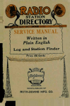
This chapter describes the hardware components of the Nearline Automated
Cartridge System (ACS) with the 9360 Library Storage Module (LSM). Figure 1-1
shows the 9360 LSM with an attached cartridge drive (CD) and the 9315
Electronics Module (EM). The following pages describe the hardware and
software components that make up the Nearline ACS and briefly explain how
each component functions.
Figure 1-1. 9360 LSM with Attached 9315 EM and Cartridge Drive
CD
PCAP
9315
EM
LCU
LMU
9871
CAPS
Tenth Edition
ACCESS
DOOR
C40032
1-1
Automated Cartridge System
■ Automated Cartridge System
The Nearline ACS is a fully automated, cartridge-based, tape-library system. The
operating system host software component or library server software sends a
cartridge move request to an LMU. The Library Management Unit (LMU) sends
the request to the Library Control Unit (LCU), which controls the electronics for
the LSM robot. The robot retrieves stored cartridges and mounts them onto CDs
or tape drives for read/write operations. When the read/write operations are
complete, the robot dismounts the cartridges and places them back into storage
cells in the LSM.
■ Nearline Software
The Nearline software is the interface between one or more client operating
systems and the hardware components of the ACS. The software acts as the
overall manager of the system and directs the automated mounting,
dismounting, and moving of cartridges in the LSM.
The software can reside in the client operating system or run on a server
platform with a portion of the package running in the client system. The
configuration depends on the type of operating environment in which the ACS
is running.
Refer to your software publications for more information about the Nearline
software.
■ Electronics Module and Library Management Unit
A 9312 or 9315 EM is attached to each 9360 LSM. The 9330 Library Management
Unit (LMU) is a stand-alone version and is not attached to the LSM.
9315 EM
Contains the LMU and the library control unit (LCU). Only one
9360 LSM in an ACS has a 9315 EM attached. This is because one
LMU can manage up to 16 LSMs in a maximum ACS
configuration.
9312 EM
Contains one LCU. In an ACS configuration with more than one
9360 LSM, the 9312 EM is attached to the 9360 LSMs that do not
have the 9315 EM attached.
In an ACS configuration that contains a 9330 stand-alone LMU,
the 9312 EM is attached to every 9360 LSM.
9330 LMU
Manages LSMs in an ACS configuration that includes a 9360
connected to 4410, 9310, or Extended Store LSMs.
The LMU manages the LSMs in an ACS. The LMU receives cartridge mount and
dismount requests from the client operating system by way of the Nearline
software.
1-2
Tenth Edition
9871
9360 Library Storage Module
The LMU sends instructions to the LCU attached to the LSM designated in the
move request. The LCU decodes the instructions into specific move commands,
and sends the commands to the LSM robot, where they are executed.
■ 9360 Library Storage Module
The LSM houses the cartridges and the robot. The 9360 LSM can be configured
for three different storage capacities–approximately 500, 750, or 1000 cartridges.
Storage capacity depends on the number of walls used to attach cartridge drives
or tape drives, pass-thru ports (PTPs), and cartridge access ports (CAPs)
installed.
Up to sixteen 9360 LSMs can be connected in a single ACS. If the cartridge
drives or tape drives are busy in one LSM, cartridges are automatically sent, by
way of a PTP, to the next LSM that has an available drive.
The access door on the 9360 LSM contains one or two CAPs and one priority
cartridge access port (PCAP).
Cartridge Access Port
The CAP is the storage area where you add cartridges to or remove cartridges
from an LSM without interrupting normal mounts and dismounts by the robot.
The CAP is on the LSM access door.
The standard CAP consists of two magazines, each containing 10 cartridge
storage cells. An optional CAP consists of three magazines, providing a total
capacity of 50 cartridges.
You can leave the magazines in the CAP and place single cartridges into the
magazine cells. You can also remove the magazines, load them with cartridges,
and place the magazines into the CAP.
In data processing environments where numerous enter and eject operations
are performed, you can maintain two sets of magazines. One set is in the CAP,
receiving cartridges in an eject operation; another set is outside the CAP,
preloaded with cartridges, ready to be placed in the CAP for an enter operation.
Priority Cartridge Access Port
The PCAP is the storage area where you add one cartridge to or remove one
cartridge from an LSM. A cartridge entered or ejected into the PCAP takes
priority over the movement of cartridges in the CAP. When the PCAP operation
is complete, the robot resumes its enter or eject operation through the CAP until
finished.
9871
Tenth Edition
1-3
9360 Library Storage Module
Pass-thru Port
When an ACS contains more than one LSM, the PTP connects a 9360 LSM to
another 9360 LSM, or to a 4410, 9310, or Extended Store LSM. When a request is
made to move a cartridge in one LSM to a drive or storage cell in another LSM,
the robot in the source LSM delivers the cartridge to the PTP. The PTP transfers
the cartridge to the receiving LSM. The robot in the receiving LSM removes the
cartridge from the PTP and delivers it to an available drive, storage cell, or to
another PTP.
The PTP can transfer one or two cartridges at a time.
The PTP is also used when the scratch tapes have been depleted in an LSM.
The PTP passes scratch tapes from an LSM with available tapes to an LSM that
has depleted its source of scratch tapes.
Figure 1-2 is a top view of two 9360 LSMs connected by a PTP. The figure
shows the location of the access door, CAPs, cartridge drives, and the 9315 and
9312 EMs, plus the arrangement of storage cells inside the LSM.
Figure 1-2. 9360 Library Storage Module, Top View
9315
EM
CARTRIDGE
STORAGE
CELLS
HAND
ASSEMBLY
9312
EM
CARTRIDGE
DRIVE
CARTRIDGE
ACCESS
PORTS
PASS-THRU
PORT
ROBOT
LSM
ACCESS
DOOR
1-4
C40033
Tenth Edition
9871
9360 Library Storage Module
Robot
The robot moves cartridges between the storage cells and the drives. The robot
consists of a theta assembly, Z mechanism, and hand assembly. Figure 1-3
shows these components.
Theta Assembly
The theta assembly consists of a vertical shaft that moves the hand assembly in
a circle. The theta assembly is supported at the center of rotation on a stationary
vertical pedestal, which is secured to the floor of the LSM.
Figure 1-3. 9360 LSM Robotic Components
Z MECHANISM
THETA
ASSEMBLY
HAND
ASSEMBLY
C40249
9871
Tenth Edition
1-5
9360 Library Storage Module
Z Mechanism
The Z mechanism is attached to the theta assembly. The Z mechanism moves
the hand assembly vertically along the cells and cartridge drives/tape drives in
the LSM.
Hand Assembly
The hand assembly grasps a cartridge and delivers it to the designated location,
such as a CAP or drive. The hand grasps the cartridge even if the LSM is
powered-off in an emergency, or if the system loses power. See “Removing a
Cartridge from the Hand Assembly” in Chapter 3, “Operating the 9360 LSM,” if
this occurs.
When the LSM is offline and not performing automated tape operations, you
can enter through the access door to perform manual tape operations. You
might need to move the robot to gain access to an attached tape drive, or to
remove a cartridge from its storage cell to perform a manual mount. See
“Moving the Robot” in Chapter 3, “Operating the 9360 LSM.”
LSM Safety Features
Safety features are incorporated into the 9360 LSM.
LSM Safety Interlocks
If the access door to the LSM is opened, electrical interlocks remove power
from the robot to prevent injury to anyone entering the LSM.
Prevention of LSM Access Door Closing
By following the safety procedures described in “Entering the LSM” in
Chapter 3, “Operating the 9360 LSM,” someone inside the LSM can prevent
anyone outside from closing the LSM access door.
LSM Emergency Power-off Switch
The LSM has two emergency power-off (EPO) switches, one on the inside of
the access door and one on the operator panel. Pressing either switch
immediately removes power from the EM and the LSM. See “Emergency PowerOff Switches” in Chapter 2, “Controls and Indicators,” for more information
about these switches. Figure 2-1 on page 2-2 shows the EPO switch on the LSM
operator panel. Figure 2-4 on page 2-15 shows the EPO switch inside the LSM.
LSM Smoke Detector
A smoke detector on the LSM top frame detects any smoke in the LSM. If smoke
is detected, an emergency power-off is performed on the LSM, removing power
from the robot and the LCU.
1-6
Tenth Edition
9871
Tape Drives
Internal Fire Suppression System Ports
The LSM contains two ports to which the user may connect a fire suppression
system. This system, as well as its controls and sensors, is supplied by a thirdparty vendor. A StorageTek marketing representative can provide more
information.
Robot Obstruction Search
During initialization, the robot moves slowly and sweeps through its full range
of motion. In this mode, current to the theta motor is limited, and you can stop
the robot with your hand. If any physical obstruction prevents the robot from
moving, the robot stops and an error is posted. If the robot movement is
disturbed but not completely stopped, the robot continues to sweep, but an
error is posted at the end of initialization and the robot does not go into normal
move mode.
■ Tape Drives
Tape drives can be attached to Panels 1 and 3 of the LSM.
Note: The 9360 supports a maximum of two drive types. For example, the LSM
may contain: (1) 9840 and TimberLine drives, (2) 9840 and SD-3 drives,
or (3) TimberLine and SD-3 drives.
The LSM cannot support 9840, SD-3, and Timberline drives.
The 9360 LSM works with the following tape drives:
•
4480 (18-track) Cartridge Subsystem
•
4490 (36-track) Cartridge Subsystem
•
9490 (36-track) Cartridge Subsystem [TimberLine]
•
9840 (288-track) Tape Drive
•
SD-3 (helical scan) Cartridge Subsystem [RedWood]
•
T9940 (288-track) Tape Drive
Notes:
1. The 9840 and T9940 drives require a 9741 Drive Cabinet.
2. 4480 or 4490 cartridge drives contain two or four tape transports.
3. 9490 cartridge drives contain two or four controller/transport units
(CTUs).
4. SD-3 cartridge drives contain from one to four CTUs.
9871
Tenth Edition
1-7
Tape Drives
Cartridge Subsystem
There are two designs for cartridge subsystems. One design covers the 4480
and 4490 product lines while a second design covers the 9490 and SD-3
product lines.
The 4480 or 4490 cartridge subsystem consists of one or two CDs within a
cabinet and one control unit (CU), each one in a separate cabinet. A CD can
have two or four transports, and it is cabled to the CU. The control unit is the
controller/interface between the CDs and the input/output (I/O) channels.
The 9490 or SD-3 cartridge subsystem consists of a cabinet containing
controller/transport units (CTUs). Each CTU has its own control unit that
interfaces with a single tape transport to perform read/write operations.
Refer to your cartridge subsystem publications for additional information.
9741 Drive Cabinet
The 9741 Drive Cabinet holds one to ten 9840 or T9940 Tape Drives. A 9741
can be attached to Panels 1 and 3 of the LSM.
Refer to your 9840 or T9940 Tape Drive publications for additional information.
1-8
Tenth Edition
9871
Controls and Indicators
2
This chapter shows the locations and describes the functions of the:
•
Library Storage Module (LSM) operator panel
•
Cartridge drive operator panel inside the LSM
•
Emergency power-off (EPO) switches
•
Power switch for the Library Management Unit (LMU)
Use the LSM operator panel to monitor and execute the various operations
associated with the LSM.
Use the transport/tape drive operator panel on the inside of the LSM to perform
manual cartridge mounts and dismounts when the LSM is offline.
Use the LSM and cartridge subsystem EPO switches, and the LMU power-off
switch, to immediately remove power from the units.
■ LSM Operator Panel
The LSM operator panel is beside the door of the LSM directly above the small
viewing window. The panel:
•
Shows status and diagnostic information
•
Shows number and location of cartridges in the Cartridge Access Ports
(CAPs) and the Priority Cartridge Access Port (PCAP)
•
Contains LSM switches: POWER, EPO, IPL, and RESET
•
Displays LMU status information when the LMU is in the EM
The lower area of the panel displays LMU information. For LSMs with the 9312
Electronics Module (EM) attached, this area remains blank.
Figure 2-1 on page 2-2 shows the panel, and Table 2-1 on page 2-3 lists and
describes each numbered item.
9871
Tenth Edition
2-1
LSM Operator Panel
Figure 2-1. LSM Operator Panel
StorageTek
1
FUNC: ONLN
CAP 1
Library Storage Module
ID:
L0:
L1:
PCAP
CAP 0
LSM
INFO
LIGHTS
LCD
CONFIG
4
2
5
ONLINE
3
OFFLINE
SERVICE REQ
MAINT
8
7
9
6
POWER
EMERGENCY POWER OFF
RESET
IPL
Library Management Unit
PROC ACTIVE
MASTER LMU
SERVICETEK
SERVICE REQ
13
10
12
11
C40035
2-2
Tenth Edition
9871
LSM Operator Panel
Table 2-1. LSM Operator Panel
Item1
Label
1
Type
Function
LCD Screen
Displays diagnostic and initialization messages.
Displays OFFLINE when initialization is
complete.
Displays status information about the LSM,
CAPs, and PCAP when the LSM is online. See
Figure 2-2 on page 2-5 and Table 2-2 on
page 2-6 for a complete description of this
display screen.
2
ONLINE
Indicator
Lights when the LSM is online.
3
OFFLINE
Indicator
Lights when the LSM is offline.
4
MAINT
Indicator
Lights in maintenance mode. Maintenance
mode is an LSM state in which diagnostic
routines can run. This mode is reserved for
service representatives and is not used for
operator tasks.
5
SERVICE REQ
Indicator
Lights when the LSM requires service. The LCD
indicates the problem error code. Contact
Customer Support Services.
6
POWER
Switch
Turns power on and off for the LSM and LCU.
When power is turned on, wake-up
procedures are started. When power is turned
off, an orderly shutdown of the LSM and the
LCU is performed, and power is removed.
7
EMERGENCY
POWER OFF
Momentary
Switch
Immediately removes all power from the LCU
and LSM and ends all activity in progress
within the LSM.
CAUTION:
Use this switch only in an emergency.
Note: If power is removed from the LSM
using the EPO switch, contact
Customer Support Services. Only a
service representative can restore
power to the unit.
9871
Tenth Edition
2-3
LSM Operator Panel
Table 2-1. LSM Operator Panel (Continued)
Item1
Label
Type
Function
8
RESET
Switch
Sends an interrupt message to the LCU
software.
This switch initiates an error dump of the
memory contents in the LCU.
Note: When the memory dump is complete,
you must IPL the LSM.
9
IPL
Switch/
Indicator
Switch: Resets LSM hardware and initiates an
IPL process.
Indicator: Lights when an IPL process is being
performed.
10
PROC ACTIVE2
Indicator
Lights if processor is functioning.
11
MASTER LMU2
Indicator
Lights when this LMU is the master LMU in a
dual LMU configuration. Blinks briefly when
this is the standby LMU in a dual LMU
configuration and polls the master LMU.
12
SERVICETEK2
Indicator
Lights when a problem has been detected in
the ACS and an alert message and error code
have been sent to the Remote Center or
operator console.
13
SERVICE REQ2
Indicator
Lights when the processor has detected an
error in the LMU. The LMU does not operate
under this condition.
Note: If this indicator is lit, contact Customer
Support Services.
Notes:
1. Numbers match the item numbers in Figure 2-1 on page 2-2.
2. This appears on the LSM operator panel of an LSM that is attached to a 9315 EM.
2-4
Tenth Edition
9871
LSM Operator Panel
Figure 2-2. LSM Operator Panel Status Screen
1
2
4
3
5
FUNC :
ONLN
ID: 02
L0:
L1:
7
ENTER
DOOR OPEN
LOCKED
LOCKED
5
CAP 1
00
PCAP
CAP 0
00
8
10
6
9
C40084
9871
Tenth Edition
2-5
LSM Operator Panel
Table 2-2. LSM Operator Panel Status Screen
Item
1
1
Category
Description
Status
FUNC : INIT
Indicates that the LSM is performing initialization routines.
These routines are performed when the LSM has been
powered-on, when the access door has been closed, or when
the IPL or the RESET switch has been pressed.
When the panel shows FUNC : INIT, the display area shows
diagnostic messages generated during initialization.
FUNC : OFFL
Indicates that the LSM is offline.
When the panel shows FUNC : OFFL, the display area shows
OFFLINE.
FUNC : ONLN
Indicates that the LSM is functioning and online.
When the panel shows FUNC : ONLN, the display area shows
status information about the CAPs and PCAP. Requests for you
to perform an action are also shown here.
2
Indicator
Identifies the LSM number in the ACS.
3
Indicator
Identifies the active LAN.
4
Indicator
Blinking heart indicates processor is active.
2-6
Tenth Edition
9871
LSM Operator Panel
Table 2-2. LSM Operator Panel Status Screen
Item
5
1
Category
Description
Status
Shows the status of the CAPs and prompts you to perform
enter or eject activities.
CAP 0 is the standard CAP. The CAP 1 display area is active
when the LSM uses the optional 30 cartridge CAP.
LOCKED
Lights when no CAP operations are in progress, or when the
CAP doors are closed after an enter or eject operation.
The following information is shown in the CAP status display
area during enter and eject operations:
Enter operations
Load Cartridges - ENTER
Lights when the CAP door is ready to be opened to place
cartridges in the CAP magazines.
Door Open
Lights when the CAP door is opened.
Eject operations
Remove Cartridges - EJECT
Lights when the CAP door is ready to be opened to remove
cartridges from the CAP magazines.
Door Open
Lights when the CAP door is opened.
Note: These panel displays appear when the CAP is operated
using commands entered at the operator console.
For more information about operating the CAP in
different modes and states, refer to your software
user’s guide.
9871
Tenth Edition
2-7
LSM Operator Panel
Table 2-2. LSM Operator Panel Status Screen
Item
6
1
Category
Description
Status
Shows the status of the PCAP and displays prompts for you to
perform enter or eject activities.
LOCKED
Lights when no PCAP operation is in progress or when the
PCAP door is closed after an enter or eject operation.
The following information is shown in the PCAP status display
area during enter and eject operations:
Enter operations
Load Cartridge - ENTER
Lights when the PCAP door is unlocked and ready to be
opened to receive a cartridge.
Door Open
Lights when the PCAP door is opened.
Eject operations
Remove Cartridge - EJECT
Lights when the PCAP door is ready to be opened to remove
cartridges.
Door Open
Lights when the PCAP door is opened.
2-8
Tenth Edition
9871
LSM Operator Panel
Table 2-2. LSM Operator Panel Status Screen
Item
7
1
Category
Description
Indicator
Rectangular boxes show the number and location of
magazines in the CAP. If the top magazines are not in CAP 0
or CAP 1, the boxes for those magazines are not shown. If the
bottom magazines are not in CAP 0 or CAP 1, the display does
not show any boxes, even if the top magazines are in place.
This is because the robot audits the CAP by starting at the
bottom of the CAP, and stops performing the audit when no
magazine is found.
Horizontal lines within the boxes show the number and
location of cartridges in each magazine.
During cartridge enter operations, this display increments after
cartridges have been entered into the CAP, the door is closed,
and the robot catalogs the CAP. It decrements as cartridges are
removed from the CAP.
During eject operations, this display increments as cartridges
are placed in the CAP for ejection.
Question marks in the boxes indicate the CAP door had been
opened and the status of cartridges in the CAP is unknown.
8
Indicator
The numbers next to CAP 1 and CAP 0 indicate the number of
cartridges in the CAPs.
During cartridge enter operations, this display field increments
after cartridges have been entered into the CAP, the door is
closed, and the robot catalogs the CAP. It decrements as the
cartridges are removed from the CAP.
During cartridge eject operations, this field increments as
cartridges are placed in the CAP for removal.
9
Indicator
The rectangular box next to PCAP shows a dash when a
cartridge is present in the PCAP. The box is blank when no
cartridge is present.
The field above the rectangular box displays the volume serial
number of the cartridge being entered or ejected through the
PCAP, if it has a readable label. If the cartridge is unlabeled, or
if the label cannot be read, CANT READ is displayed.
9871
Tenth Edition
2-9
Cartridge Drive Operator Panel
Table 2-2. LSM Operator Panel Status Screen
Item
1
10
Category
Description
Softkey
The second softkey from the left is not implemented.
CONTINUE
During initialization diagnostics, this switch clears a nonfatal
diagnostic failure condition and allows initialization to
continue.
LIGHTS
Toggles the two LSM ceiling lights on and off. The switch on
the TWS card must be in position 3 to activate this.
LSM INFO
Displays the level of microcode installed. Press DONE when
finished.
LCD CONFIG
Adjusts the intensity of the display panel. When this switch is
pressed, the StorageTek logo appears on the panel and
Adjust LCD Brightness appears above the logo.
Lighter, Darker, and DONE appear at the bottom of the
display with a switch for each option. Keep pressing the
lighter or darker switch to adjust the display to the desired
intensity. Press DONE when complete. The normal display
panel is restored.
Notes:
1. Numbers match the item numbers in Figure 2-2 on page 2-5.
■ Cartridge Drive Operator Panel
Different drive types use different techniques to display messages and provide
operator interaction. The following pages provide insight to the techniques.
4xxx Operator Panel
The 4xxx CD operator panel inside the LSM contains CD operator switch
assemblies and a CD message display. Indicators are enabled when the LSM is
offline, and disabled when the LSM is online. Refer to your software user’s
guide for a description of using a CD when the LSM is offline.
Figure 2-3 on page 2-11 shows switch and display locations.
Table 2-3 on page 2-12 describes each numbered item.
2-10
Tenth Edition
9871
Cartridge Drive Operator Panel
Figure 2-3. 4xxx CD Message Display and Operator Switch Assembly
6
0
1
SELECT
OPERATOR
OFFLINE
SELECT
OPERATOR
OFFLINE
5
1
2
3
4
R
E
W
I
N
D
U
N
L
O
A
D
7
R
E
A
D
Y
VIEW A
CD MESSAGE DISPLAY
CD
OPERATOR
SWITCH
ASSEMBLY
CD
MESSAGE
DISPLAY
DETAIL A
CD OPERATOR
SWITCH ASSEMBLY
CARTRIDGE
DRIVE
A
LIBRARY
STORAGE
MODULE
A
C40051
9871
Tenth Edition
2-11
Cartridge Drive Operator Panel
Table 2-3. 4xxx CD Message Display and Operator Switch Assembly
1
Label
Type
Function
1
SELECT
Green Light Bar
When lit, the transport is selected by the
control unit.
2
OPERATOR
Red Light Bar
Flashes on and off when you need to
perform an action.
3
OFFLINE
Yellow Light Bar
Lit when the transport OFFLINE switch is
pressed. This places the transport
physically offline.
10-character
alphanumeric
display
Displays transport messages. In a host
software component environment, it also
displays host messages.
Momentary
Switch
Verify that the READY LED is not lit. Then
press this momentary switch to rewind the
tape into a cartridge as far as the logical
BOT (beginning-of-tape). The READY
switch must be pressed and the LED must
light before another cartridge can be
loaded.
Item
4
5
REWIND
In an LSM that is offline, press this switch
and the UNLOAD switch at the same time,
for two seconds when the transport is
ready, to activate the transport message
display.
When the transport is ready, use the
REWIND and UNLOAD switches to adjust
the intensity of the message display. Press
both switches at the same time and the
display increases to the next level of
intensity every two seconds. The intensity
increments in intervals from off to 25%,
50%, and 100%. Release both switches
when you have the desired intensity.
6
UNLOAD
Momentary
Switch
Verify that the READY LED is not lit. Then
press this momentary switch to rewind a
tape completely into a cartridge, release
the leader block, and raise the transport
elevator so the cartridge can be removed.
The READY switch must be pressed and
the LED must light before another cartridge
can be loaded.
2-12
Tenth Edition
9871
Cartridge Drive Operator Panel
Table 2-3. 4xxx CD Message Display and Operator Switch Assembly (Continued)
Item
1
7
Label
Type
Function
READY
Momentary
Switch
Switch: Press this switch to set and reset
the ready enable switch.
Green LED
Indicator: Lit when the ready enable switch
is set.
When the ready state is set, the transport is
ready and the LED is lit. When the ready
state is not set and the LED is not lit, the
transport is prevented from becoming
ready.
Note: Make sure the READY indicator is lit
for each transport before leaving
the LSM and placing it online for
automated operations.
Notes:
1. Numbers match item numbers in Figure 2-3 on page 2-11.
9871
Tenth Edition
2-13
Cartridge Drive Operator Panel
9490 and SD-3 Operator Panel
9490 and SD-3 CTUs have a panel above the transport which integrates the
display, switches, and indicators into a single unit.
It has all of the switches and indicators of the 4xxx drives, but has two
additional indicators.
Indicator
Description
CLEAN
Indicates when the transport needs to be cleaned. A
cleaning cartridge should be loaded at the next
opportunity.
The indicator goes off when the cleaning cycle is
complete.
CRTG LOADED
Indicates a cartridge tape is loaded in the transport
9840 and T9940 Operator Panel
9840 and T9940 drives have an operator panel below the cartridge slot. This
panel contains the display, four indicators, and four switches.
Item
Description
activity
When on constantly, indicates tape is loaded and the drive is
ready. When flashing, tape is moving in the drive.
clean
Indicates when the drive needs to be cleaned. A cleaning
cartridge should be loaded at the next opportunity.
IPL
Pressing this switch causes an IPL and resets the drive.
Menu
Pressing this switch accesses the menu system, the menus,
and submenus.
power
When on constantly, indicates power on and IPL completed
successfully.
service
When on constantly, indicates a hardware error was
detected and the drive is not functional.
Select
Pressing this switch while in the Main Menu selects the
displayed choice or advances to a sub-menu.
Unload
Pressing this switch rewinds tape in the cartridge and ejects
the cartridge from the drive.
Refer to the 9840 Tape Drive User’s Reference Manual, 95739, or the T9940
Tape Drive Operator’s Guide, 95989, for additional information.
2-14
Tenth Edition
9871
Emergency Power-Off Switches
■ Emergency Power-Off Switches
Note: Use the EPO switch only in an emergency.
In an emergency, you can remove power immediately from the LSM and LCU,
the LMU, and the cartridge subsystem.
LSM EPO Switches
The LSM has two red EPO switches. One switch is on the inside of the access
door, as shown in Figure 2-4; the other switch is on the LSM operator panel, as
shown in Figure 2-5 on page 2-16. Both switches remove power from all
moving parts of the robot and the LCU.
Note: A person accidentally inside the LSM during power on can use the EPO
switch on the inside of the access door to immediately power off the
LSM.
See the instructions at “Emergency Powering off” on page 3-6.
Figure 2-4. LSM Internal EPO Switch
LSM
ACCESS
DOOR
LATCH
(INSIDE
LSM)
EPO
SWITCH
E40250
9871
Tenth Edition
2-15
Emergency Power-Off Switches
Figure 2-5. LSM Operator Panel EPO Switch
StorageTek
FUNC: ONLN
CAP 1
ONLINE
POWER
Library Storage Module
ID:
L0:
PCAP
OFFLINE
L1:
CAP 0
SERVICE REQ
MAINT
EMERGENCY POWER OFF
RESET
IPL
Library Management Unit
PROC ACTIVE
MASTER LMU
SERVICETEK
SERVICE REQ
C40356
2-16
Tenth Edition
9871
Emergency Power-Off Switches
LMU Power Switch
Note: Use the LMU power switch only in an emergency.
See Figure 2-6 for the location of the power switch.
Note: Some 9330 LMUs and 9315 EMs require a tool to open the front doors.
Contact Customer Support Services if the unit needs to be opened.
See the instructions at “Emergency Powering off” on page 3-3.
Figure 2-6. 9330 LMU Power Switch
LMU
SERVICE
PANEL
POWER
INDICATOR
LIGHT
POWER
SWITCH
(CB3)
STAND-ALONE
LMU
C40667
9871
Tenth Edition
2-17
Emergency Power-Off Switches
Cartridge Subsystem EPO Switch
Note: The 9840/T9940 drive does not have an EPO switch.
4xxx EPO Switch
Note: Use the EPO switch only in an emergency.
See Figure 2-7 for the location of the EPO switch on the control unit.
Pressing this switch immediately removes all power from the AC and DC power
supplies, and from the attached cartridge drives.
Note: This switch starts an uncontrolled power off and might cause a loss of
data.
See the instructions at “4480/4490 Cartridge Subsystem” on page 3-7.
Figure 2-7. Cartridge Subsystem EPO Switch
EPO
SWITCH
4480
C40357
2-18
Tenth Edition
9871
Emergency Power-Off Switches
9490 and SD-3 Unit Emergency Switch
Note: Use the Unit Emergency switch only in an emergency.
See Figure 2-8 for the location of the Unit Emergency switch on the rear of the
cartridge drive.
Pressing this switch immediately powers off the cartridge drive and all
controller transport units.
Note: This switch starts an uncontrolled power off and might cause a loss of
data.
See the instructions at “9490 and SD-3 Cartridge Drive” on page 3-8.
Figure 2-8. Cartridge Drive Power Control Panel
O
POWER
I
POWER
HOLD
INDICATOR
UNIT EMERGENCY
C40899
9871
Tenth Edition
2-19
Emergency Power-Off Switches
This page intentionally left blank.
2-20
Tenth Edition
9871
Operating the 9360 LSM
3
This chapter contains the procedures for:
•
“Displaying LMU and LSM Status”
•
“Powering on and Powering off the LMU”
•
“Powering on and Powering off the LSM” on page 3-4
•
“Powering off the Cartridge Subsystem” on page 3-7
•
“Operating in Automated Mode” on page 3-9
•
“Operating in Manual Mode” on page 3-17
■ Displaying LMU and LSM Status
Refer to your software user’s guide and enter the command at the operator
console to display:
•
Current status of the Library Storage Modules (LSMs)
•
Current status of the Library Management Unit (LMU)
•
Online, offline, or standby status of each LMU station or port
■ Powering on and Powering off the LMU
The following pages describe how to power on and power off the LMU in those
units that allow customer access.
Note: Some 9330 LMUs and 9315 Electronic Modules (EMs) require a tool to
open the front doors. The panels and switches in these units are never
accessible to operators. Electrical components in the units can cause
serious injury. Contact Customer Support Services if the unit needs to be
opened.
If the front door of your unit does not require a tool to open, you may perform
these procedures:
•
•
•
9871
“Powering on” on page 3-2
“Powering off” on page 3-2
“Emergency Powering off” on page 3-3
Tenth Edition
3-1
Powering on and Powering off the
Powering on
To power on the LMU:
1. Open the front door of the 9330 LMU or 9315 EM.
2. Press the power switch on the LMU, as shown in Figure 3-1 on page 3-3.
•
The power indicator on the front of the LMU turns on.
•
The LMU performs a series of diagnostic routines and the service panel
displays selftest and booting information.
•
The HARD DISK ACTIVE indicator turns on.
•
The PROCESSOR ACTIVE indicator turns on.
3. Refer to your software user’s guide and make sure that the ACS is ready to
bring online.
Note: If the LMU does not power on, contact Customer Support Services and
report the problem.
Powering off
CAUTION:
LOSS OF TAPE MOUNT REQUESTS. MAKE SURE LSMs AND ACS ARE
OFFLINE BEFORE POWERING OFF THE LMU.
To power off the LMU:
1. Refer to your software user’s guide and place the LSMs offline.
2. Stop all tape activity and place the ACS offline.
3. Open the front door of the 9330 LMU or 9315 EM.
4. Press the power switch on the LMU.
3-2
Tenth Edition
9871
Powering on and Powering off the
Emergency Powering off
Note: Use the following procedure only in an emergency.
To power off the LMU in an emergency:
1. Open the front door of the 9330 LMU or 9315 EM.
2. Press the power switch on the LMU as shown in Figure 3-1.
3. Notify Customer Support Services to dispatch a service representative to
restore power to the LSM as described in Chapter 4, “Obtaining Support.”
Figure 3-1. LMU Power Switch
+267
&6( &65&
/0%
/0%
/0%
/0%
/0$
/03
CB3
POWER
SWITCH
C40900
9871
Tenth Edition
3-3
Powering on and Powering off the LSM
■ Powering on and Powering off the LSM
The following pages describe how to power on and power off the LSM. The
pages also provide IPL and emergency power off procedures.
Powering on
When power is applied to the LSM, the functional microcode on the LMU hard
drive is downloaded from the LMU to the LCU. The microcode controls the
robot. The LSM will not operate without this code.
Note: The LMU must be powered on for the code to be downloaded to the
LCU.
To power on the LSM:
1. Press the POWER switch on the LSM operator panel. See Figure 3-2 on
page 3-5.
•
The panel displays PROM and boot diagnostic routines.
•
The panel displays OFFLINE when the diagnostic and initialization
routines are complete.
Note: If the LSM does not power on, contact Customer Support Services and
report the problem.
2. Refer to your software user’s guide and place the LSM online to perform
automated operations.
Powering off
To power off an LSM:
1. Refer to your software user’s guide and place the LSM offline.
The panel displays OFFLINE.
2. Press the POWER switch on the LSM operator panel. See Figure 3-2 on
page 3-5.
IPLing
When an IPL is performed on the LSM, the microcode is downloaded from the
LMU to the LCU, and the LSM performs a full initialization routine.
To IPL an LSM:
1. Refer to your software user’s guide and place the LSM offline.
2. Press the IPL switch on the LSM operator panel. See Figure 3-2 on page 3-5.
3-4
Tenth Edition
9871
Powering on and Powering off the LSM
•
The panel displays PROM and boot diagnostic routines.
•
The panel displays Loading functional code.
•
The LSM performs an initialization routine.
•
The panel displays OFFLINE when the IPL is complete.
Figure 3-2. LSM Operator Panel Switches
StorageTek
FUNC: ONLN
CAP 1
ONLINE
POWER
Library Storage Module
ID:
L0:
PCAP
OFFLINE
L1:
CAP 0
SERVICE REQ
MAINT
EMERGENCY POWER OFF
RESET
IPL
Library Management Unit
PROC ACTIVE
MASTER LMU
SERVICETEK
SERVICE REQ
C40356
9871
Tenth Edition
3-5
Powering on and Powering off the LSM
3. Refer to your software user’s guide and place the LSM online to perform
automated operations.
When the LSM IPL is complete, the LSM establishes communication with the
LMU. The LSM must be placed online to perform automated operations.
Emergency Powering off
Note: Use the following procedure only in an emergency.
To power off an LSM in an emergency:
1. Press the EMERGENCY POWER OFF switch on the LSM operator panel
(Figure 3-2 on page 3-5), or the EPO switch on the inside of the LSM access
door (Figure 3-3).
Note: This action immediately removes all power from the robot and the
LCU.
2. Notify Customer Support Services to dispatch a service representative to
restore power to the LSM as described in Chapter 4, “Obtaining Support.”
Figure 3-3. LSM Internal EPO Switch
LSM
ACCESS
DOOR
LATCH
(INSIDE
LSM)
EPO
SWITCH
E40250
3-6
Tenth Edition
9871
Powering off the Cartridge Subsystem
■ Powering off the Cartridge Subsystem
Note: The 9840/T9940 drive power switch is not accessible because the drive
in located inside a locked cabinet.
4480/4490 Cartridge Subsystem
CAUTION:
LOSS OF DATA. Pressing the EPO switch starts an uncontrolled power
off and might cause a loss of data. USE THE EPO SWITCH ONLY IN AN
EMERGENCY.
To power off a cartridge subsystem in an emergency:
1. Press the EPO switch on the control unit, as shown in Figure 3-4.
2. Notify Customer Support Services to dispatch a service representative to
restore power to the subsystem as described in Chapter 4, “Obtaining
Support.”
Figure 3-4. Cartridge Subsystem EPO Switch
EPO
SWITCH
4480
C40357
9871
Tenth Edition
3-7
Powering off the Cartridge Subsystem
9490 and SD-3 Cartridge Drive
CAUTION:
LOSS OF DATA. Pressing the Unit Emergency switch starts an
uncontrolled power off and might cause a loss of data. USE THE UNIT
EMERGENCY SWITCH ONLY IN AN EMERGENCY.
To power off a cartridge drive in an emergency:
1. Locate the Unit Emergency switch on the power control panel at the rear of
the cartridge drive.
2. Lift the plastic cover to allow access to the switch.
3. Press the red Unit Emergency switch, shown in Figure 3-5.
4. Notify Customer Support Services to dispatch a service representative to
restore power to the subsystem as described in Chapter 4, “Obtaining
Support.”
Figure 3-5. Unit Emergency Switch
O
POWER
I
POWER
HOLD
INDICATOR
UNIT EMERGENCY
C40899
3-8
Tenth Edition
9871
Operating in Automated Mode
■ Operating in Automated Mode
When the LSM is online and the robot is mounting and dismounting cartridges,
you should monitor console messages and respond appropriately to make sure
that the library continues to operate efficiently.
You might find the following list of procedures helpful:
•
“Entering Cartridges through the CAP” on page 3-10
•
“Ejecting Cartridges through the CAP” on page 3-13
•
“Entering Cartridges through the PCAP” on page 3-14
•
“Ejecting Cartridges through the PCAP” on page 3-16
Note: The operation steps and panel displays listed in the following pages
describe how the CAP and PCAP operate when enter and eject
commands are issued at the operator's console.
Refer to your software user’s guide for the command syntax for the
enter and eject commands and for more information about operating
the CAP and PCAP in different modes and states.
9871
Tenth Edition
3-9
Operating in Automated Mode
Entering Cartridges through the CAP
To enter cartridges through the CAP:
1. Issue the enter command at the operator console.
•
The CAP status display area on the LSM operator panel displays ENTER.
•
The CAP door unlocks.
2. Open the CAP door by pulling the CAP latch as shown in Figure 3-6.
•
The panel displays Door Open, indicating that the CAP is open.
Figure 3-6. Opening the Cartridge Access Port
PCAP
A
CAP
LATCH
DETAIL A
CAP 1
(OPTIONAL)
3-10
CAP 0
LSM
ACCESS
DOOR
Tenth Edition
C40039
9871
Operating in Automated Mode
3. Remove the CAP magazines from the LSM door. Lift the magazines up
approximately 25.4 mm. (1 in.) and pull them out, as shown in Figure 3-7.
Note: You can also add cartridges directly to the magazine cells without
removing the magazines from the CAP.
4. Place a cartridge into a magazine cell as shown in Figure 3-8 on page 3-12.
Note: Insert cartridges so they lie flat, with the customer label on top and
the volume serial number (VOLSER) facing you as shown in
Figure 3-8 on page 3-12.
5. Continue until all the cartridges have been placed in the magazines, or until
the magazines are full.
6. Place the magazines back into the CAP.
Note: Make sure that a magazine is always placed into the bottom
magazine area. You do not need to replace the top magazines unless
you need them.
If only the bottom magazine is replaced, the status display for the
CAP on the LSM operator panel shows only the bottom magazine is
present. If only the top magazines are replaced in either the
standard or optional CAP, the status display for the CAPs shows that
no magazines are present, and the robot does not attempt to retrieve
a cartridge from the CAP.
Figure 3-7. Removing Cartridge Access Port Magazines
E40251
9871
Tenth Edition
3-11
Operating in Automated Mode
Figure 3-8. Placing Cartridges into Magazine Cells
CUSTOMER
LABEL
VOLSER
LABEL
E40252
7. Close the CAP door.
•
The panel displays LOCKED when the CAP door is closed and locked
properly.
•
The rectangular boxes on the panel show horizontal dashes as the robot
catalogs the CAP. The dashes indicate the number and location of
cartridges in the CAP magazines. The two-digit display field next to the
boxes also shows the number of cartridges placed in the CAP.
•
The robot stores all cartridges with readable labels.
•
The number of dashes in the rectangular boxes and the two-digit value
on the panel are reduced as the cartridges are removed from the CAP.
Note: The robot’s ability to move cartridges with unreadable labels or to move
cartridges placed in the CAP incorrectly, depends on the way the
Nearline software is configured.
Under normal conditions, when a cartridge is placed in the CAP
incorrectly or with an unreadable label, the robot audits the CAP,
displays a dash in the rectangular box in the CAP status display area on
the LSM operator panel, recognizes that a cartridge is present in the
CAP, but does not move it.
You must remove the cartridge from the CAP.
3-12
Tenth Edition
9871
Operating in Automated Mode
8. Refer to your software user’s guide and restore the CAP to the locked
position.
Ejecting Cartridges through the CAP
To eject cartridges through the CAP:
1. Issue the eject command at the operator console.
•
The CAP status display area on the LSM operator panel displays EJECT.
•
The robot places cartridges into the CAP until all specified cartridges are
in the CAP or all CAP cells are filled.
•
The rectangular boxes on the panel show a dash as each cartridge is
placed in the CAP. The dashes show the number and location of
cartridges in the CAP magazines. The two-digit display field next to the
boxes also shows the number of cartridges placed in the CAP.
2. Open the CAP door.
•
The panel displays Door Open.
3. Remove all loaded magazines from the CAP and take the cartridges out of
the magazines.
Notes:
1. You can also remove individual cartridges from the magazines.
2. Do not leave cartridges in the CAP or the panel will display Remove
Cartridges.
4. Place the magazines back into the CAP.
Note: Make sure that the bottom magazine is placed in the CAP.
5. Close the CAP door.
•
The panel displays LOCKED when the CAP door is closed and locked
properly.
The robot continues filling the CAP until all the required cartridges have been
ejected. When the panel displays Remove Cartridges EJECT, repeat steps
2 through 5.
9871
Tenth Edition
3-13
Operating in Automated Mode
Entering Cartridges through the PCAP
To enter cartridges through the PCAP:
1. Issue the enter command at the operator console.
•
The PCAP status display area on the LSM operator panel displays
ENTER.
2. Open the PCAP door as shown in Figure 3-9.
•
The panel displays Door Open.
Figure 3-9. Priority Cartridge Access Port, Closed
PCAP
PCAP
LATCH
A
DETAIL A
CAP 1
(OPTIONAL)
3-14
CAP 0
LSM
ACCESS
DOOR
Tenth Edition
C40040
9871
Operating in Automated Mode
3. Place the cartridge into the PCAP as shown in Figure 3-10.
Note: Insert the cartridge so that it lies flat, with the customer label on top
and the VOLSER facing you.
4. Close the PCAP door.
•
The panel displays LOCKED.
•
The panel displays ??????, indicating that the VOLSER is unknown.
•
As the robot audits the PCAP, the panel displays the VOLSER of the
cartridge entered and shows a dash in the rectangular box, indicating
that a cartridge is present in the PCAP.
Note: The robot does not move a cartridge with an unreadable label or a
cartridge placed in the PCAP incorrectly. When this occurs, the panel
displays CANT READ and you must remove the cartridge.
5. Refer to your software user’s guide and restore the PCAP to the locked
position.
Figure 3-10. Placing the Cartridge into the PCAP
CUSTOMER
LABEL
VOLSER
LABEL
TAPE
INSERTION
DIRECTIONS
PCAP
9871
E40041
Tenth Edition
3-15
Operating in Automated Mode
Ejecting Cartridges through the PCAP
To eject a cartridge through the PCAP:
1. Issue the eject command at the operator console.
•
The robot places the cartridge into the PCAP.
•
The robot audits the PCAP.
•
The PCAP status display area on the LSM operator panel displays the
VOLSER of the cartridge.
•
A dash in the rectangular box appears in the display area and indicates
that a cartridge is present.
•
The panel displays CANT READ if the cartridge is unlabeled or if the
label is unreadable.
2. Open the PCAP door as shown in Figure 3-9 on page 3-14.
•
The panel displays EJECT.
3. Remove the cartridge from the PCAP.
4. Close the PCAP door.
3-16
•
The panel displays LOCKED.
•
The VOLSER is replaced by ?????? on the panel.
•
The robot audits the PCAP and replaces the question marks with a
blank field, indicating that the status is known and that no cartridge is
present.
Tenth Edition
9871
Operating in Manual Mode
■ Operating in Manual Mode
The following pages contain operations you can perform when the LSM is in
manual mode.
Before starting any of these operations, you must take precautions against
electrostatic discharge (ESD).
Note: Even a small electrostatic discharge could damage an electrical
component inside the library. A damaged component might not fail
immediately, but over time, it will become worse, possibly causing an
intermittent problem.
Entering the LSM
To safely enter the LSM:
1. Place the LSM offline.
The LSM operator panel displays OFFLINE when the LSM is offline and not
performing automated operations.
CAUTION:
LOSS OF MOUNT REQUESTS. If you open the lock access door (LAD)
when the LSM is online, a switch is activated which automatically
causes a software interrupt and stops the robot. MAKE SURE THE LSM
IS OFFLINE BEFORE OPENING THE LAD.
2. Open the LAD as shown in Figure 3-11 on page 3-18 and Figure 3-12 on
page 3-19.
The LSM operator panel displays DO NOT ENTER.
3. Insert the key and unlock the latch.
4. Pull the paddle handle to release the door latches and open the access
door.
5. Turn the key to the locked position, remove the key, and shut the LAD.
This action locks the access door in the open position.
•
•
9871
The panel displays SAFE TO ENTER.
The lights turn on inside the LSM.
Tenth Edition
3-17
Operating in Manual Mode
Figure 3-11. LSM Access Door, Outside View
PCAP
LSM
OPERATOR
PANEL
SMALL
VIEWING
WINDOW
LSM
ACCESS
DOOR
LATCH
LAD
SWITCH
KEY
LOCK
CAP 1
(OPTIONAL)
CAP 0
LSM
ACCESS
DOOR
DOOR
LOCK
COVER
(SHOWN
OPEN)
C40044
3-18
Tenth Edition
9871
Operating in Manual Mode
Figure 3-12. LSM Access Door Latch and Door Lock Cover
LSM
ACCESS
DOOR
LATCH
LAD
SWITCH
KEY
LOCK
DOOR
LOCK
COVER
!
DOOR
LOCK
COVER
(SHOWN
OPEN)
WARNING
LABEL
C40045
6. Enter the LSM with the LAD key.
Taking the key inside the LSM prevents another person from closing and
locking the access door after you enter.
After you have opened an LSM door:
CAUTION:
COMPONENTS ARE SENSITIVE TO STATIC ELECTRICITY. MAKE SURE
YOU TOUCH UNPAINTED METAL BEFORE REACHING INSIDE THE
LIBRARY.
7. Touch an unpainted metal surface with your finger, such as the LSM frame
just inside the access door.
8. Keep your body movement to a minimum as you touch the drives or LSM
components.
Note: Antistatic wrist straps with clip-on ends are commercially available.
9871
Tenth Edition
3-19
Operating in Manual Mode
Moving the Robot
When you have opened the LSM access door, you might need to move the
robot to make it easier to gain access to the stored cartridges or to the attached
cartridge drives.
Read and observe the following caution and warning notices before attempting
to move any portion of the robot.
CAUTION:
ROBOT COMPONENT DAMAGE.
•
Body oils can corrode shiny polished surfaces or lubricated parts.
DO NOT TOUCH POLISHED SURFACES OR LUBRICATED PARTS.
•
ONLY MOVE HAND AND THETA ASSEMBLY AS SHOWN (SEE
Figure 3-13 on page 3-21 THROUGH Figure 3-15 on page 3-23).
•
DO NOT FORCE HAND AND THETA ASSEMBLIES.
If the hand or theta assemblies do not move freely, contact Customer
Support Services.
•
If the LSM goes offline due to an EPO or power failure, the reach
mechanism might be extended into a storage cell or transport. If the
robot is moved vertically or horizontally when this condition exists,
the hand assembly will be seriously damaged. MAKE SURE THE
REACH MECHANISM IS FULLY RETRACTED TO HOME POSITION
BEFORE MOVING ANY ROBOT PART.
WARNING:
BODILY INJURY.
3-20
•
KEEP HANDS OFF EXPOSED ELECTRICAL PARTS WHEN MOVING
ANY PART OF ROBOT.
•
DO NOT MOVE HAND ASSEMBLY BY GRASPING THE COUNTERWEIGHT ASSEMBLY. The moving components have pinch-points
that can injure fingers or hands.
•
DO NOT PLACE HAND/FINGERS ON COUNTERWEIGHT ASSEMBLY
TRACKS WHEN MOVING ASSEMBLY. A severe pinch-point exists
between the counterweight assembly and the tracks it moves on that
can injure fingers or hands.
Tenth Edition
9871
Operating in Manual Mode
Raising and Lowering the Hand Assembly
CAUTION:
LSM PREVENTED FROM INITIALIZING. If you push the hand up too fast,
the carriage belt slackens and can catch on the counterweight, which
will prevent the LSM from initializing. MOVE THE HAND ASSEMBLY
SLOWLY AND CAREFULLY.
If you need to move the hand assembly vertically, slowly and carefully pull
down or push up by grasping the brace beneath the hand, as shown in
Figure 3-13.
Note: If the LSM does not initialize, notify Customer Support Services.
Figure 3-13. Moving the Hand Assembly Vertically
HAND
ASSEMBLY
C40046
9871
Tenth Edition
3-21
Operating in Manual Mode
Rotating the Theta Assembly
CAUTION:
EQUIPMENT DAMAGE. Theta assembly does not move a full 360
degrees. DO NOT FORCE THETA ASSEMBLY IF YOU MEET RESISTANCE
WHILE TURNING IT.
If you need to rotate the theta assembly, grasp it and carefully turn the
assembly, as shown in Figure 3-14.
Note: If the assembly meets resistance and stops before the desired position is
reached, it has contacted a stopping mechanism (Figure 3-15 on
page 3-23).
Rotate the shaft in the opposite direction.
Figure 3-14. Rotating the Theta Assembly
Z MECHANISM
THETA
ASSEMBLY
E40047
3-22
Tenth Edition
9871
Operating in Manual Mode
Figure 3-15. Limits for Rotating the Theta Assembly
FIRST CD
OR
DRIVE
CABINET
ROBOT
CARTRIDGE
ACCESS
PORTS
STOP
HERE
OPTIONAL CD
OR
DRIVE
CABINET
LSM
ACCESS
DOOR
C40049
Locating a Cartridge in the Storage Cells
Figure 3-16 on page 3-24 through Figure 3-18 on page 3-26 show the locations
of the panels, rows, and columns of the cartridge storage cells in the 9360 LSM.
Refer to these figures to locate a cartridge in the LSM. The figures also show the
locations of reserved storage cells used for diagnostic and cleaning cartridges.
Note: The figures show the types of panels and storage cell locations in some
typical configurations. Additional panel types, with variations in the
placement of the storage cells, are not shown.
CAUTION:
LSM PREVENTED FROM GOING ONLINE. The LSM will not be able to
complete its initialization routines and can not be placed online if
cartridges are present in reserved cells. DO NOT PLACE CARTRIDGES
IN RESERVED CELLS.
9871
Tenth Edition
3-23
Operating in Manual Mode
Figure 3-16. Cartridge Locations, Top View
DRIVE 0
FIRST
CARTRIDGE
DRIVE
OR
DRIVE
CABINET
COLUMN 1
PANEL 1
PASSTHRU
PORT
COLUMN 0
PANEL 2
PASSTHRU
PORT
PA NE L 1
P
2
PA N
EL
EL
AN
0
3
COLUMN 0
PANEL 3
NE
P
AN
EL
L
COLUMN 0
PANEL 0
4
PA
CAP 1
OPTIONAL
CARTRIDGE
DRIVE
OR
DRIVE
CABINET
CAP 0
LSM
ACCESS
DOOR
COLUMN 0
PANEL 4
DRIVE 1
3-24
Tenth Edition
C40052
9871
PANEL 1
PANEL 2
PANEL 3
PANEL 4
ACCESS DOOR
R
O
W
S
0
COLUMNS
0
1
2
3
COLUMNS
0
1
4
5
COLUMNS
0
1
2
3
COLUMNS
4
5
0
1
2
3
COLUMNS
4
5
0
1
2
3
4
5
R
O
W
S
0
TRANSPORT 0
PCAP
TRANSPORT 1
10
10
CAP 0
0
TRANSPORT 2
Tenth Edition
20
20
TRANSPORT 3
1
30
30
DRIVE 0
MASTER
CALIB.
AREA
41
0
1
2
3
4
5
0
41
1
0
1
2
3
4
5
0
1
2
3
4
5
0
1
2
3
4
5
4 CELLS
250 CELLS
252 CELLS
193 CELLS
DIAGNOSTIC CARTRIDGE - RESERVED
IN-TRANSIT CELL - RESERVED
CLEANING CARTRIDGE - RESERVED
STANDARD WALL CONFIGURATION
C40053
3-25
Operating in Manual Mode
CAP 0 : 2 MAGAZINES
(10 CELLS EACH)
250 CELLS
Figure 3-17. Cartridge Locations With Cartridge Drives
9871
PANEL 0
PANEL 2
PANEL 3
PANEL 4
ACCESS DOOR
R
O
W
S
0
COLUMNS
1
0
2
3
COLUMNS
1
0
4
5
10
Tenth Edition
20
30
0
1
0
1
2
3
1
2
3
4
5
4
5
0
1
2
COLUMNS
4
5
T
DRIVE 10
0
1
2
T
DRIVE 11
T
DRIVE 2
T
DRIVE 12
T
DRIVE 3
T
DRIVE 13
T
DRIVE 4
T
DRIVE 14
CAP 0
T
DRIVE 5
T
DRIVE 15
0
T
DRIVE 6
T
DRIVE 16
T
DRIVE 7
T
DRIVE 17
T
DRIVE 8
T
DRIVE 18
T
DRIVE 9
T
DRIVE 19
0
3
4
5
R
O
W
S
0
CAP 1
T
DRIVE 1
0
PCAP
10
1
20
1
2
2
3
30
0
1
MASTER
CALIB.
AREA
41
0
T
DRIVE 0
COLUMNS
3
COLUMNS
41
1
0
1
2
3
4
5
0
1
2
3
4
5
0
1
4
5
CAP 0 : 2 MAGAZINES
CAP 1 : 3 MAGAZINES
(10 CELLS EACH)
242 CELLS
4 CELLS
242 CELLS
144 CELLS
109 CELLS
DIAGNOSTIC CARTRIDGE - RESERVED
IN-TRANSIT CELL
(NO CARTRIDGE)
STK
CLEANING
CARTRIDGE
DIAGNOSTIC OPEN
IN-TRANSIT CELL - RESERVED
CLEANING CARTRIDGE - RESERVED
OPTIONAL WALL CONFIGURATION WITH 10-DRIVE CABINETS
C40876
Operating in Manual Mode
PANEL 1
Figure 3-18. Cartridge Locations with 10-Drive Cabinets
3-26
PANEL 0
9871
Operating in Manual Mode
Removing a Cartridge from the Hand Assembly
If the LSM goes offline due to a power failure, or the EPO switch has been
pushed when the robot is moving a cartridge, the cartridge might be left in the
hand assembly. You can remove it from the hand and manually mount it into a
drive/transport for a read/write operation or into the CAP.
Refer to your software user’s guide for a complete description of operating the
LSM when it is offline.
Before starting this operation, you must take precautions against ESD.
Note: Even a small electrostatic discharge could damage an electrical
component inside the library. A damaged component might not fail
immediately, but over time, it will become worse, possibly causing an
intermittent problem.
Refer to Figure 3-19 on page 3-28 and Figure 3-20 on page 3-28. To remove a
cartridge from the hand assembly:
Note: Do not enter the LSM until you are familiar with the procedure described
in “Entering the LSM” on page 3-17.
CAUTION:
ROBOT DAMAGE. FOLLOW PROCEDURES IN “Moving the Robot” on
page 3-20 TO PREVENT DAMAGE.
1. Rotate the theta assembly until the hand assembly is facing the LSM access
door.
2. Refer to Figure 3-19 on page 3-28 and rotate the pulley for the reach
mechanism until the gripper mechanism is extended to its full position, as
shown in Figure 3-20 on page 3-28.
3. Hold the reach mechanism pulley with one hand and grasp the cartridge
with the other.
4. Pull gently on the cartridge until it is released from the gripper mechanism,
as shown in Figure 3-20 on page 3-28.
CAUTION:
EQUIPMENT DAMAGE. If the gripper mechanism is left extended and the
robot is turned manually, the gripper will strike a storage cell. If it is left
extended and the hand assembly is facing the LSM access door when it
is closed, the door will strike the gripper mechanism. MAKE SURE
GRIPPER MECHANISM IS IN HOME POSITION.
5. Turn the belt drive for the reach mechanism until the gripper mechanism is
back in its home position.
9871
Tenth Edition
3-27
Operating in Manual Mode
Figure 3-19. Extending the Gripper Assembly
REACH
MECHANISM
BELT
DRIVE
TAPE
CARTRIDGE
(SHOWN
RETRACTED)
C40061
Figure 3-20. Removing a Cartridge from the Hand Assembly
REACH
MECHANISM
(SHOWN
EXTENDED)
GRIPPER
MECHANISM
REACH
MECHANISM
BELT
DRIVE
TAPE
CARTRIDGE
C40256
3-28
Tenth Edition
9871
Operating in Manual Mode
Performing Manual Mounts–Host Software Component
The following pages describe how to perform manual mounts in an LSM that is
offline. These procedures apply only to an ACS that is running under the host
software component (HSC) version of the Nearline software.
If your ACS is running under a non-host software component version, contact
your systems administrator for manual mount information.
Resetting the Transport Display
Note: Only the 4480/4490 drives require resetting of the transport display.
At the beginning of manual mode operation, each 4480/4490 transport is in a
HOLD OFF LOAD condition. In this condition, the message display panel above
the transport is blank and the transport does not load if a cartridge is mounted.
This condition must be cleared before you mount cartridges manually.
Figure 3-21 on page 3-30 shows the locations of the 4480/4490 switches and
message display panel. To reactivate the transport display and clear the HOLD
OFF LOAD condition:
Note: Do not enter the LSM until you are familiar with the procedure described
in “Entering the LSM” on page 3-17.
1. If the transport contains an unloaded cartridge, remove it from the transport
and the LSM.
Do not place it in an empty storage cell in the LSM. It must be entered
through the CAP for the LSM to properly catalog it.
2. With the transport empty and the READY indicator on, hold down the
REWIND and UNLOAD switches simultaneously for about 4 seconds.
WARNING:
BODILY INJURY. Empty transports perform elevator motions if the
control unit is powered off and then powered on. KEEP FINGERS AWAY
FROM TRANSPORT OPENINGS UNTIL TRANSPORT DISPLAY IS
ACTIVATED.
3. If the READY indicator is off:
•
Press the READY switch.
•
Hold down the REWIND and UNLOAD switches at the same time.
The transport display must be activated and the HOLD OFF LOAD
condition cleared for each nonbusy transport that does not have an active
display.
Note: Allocated transports display the cartridge volume serial number and
the cell location. An asterisk is displayed if the transport is not
allocated to a mount request.
9871
Tenth Edition
3-29
Operating in Manual Mode
Figure 3-21. Cartridge Drive, Inside View
0
1
SELECT
OPERATOR
OFFLINE
SELECT
OPERATOR
OFFLINE
R
E
W
I
N
D
U
N
L
O
A
D
R
E
A
D
Y
VIEW A
CD MESSAGE DISPLAY
DETAIL A
CD OPERATOR
SWITCH ASSEMBLY
CD
OPERATOR
SWITCH
ASSEMBLY
CD
MESSAGE
DISPLAY
0
0
CARTRIDGE
DRIVE
1
1
A
LIBRARY
STORAGE
MODULE
A
C40668
3-30
Tenth Edition
9871
Operating in Manual Mode
When an unallocated transport is properly reset, this display appears:
*
Setting Transport Display Intensity
Note: Only the 4480/4490 drives allow setting of the transport display
intensity.
To adjust the intensity of the transport display:
1. Press the REWIND and UNLOAD switches at the same time.
Note: When the switches are held down, the display dims to the next level
of intensity (100 percent, 50 percent, 25 percent, and off) every 2
seconds.
2. Release the switches when a suitable intensity is present.
Locating a Cartridge in the LSM
The following pages describe how to locate a cartridge in the LSM. The
cartridge VOLSER and cell location are provided in a console message and on
the transport/drive display panel.
Cartridge Location in the Console Message
The console message provides the VOLSER and cell location of the cartridge,
and the address of the transport/drive allocated for the mount. Before entering
the LSM, write down the VOLSER, cell location, and transport/drive address.
Cartridge Location on the Message Display Panel
Inside a manual mode LSM, the transport/drive display panel–when the
transport is allocated by the operating system for a mount–toggles between the
VOLSER and cell location of the requested cartridge. The VOLSER appears as
seven characters: the six-character volume serial number prefixed with an M,
indicating the transport is waiting for the mount.
The cell location appears in the following format:
l
l
p
p
r
r
c
c
where:
9871
ll
identifies an LSM
pp
identifies an LSM panel
rr
identifies a row in the panel
cc
identifies a column in the row
Tenth Edition
3-31
Operating in Manual Mode
An example of the location displayed is:
0
1
0
2
1
1
0
4
In the example, the cartridge is in LSM 01, Panel 02, Row 11, Column 4.
Manually Mounting a Cartridge
Before starting any of these operations, you must take precautions against ESD.
Note: Even a small electrostatic discharge could damage an electrical
component inside the library. A damaged component might not fail
immediately, but over time, it will become worse, possibly causing an
intermittent problem.
When the operating system sends a mount request for a volume residing in a
manual mode LSM, the transport/drive display shows the location of the
cartridge.
Note: Do not enter the LSM until you are familiar with the procedure described
in “Entering the LSM” on page 3-17.
To mount the cartridge into a transport:
1. Activate the transport display. See “Resetting the Transport Display” on
page 3-29 for instructions.
2. Locate the cartridge and remove it from the cell location.
3. Inspect the cartridge for damage. See “Inspecting a Cartridge” in
Appendix A, “Cartridge Tape Information.”
WARNING:
BODILY INJURY. The transport elevator lowers automatically. KEEP
FINGERS OUT OF TRANSPORT WHEN MOUNTING A CARTRIDGE.
4. Make sure that the transport READY LED is lit.
Note: The 9840 and T9940 drives do not have this LED.
5. Insert the cartridge into the transport with the customer label on top and the
VOLSER toward you as shown in Figure 3-22 on page 3-33.
Note: If the 4xxx transport does not load the cartridge, verify the elevator
is down, and press the REWIND switch to activate the transport.
6. Observe the drive display. It should show either Ready F (cartridge is
write protected) or Ready U (cartridge is unprotected).
3-32
Tenth Edition
9871
Operating in Manual Mode
Figure 3-22. Inserting a Cartridge into the Transport
TRANSPORT
DISPLAY
CUSTOMER
LABEL
TRANSPORT 1
CARTRIDGE
DRIVE
CD
OPERATOR
SWITCH
ASSEMBLY
LIBRARY
STORAGE
MODULE
VOLSER
LABEL
9871
C40056
Tenth Edition
3-33
Operating in Manual Mode
Manually Dismounting a Cartridge
Before starting any of these operations, you must take precautions against ESD.
Note: Even a small electrostatic discharge could damage an electrical
component inside the library. A damaged component might not fail
immediately, but over time, it will become worse, possibly causing an
intermittent problem.
4xxx, 9490, and SD-3 Transports
1. Be sure the transport is not in use by the system.
2. Enter the LSM.
Note: Do not enter the LSM until you are familiar with the procedure
described in “Entering the LSM” on page 3-17.
3. Go to the desired transport.
4. Press the READY switch, to place the transport in the Not Ready position.
5. Press the UNLOAD switch. (The transport rewinds and unloads the
cartridge.)
6. Remove the cartridge from the raised elevator.
7. Press the READY switch, to place the transport in the Ready position.
Note: The Ready LED comes on when this action is performed. The
transport is ready for automated operations.
8. Exit the LSM and store the cartridge outside the LSM.
9840/T9940 Drives
1. Be sure the transport is not in use by the system.
2. Enter the LSM.
Note: Do not enter the LSM until you are familiar with the procedure
described in “Entering the LSM” on page 3-17.
3. Go to the desired transport.
4. Press the UNLOAD switch. One of the following conditions will occur:
Note: If the UNLOAD switch is pressed during a write operation, the drive
tries to write the remaining data before the cartridge tape unloads. If
the operator panel displays the “UnWr xxxx” (Unwritten Data)
message (where xxx = the fault symptom code), the attempt failed
and some data remains unwritten on the tape. Consult the T9940
Tape Drive Operator’s Guide, PN 95989 or the 9840Tape Drive User’s
Reference Manual, PN 95739, for this situation.
3-34
Tenth Edition
9871
Operating in Manual Mode
a. After the tape rewinds, the cartridge tape ejects from the drive. Remove
the cartridge from the drive.
b. The cartridge tape fails to eject after the tape rewinds. Refer to the 9840
Tape Drive User’s Reference Manual, PN 95739, or the T9940 Tape Drive
Operator’s Guide, PN 95989 for this situation.
5. Exit the LSM and store the cartridge outside the LSM.
Returning the LSM to Online Status
The following procedures must be performed to place the LSM online and
ready to perform automated operations.
•
•
•
•
Making the transports ready
Securing the LSM
Placing the LSM online
Entering cartridges that you removed
Making the Transports Ready
All the transports must be in a READY condition before the LSM access door is
closed and the LSM placed in automated mode.
Check the READY indicator above the READY switch on the operator panel for
every transport.
•
If this indicator is lit, do nothing to the corresponding transport.
•
If this indicator is not lit, press the READY switch until the indicator turns
on.
Securing the LSM
To secure the LSM and make it ready for automated operations:
1. Move the theta assembly back off of the stops to a neutral position.
Figure 3-15 on page 3-23 shows the location of the stops.
This ensures that the robot performs its initialization movements correctly.
2. Close the LSM access door.
a. Open the LAD, insert the key in the lock, and turn the key to the
unlocked position.
b. Pull the latch handle and gently close the door, pushing on both top and
bottom until it clicks shut.
c. Turn the key to the locked position.
d. Remove the key from the lock and close the LAD.
When the LSM is powered on, initialization occurs.
9871
Tenth Edition
3-35
Operating in Manual Mode
Placing the LSM Online
Refer to your software user’s guide and enter the command at the operator
console to place the LSM online to perform automated operations.
Entering Cartridges that You Removed
After placing the LSM online, enter the cartridges through the CAP, as described
in “Entering Cartridges through the CAP” on page 3-10.
Refer to your software user’s guide for more information about this procedure.
3-36
Tenth Edition
9871
Obtaining Support
4
This chapter describes what to do if problems occur with the Library Storage
Module (LSM).
In some cases, you might be able to correct the problem.
•
When the problem is caused by cartridge tapes, refer to Appendix A,
“Cartridge Tape Information.”
•
When the problem is caused by cartridge subsystems or tape drives, refer to
the documentation for that product.
In other cases, you must contact your service representative or the Call Center.
•
Most of the time, a fault symptom code (FSC) will appear on the LSM
operator panel display. Write down the information on the display and give
it to either your service representative or the staff at the Call Center.
■ Customer Support Services
The Call Center for Customer Support Services (CSS) is available 24 hours a day,
seven days a week, to customers with StorageTek maintenance contracts and to
StorageTek employees. You can find additional information about the CSS at the
Product and CRC Support link on StorageTek’s external web site at:
http://www.support.storagetek.com.
■ Customer Initiated Maintenance
Customer Initiated Maintenance begins with a telephone call from you to the
StorageTek CSS. You receive immediate attention from qualified StorageTek
personnel, who record problem information and respond with the appropriate
level of support.
To contact the CSS about a problem:
1. Use the telephone to call the StorageTek Customer Support Services at:
☎1–800–735-2778 (from within the United States)
☎303-673-4056 (from outside the United States)
9871
Tenth Edition
4-1
StorageTek’s Worldwide Offices
2. Describe the problem to the call taker. The call taker will ask several
questions and will either route your call to or dispatch a service
representative.
If you have the following information when placing a service call, the process
will be much easier:
Account name
Site location number
Contact name
Telephone number
Equipment model number
Device address
Device serial number (if known)
Urgency of problem
Fault Symptom Code (FSC)
Problem description
■ StorageTek’s Worldwide Offices
You may contact any of StorageTek’s worldwide offices to discuss complete
storage, service, and support solutions for your organization. You can find
address and telephone number information in the Worldwide Locations drop
down window on StorageTek’s external web site at:
http://www.storagetek.com
4-2
Tenth Edition
9871
Cartridge Tape Information
A
This appendix describes how to prepare and maintain cartridges. It also lists the
criteria that colored cartridges must meet to be used in the Library Storage
Module (LSM).
■ Preparing Cartridges
The following pages describe how to prepare a cartridge for use in the LSM.
Handling a Cartridge
Improper handling of cartridges can result in a loss of data or damage to a
machine component.
To handle a cartridge correctly:
9871
•
Do not carry several cartridges loosely in a container. The leader blocks can
snag on other cartridges and become unlatched.
•
Make sure that the leader block is latched every time you pick up a
cartridge.
•
Keep cartridges clean.
•
Inspect a cartridge before each use and never put a damaged cartridge into
a transport or LSM.
•
Never release a leader block and pull tape from a cartridge.
•
Never open a cartridge.
•
Do not handle tape that is outside the cartridge; you might damage the tape
edge.
•
Do not expose the tape or cartridge to direct sunlight or moisture.
•
Do not expose a recorded cartridge to magnetic fields; this might destroy
data on the tape.
Tenth Edition
A-1
Preparing Cartridges
Inspecting a Cartridge
A defective or dirty cartridge can damage a tape drive or transport. Always
inspect a cartridge before inserting it into a tape drive, inserting it into a tape
transport, or entering it into an LSM. See Figure A-1 through Figure A-6 on
page A-5. Look for:
•
Cracked or broken cartridge
•
Broken leader block
•
Broken leader block latch
•
Damaged file protect selector
•
Liquid in the cartridge
•
Labels not firmly attached or extending over the cartridge edge
•
Any other obvious damage
Figure A-1. 3480 Cartridge Locations
LABELS
LEADER
BLOCK
FILE
PROTECT
SELECTOR
A-2
C40057
Tenth Edition
9871
Preparing Cartridges
Figure A-2. ETape Cartridge Locations
LABELS
LEADER
BLOCK
WRITEPROTECT
SELECTOR
C40893
Figure A-3. EETape Cartridge Locations
LABEL
LOCATIONS
(TYPICAL)
LEADER
BLOCK
(TYPICAL)
WRITEPROTECT
SWITCH
C40894
9871
Tenth Edition
A-3
Preparing Cartridges
Figure A-4. SD-3 Cartridge Locations
LABELS
DETENT
SPRINGS
WRITE
PROTECT
SWITCH
LEADER
BLOCK
C40868
Figure A-5. 9840 Cartridge Locations
CUSTOMER
LABEL
ACCESS
DOOR
WRITE
PROTECT
SWITCH
C40877
LABELS
A-4
Tenth Edition
9871
Preparing Cartridges
Figure A-6. T9940 Cartridge Locations
CUSTOMER
AND
MANUFACTURER’S
LABEL
LEADER
BLOCK - OPEN
WRITE-PROTECT
SWITCH
VOLID AND
MEDIA LABELS
(MEDIA LABEL:
"P" = DATA,
"W" = CLEANING)
LEADER
BLOCK - CLOSED
C40890
Applying Cartridge Labels
Cartridge labels reflect the cartridge media and usage. Cleaning cartridges have
CLN in the VOLSER, while diagnostic cartridges have DG in the VOLSER. The
media ID label correlates to the tape drive or transport capable of using the
cartridge:
9871
•
Nonlabeled cartridges can be used for recording in the 4480, 4490 or 9490.
•
A, B, and C labels are used for recording in the SD-3.
•
D labeled cartridges are used in the SD-3 for cleaning.
•
E labeled cartridges can be used for recording in the 4490 and 9490.
•
P labeled cartridges are used for recording in the 9840.
•
R labeled cartridges are used for recording in the T9940.
•
U labeled cartridges are used in the 9840 for cleaning.
•
W labeled cartridges are used in the T9940 for cleaning.
•
Z labeled cartridges can be used for recording in the 9490.
Tenth Edition
A-5
Preparing Cartridges
The two kinds of cartridge labels are:
•
•
Customer label
Volume serial number (VOLSER) label
Note: The VOLSER label has optical character recognition (OCR) and both
bar code components.
Place the labels on the recessed areas provided on each cartridge:
1. Make sure that the cartridge has been at room temperature for at least 24
hours.
2. Clean the surface where the labels will be placed using a cleaning solution
made for this purpose. See “Cleaning the Cartridge Exterior” on page A-15.
3. Peel the backing from the labels.
4. Position the labels as shown in Figure A-7 on page A-7 through Figure A-12
on page A-9.
5. Center the labels with the adhesive side toward the cartridge surface and
press into place.
The label must be within the indented area of the cartridge so that the edges of
the label are parallel to the edges of the cartridge. The label should be close to
the inside edge of the indented area but must never overlap the edge of this
area.
Notes:
1. Make sure the labels are not placed elsewhere on the cartridge
surface.
2. Make sure the edges of the labels do not curl up; curling causes the
cartridge to stick in the transport loader.
3. Use labels that do not leave a residue when removed.
4. Make sure the label contains a VOLSER.
A-6
Tenth Edition
9871
Preparing Cartridges
Figure A-7. 3480 Cartridge Label Locations
CUSTOMER
LABEL
VOLSER
LABEL
C40058
Figure A-8. ETape Cartridge Label Locations
CUSTOMER
LABEL
MEDIA
LABEL
VOLSER
LABEL
9871
C40895
Tenth Edition
A-7
Preparing Cartridges
Figure A-9. EETape Cartridge Label Locations
CUSTOMER
LABEL
MEDIA
LABEL
“Z”
VOLSER
LABEL
C40896
Figure A-10. SD-3 Cartridge Label Locations
CUSTOMER
LABEL
WRITE
PROTECT
SWITCH
TAPE
LENGTH
LABEL
VOLSER
LABEL
C40866
A-8
Tenth Edition
9871
Preparing Cartridges
Figure A-11. 9840 Cartridge Label Locations
CUSTOMER
LABEL
WRITE
PROTECT
MEDIA
ID LABEL
VOLSER
LABEL
C40878
Figure A-12. T9940 Cartridge Label Locations
CUSTOMER
LABEL
MEDIA
ID LABEL
("P" = DATA,
"W" = CLEANING)
9871
VOLSER
LABEL
C40891
Tenth Edition
A-9
Preparing Cartridges
Setting the File Protect Selector
The following information applies to file protecting cartridges (3480, ETape, or
EETape) used in either 4xxx or 9490 tape transports (drives).
Set the cartridge to read-only (file protected or write protected). The drive can
not write data on the tape.
•
Turn thumbwheel on the 3480 cartridge until a white dot in a dark
background appears on the thumbwheel, as shown in Figure A-13.
•
Turn thumbwheel on the ETape cartridge until a locked padlock appears on
the thumbwheel, as shown in Figure A-14 on page A-11.
•
Align the arrow under the locked padlock (Figure A-15 on page A-11).
Set the cartridge to write enabled. The drive can write as well as read data.
•
Turn thumbwheel on the 3480 cartridge until the white dot above the
thumbwheel disappears, as shown in Figure A-13.
•
Turn thumbwheel on the ETape cartridge until the padlock above the
thumbwheel disappears, as shown in Figure A-14 on page A-11.
•
Align the arrow under the open padlock (Figure A-15 on page A-11).
This setting is recommended when entering cartridges into the LSM.
Note: Some software has a feature called virtual thumbwheel, allowing readonly access to a cartridge that is not physically write protected.
Figure A-13. 3480 Cartridge File Protect Selector
FILE
PROTECTED
POSITION
UNPROTECTED
POSITION
C40059
A-10
Tenth Edition
9871
Preparing Cartridges
Figure A-14. ETape Cartridge Write-Protect Selector
WRITEPROTECTED
POSITION
UNPROTECTED
POSITION
C40897
Figure A-15. EETape Cartridge Write-Protect Selector
LABEL
LOCATIONS
(TYPICAL)
LEADER
BLOCK
(TYPICAL)
WRITEPROTECTED
POSITION
(WRITE
DISABLED)
UNPROTECTED
POSITION
(WRITE
ENABLED)
C40898
9871
Tenth Edition
A-11
Preparing Cartridges
Setting the SD-3 Write Protect Switch
You can set the write protect switch so that the cartridge is read-only (nothing
can be written on the tape). Slide the switch to the right so that the pencil icon
is split as shown in Figure A-16. In this position, the drive can only read data
from the tape and can not write data.
You can set the write protect switch so that the SD-3 cartridge is write enabled.
Slide the switch to the left so that the pencil icon is joined as shown in
Figure A-16. In this position, the drive can write as well as read data. This
setting is recommended when entering cartridges into the LSM.
Note: Some software has a feature called virtual thumbwheel, allowing readonly access to a cartridge that is not physically write protected.
Figure A-16. SD-3 Cartridge Write Protect Switch
LABELS
WRITE ENABLE POSITION
WRITE PROTECT POSITION
DETENT
SPRINGS
LEADER
BLOCK
C40867
A-12
Tenth Edition
9871
Preparing Cartridges
Setting the 9840 Write Protect Switch
You can set the write protect switch so that the cartridge is read-only (nothing
can be written on the tape). Hold the cartridge with the customer label side up
and the VOLSER label toward you as shown in Figure A-17. Move the write
protect switch to the front of the cartridge (away from you) to the write protect
position. In this position, the drive can only read data from the tape and can not
write data.
You can set the write protect switch so that the cartridge is write enabled. Move
the write protect switch to the back of the cartridge (toward you) to the write
enable position. In this position, the drive can write as well as read data. This
setting is recommended when entering cartridges into the LSM.
Figure A-17. 9840 Cartridge Write Protect Switch
WRITE ENABLE POSITION
WRITE PROTECT
POSITION
C40879
9871
Tenth Edition
A-13
Preparing Cartridges
Setting the T9940 Write Protect Switch
You can set the write protect switch so that the cartridge is read-only (nothing
can be written on the tape). Hold the cartridge with the customer label side up
and the VOLSER label toward you as shown in Figure A-18. Slide the switch to
the write protect position. In this position, the drive can only read data from the
tape and can not write data.
You can set the write protect switch so that the cartridge is write enabled. Slide
the switch to the write enable position. In this position, the drive can write as
well as read data.
Note: This setting is recommended when entering cartridges into the LSM.
Figure A-18. T9940 Cartridge Write Protect Switch
WRITE
ENABLED
POSITION
WRITE
PROTECT
POSITION
WRITE
PROTECT
SWITCH
A-14
Tenth Edition
9871
Maintaining Cartridges
■ Maintaining Cartridges
The following pages describe how to store and clean cartridges, use cleaning
cartridges, and repair a detached leader block.
Storing Cartridges
When you store a cartridge:
•
Keep a cartridge in its protective wrapping until you are ready to use it. Use
the tear string, not a sharp instrument, to remove the wrapping.
•
Store cartridges in a clean environment duplicating the conditions of the
room in which they will be used.
•
Before using a cartridge, make sure that it has been in its operating
environment for at least 24 hours.
Cleaning the Cartridge Exterior
CAUTION:
CARTRIDGE DAMAGE. Certain solvents can damage the cartridge. DO
NOT REMOVE LABELS OR CLEAN CARTRIDGES USING ACETONE,
TRICHLOROETHANE, TOLUENE, XYLENE, BENZENE, KETONE,
METHYLETHYL KETONE, METHYLENE CHLORIDE, ETHYLDICHLORIDE,
ESTERS, ETHYL ACETATE, OR SIMILAR CHEMICALS.
Wipe all dust, dirt, and moisture from the cartridge with a lint-free cloth.
Use StorageTek Tape Cleaner Wipes, PN 404628901 (or higher) to clean the
cartridges. These wipes are saturated with isopropyl alcohol. Do not let any
solution touch the tape or get inside the cartridge.
Using Cleaning Cartridges
Cleaning cartridges have a unique 3-character alphanumeric prefix in their
VOLSER (default is “CLN”). Cleaning cartridges can not be used as scratch
cartridges or initialized by software utilities.
When a transport requires cleaning, the software tells the hand to remove a
cleaning cartridge from its cell and insert it into a transport. Figure 3-17 on
page 3-25 shows where the cartridges are stored in the LSM.
Note: If the LSM has no cleaning cartridges, you are prompted to enter a
cleaning cartridge into the CAP.
CAUTION:
UNPREDICTABLE RESULTS. When you enter a cleaning cartridge, the
software considers it to be new and sets the usage counter to zero. DO
9871
Tenth Edition
A-15
Basic Requirements for Cartridges
NOT RE-ENTER A CLEANING CARTRIDGE THAT HAS BEEN EJECTED
FROM AN LSM.
Repairing a Detached Leader Block
When a tape is damaged, use a backup tape. If a leader block is detached, the
cartridge or tape has no obvious damage, and you have no backup tape, you
may repair the leader block using a repair kit provided by your supplier. You
can use the tape one time to copy the data onto another tape.
■ Basic Requirements for Cartridges
The LSM uses cartridges that meet the specifications defined in the ANSI
publication, American National Standard Magnetic Tape and Cartridge for
Information Interchange, ACS X3B5.
Cartridges:
•
102 mm x 127 mm x 25.4 mm (4 in. x 5 in. x 1 in.)
•
Integrated thumbwheel
Media:
•
Chromium dioxide
•
12.7 mm (0.5 in.) wide
•
165 m (541 ft) long minimum
•
No beginning of tape/end of tape reflective markers
VOLSER label:
•
Valid characters A-Z, 0-9, # (crosshatch), or trailing blanks
•
No leading blanks
■ Cartridge Orders
To order cartridges, access the following website: http://www.storagetek.com/
products/tape/services/.
A-16
Tenth Edition
9871
Specifications for Colored Cartridges
■ Specifications for Colored Cartridges
Colored cartridges are approved only if the measured reflection density is
greater than 1.2 for SD-3 and 3480 cartridges, and 1.5 for 9840 cartridges, as
obtained with an X-Rite 404G color reflection densitometer.
Measurements are:
Bandwidth:
ANSI Status T Wideband (380 to 780 nanometers)
Measuring Range
Density (0.00-2.50) D
Accuracy
±02 D
Repeatability
±01 D
Aperture Diameter 3.4 mm
For more information about colored cartridges, contact your StorageTek
Marketing representative.
9871
Tenth Edition
A-17
Specifications for Colored Cartridges
This page intentionally left blank.
A-18
Tenth Edition
9871
Glossary
This glossary defines abbreviations and new
or special terms used in this publication.
ACSLS See Automated Cartridge System
Library Software.
Many of the definitions are taken from other
sources. The letters in the parentheses that
follow some definitions indicate the source of
the definition:
auto clean A feature of an automated library
that allows a cleaning cartridge to
automatically clean a tape drive when the
drive requires cleaning. The auto clean
function must also be supported by the host
software.
(A). The American National Standard
Dictionary for Information Systems, ANSI
X3.172-1990, copyright 1990 by the American
National Standards Institute (ANSI).
(E). The ANSI/Electronic Industries
Association (EIA) Standard-440-A, Fiber Optic
Terminology.
(I). The Information Technology Vocabulary,
developed by Subcommittee 1, Joint
Technical Committee 1, of the International
Organization for Standardization and
International Electrotechnical Commission
(ISO/IEC/JTC1/SC1).
(IBM). The IBM Dictionary of Computing,
copyright 1994 by IBM.
(T). Draft international standards committee
drafts, and working papers being developed
by the ISO/IEC/JTC1/SC1.
Numerics
20-drive frame Also known as a 9741, a
frame/wall that contains up to 20 9840 tape
drives.
9741 A 20-drive wall that contains up to 20
9840 tape drives
9840 A cartridge drive that reads/writes to
tapes; the housing for the tape contains
supply and take-up reels.
A
ACS See automated cartridge system.
9871
automated cartridge system (ACS) A
system that consists of five components: host
software, a library management unit, a library
control unit, library storage modules, and
cartridge subsystems. These components
provide automatic mounting and
dismounting of cartridge tapes into a
transport, cartridge access port, or pass-thru
port.
Automated Cartridge System Library
Software (ACSLS) The software within a
UNIX-based server that interfaces the server
and hosts; it also maintains a list of all tapes
within a library storage module.
automated mode A relationship between a
library and the client. In automated mode,
the robot moves the cartridges among the
storage cells, CAP, and drives in response to
client commands. This is the normal
operating mode of a library that is
communicating with the client.
B
bar code label A barcoded external label
that is both human- and machine-readable.
The format of this label is unique and must
be supplied by a StorageTek-approved
vendor.
beginning-of-tape. A point on the tape
where written data begins.
BOT See beginning-of-tape.
Tenth Edition
Glossary-1
Glossary
C
CD See cartridge drive.
CAP See cartridge access port.
cell. A place in which a cartridge resides in a
library.
cartridge. A storage device that consists of
magnetic tape on supply and takeup reels, in
a protective housing. (IBM)
cartridge, 3480 The plastic housing around
the tape. It is approximately 100 mm (4 in.)
by 125 mm (5 in.) by 25 mm (1 in.). A plastic
leader block is attached to the tape for
automatic threading when loaded in a
transport. The spine of the cartridge contains
a label listing the VOLSER (tape volume serial
number).
cartridge, 9840 The plastic housing around
the tape. It is approximately 109 mm (4.3 in.)
by 125 mm (5 in.) by 25 mm (1 in.). The
housing contains the tape and two reels for
automatic threading when loaded in a
transport. The spine of the cartridge contains
a label listing the VOLSER (tape volume serial
number).
cartridge access port (CAP) An assembly
allowing an operator to enter/eject cartridges
during automated operations. The CAP is on
the access door of an LSM. The standard CAP
contains 20 cells. The optional CAP holds 30
cells.
cartridge drive (CD) A device containing
two or four cartridge transports with
associated power and pneumatic supplies.
cartridge magazine A removable module
for cartridge tapes that is placed in the library
by the operator as needed for specific jobs.
cartridge transport An electromechanical
device that threads tape from a cartridge,
moves the tape across a read/write head,
writes data onto or reads data from the tape,
and returns the tape to its cartridge. A
transport is distinct from the power and
pneumatic sources that supply the electricity
and air it needs to function. See also cartridge
drive.
Glossary-2
cleaning cartridge. A cartridge tape
containing special material used to clean the
tape path in a transport.
control unit (CU) A microprocessor-based
unit situated logically between a host channel
(or channels) and from two to eight
transports. It translates channel commands
into transport commands, sends transport
status to the channel(s), and passes data
between the channel(s) and transport(s).
controller A device that coordinates and
controls the operation of one or more input/
output devices, such as workstations, and
synchronizes the operation of such devices
with the operation of the system as a whole.
(IBM)
controller transport unit (CTU) An
electromechanical device within a cartridge
drive that contains control logic and an
associated electromechanical device for
threading tape from a cartridge, moving the
tape across a read/write head, and writing
data onto or reading data from the magnetic
tape. A cartridge drive contains one, two,
three, or four transports. Synonymous with
tape drive.
CU See control unit.
D
data tape. A tape cartridge formatted for use
as a regular data tape for the system in which
it is used.
diagnostic tape An empty cartridge tape
(no data or code) with a “DG” label, which is
used for diagnostic routines.
dismount To remove a cartridge from a
tape drive.
Tenth Edition
9871
Glossary
drive. A device for moving magnetic tape
and controlling its movement. (IBM)
E
electronics module Unit attached to the
9360 library storage module. The 9315 EM
contains one LCU and one LMU. The 9312
EM contains only the LCU.
host interface. Interface between a
network and host computer. (T)
Host Software Component (HSC) That
portion of the automated cartridge system for
a library system that executes on host
systems attached to an automated library.
This component acts as the interface between
the operating system and the rest of the
automated library.
EM See electronics module.
emergency power off (EPO) Pressing the
EPO switch on the LSM operator panel or the
EPO button on the access door inside the
LSM immediately removes all power from the
LSM and the LCU.
end-of-tape (EOT) The location on a tape
where written data ends.
EPO See emergency power off.
F
fault symptom code (FSC). A hexadecimal
code generated by the drive for controller
microcode in response to a detected
subsystem error.
file-protect. To prevent the destruction or
overwriting of data stored on cartridge tape.
See also write-protect switch.
firmware. An ordered set of instructions
and data stored in a way that is functionally
independent of main storage; for example,
microprograms stored in a ROM. (T)
I
ID Identifier or identification.
indicator. A device that gives a visual or
other indication of the existence of a defined
state. (T)
Initial Program Load (IPL). The
initialization procedure that causes an
operating system to commence operation.
input/output (I/O). Pertaining to a device,
process, or channel involved in data input,
data output, or both. (IBM)
interface. Hardware, software, or both, that
links systems, programs, or devices. (IBM)
interface card. See input /output.
intervention required A message
indicating that the operator needs to perform
manual action.
I/O. See input /output.
IPL. See Initial Program Load.
FSC. See Fault Symptom Code.
L
H
LAD See lock access door.
hardware. All or part of the physical
components of an information processing
system, such as computers or peripheral
devices. (T) (A)
host. The primary computer on a network,
with which other computers interact.
9871
LAN See local area network.
LCD Liquid crystal display. The type of
display used on the operator panel.
LCU See library control unit.
LED See light emitting diode.
Tenth Edition
Glossary-3
Glossary
library control unit (LCU) Resides in the
EM. The LCU receives instructions from the
LMU and decodes them into specific move
commands. The LCU sends the move
commands to the robot where they are
executed.
library management unit (LMU) The
portion of the ACS that manages from 1 to 16
LSMs and communicates with the host CPU.
library storage module (LSM) The portion
of the ACS that provides the storage area for
cartridges plus the robot that moves the
cartridges.
light emitting diode (LED) An electronic
device used mainly as an indicator on status
panels to show equipment on/off conditions.
LMU See library management unit.
local area network (LAN) A computer
network over which devices within the
network access each other for data
transmission purposes. The LMU and
attached LCUs are connected by a local area
network.
lock access door A door mounted on the
access door for safety reasons. The procedure
to open and close the LAD prevents anyone
from being in the LSM when the robot is
moving.
LSM See library storage module.
M
magnetic tape. A tape with a magnetizable
layer on which data can be stored. (T)
manual mode A library operating in manual
mode does not communicate with the client/
host and requires human assistance to
perform cartridge operations. Manual mode
occurs when the robot is unavailable to the
client/host.
Glossary-4
microcode A code, representing the
instruction of an instruction set, that is
implemented in a part of storage that is not
program-addressable. (IBM) See also
firmware.
modem Modulator/demodulator. An
electronic device that converts computer
digital data to analog data for transmission
over a telecommunications line (telephone
line). At the receiving end, the modem
performs the inverse function.
mount To place a cartridge tape in a drive
or transport and make it accessible to the
host system.
N
Nearline An ACS component that acts as the
interface between the operating system and
the rest of the automated library.
O
offline. Neither controlled by, nor
communicating with, a computer. (IBM)
online. Pertaining to the operation of a
functional unit when under the direct control
of the computer. (T)
operating system. Software that controls
program execution.
operator control panel. A functional unit
that contains switches used to control all or
part of a computer and possibly the
indicators giving information about its
functioning. (T)
optical character recognition (OCR)
Character recognition that uses optical means
to identify graphic characters. (I) (A)
optical character recognition (OCR)
label An external label attached to a
cartridge that is both human- and
machine-readable.
Tenth Edition
9871
Glossary
P
tape. See magnetic tape.
pass-thru port (PTP) A mechanism that
allows one or two cartridges to be passed
from one LSM to another when multiple LSMs
are connected.
tape drive. A device for moving magnetic
tape and controlling its movement. (T)
PCAP See priority cartridge access port.
port In the Library Server version of the
Nearline software, the connection between
the client operating system and the ACS.
theta The lateral motion of the arm
assembly of a library robot about the center
column as viewed from the top of the arm,
where clockwise motion is considered
positive.
transport An electromechanical device that
threads tape from a cartridge, moves the tape
across a read/write head, and writes data
onto or reads data from the tape.
priority cartridge access port (PCAP) An
assembly allowing an operator to enter or
eject one cartridge during automated
operations. The PCAP is on the access door
of an LSM.
V
PTP See pass-thru port.
VOLSER See volume serial number.
R
VOLSER label An external label attached to
the spine of a cartridge. The label contains
the volume serial number and can be read by
people and the camera.
rewind. To move tape from the take-up hub
to the supply hub. (IBM)
robot (An electromechanical device that
moves cartridges among the cartridge access
ports, the storage cells, and the drives.
S
volume A data carrier that is mounted or
dismounted as a unit. (See cartridge).
volume serial number (VOLSER) A
number in a volume label assigned when a
volume is prepared for use in a system. (IBM)
station In the host software component
version of the Nearline software, the
connection between the client operating
system and the LMU.
W
storage cells A location where data
cartridges are kept in the library.
write operation. An output operation that
sends a processed record to an output device
or output file. (IBM)
T
write protection. Restriction of writing into
a data set, file or storage area of a user or
program not authorized to do so. (IBM)
write-enabled (A setting on cartridge tapes
that allows data to be written on the tape.
T9940 A cartridge drive that reads/writes to
tapes; the housing for the tape contains a
single reel.
9871
Tenth Edition
Glossary-5
Glossary
This page intentionally left blank.
Glossary-6
Tenth Edition
9871
Index
Numerics
3480 cartridge, A-10
4xxx
cartridge file protect selector, A-10
operator panel, 2-10
9490
cartridge file protect selector, A-10
operator panel, 2-14
9840
cartridge, write enabled switch, A-13
operator panel, 2-14
A
alert messages, xiv
applying labels, A-5
automated mode, 3-9
C
cartridge subsystem
CD
message display, 2-10
operator panel, 2-10
operator switch assembly, 2-10
description, 1-8
EPO switch, 2-18
making transports ready, 3-35
manually inserting cartridge into
transport, 3-32
cartridge tape
ordering, A-16
cartridges
applying labels, A-5
basic requirements, A-16
cleaning exterior, A-15
colored cartridges specifications, A-17
dismounting of
4xxx, 9490, and SD-3, 3-34
9840/T9940, 3-34
ejecting of
through CAP, 3-13
through PCAP, 3-16
entering of
through CAP, 3-10
9871
through PCAP, 3-14
handling, A-1
inspecting, A-2
locations, 3-25
manually mounting into transport, 3-32
ordering, A-16
removing from hand, 3-27
setting
3480 file protect selector, A-10
9840 write protect switch, A-13
EETape write protect switch, A-11
ETape write protect switch, A-11
SD-3 write protect switch, A-12
T9940 write protect switch, A-14
storing, A-15
caution
shielded cables, xvii
caution notices
cleaning the cartridge, A-15
definition, xiv
not re-entering cleaning cartridge, A-16
placing cartridge in reserved cell, 3-23
placing LSM offline before opening
LAD, 3-17
powering off the LMU, 3-2
raising or lowering hand, 3-21
removing cartridge from hand, 3-27
retracting gripper mechanism, 3-27
rotating theta assembly, 3-22
static electricity, 3-19
cell locations, 3-25
Channels web site, xvi
cleaning cartridge
location, 3-25
ordering, A-16
cleaning exterior of cartridge, A-15
colored cartridges, A-17
column locations, 3-24
compliance statements
FCC, xvii
Japanese, xviii
Taiwan, xviii
contacting StorageTek, 4-1
Customer Initiated Maintenance (CIM), 4-1
Tenth Edition
Index-1
Index
customer label, cartridge, A-7
Customer Resource Center (CRC), xvi
Customer Support Services (CSS), 4-1
D
data cartridge, ordering, A-16
diagnostic cartridge location, 3-25
dismounting a cartridge
4xxx, 9490, and SD-3, 3-34
9840, 3-34
T9940, 3-34
E
entering cartridges removed manually, 3-36
entering the LSM, 3-17
F
FCC compliance statement, xvii
file protect selector (3480), A-10
H
hand assembly cartridge removal, 3-27
hard-copy publications from StorageTek, xvi
help line, 4-1
I
internal code license statement, xix
in-transit cell location, 3-25
IPLing the LSM, 3-4
J
Japanese compliance statement, xviii
L
labels, applying, A-5
locating a cartridge
in the LSM, 3-31
manually, 3-23
locations
3480 cartridge, A-2
9315 EM, 1-1
9330 LMU
power, 2-17
service panel, 2-17
9840 cartridge, A-4
access door latch, LSM, 3-18
Index-2
CAPs (cartridge access ports), 3-10
cartridge customer label, A-7
cartridge drive (CD), 1-1
cartridge VOLSER label, A-7
cartridges, 3-25
CD
message display, 2-11
operator switch assembly, 2-11
cleaning cartridge, 3-25
columns, 3-24
control unit EPO switch, 2-18
diagnostic cartridge, 3-25
door lock cover, LSM, 3-18
EETape cartridge, A-3
EPO switch
cartridge drive, 2-18
inside LSM, 2-15
outside LSM, 2-16
ETape cartridge, A-3
file protect selector (3480), A-10
gripper mechanism, 3-28
hand assembly, 1-5
in-transit cell, 3-25
key lock, LSM, 3-18
LCU (library control unit), 1-1
leader block
3480, A-2
EETape cartridge, A-3
ETape cartridge, A-3
SD-3, A-4
LMU (library management unit), 1-1
LSM access door, 1-1
panels, LSM, 3-24
pass-thru port, 1-4
PCAP (priority cartridge access port), 3-10
reach mechanism, 3-28
robot, 1-5
SD-3 cartridge, A-4
T9940 cartridge, A-5
theta mechanism, 1-5
write protect switch
9840 cartridge, A-13
EETape, A-11
ETape, A-11
SD-3 cartridge, A-12
T9940 cartridge, A-14
Z mechanism, 1-5
Tenth Edition
9871
Index
M
P
manual mode, 3-17
moving the robot, 3-20
panel locations, 3-24
powering on and powering off
LMU, 3-1
LSM, 3-4
publications, xiv
N
notes definition, xiv
R
O
operations
applying cartridge labels, A-5
cartridge
manual dismount of, 3-34
manual mount of, 3-32
cleaning exterior of cartridge, A-15
displaying LMU and LSM status, 3-1
ejecting cartridges
through the CAP, 3-13
through the PCAP, 3-16
entering cartridges
through the CAP, 3-10
through the PCAP, 3-14
entering the LSM, 3-17
handling cartridges, A-1
inspecting cartridges, A-2
IPLing the LSM, 3-4
locating a cartridge, 3-23
moving the robot, 3-20
placing LSM online, 3-36
powering on and powering off
cartridge subsystem, 3-7
LMU, 3-1
LSM, 3-4
removing cartridge from hand, 3-27
repairing detached leader block, A-16
setting
3480 file protect selector, A-10
9840 write protect switch, A-13
EETape write protect switch, A-11
ETape write protect switch, A-11
SD-3 write protect switch, A-12
T9940 write protect switch, A-14
storing cartridges, A-15
using cleaning cartridges, A-15
using EPO switches, 2-15
ordering cartridges, A-16
9871
related publications, xiv
removing cartridge from hand, 3-27
S
SD-3
cartridge, A-4
operator panel, 2-14
securing the LSM, 3-35
selector
read-only (3480), A-10
write-enabled (3480), A-10
setting
3480 file protect selector, A-10
9840 write protect switch, A-13
EETape write protect switch, A-10
ETape write protect switch, A-10
SD-3 write protect switch, A-12
T9940 write protect switch, A-14
specifications, cartridges, A-17
StorageTek
Channels site, xvi
CSS telephone number, 4-1
Customer Resource Center (CRC), xvi
hard-copy publications, xvi
web site, xvi
worldwide offices, 4-2
storing cartridges, A-15
switches and indicators
3480 cartridge, A-10
9330 LMU power, 2-17
9490 CTU, 2-14
9840 tape drive, 2-14
CD
message display, 2-11
operator switch assembly, 2-11
CU, EPO, 2-18
EPO
cartridge subsystem, 2-18
inside LSM, 2-15
Tenth Edition
Index-3
Index
LSM operator panel, 2-16
file protect selector (3480), A-10
LAD, 3-18
LMU, 2-2
LSM
IPL, 2-2
operator panel, 2-2
power, 2-2
reset, 2-2
SD-3 CTU, 2-14
T9940 tape drive, 2-14
write protect
9840 cartridge, A-13
EETape cartridge, A-11
ETape cartridge, A-11
SD-3 cartridge, A-12
T9940 cartridge, A-14
write-enabled
9840, A-13
T9940, A-14
T
T9940 tape drive
cartridge write enabled switch, A-14
operator panel, 2-14
Index-4
Taiwan compliance statement, xviii
Taiwan warning statement, xviii
telephone number, StorageTek CSS, 4-1
V
VOLSER label, cartridge, A-7
W
warning notices
avoiding pinch-points when moving the
robot, 3-20
avoiding transport elevator when resetting
transport display, 3-29
definitions, xiv
entering the LSM, 3-27, 3-29, 3-32
keeping fingers from transport
openings, 3-29
write protect switch
9840 cartridge, A-13
EETape cartridge, A-11
ETape cartridge, A-11
SD-3, A-12
T9940 cartridge, A-14
Tenth Edition
9871
Reader’s Comment Form
Contact Us
Submit your questions, comments, and suggestions to StorageTek’s Technical Information
Services Department. We appreciate your correspondence and are committed to responding to
you.
Publication Information
Publication Name:
Publication Part Number:
Questions and Comments:
Note: Staples can cause problems with automated mail sorting equipment. Please use
pressure sensitive or other gummed tape to seal this form. If you would like a reply,
please supply your name and address on the reverse side of this form.
Thank you for your cooperation. No postage stamp is required if mailed in the U.S.A.
-
TO COMPLY WITH POSTAL REGULATIONS, FOLD EXACTLY ON DOTTED LINES AND TAPE (DO NOT STAPLE)
NO POSTAGE
NECESSARY
IF MAILED
IN THE
UNITED STATES
BUSINESS REPLY CARD
FIRST CLASS
PERMIT NO. 2 LOUISVILLE, CO U.S.A.
POSTAGE WILL BE PAID BY ADDRESSEE
TECHNICAL INFORMATION SERVICES MS 2121
STORAGE TECHNOLOGY CORPORATION
ONE STORAGETEK DRIVE
LOUISVILLE CO 80027-9984
USA
FOLD HERE AND TAPE
DO NOT STAPLE
FOLD HERE AND TAPE
If you would like a reply, please print:
Your Name:__________________________________________________________
Company Name:______________________________ Department:_____________
Street Address:_______________________________________________________
City:________________________________________________________________
State:_______________________________________ Zip Code:_______________
Storage Technology Corporation
One StorageTek Drive
Louisville, CO 80028-2121
USA
World Headquarters
Storage Technology Corporation
One StorageTek Drive
Louisville, Colorado 80028 USA
Phone: 1.800.786.7835
Fax: 719.536.4053