1
Maxiva ULX Series
November 11, 2013
5.4
5‐7
PA Module Phasing
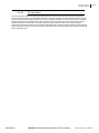
Phasing of the PA modules is tightly controlled at the factory. No phasing of the modules is required in the field. PA modules and IPA (driver modules, used in transmitter cabinets with 10 to 16 PA modules) can be used in any location without re‐phasing. Modified IPA modules, used in PA cabinets with 8 or fewer PA modules, do not require phasing either but can only be used in IPA module slots.
Note
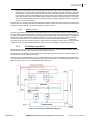
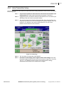
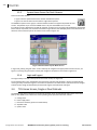
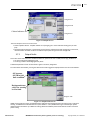
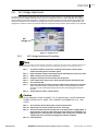
Phasing between cabinets is required to minimize cabinet combiner reject power and it is accomplished
via the GUI screen. Cabinet phase and gain is controlled by adjusting the relative phase and RF output
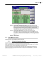
levels of each cabinet using the preamplifiers. See Section 3.7.2 on page 3-18 and Figure 3-18 on page 318 to view adjustment screen.
5.5
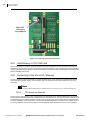
PA & IPA Module Component ID
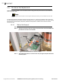
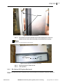
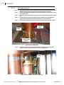
Before attempting PA or IPA module repairs in the field it is important to properly identify the faulty components.
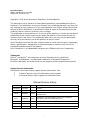
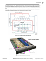
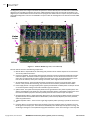
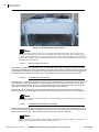
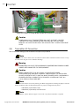
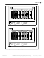
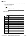
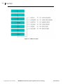
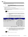
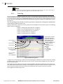
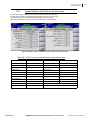
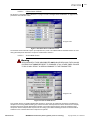
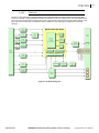
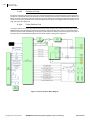
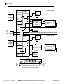
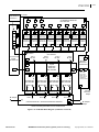
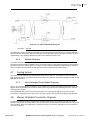
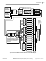
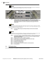
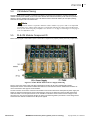
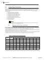
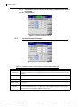
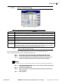
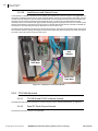
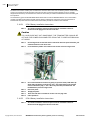
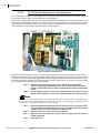
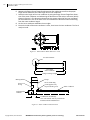
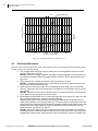
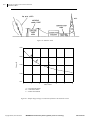
Figure 5-4 PA/IPA Module Pallet and Power Supply Numbering
Figure 5‐4 gives the power supply and pallet identification numbers for PA and unmodified IPA modules. Components that are removed from modified IPA modules are denoted with asterisks. Modified IPA modules are used in transmitters with eight or less PA modules.
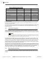
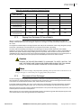
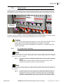
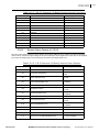
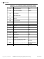
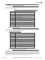
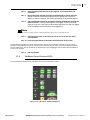
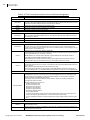
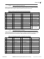
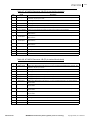
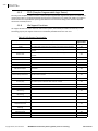
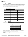
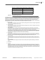
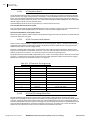
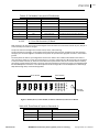
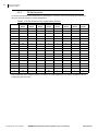
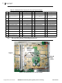
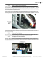
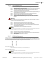
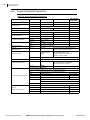
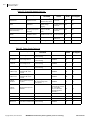
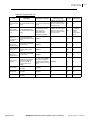
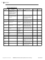
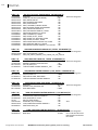
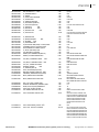
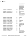
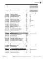
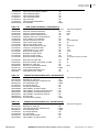
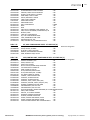
The test connector on the front of the PA or IPA module can be used to determine which pallet or power supply has failed. An optional hand held meter can be attached to the connector to display the status and fault information outlined in Table 5‐2. If the optional meter is not available a multimeter can be used to measure voltages on the connector pins. The normal measured voltages are given in the following table in parenthesis. These voltage values assume that the module is enabled but no RF input is applied.
888‐2628‐300
WARNING: Disconnect primary power prior to servicing.
Copyright ©2013, Harris Broadcast