1
Hardware Setup
(6).
2-11
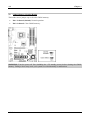
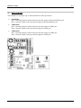
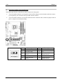
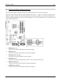
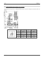
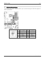
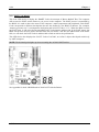
Front Panel Switches & Indicators Headers
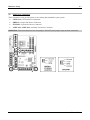
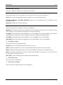
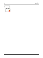
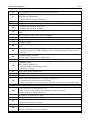
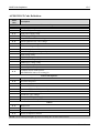
This header is used for connecting switches and LED indicators on the chassis front panel.
Watch the power LED pin position and orientation. The mark “+” align to the pin in the figure below
stands for positive polarity for the LED connection. Please pay attention to connect these headers. A
wrong orientation will only cause the LED not lighting, but a wrong connection of the switches could
cause system malfunction.
•
HLED (Pin 1, 3):
Connects to the HDD LED cable of chassis front panel.
•
RST (Pin 5, 7):
Connects to the Reset Switch cable of chassis front panel.
•
SPK (Pin 15, 17, 19, 21):
Connects to the System Speaker cable of chassis.
•
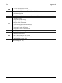
SLED (Pin 2, 4):
Connects to the Suspend LED cable (if there is one) of chassis front panel.
•
PWR-ON (Pin 6, 8):
Connects to the Power Switch cable of chassis front panel.
•
PLED (Pin 16, 18, 20):
Connects to the Power LED cable of chassis front panel.
User’s Manual