1
MXB-250
250,000 BTU BOILER
&
MXB-400
400,000 BTU BOILER
Installation and Operating Instructions
®
Lanair Waste Oil Heaters & Boilers
4109 Capital Circle
Janesville, Wisconsin 53546
608-752-1601
www.lanair.com
®
BEFORE YOU BEGIN INSTALLATION...
Read and understand this manual completely before beginning installation.
Code Requirements
Installation must comply with all state, local and utility codes, laws, regulations and ordinances and CSA standard
B139. When required, installations must conform to A.S.M.E. safety code for controls and safety devices for
automatically fired boilers No. CSD-1.
All electrical wiring must be done by a licensed electrician in accordance with the National Electrical codes latest
edition and all state and local codes.
Rules for Safe Installation and Operation
1. This boiler is for commercial and industrial use only. This unit is not intended for residential use.
2. This boiler must be installed by a licensed HVAC/Hydronic contractor. Installer should be trained and thoroughly
familiar with the installation and operation of oil-fired boilers.
3. Read this owner's manual and the rules for safe operation carefully. Failure to follow the rules of safe operation
and the instructions could cause a malfunction of the boiler and result in death, serious bodily injury, and/or
property damage.
4. Locate the boiler as close to the chimney as practical. Observe the minimum clearances outlined in Fig. 1,
page 8. Remember to allow room for the boiler door to open with the burner mounted.
5. Make sure that the surface on which the boiler is to be installed is capable of supporting the weight of the boiler, burner, and all other equipment supported by that surface.
6. A boiler pad is strongly recommended . This pad is to be made of poured concrete. It should be at least 4 inches
thick and should cover the entire area underneath the boiler (not just the legs).
7. Make sure the location chosen for the boiler will provide adequate air for combustion and ventilation (see Fig. 2,
page 9). Also make sure that fuel and electrical requirements can be satisfied at the boiler location chosen.
8. The heating system design shall not permit the boiler's return water temperature to be lower than 130˚F for a
significant period of time. This will prevent fire side corrosion and insure a long life expectancy for your boiler.
9. Check to make sure you have all the required components needed for proper installation and operation.
10. Check each component for visible damage. If you find a damaged component, contact a Lanair Service
Representative for a replacement. Do not install broken or damaged parts.
11. This boiler is designed to provide economically and environmentally friendly disposal of waste oil. Due to the
nature of the fuel used, this boiler should not be relied upon as the sole source of heat.
12. Read and understand the warranty. Fill out the enclosed warranty card and return within 10 days of purchase.
2
QUESTIONS?... Contact Customer Service at 1-888-370-6531 M-F 8:00 am- 4:15 pm CST
MXB 250/400
250,000/400,000 BTU BOILER
Installation and Operating Instructions
Table of Contents:
Code Requirements and Rules For Safe Installation and Operation . . . . . . . . . . . . . . . . page 2
Sec. 1
General Specifications . . . . . . . . . . . . . . . . . . . . . . . . . . . . . . . . . . . . . . . . . . . . . . . . . . . . . . . . . . . . . . . . . . . page 4
Sec. 2
Typical Boiler Room Layout . . . . . . . . . . . . . . . . . . . . . . . . . . . . . . . . . . . . . . . . . . . . . . . . . . . . . . . . . . . . . page 8
Sec. 3
Boiler Room Air Requirements . . . . . . . . . . . . . . . . . . . . . . . . . . . . . . . . . . . . . . . . . . . . . . . . . . . . . . . . . . page 8
Sec. 4
Chimney/Vent System . . . . . . . . . . . . . . . . . . . . . . . . . . . . . . . . . . . . . . . . . . . . . . . . . . . . . . . . . . . . . . . . . . . page 10
Sec. 5
Draft . . . . . . . . . . . . . . . . . . . . . . . . . . . . . . . . . . . . . . . . . . . . . . . . . . . . . . . . . . . . . . . . . . . . . . . . . . . . . . . . . . . . . . . page 11
Sec. 6
Fuel Supply Tank Piping Installation . . . . . . . . . . . . . . . . . . . . . . . . . . . . . . . . . . . . . . . . . . . . . . . . . . . . page 12
Sec. 7
Fuel Supply Pump/Piping . . . . . . . . . . . . . . . . . . . . . . . . . . . . . . . . . . . . . . . . . . . . . . . . . . . . . . . . . . . . . . . page 13
Sec. 8
Typical Boiler Piping . . . . . . . . . . . . . . . . . . . . . . . . . . . . . . . . . . . . . . . . . . . . . . . . . . . . . . . . . . . . . . . . . . . . . . page 15
Sec. 9
Boiler Installation . . . . . . . . . . . . . . . . . . . . . . . . . . . . . . . . . . . . . . . . . . . . . . . . . . . . . . . . . . . . . . . . . . . . . . . . . page 16
Sec. 10
Boiler Controls and Accessory Location . . . . . . . . . . . . . . . . . . . . . . . . . . . . . . . . . . . . . . . . . . . . . . . . page 20
Sec. 11
Burner Installation . . . . . . . . . . . . . . . . . . . . . . . . . . . . . . . . . . . . . . . . . . . . . . . . . . . . . . . . . . . . . . . . . . . . . . . . page 21
Sec. 12
Electrical Connections/Wiring Diagram . . . . . . . . . . . . . . . . . . . . . . . . . . . . . . . . . . . . . . . . . . . . . . . . page 22
Sec.13
Compressed Air Installation . . . . . . . . . . . . . . . . . . . . . . . . . . . . . . . . . . . . . . . . . . . . . . . . . . . . . . . . . . . . . page 24
Sec.14
Controls . . . . . . . . . . . . . . . . . . . . . . . . . . . . . . . . . . . . . . . . . . . . . . . . . . . . . . . . . . . . . . . . . . . . . . . . . . . . . . . . . . . page 25
Sec.15
Start Up Procedure . . . . . . . . . . . . . . . . . . . . . . . . . . . . . . . . . . . . . . . . . . . . . . . . . . . . . . . . . . . . . . . . . . . . . . . page 26
Sec.16
Priming Fuel Pump . . . . . . . . . . . . . . . . . . . . . . . . . . . . . . . . . . . . . . . . . . . . . . . . . . . . . . . . . . . . . . . . . . . . . . . page 28
Sec.17
Flame Adjustment . . . . . . . . . . . . . . . . . . . . . . . . . . . . . . . . . . . . . . . . . . . . . . . . . . . . . . . . . . . . . . . . . . . . . . . page 29
Sec.18
Maintenance Schedule / Service Adjustments . . . . . . . . . . . . . . . . . . . . . . . . . . . . . . . . . . . . . . . . page 31
Sec.19
Troubleshooting . . . . . . . . . . . . . . . . . . . . . . . . . . . . . . . . . . . . . . . . . . . . . . . . . . . . . . . . . . . . . . . . . . . . . . . . . . page 40
Sec.20
Warranty Certificate . . . . . . . . . . . . . . . . . . . . . . . . . . . . . . . . . . . . . . . . . . . . . . . . . . . . . . . . . . . . . . . . . . . . . . page 42
Sec.21
Burner Reference Diagram . . . . . . . . . . . . . . . . . . . . . . . . . . . . . . . . . . . . . . . . . . . . . . . . . . . . . . . . . . . . . . page 43
Visit our website at: www.lanair.com
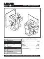
Section 1 - Burner Specifications
2
1
3
6
7
4
5
8
9
10
11
No.
1
2
3
4
5
6
7
8
9
10
11
4
Description
Mounting Plate
Ignitor Transformer
Fuel Line Inlet
Fuel Pressure Gauge
Combustion Air Baffle
View Port
Oil Primary Safety Control
Waste Oil/Fuel Oil Switch
Quick Disconnect Receptacle
Air Supply Inlet
Combustion Blower Motor
Burner Assembly-Performance Ratings
Voltage . . . . . . . . . . . . . . . . . . . . . . . . . . . . . . . . 115 vac
Cycles . . . . . . . . . . . . . . . . . . . . . . . . . . . . . . . . . . . . 60 hz
Total Operating Amperage . . . . . . . . . . . . . . . . . . 4.9
Weight . . . . . . . . . . . . . . . . . . . . . . . . . . . . . . . . . . .31 lbs
Oil Primary . . . . . . . . . . . . . . . . . . . . . . . . . . . . 0.2 amps
Pre-Heater Block . . . . . . . . . . . . . . . . . . . . . . .2.6 amps
Ignitor Transformer . . . . . . . . . . . . . . . . . . . 0.3 amps
QUESTIONS?... Contact Customer Service at 1-888-370-6531 M-F 8:00 am- 4:15 pm CST
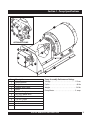
Section 1 - Pump Specifications
2
3
OPTIONAL J-PUMP
8
5
9
4
7
6
1
No.
1
2
3
4
5
6
7
8
9
Description
Pump Platform
Pump Motor
Adapter Shaft Cover
Pump
Pressure Gauge port
Easy Flow Bleed Valve
1/4" NPT Inlet
1/8" NPT Outlet
Adapter Shaft
Pump Assembly-Performance Ratings
Voltage . . . . . . . . . . . . . . . . . . . . . . . . . . . . . . . . 115 vac
Cycles . . . . . . . . . . . . . . . . . . . . . . . . . . . . . . . . . . . . 60 hz
Weight . . . . . . . . . . . . . . . . . . . . . . . . . . . . . . . . . . . 24 lbs
Pump Motor . . . . . . . . . . . . . . . . . . . . . . . . . . . . 5 amps
Visit our website at: www.lanair.com
5
3ECTION"OILER3PECIFICATIONS
$%4!),!
3UPPLY
2ELIEF6ALVE
-8"/),%2
3UPPLY-ANIFOLD
SEE$ETAIL!
%LECTRICAL*UNCTION"OX
&LOW3WITCHNOTINCLUDED
2ETURN
.O
$ESCRIPTION
"URNER!SSEMBLY
6IEW0ORT
%LECTRICAL*UNCTION"OX
(),IMIT3WITCH
2ELIEF6ALVE
#HIMNEY/UTLET
&LOW3WITCHNOTINCLUDED
3UPPLY-ANIFOLD
(I,IMIT3WITCH
4EMPERATURE0RESSURE'AUGE
,OW7ATER#UTOFF3WITCH
/PTIONAL2ELIEF6ALVE,OCATION
"OILER0ERFORMANCE2ATINGS
"URNER&UEL#ONSUMPTION '0(
)NPUT "45
/UTPUT#APACITY "45
.ET2ATING7ATER"45(2 "45
!PPROX $RY7EIGHT LBS
6ENT#ONNECT DIA
7ATER#ONTENT GAL
-AX/PERATING7ATER0RESSURE 03)
15%34)/.3 #ONTACT#USTOMER3ERVICEAT1-888-370-6531-&AM15PM#34
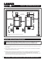
Section 1 - Boiler Specifications
TOP
10
11
REAR
12
Clean-Out
Port
Clean-Out
Port
14
13
SIDE
FRONT
9
8
2-1/2” MPT Supply
1
7
2-1/2” FPT Return
4
2
5
6
3
No.
1
2
3
4
5
6
Dimension
400
250
36"
36"
33"
33"
73-3/8" 63-3/8"
12"
12"
42"
52"
8"
8"
No.
7
8
9
10
11
12
Dimension
3/4"
9-3/8"
7-3/4" oc
18" oc
5" oc
29-1/2" oc
No.
13
14
Dimension
4" oc
20" oc
Visit our website at: www.lanair.com
7
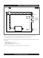
3ECTION4YPICAL"OILER2OOM,AYOUT
v
v
v-IN
"OILER6ENT
#ONNECTIONS
v"OILER
3UPPLY#ONNECTION
h
h
#,
#,
v
-8"
v
vMIN
v
-8"
v
v
v
#,
$IMENSIONASPERJOBSPECIFICATIONSANDLOCALCODES
&IGURE
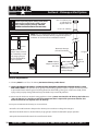
3ECTION"OILER2OOM!IR2EQUIREMENTS
!
7!2.).' &AILURETOPROVIDEANADEQUATESUPPLYOFFRESHAIRFORCOMBUSTIONWILLRESULT
INHAZARDOUSOPERATINGCONDITIONS $ONOTUSEANEXHAUSTFANINTHEBOILERROOM
4OENSURESAFEEFFICIENTOPERATION THEBOILERSYSTEMMUSTBESUPPLIEDWITHSUFFICIENTAIRFORCOMBUSTIONANDVENTILA
TIONSEE&IG 5NLESSPROPERLYCONTROLLED AVOIDTHEUSEOFFORCEDVENTILATION SINCEITCANCREATEANUNDESIRABLEPRESSUREDIFFEREN
TIALBETWEENTHEBOILERROOMANDAIRSOURCE
!LLBOILERSLOCATEDINCONFINEDROOMSSHOULDHAVEFREEACCESSTOVENTILATIONANDCOMBUSTIONAIRFROMTWOPERMA
NENTOPENINGS /NEOPENINGSHOULDTERMINATEWITHINOFTHECEILING THEOTHERWITHINFROMTHEFLOOR
SEE&IG %ACHOPENINGSHALLHAVEATLEASTSQ INCHFREEAREAPER"45(2OFBURNERINPUT /PENINGSSHOULD
FREELYCONNECTWITHAREASHAVINGADEQUATEINFILTRATIONOFOUTSIDEAIR
15%34)/.3 #ONTACT#USTOMER3ERVICEAT1-888-370-6531-&AM15PM#34
3ECTION"OILER2OOM!IR2EQUIREMENTS
&IGURE
-AXIMUM
,OUVERED
OPENINGSFOR
VENTILATION
COMBUSTION
-AXIMUM
7HENAIRCOMESDIRECTLYFROMOUTDOORS AGAINUSETWOOPENINGSASEXPLAINEDONPAGEANDABOVEEXCEPT
s!LLDUCTINGSHALLBETHESAMESIZEASOPENINGBUTNOLESSTHANXORSQUAREINCHES
2EMEMBERTOCOMPENSATEFORLOUVERBLOCKAGEWHENCALCULATINGFREEAIR 2EFERTOMANUFACTURERgSINSTRUCTIONSORUSETHIS
GENERALGUIDE
7//$,/56%23!LLOWFREEAIR
-%4!,,/56%23/2'2),,%3 !LLOWFREEAIR
!NYLOUVERDAMPERSHOULDLOCKOPENOROPENAUTOMATICALLYWHENTHEBOILEROPERATES
6ISITOURWEBSITEAT WWWLANAIRCOM
3ECTION#HIMNEYOR6ENT3YSTEM
!
&AILURETOPROVIDEPROPERVENTINGOFTHEBOILER
EXHAUSTGASESCOULDRESULTINDEATH SERIOUS
INJURY ANDORPROPERTYDAMAGE &/,,/7
#()-.%9-!.5&!#452%23).3425#4)/.3
#LASS!#HIMNEY#AP
gTALLERTHANANY
OBJECTSWITHINg
#LASS!#HIMNEY
./4% #LASS!COMPONENTSREQUIREACLEARANCEFROMCOM
BUSTIBLEMATERIALS !LLOTHERCHIMNEYCOMPONENTSREQUIREA
MINIMUMCLEARANCEFROMCOMBUSTIBLEMATERIALS
(/2):/.4!,
6%24)#!,
"AROMETRIC$AMPER
FROMBOILER
./4% "AROMETRIC
$AMPERMAYBEMOUNT
EDHORIZONTALLYORVERTI
CALLY !NGLEGATEPINS
MUSTBEHORIZONTALFOR
PROPEROPERATION
./4% #HIMNEY
ADAPTERISINCLUDED
0.
g4YPICAL
#APPED
#LEANOUT
4EE
./4% (ORIZONTALPIPE
MUSTHAVEARISE
PERFOOTOFLENGTH
&IGURE
'ENERAL2EQUIREMENTS
#HIMNEY -534 BEAv #LASS!CHIMNEY $O.OT5SECHIMNEYSMALLERTHANv
).34!,,!4)/.-534"%$/.%"9!,)#%.3%$(6!#(9$2/.)##/.42!#4/2&!-),)!27)4(!,,34!4%
!.$,/#!,#/$%3 3AFEOPERATIONOFANYGRAVITYVENTEDHEATINGAPPLIANCEREQUIRESAPROPERAIRMAKEUPSYSTEM
TOPREVENTTHEHEATEREXHAUSTGASESFROMBEINGDRAWNINTOTHEBUILDING 4HESEGASESCOULDCAUSEDEATH SERIOUS
INJURY ANDORPROPERTYDAMAGE %XHAUSTFANS PAINTBOOTHSMAYCAUSEDRAFTPROBLEMS
.EVERVENTTHISBOILERINTOANOTHERHEATINGAPPLIANCESCHIMNEY .EVERVENTINTO@#LASS"v CHIMNEY 'ASBOILERSUSE
h#LASS"v CHIMNEY ITISRATEDFORAMUCHLOWERTEMPERATURETHANISREQUIREDFORYOURWASTEOILBOILER 4HIS
BOILERMUSTHAVEITSOWNSEPARATEh#LASS!v CHIMNEY
)NSPECTANDMAINTAINTHECHIMNEYONANANNUALBASIS
)NSTALLA5, LISTEDBAROMETRICDAMPERINTHECHIMNEY $ONOTREDUCEORENLARGETHEVENTPIPE
0OSITIONTHEDRAFTCONTROLASSHOWN #HIMNEYANGLEGATEPINSMUSTBEHORIZONTALFORPROPEROPERATION
+EEPTHEBAROMETRICDRAFTCONTROLATLEASTv FROMTHEBOILER
15%34)/.3 #ONTACT#USTOMER3ERVICEAT1-888-370-6531-&AM15PM#34
Section 4 - Chimney or Vent System
8. Do not use more than one 90° elbow. Each 90° elbow equals a 10’ run of chimney. The maximum run for the chimney
connector is 30’.
9. Secure all connections in the chimney connector with 3 screws per joint.
10. The chimney connector clearance to any combustible material is 18”. The Class "A” chimney clearance to any combustible is 2”. FOLLOW THE CHIMNEY MANUFACTURER’S INSTRUCTIONS.
11. Do not install heat re-claimers, manual draft controls, or any other type of restrictive control in the chimney.
12. Install a 8” diameter clean out tee with a cap, at the transition of the chimney.
FOLLOW CHIMNEY MANUFACTURER’S INSTRUCTIONS.
13. Use a 8” inside diameter “Class A” insulated chimney pipe to vent exhaust gases through wall, ceilings, attics, roofs,
combustibles, etc..
14. Vent chimney at least 3 feet above the roof and at least 3 feet higher than any portion of the building, roof, or
obstruction within 10 feet of the chimney.
15. The chimney cap should be at least 3’ above the roof exit.
16. Do not use a rotating chimney cap. Use a non-restrictive “Class A” cap made for the type of “Class A” chimney you are
using. FOLLOW CHIMNEY MANUFACTURER’S INSTRUCTIONS.
17. The chimney must be capable of producing a negative -.02 W.C. draft when cold and -.06 W.C. draft when hot. Refer
to Section 5 Draft Instructions.
18. If you are unable to attain the proper draft, check for exhaust fans in the building. To test if there is a problem, open
an overhead door and see if you now have the proper draft. You may have to add one or more sections of “Class A”
chimney to the roof to get the proper draft.
19. The boiler and chimney must be installed in accordance with all state and local codes. The boiler must be
installed by a licensed HVAC/Hydronics contractor in accordance with the specifications listed in this manual.
The chimney must be installed per the chimney manufacturers instruction. Use “Class A” chimney only.
!
WARNING: FOLLOW THE CHIMNEY MANUFACTURER’S INSTALLATION INSTRUCTIONS AS
WELL AS STATE AND LOCAL FIRE CODES.
Section 5 - Draft
The boiler should have a (negative) -.02 draft reading when cold, and a (negative) -.06 when hot. Check the boiler when it
is running after 45 minutes. If the reading is not what it should be, adjust the barometric damper according to the
instructions provided with the damper. The draft reading should be taken with a manometer. Consult your heating contractor, or manometers can be purchased from the Lanair Customer Service Department 800-753-1601.
Visit our website at: www.lanair.com
11
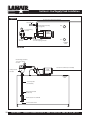
Section 6 - Fuel Supply Tank Installation
Figure 4
3/8” Fuel Line To Burner (not included)
3/8” Copper
Tube P/N 9182
Fuel Regulator Assembly
(see page 14)
Vent
1“ x 1/2” bushing
P/N 8904
PUMP
ASSEMBLY
1/4” Nipple P/N 8647
1/4” x 1/2” Coupling P/N 8558
1“ x 1/2” bushing
P/N 8904
Fill
STORAGE
TANK
TOP VIEW
Vacuum Gauge P/N 8398
1/2” x 1/4” x 1/4” Tee
P/N 9412
3/8” Fuel Line To Burner (not included)
PUMP
ASSEMBLY
Primary Strainer
P/N 9807
STORAGE
TANK
1/2” pick-up tube
(not included)
Check Valve P/N 8662
(inside tank)
Strainer Suction Line P/N 8748
6“ from bottom of tank
12
QUESTIONS?... Contact Customer Service at 1-888-370-6531 M-F 8:00 am- 4:15 pm CST
Section 7 - Fuel Supply Pump/ Piping
General Requirements - Fuel Tank
1. The fuel supply tank and supply lines must be installed in accordance with the National Fire Protection Association
requirements, as well as state and local ordinances.
2. Regulations require oil storage tanks located inside a building not exceed 275 gallons individually and are not to
exceed 550 gallons in one building. Check state and local codes.
3. Oil storage tank must be inside the building as close to the boiler as possible (max. 25 feet) to avoid flow problems.
4. Pitch the fuel supply 2º with the drain valve at the lowest end to drain off water and sludge. Sludge may have to
manually be removed.
5. Some ordinances may require the fuel supply tank to be vented to outside, and above the roofline. Check State and
Local codes. Keep the vent clear.
6. Install the fuel tank fill pipe at the end of the tank and above the drain.
7. Label the fuel tank for the recommended fuels.
8. Strain all fuel with a 50 X 50 mesh strainer before putting fuel into the tank.
9.
When filling the fuel tank with a motorized pump, never leave unattended to prevent over filling and/or spillage.
10. Keep fill cap on the fuel tank when not filling.
General Requirements - Fuel Pump/Piping
1. Mount the fuel supply pump in a horizontal position (shaft horizontal) near the fuel supply tank.
2. The oil pump has a maximum suction lift of 14 feet. Suction lift is the length of pipe run from the bottom of the
pick up strainer to the fuel supply pump.
3. The fuel pump/motor are for indoor use only.
4.
The fuel pump contains an internal strainer that periodically needs to be cleaned (see Section 18, page 33). This
internal strainer is mounted behind the pump cover. Before removing the pump cover make sure you have a new
gasket on hand. Contact the Lanair Customer Service Department for the proper gasket for your model of pump, at
800-753-1601.
5. Install the suction supply line from the inlet side of the fuel pump into the fuel tank opposite the drain.
6. Install a 1/2” inside diameter (.493) steel pipe, or 1/2” outside diameter copper throughout the suction supply line
and pick up tube. The use of smaller line, or rubber, plastic or hydraulic line is unsafe and will void your warranty.
7. Use thread sealing compound on all pipe thread connections. DO NOT USE TEFLON TAPE.
8. Install the suction line strainer in the suction line. Make sure the suction line strainer is 6” off the bottom of the tank.
The suction line strainer may be mounted horizontally or vertically. Consider accessibility.
9. Install a pipe union between the suction line strainer and the pick up tube to allow for service on the pick up tube.
Visit our website at: www.lanair.com
13
Section 7 - Fuel Supply Pump/ Piping
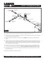
NOTE: This item comes pre-assembled from the factory.
FUEL LINE
TO BURNER
3/8” x 1/4’” NPT
P/N 8939
Tee
P/N 8909
Fuel Regulator
P/N 8460
Fuel Relief Valve
P/N 8462
Close Nipple
P/N 8647
Bushing P/N 8908
RETURN LINE
TO TANK
3/8” x 1/4’” NPT
P/N 8939
Nipple P/N 8915
Figure 5
10. Install the check valve (arrow facing towards the pump) on the bottom of the pick up tube.
11. Install a vacuum gauge (included, P/N 8398) in the suction line. This gauge will indicate when service is needed on
the strainer, pump, connections, or fuel level.
12. Install fuel regulator and fuel relief valve assembly (see Fig 5). NOTE: This item comes pre-assembled from the
factory.
13. Install the 3/8" diameter copper line from the fuel relief valve to the fuel supply tank. Do not allow this line to protrude into the tank more that 1”. This line should not be submerged in oil. Failure to install this line properly will
result in damage to your boiler, and will void your warranty. The use of smaller line, or rubber, plastic or hydraulic
line is unsafe and will void your warranty.
14. Install the fuel supply line from the fuel regulator/ relief valve assembly to the inlet port on the left side of the
burner using 3/8” outside diameter copper tubing. NOTE: THE MAXIMUM DISTANCE OF THIS LINE IS 25 FEET.
15. If using copper line on the suction side of the pump, use flare fittings. Compression fittings may be used on the
push side of the pump.
16. Keep the fuel supply lines 1” off any outside walls.
14
QUESTIONS?... Contact Customer Service at 1-888-370-6531 M-F 8:00 am- 4:15 pm CST
3ECTION4YPICAL"OILER0IPING
&IGURE 3INGLE"OILER0IPINGWITH"LEND0UMP
!
!44%.4)/. (EATINGSYSTEMDESIGNANDBURNEROPER
ATIONMUSTINCORPORATEINTERLOCKTOPREVENTBURNER
FROMFIRINGWHENBOILERHASNOSYSTEMWATERFLOW
!
-INIMUM2ETURN7ATER4EMPERATURE &
!IR3EPARATOR
!MTROL
!IR%LIMINATOR
OR%QUAL
3YSTEM3UPPLY
3YSTEM#IRCULATOR
"LEND
0UMP
#HECK
6ALVE
0RESSURE2EDUCTION6ALVE
"ACKFLOW0REVENTER
%XPANSION
4ANK
&ROM#ITY
7ATER3UPPLY
'0-"LEND0UMPSHOULDBEUSED
3YSTEM
2ETURN
&IGURE" 3INGLEOR-ULTIPLE"OILER0IPINGFOR0RIMARY3ECONDARY0UMPING
!IR3EPARATOR
"LEND
0UMP
!MTROL
!IR%LIMINATOR
OR%QUAL
3YSTEM3UPPLY
#HECK
6ALVE
3YSTEM#IRCULATOR
AX
v
"LEND
0UMP
"ACKFLOW0REVENTER
&ROM#ITY
7ATER3UPPLY
#HECK
6ALVE
A
v
3YSTEM2ETURN
0RESSURE2EDUCTION6ALVE
%XPANSION
4ANK
X
./4%3
s3IZESECONDARY0UMP'0-ATGROSSBOILEROUTPUT
FORAv DROP
s7HENCALCULATINGPUMPHEAD THEMAXIMUM
BOILERRESISTANCEFORANYBOILERWILLNOTEXCEED
v IN7# OFHEAD
6ISITOURWEBSITEAT WWWLANAIRCOM
Section 9 - Boiler Installation
!
All MX Series boilers are shipped with the boiler sections assembled and hydrostatically
tested to A.S.M.E. at the factory. Inspect boiler for any visible damage before beginning
installation.
Inspect Shipment
Any claims for damage or shortage must be filed against carrier or consignee. No claims for variances from, or shortages
in orders, will be considered unless presented 7 days after receipt of goods.
Boiler shipment comes in two separate pallets.
1. Wood pallet with:
s Boiler block with insert installed
s Box of jacket parts
s Box marked #3 (Burner Assembly)
a) Complete Lanair MXB Burner assembly
b) Secondary Air Filter/Regulator
s Box marked #4 (Accessories Box)
a) Oil filter, oil pressure gauge, oil supply line relief valve, and regulator assembly, plumbing kit and Instruction
Manual/Warranty Card Packet
2. Boxes in the boiler chamber
s Box marked #1 (Manifold Box)
a) Supply and return manifold, gaskets, 3/4” x 6” pipe, mounting studs, washers and nuts
b) Return diffuser and gaskets
c) Two (2) 3/4" male x female extension couplings for optional controls
s Box marked #2 (Controls Box)
a) High Limit with 3/4" well and capillary clip
b) Temperature/Pressure Gauge
c) Relief Valve
d) Flame sight assembly
e) Four (4) spacers to secure back jacket panel
f ) Burner mounting hardware
g) 1” to 3/4” reducer
h) Insulation and Mortar
s Box marked #5 (Low Water Cut Out)
s Chimney Adapter
Placement
1. Move the boiler (in the crate) as close as possible to its final location. Boiler must be positioned on a proper load
bearing concrete pad or floor. See Fig. 1, page 8 for typical boiler room layout.
2. Remove the lag screws (2) holding the rear feet to the skid.
3. Remove the front jacket panel. Cut the banding holding the front of the boiler to the skid.
4. Carefully move the boiler into its final position.
!
16
INSTALLATION MUST BE DONE BY A LICENSED HVAC/HYDRONIC CONTRACTOR
FAMILIAR WITH ALL STATE AND LOCAL CODES.
QUESTIONS?... Contact Customer Service at 1-888-370-6531 M-F 8:00 am- 4:15 pm CST
3ECTION"OILER)NSTALLATION
!
.OTE 4HREADSUSEDONTHESTUDSISMETRIC !NYATTEMPTTOUSESTANDARD%NGLISHTHREAD
EDSTUDSINPLACEOFTHOSESUPPLIEDWILLDAMAGETHEBOILERBLOCK
&IGURE
MMXMMSTUDS
'ASKET
MMWASHERS
4/0 /& "/),%2
MMNUT
3UPPLY-ANIFOLD
-ANIFOLDAND$IFFUSER)NSTALLATION
!TTACHSUPPLYMANIFOLDASINDICATEDIN&IG )NSTALLRETURNPORTDIFFUSERANDATTACHRETURNFLANGEASSHOWNIN&IG ./4% -AKESUREDIFFUSERSLOTSFACEUPWARDSEE&IG &IGURE
MMXMMSTUDS
'ASKET
'ASKET
$IFFUSER
MMWASHERS
MMNUT
2ETURN&LANGE
"/44/-/& "/),%2
6ISITOURWEBSITEAT WWWLANAIRCOM
Section 9 - Boiler Installation
Figure 9
086
038
036
094
033
060
030
040
018
043
018
093
041
!
ATTENTION: DO NOT INSTALL THE BOILER JACKET WITHOUT FIRST ATTACHING THE
SUPPLY MANIFOLD AND DIFFUSER (SEE PAGE 17).
PARTS LIST
18
018 HINGE BRACKET (factory mounted to boiler)
041 UPPER FRONT TRIM PANEL
030 ADDITIONAL INSULATION
043 SETSCREW AF-17 AND SPACER (4 required)
033 CENTER PANEL
060 REAR INSULATING MAT (2 PIECES)
036 RIGHT REAR PANEL
086 TOP PANEL
038 LEFT REAR PANEL
093 RIGHT SIDE PANEL
040 INSULATING MAT FOR BOILER SHELL (FOIL OUT)
094 LEFT SIDE PANEL
QUESTIONS?... Contact Customer Service at 1-888-370-6531 M-F 8:00 am- 4:15 pm CST
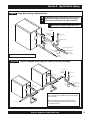
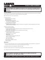
Section 9 - Boiler Installation
Boiler Jacket Installation
1.
Screw the four (4) jacket extensions (043) into the the
four outer holes in the corners of the rear boiler section.
Securely tighten the jacket extensions. Check other
bolts on the rear panel and tighten if necessary.
2.
Place the large wrap-around insulation blanket (040)
over the boiler block. NOTE: The aluminum foil side of
the blanket should be facing out.
3.
Place smaller piece of insulation (030) on top of the
insulation blanket. This will provide extra insulation on
the top of the boiler block.
4.
Remove flue collector clean-out covers (see illustration
on page 7 for location).
!
ATTENTION: THIS BOILER REQUIRES A LINER
(INCLUDED) FOR OPERATION. DO NOT
OPERATE BOILER WITHOUT LINER IN PLACE.
5.
Place rear insulation (060) on the rear panel. The holes
of the insulation should align with the clean-out ports
and the jacket extensions (043). Compress insulation
until the jacket extensions (043) protrude. NOTE: The rear insulation is two separate pieces (right and left) Position
with the aluminum foil side of the insulation facing out.
6.
Align the right rear jacket panel (036) to the jacket extensions (043) and attach using two (2) M6 x 10 pan head
screws provided. Align the left rear jacket panel (038) to the jacket extensions (043) and attach using two (2) M6 x
10 pan head screws provided. Align the corresponding holes of the right and left rear jacket panels and secure
using five (5) sheet metal screws provided.
7.
Re-attach the flue collector clean-out covers. NOTE: Do not over tighten bolts of the clean-out covers. Over tightening may crack or break the covers.
8.
Attach the right (093) and left (094) jacket panels. Each panel attaches to the unit using the hooks on the factoryinstalled hinge brackets (018) at the front of the unit and the holes in the previously mounted rear panels.
9.
Place the center panel (033), with flange edge down,
between side panels.
10.
11.
Attach the upper front trim panel (041) between the
right (093) and left (094) side panels. The front panel has
hooks which are inserted into slots in the front of the
side panels.
Lens
Cap
Gasket
Align the hooks of the top panel (086) with those of slots
on the top of the side panels. Place top panel between
side panels and slide forward to lock in position.
Sight Glass Installation
1.
Remove the sight glass plug on the door of the unit.
2.
Install sight glass assembly. Hand tighten (Fig. 10).
Figure 10
Visit our website at: www.lanair.com
19
3ECTION"OILER#ONTROLSAND!CCESSORY,OCATION
&IGURE
PRESSURERELIEFVALVE
-8"/),%2
!QUASTAT
%LECTRICAL*UNCTION"OX
"URNER3ERVICE3WITCH
!
).34!,,!4)/.-534"%$/.%"9!,)#%.3%$(6!#(9$2/.)##/.42!#4/2
&!-),)!27)4(!,,34!4%!.$,/#!,#/$%3
"OILER#ONTROLSAND!CCESSORY,OCATION
2EMOVETHETOPOFTHEBOILERJACKET )NSTALL
XRELIEFVALVEPIPETOTHETOPOFTHE
UNITASINDICATEDIN&IG 0IPEMOUNTSTO
THEHOLEATTHETOPREAROFTHEBOILER
BLOCK
)NSERTTHESENSOROFTHEAQUASTATTHROUGHTHE
SIDEOFTHEBOILERJACKET -OUNTTHEAQUASTAT
TOTHESIDEOFTHEBOILERASINDICATEDIN&IG
&IGURE
PRESSURERELIEFVALVE
AQUASTATSENSOR
./4% )NSTALL !&4%2
BOILERJACKETHAS
BEENREINSTALLED
SENSORHOUSING
XPIPE
)NSERTTOREDUCERTOBOILERTOPAND
TIGHTEN )NSERTSENSORHOUSINGINTOREDUCER
ANDTIGHTEN )NSERTTHESENSORINTOTHEHOUS
ING ./4% 3ENSORMUSTBEFULLYSEATEDFOR
PROPEROPERATION
2EPLACETHETOPOFTHEBOILERJACKET
!TTACHTHEPRESSURERELIEFVALVETOTHEPREVI
OUSLYATTACHEDXPIPEANDTIGHTEN
v TOREDUCER
15%34)/.3 #ONTACT#USTOMER3ERVICEAT-&M#34
3ECTION"OILER#ONTROLSAND!CCESSORY,OCATION
!
$ISCHARGEPIPINGFROMPRESSURERELIEFVALVEMUSTBEPIPEDTOADRAINORMUSTTERMINATE
ABOVEFLOORTOAVOIDDAMAGETOTHESTRUCTUREORPERSONALINJURY )TMUST./4 BEPIPEDTO
APOINTWHEREFREEZINGMIGHTOCCUR
LOWWATERCUTOUT
&IGURE
)NSTALLDISCHARGEPIPINGFROMPRES
SURERELIEFVALVE
)NSTALLPIPEEXTENSIONTOSUP
PLYMANIFOLD !TTACHSENSORHOUS
INGTOTHEEXTENSION )NSERTHILIMIT
SENSORINTOHOUSINGANDATTACHTO
THESENSORHOUSING
!TTACHTEMPERATUREPRESSURE
GAUGEANDLOWWATERCUTOUTTO
THESUPPLYMANIFOLDSEE&IG )NSERTPLUGNOTINCLUDEDINTO
TOPOFMANIFOLDANDTIGHTEN
PLUGNOTINCLUDED
SUPPLYMANIFOLD
PIPEEXTENSION
HILIMITSWITCH
SENSOR
HOUSING
TEMPERATUREPRESSURE
GAUGE
!
)FABLENDPUMPISNOTUSED CONSULTYOURLICENSEDHYDRONICCONTRACTORREGARDINGSYSTEM
DESIGN-INIMUMRETURNWATERREQUIRED
3ECTION"URNER)NSTALLATION
&IGURE
WASHER
"URNER)NSTALLATION
5NPACKTHEBURNERANDINSPECTFOR
ANYSIGNSOFDAMAGE
2EMOVECARDBOARDINSERTFROM
DOORFRONT
0OSITIONTHEBURNERTOTHEDOOROF
THEBOILERANDATTACHUSINGFOUR
BOLTSANDWASHERSPROVIDED
SEE&IG !FTERTHEBURNERISMOUNTEDOPEN
THEBURNERDOORANDSEALTHEVOID
BETWEENTHEBURNERDOORANDTHE
BLASTTUBEOFTHEBURNERWITHTHE
INSULATIONANDMORTARSUPPLIED
WITHTHEBOILER
BOLT
6ISITOURWEBSITEAT WWWLANAIRCOM
Section 12 - Electrical Connections
! CAUTION: HAZARD OF ELECTRICAL SHOCK!
Main Electrical Installation
1. All wiring must comply with the National Electrical Code. State and Local Ordinances, and be wired by a qualified
electrician.
2. Electrical service MUST be connected to a separate 20 AMP, 115 VAC, 60 HZ single phase circuit.
3. Electrical service connections are made in the electrical junction box on side of the boiler.
4. The boiler must have a safety equipment ground from the main electrical service, stranded 12 GA minimum.
5. The electrical conductors for electrical service to the heater MUST be stranded 12 GA minimum.
6. Install a manual service disconnect near the heater, and label its function.
7. The supply voltage must be maintained at a minimum 110 VAC.
8. The electrical conductors from the main electrical service must be within approved conduit.
9. Keep all electrical conductors and conduit away from the chimney connector as well as any other hot surfaces. Refer
to Figure 15, Wiring Diagram for color code, etc. Keep the power off until the heater is ready to be started. Refer to
Section 13 Start Up Procedure.
Fuel Supply Pump Electrical Installation
1. All wiring must comply with the National Electrical Code, State and Local Ordinances, and be wired by a qualified
electrician.
2. The electrical conductors to the fuel pump motor MUST be stranded 14 GA minimum.
3. The electrical service connections for the fuel pump motor are made in the electrical junction box on the side of the
boiler.
4. The pump motor MUST have a safety equipment ground from the main electrical service, stranded 12 GA minimum.
5. The electrical conductors from the electrical junction box to the pump motor must be within approved conduit.
6. Keep all electrical conductors and conduit away from the chimney connector as well as any other hot surfaces. Refer
to Figure 15 Wiring Diagram for color code, etc. Keep the power off until the boiler is ready to be started. Refer to
Section 13 Start Up Procedure.
Hi-Limit Switch and Manifold Controls Electrical Installation
!
ATTENTION! DUE TO VARYING SYSTEM DESIGNS, ONLY A CERTIFIED HVAC/HYDRONICS
INSTALLER CAN DETERMINE THE PROPER WIRING OF THESE COMPONENTS.
All wiring must comply with the National Electrical Code. State and Local Ordinances, and be wired by a qualified
electrician.
22
QUESTIONS?... Contact Customer Service at 1-888-370-6531 M-F 8:00 am- 4:15 pm CST
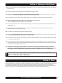
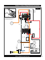
/2!.'%
-!.5!,
2%3%4
3.!0
$)3+
/),02)-!29
7()4%
7()4%
$%0%.$).'/.).34!,,!4)/.
",!#+
9%,,/7
9%,,/7
&&44
",!#+
!)2
02%(%!4%2
7()4%
6ISITOURWEBSITEAT WWWLANAIRCOM
",5%
7()4%
02%(%!4%2
37)4#(
7()4%
7()4%
4 2 !. 3& / 2 - % 2
#/-"534)/.
",/7%2
/),
02%(%!4%2
7()4%
",5%./453%$
4/4(%2-/34!4
/2*5-0%2
/2!.'%
",!#+
2%$
/2!.' %
0520,%
7()4%
7()4%
7()4%
!) 2
3/,%./)$
05-0
-/4/2
-!).0/7%2).
6/,4
2EMOVEWIRESFROMTHEBLOCKBYINSERT
INGAFLATTIPSCREWDRIVERINTOTHETOP
SLOT 0USHTIPALLTHEWAYDOWNAND
PUSHFORWARD 2EMOVEWIRE
2%$
#!$
# %,,
4/ (),)-)4
37)4#(!.$
3500,9-!.)&/,$
#/.42/,3
&2/- (),)-)4
37)4#(!.$
3500,9-!.)&/,$
#/.42/,3
7()4%
2%$
/ 2 !. ' %
3ECTION"URNER0UMP%LECTRICAL#ONNECTIONS
&IGURE
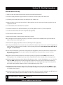
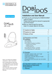
Section 13 - Compressed Air Installation
Compressed Air Supply Installation
1. Install an air pressure supply line connection to the air filter/regulator.
2. The air supply source must be capable of producing 1.0 CFM @ 100 PSI.
3. Install a shut off valve in the air supply line for service.
4. Install a primary air filter/regulator with a gauge (capable of reading line pressure) in the air supply line prior to
the air filter/regulator mounted on the furnace. THE PRIMARY AIR FILTER/REGULATOR IS NOT SUPPLIED WITH
THE BOILER.
5. If the primary air regulator does not have a filter with a bowl, a condensate drain leg must be installed in the air supply line.
6. Install a quick disconnect at the air filter/regulator on the boiler for service.
7. For the ease of installation install a flexible air line (.250 I.D. minimum) from the quick disconnect to the primary air
regulator.
8. The air supply line must be pitched upward from the primary regulator to the boiler to prevent condensation from
entering your burner.
9. Open all air shut off valves, and set the primary air regulator at 30 PSI.
10. Set the secondary air filter/regulator to 15 PSI.
Figure 16
to air supply
secondary air filter/regulator (included)
24
primary air
filter/regulator
(not included)
QUESTIONS?... Contact Customer Service at 1-888-370-6531 M-F 8:00 am- 4:15 pm CST
Section 14 - Controls
Burner Controls and Operation
• Oil Primary Safety Control/Cad Cell:
The oil primary control is mounted on top of the burner’s electrical box. When the thermostat calls for heat the oil
primary control starts the burner by switching on the air solenoid valve, ignition transformer, combustion air blower,
and the fuel pump. The oil primary control works in conjunction with the cadmium sulfide cell (cad cell). The cad cell
is mounted inside the burner cover, and faces the flame. The cad cell monitors the light level inside the combustion
chamber to insure there is a flame present. If there is a loss of flame the primary control will go into its recycle
mode. After 1-2 minutes the primary control will restart the burner. When this happens if there is a flame present,
the burner will continue to function. If on start up no flame is established in 30 seconds the primary control will lock
out. CAUTION: Do not press the reset button more than twice. If the burner fails to start refer to Section 19, Trouble
Shooting.
• Barometric Draft Control:
The Barometric Draft Control automatically maintains a pre-set chimney draft, and is located in the chimney connector (see page 10, Fig. 3). NOTE: The draft must be set/checked using a manometer.
• Air Filter/Regulator:
The Air Filter/Regulator performs two functions: 1. It removes condensation and dirt from the air. 2. It controls the
amount of air pressure reaching the nozzle and air operated fuel valve. The Air/Filter Regulator is mounted on the
cabinet near the burner.
• Electric Air Solenoid Valve:
The Electric Air Solenoid Valve is controlled by the Oil Primary Control. It acts as a shut-off valve, (it’s open during
operation, and closed when the burner is off ). The Electric Air Solenoid Valve is located inside of the burner’s electrical box.
• Air Operated Fuel Valve:
The Air Operated Fuel Valve controls fuel flow to the nozzle. When the Electric Air Solenoid Valve opens and air pressure pushes on the fuel valve diaphragm, the plunger moves off the nozzle seat allowing fuel to enter the nozzle.
The Air Operated Fuel Valve is located on the back of the air pre-heater.
• Air/Oil Pre-heater:
The Air/Oil pre-heater is an assembly that preheats the atomizing air and fuel to a predetermined temperature to
properly combust used oil. The Air/Oil pre-heater is located in the burner.
• Snap Disc Assembly:
The Snap Disc accurately controls the temperature of the air/oil pre-heater assembly with two resistance type cartridge-heating elements. The Snap Disc is mounted on the oil pre-heater inside the burner.
• Nozzle:
The Nozzle uses air pressure to help pull fuel through its small orifice, and to atomize the fuel for proper combustion. The Nozzle is located on the end of the air pre-heater opposite the fuel valve. Replace the Nozzle annually, as
they are prone to wear by contaminants in waste oil/used oil.
Fuel Pump Controls and Operation
• Fuel Supply Pump:
The Fuel Supply Pump pumps fuel from your oil storage tank to the burner. The Fuel Supply Pump should be located as close to the fuel supply tank as possible. The Fuel Supply Pump must be mounted horizontally (Shaft). See
page 12, Fig. 4.
Visit our website at: www.lanair.com
25
3ECTION#ONTROLS
&UEL0UMP#ONTROLSAND/PERATION
s &UEL2EGULATOR
!&UELREGULATORISUSEDTOADJUSTTHEFUELPRESSUREOFWASTEOILTOTHEBURNER
s &UEL2ELIEF6ALVE
4HEFUELRELIEFVALVEPREVENTSEXCESSPRESSUREBUILDUPINTHEFUELLINEUPONBURNERSHUTDOWN
"OILER#ONTROLSAND/PERATION
s (I,IMIT3WITCH
(ILIMITSWITCHESAREIMMERSIONTYPEDEVICESFORREGULATINGTHETEMPERATUREOFLIQUIDSINABOILERWHERETEMPERATURE
CONTROLISREQUIRED 4HE(ILIMITSWITCHISMOUNTEDTOTHESUPPLYMANIFOLDATTHEREAROFTHEBOILERSEEPAGEFOR
DETAILS
s ,OW7ATER#UT/UT
4HELOWWATERCUTOUTSWITCHISLOCATEDONTHESUPPLYMANIFOLDATTHEREAROFTHEBOILER 4HISDEVICEWILLTURNTHESYS
TEMOFFIFITSENSESLOWWATERLEVELSORPRESSURE 4HELOWWATERCUTOUTSWITCHISMOUNTEDTOTHEMANIFOLDATTHEREAR
OFTHEBOILERSEEPAGEFORDETAILS
s !QUASTAT
4HEAQUASTATISANIMMERSIONTYPEDEVICEFORLIMITINGTHETEMPERATUREOFLIQUIDSINABOILER 4HEAQUASTATISMOUNTED
TOTHECABINETANDTHESENSORISINSTALLEDATTHEREAROFTHEBOILERNEXTTOTHEPRESSURERELIEFVALVESEEPAGE
s 0RESSURE2ELIEF6ALVE
4HE0RESSURE2ELIEF6ALVEISMOUNTEDTOTHETOPOFTHEBOILERNEARTHEREAR 4HISVALVEISUSEDTOAUTOMATICALLYOR
MANUALLYRELEASEEXCESSPRESSUREWHICHMAYBEPRESENTINTHEBOILER 3EEPAGE
s 4EMPERATURE0RESSURE'AUGE
4HISDUALPURPOSEGAUGEMONITORSSUPPLYTEMPERATUREANDPRESSURE 4HETEMPERATUREPRESSUREGAUGEISMOUNTED
TOTHESUPPLYMANIFOLDATTHEREAROFTHEBOILERSEEPAGE
3ECTION3TART5P0ROCEDURES
"OILER3TART5P &ILL3YSTEM
&ILLBOILERANDSYSTEMACCORDINGTOJOBSPECIFICATIONS 3YSTEMPRESSURESHOULDBESETTOHAVE03)PRESSUREATTHE
HIGHESTPOINTINTHEHEATINGSYSTEM "OILERPRESSUREGAUGEWILLINDICATEPRESSURERELATIVETOTHEHEIGHTOFWATERCOL
UMNFROMTHEBOILERTOTHEHIGHESTPOINT PLUSTHEADDITIONAL03)
%XAMPLE 4OCALCULATECOLDFILLPRESSURE (IGHESTPOINTINSYSTEMIS Á 03)FTWC
!DD03)TO03) BOILERPRESSUREGAUGEWILLINDICATE03)COLDFILLPRESSURE
0URGEAIRFROMBOILERANDSYSTEM 7!2.).' .EVERPURGESYSTEMWHILEBOILERISINOPERATIONORFILLAHOTEMPTY
BOILERWITHCOLDWATER
-IN2ETURNWATERTEMPERATURE&
!
4HEEXPANSIONTANKMUSTBEPROPERLYSIZEDTOSYSTEMREQUIREMENTS !NUNDERSIZEDEXPANSIONTANKWILL
CAUSESYSTEMWATERTOBELOSTTHROUGHTHERELIEFVALVEANDMAKEUPWATERTOBEINTRODUCEDTHROUGHTHEFILL
VALVEEVENTUALLYCAUSINGMINERALBUILDUPINTHEBOILERSECTIONSWHICHCOULDLEADTOEVENTUALSECTIONFAILURE
15%34)/.3 #ONTACT#USTOMER3ERVICEAT1-888-370-6531-&AM15PM#34
3ECTION3TART5P0ROCEDURES
7ASTE/IL"URNER3TART5P
-AKESURETHEMAINELECTRICALSERVICEFORTHEHEATERISTURNEDOFF ANDLOCKEDOUT
&ILLTHEOILSUPPLYTANKWITHANAPPROVEDFUELTOALEVELTHATISABOVETHEPICKUPTUBECHECKVALVE
#HECKFORPROPERDRAFTINTHECHIMNEY 4HEDRAFTMUSTREAD7# COLD
-AKESURETHEREISAIRPRESSUREATTHEHEATERSAIRFILTERREGULATOR SETITAT03) 3ETTHEPRIMARYREGULATORONTHEAIR
SUPPLYLINETO03)
3ETTHEFANLIMITCONTROLSLIDESWITCHTOAUTOMATIC
#HECKTHECOMBUSTIONAIRADJUSTMENTBAFFLEFORPROPERSETTING 2EFERTO3ECTION &LAME!DJUSTMENT
3ETTHEROOMTHERMOSTATBELOWROOMTEMPERATUREIFAPPLICABLE
4URNTHEMAINELECTRICALSERVICE/.
0USHTHERESETBUTTONONTHEOILPRIMARYCONTROLFORSECONDS
&LIPTHELIGHTEDROCKERSWITCHFORPREHEATINGONTHEBURNERELECTRICALBOXTOTHE/.POSITIONPREHEATER/&&THE
LIGHTISOFF PREHEATER/.THELIGHTISON
0RIMETHEFUELSUPPLYPUMP 2EFERTO3ECTION 0RIMINGTHE&UEL3UPPLY0UMP
)FUSINGWASTE77OILORAUTOMATICTRANSMISSIONFLUIDFORFUEL FLIPTHEPREHEATERROCKERSWITCHONLIGHT/. AND
WAITMINUTESFORTHEPREHEATERASSEMBLYTOREACHOPERATINGTEMPERATURE ,EAVETHEPREHEATERSWITCH/&&IF
USING.O OR.O FUELOIL
4URNTHEROOMTHERMOSTATUPABOVETHEROOMTEMPERATUREIFAPPLICABLE 4HEBURNERWILLNOWFIRE CHECKTHESIGHT
GLASSONTHEREAROFTHEBURNERALSOINSPECTTHEFLAMETHROUGHTHEINSPECTIONPORT 2EFERTOSECTION &LAME
!DJUSTMENTPAGES
!DJUSTTHEBURNERAIRFILTERREGULATORTO03) ANDTHEPRIMARYAIRREGULATORTO03) ./4% 03)ONTHEAIR
FILTERREGULATORISTHESTARTINGPOINT YOUMAYNEEDTOADJUSTFROMTHEREWHENSETTINGTHEFLAME 3EEPAGES
!DJUSTTHEFUELPRESSUREGAUGEONTHELEFTSIDEOFTHEBURNERTOREAD,BSFOR-8",BSFOR
-8"
./4%
!DJUSTTHEKNOBONTHEFUELREGULATORCLOCKWISETOINCREASEPRESSURE ANDCOUNTERCLOCKWISETO
DECREASEPRESSURETOTHEBURNER 4HEOILPRESSURESLISTEDABOVEAREASTARTINGPOINT YOUMAYNEEDTOADJUSTFROM
THEREWHENSETTINGTHEFLAME 2EFERTOSECTION &LAME!DJUSTMENTPAGES
!DJUSTTHEBAROMETRICDAMPERTOOBTAINADRAFTOF7# WHILETHEHEATERISHOTANDOPERATING ./4% )TIS6%29
)-0/24!.4THATTHEBAROMETRICDAMPERISSETTOTHEREQUIREDSETTINGSTOENSURETHENATURALDRAFTOFEXHAUSTGASES
3EE3ECTION $RAFT PAGE
$EPENDINGONTHETYPEOFFUELUSED THEELEVATION TEMPERATURE ANDOILVISCOSITY THECOMBUSTIONAIRBAFFLEWILLNEED
TOBEADJUSTEDFOROPTIMUMPERFORMANCE 2EFERTOSECTION &LAME!DJUSTMENTPAGES
!
4HECOMBUSTIONAIRBAFFLEIS./4 FACTORYSET
6ISITOURWEBSITEAT WWWLANAIRCOM
3ECTION0RIMINGTHE&UEL0UMP
4HEFUELLEVELINTHESUPPLYTANKMUSTBEABOVETHECHECKVALVE
ONTHEPICKUPTUBE &ILLSUCTIONLINEWITHOIL
&IGURE
2EMOVETHEBOWLOFTHESUCTIONLINESTRAINER ANDFILLWITHCLEAN
FUEL 2EPLACETHESTRAINERBOWL
2EMOVETHETWOYELLOWWIRESFROMTHE&&TERMINALONTHEOILPRI
MARYCONTROL&IG )NSTALLAJUMPERWIREBETWEENTHE&&TERMI
NALS&IG !DJUSTTHEAIRFILTERREGULATORONTHEHEATERTOn03)
2EMOVETHEFUELSUPPLYLINEFROMTHEBURNERANDPOSITIONACON
TAINERTOCATCHTHEFUEL
2EMOVETWOYELLOWWIRES
,OOSENTHEBLEEDERSCREWONTHEPUMPONETURN ANDATTACHA
PIECEOFv )$CLEARPLASTICTUBING 4HETUBINGSHOULDBELONG
ENOUGHTOALLOWTHEFUELTOBERETURNEDTOTHETANK
4URNTHEROOMTHERMOSTATABOVEROOMTEMPERATURE ORTOTHE
h/.v POSITION
&IGURE
$ISCONNECTONEENDOFTHEJUMPERWIREATTHE&&TERMINALSON
THEOILPRIMARY 4HEFUELPUMPWILLNOWSTART
/BSERVETHECLEARTUBINGATTACHEDTOTHEBLEEDERSCREWONTHE
PUMP 7HENASTEADYSTREAMOFFUELNOAIRBUBBLESFLOWSCLOSE
THEBLEEDERSCREW 2EMOVETHETUBINGFROMTHEBLEEDERSCREW
/BSERVETHEENDOFTHEFUELSUPPLYLINETHATISDISCONNECTEDFROM
THEBURNER !LLOWASTEADYSTREAMNOAIRBUBBLESOFFUELTOFLOW
INTOTHECONTAINERFORSEVERALMINUTES 4HISWILLFLUSHANYDEBRIS
FROMTHEFUELLINETHATCOULDPOTENTIALLYPLUGTHENOZZLE 4HEVACU
UMGAUGEREADINGSHOULDNOTEXCEEDv ('OFVACUUM
)NSTALLJUMPERWIRE
4URNTHEROOMTHERMOSTATBELOWROOMTEMPERATUREORh/&&v 4HEFUELSUPPLYPUMPWILLNOWSTOP
2ECONNECTTHEFUELSUPPLYLINETOTHEBURNER
2EMOVETHEJUMPERWIREFROMTHE&&TERMINALSONTHEOILPRIMARYCONTROL REATTACHTHEYELLOWCADCELLWIRES
!DJUSTTHEBURNERAIRFILTERREGULATORTO03)
)FTHEFUELSUPPLYPUMPPRIME ORFUELSTREAMHASAIRINITSPURTING FLUCTUATINGFLOWTHEREISLIKELYALEAKINTHESUC
TIONSIDEOFTHEPLUMBING 2EFERTOSECTION 4ROUBLE3HOOTING 4HEBURNERSHOULDNOWBEREADYTOFIRE
!
!44%.4)/. .EVER4OUCHAJUMPERWIREFROMANh&vTERMINALTOAh4vTERMINAL4HISWILLDAMAGETHE
/IL0RIMARY#ONTROL
15%34)/.3 #ONTACT#USTOMER3ERVICEAT1-888-370-6531-&AM15PM#34
3ECTION&LAME!DJUSTMENT
&LAME!DJUSTMENT
3TARTBOILER LETITRUNFORATLEASTMINUTESTOREACHOPERATINGTEMPERATUREBEFOREPROCEEDING
#HECKCHIMNEYDRAFT SETTHEBAROMETRICDAMPERTO7#WHENHOTANDRUNNING
#HECKTHEATOMIZINGAIRPRESSURE SETTHEAIRFILTERREGULATORONTHEHEATERTO03)ASASTARTINGPOINT
#HECKTHEFUELPRESSUREGAUGEONTHEBURNER SETTO -8",BS-8",BS
!DJUSTTHESCREWONTHEFUELREGULATOR ,OCKINTOPOSITION 4HEFLAMESHOULDEXTENDNOMORETHANOFTHEWAYINTO
THECHAMBER
./4% 4HEABOVEPRESSUREISASTARTINGPOINT DEPENDINGONYOURINSTALLATIONYOUMAYNEEDFURTHERADJUSTMENT
,OOSENTHECOMBUSTIONAIRADJUSTMENTBAFFLE SLOWLYCLOSETHEBAFFLEINv INCREMENTSUNTILTHEHEATERFLAME
STARTSTORUMBLE 4HENSLOWLYOPENTHEBAFFLEINv INCREMENTSUNTILTHERUMBLINGSTOPS WAITMINUTESBETWEEN
ADJUSTMENTSFINALLYOPENTHEBAFFLEANADDITIONALv TOPROVIDEEXCESSOXYGEN 3ECURETHEBAFFLE 3EE&IG
./4% -ECHANICALEQUIPMENTLIKEGAUGESANDREGULATORSARENOTALWAYSPERCENTACCURATE
$RILLAHOLEINTHESMOKEOUTLETTRANSITIONPIECEANDTHEDAMPERANDRUNCOMBUSTIONTESTSUSINGCOMBUSTIONTESTING
EQUIPMENT
!DJUSTFLAMETOACHIEVETHEFOLLOWING
READINGS
#/ &IGURE
3MOKE ONTHE"ACHARACH
3CALE/IL"URNER3MOKE3CALEWITH
AMAXIMUMOF
!DJUSTTHEDAMPERTOHAVENEGATIVE
7# PRESSUREAFTERMIN OFOPERATIONAT
THESMOKEOUTLET 3ECURE DAMPER
3EALCOMBUSTIONSAMPLEHOLEANDSMOKE
OUTLETCONNECTIONSUSINGAHIGH
TEMPERATURESILICONESEALANT !LSOSEALALL
BREECHINGSMOKEPIPEJOINTS SEAMSAND
CONNECTIONSTOTHECHIMNEY
!FTERBURNERHASBEENADJUSTEDANDWHILE
ITISOPERATING CHECKTHEFRONTDOORFOR
LEAKAGEOFFLUEGAS 3HOULDLEAKAGEOCCUR
TIGHTENTHEDOORCLOSUREBOLTS !LSOADJUST
DOORHINGEBOLTS
COMBUSTIONAIR
BAFFLE
!
4HECOMBUSTIONAIRBAFFLEIS./4 FACTORYSET
6ISITOURWEBSITEAT WWWLANAIRCOM
Section 17 - Flame Adjustment
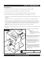
Flame Adjustment - Visual
Flame is over-fired (Fig. 20).
• Dark yellow, to orange in color.
• The flame is hitting the walls, filling the chamber with a smokey
flame. Correct immediately or chamber may be damaged.
• Decrease fuel pressure, and adjust combustion air baffle. Air pressure
may also need to be adjusted.
Problem: Too large of a flame, dark yellow in color.
1. Too much fuel pressure.
2. Not enough combustion air.
3. Not enough atomizing air pressure.
4. Ash inside the chamber is dark brown to sooty black in color.
Figure 20
BAD FLAME
The flame is too big, creating an over-fire
condition
Flame is under-fired (Fig. 21).
• The flame is like a blow torch.
• Light yellow, to white in color.
• Flame is too short.
• Check to see if pre-heater block is hot.
• Check air PSI, it may be too high. Adjust in 1 LB. increments.
• Oil pressure and the combustion air baffle may need adjustment.
Problem: Too small a flame, similar to a blowtorch.
1. Too much atomizing air pressure.
2. Too much combustion air pressure.
3. Not enough fuel pressure.
Figure 21
BAD FLAME
The flame is too short
Solutions:
1. Correct fuel pressure setting.
2. Flame tips reach 3/4 of the way into the chamber.
3. Flame has slightly yellow/orange tips.
4. No black smoke coming from the chimney.
5. Ash inside the chamber is white to off white in color.
Flame is full (Fig. 22).
• Bright yellow in color.
• Flame extends 3/4 into the chamber.
• Flame is not impinging on the chamber walls.
If you need assistance with flame adjustment, please call Lanair's
Parts and Service Department.
!
!
30
Figure 22
GOOD FLAME
The flame length is approximately 3/4 of
the chamber
DO NOT OVER FIRE YOUR BOILER. IMMEDIATELY ADJUST THE BURNER TO THE PROPER
FLAME LENGTH TO PREVENT DAMAGE TO YOUR BOILER.
CHECK FLAME DAILY (see page 31). ADJUST ACCORDINGLY
QUESTIONS?... Contact Customer Service at 1-888-370-6531 M-F 8:00 am- 4:15 pm CST
3ECTION3ERVICE-AINTENANCE
-83%2)%3 "/),%23%26)#%-!).4%.!.#% 3#(%$5,%
$!),9
7%%+,9
-/.4(,9
!..5!,,9
3EASON3HUT$OWN
s #HECKFUELSUPPLYTANK
LEVEL
s #HECKVACUUMGAUGE
READINGONSUCTIONLINE
3EE3ECTION
s $RAINWATERANTIFREEZE
FROMTHEFUELSUPPLY
TANK
s #HECKTHECOMBUSTION
CHAMBERFLUEPASSAGES
#LEANIFNEEDEDSEE
PAGE
s 3HUTOFFMAINPOWERSUP
PLYTOBOILER
s 0ERFORMMONTHLYSERV
s #HECKTHEAIRPRESSURE
ICEMAINTENANCE
SETTINGONTHEPRIMARYAIR s #LEANTHECHIMNEY CHIM
REGULATOR 3ETTOPSI
NEYCONNECTORANDBARO s &LIPAIRFUELPREHEATER
s #HECKATOMIZINGAIRPRES
METRICDAMPER
SWITCHOFF
SUREATTHEAIRFILTERREGU s $RAINWATERFROMTHEAIR
LATOR 3ETTOPSI $RAIN
PRESSURESUPPLYLINE
s #LEANPUMPSTRAINER SUC s 3HUTOFFAIRSUPPLY
WATERFROMTHEBOWLIF
DRAINLEGANDPRIMARY
TIONLINESTRAINERAND
NECESSARY
REGULATOR
PICKUPTUBESTRAINERPP s 2EMOVEAIRFUELPRE
./4% !LWAYSPRIME
HEATERASSEMBLY
s #HECKTHEFUELPRESSURE
PUMPAFTERCLEANING
$ISASSEMBLEANDCLEAN
GAUGEONTHEBURNER SET
STRAINERS
2EPLACEALLORINGSPP
TOTHECORRECTPRESSURE
FORTHEFUELBEINGUSED
s #HECKFORDIRTBUILDUP
ONTHECOMBUSTION
s 2EMOVEAIRTURBULATOR
s 6ISUALLYINSPECTFLAME
BLOWERWHEEL +EEP
ANDCLEANPP !DJUSTACCORDINGLY
WHEELCLEAN
s 2EPLACENOZZLEANDQUAD
s #HECKDRAFTUSINGA
s )NSPECTTHECOMBUSTION
RINGPP MANOMETER 3ETDRAFTTO
CHAMBER ASHBUILDUP
COLD HOT
ANDFLAME
s 2EPLACE)GNITORPP
s )FBOILERISNOTTOBEUSED
FORANEXTENDEDPERIOD
OFTIME FLIPTHEPRE
HEATERROCKERSWITCHOFF
LIGHTOFF s !DJUSTTURBULATORPP
s ,UBRICATEALLMOTORSFOL
LOWINGSPECIFICATIONSON
THEMOTORRATINGPLATE
s #LEANFUELPUMP
STRAINERSEEPP
s $RAINANDCLEANFUELSUP
PLYTANK
s #LEANCOMBUSTIONBLOW
ER
!
./4% !,7!937%!2%9% &!#%!.$ "2%!4().'02/4%#4)/.!.$02/4%#4)6%#,/4(
).'7(%.).30%#4).'/2#,%!.).'#(!-"%2/2!$*534).'&,!-%
6ISITOURWEBSITEAT WWWLANAIRCOM
3ECTION3ERVICE-AINTENANCE
!
!
./4% !,7!937%!2%9% &!#%!.$"2%!4().'02/4%#4)/.!.$02/4%#4)6%#,/4(
).'7(%.).30%#4).'/2#,%!.).'#(!-"%2
7!2.).' $)3#/..%#4!,,%,%#42)#!,0/7%24/"/),%2"%&/2%3%26)#).'
&LUE#OMBUSTION#HAMBER#LEANING
4HEBOILERCOREMUSTBECOMPLETELYCOOLTOTHETOUCHBEFOREATTEMPTINGTOCLEAN
4URNOFFALLPOWERTOTHEBOILER6!#ATTHEMAINDISCONNECT
4URNOFFAIRPRESSURESUPPLY
$ISCONNECTPOWERLINEFROMBURNER1UICK$ISCONNECTCABLEFROMSERVICEBOXTOBURNER
$ISCONNECTAIRLINEFROMBURNER
2EMOVEBOLTSFROMTHEBOILERDOOR #AREFULLYSWINGTHEBOILERDOOROPEN
2EMOVESMOKEPIPEANDCLEANOUTPORTCOVERSATREAROFTHEBOILER
5SINGACLEANINGBRUSH SCRUBALLFIRESIDESURFACESINCOMBUSTIONCHAMBER FLUEPASSAGESANDFLUECOLLECTORAREAS
5SEANINDUSTRIALTYPECANISTERVACUUMCLEANERWITHAHIGHEFFICIENCYFILTERTOREMOVEANYASHFROMTHECHAMBEROR
FLUEPASSAGES &AILURETOCLEANFLUEPASSAGESWILLIMPAIRDRAFT
)NSPECTTHECOMBUSTIONCHAMBERANDFLUEPASSAGES
2ECONNECTSMOKEPIPEANDREINSTALLCLEANOUTPORTCOVERSATREAROFTHEBOILER ./4% $ONOTOVERTIGHTENBOLTSOF
THECLEANOUTPORTCOVERS /VERTIGHTENINGMAYCRACKORBREAKTHECOVERS
#HECKTHEFRONTDOORANDFLUECOLLECTORROPESEALS 2EPLACEASREQUIRED
2EASSEMBLEBOILERDOORANDBURNERCONNECTIONS
)-0/24!.4 7HENBOILERISTOBELAYEDUPATTHEENDOFTHEHEATINGSEASONOROUTOFSERVICEFORA
PROLONGEDPERIODOFTIME
! -AKESUREALLBOILERSURFACESARECLEANANDDRY
" /PENBOILERFRONTDOORANDPLACEATRAYOFCALCIUMCHLORIDEINTHECENTEROFTHEFURNACE 4HISWILLABSORB
MOISTUREANDKEEPTHEHEATTRANSFERSURFACESDRY 7HENCALCIUMCHLORIDEBECOMESMUSHY REPLACEWITHNEW
# "LOCKTHEDOORAPPROXIMATELYOPEN
15%34)/.3 #ONTACT#USTOMER3ERVICEAT1-888-370-6531-&AM15PM#34
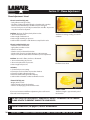
Section 18 - Service / Maintenance
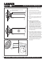
Cleaning Suction Line Strainer
bolt
The suction line strainer should be cleaned every 30
days of operation. The element is a washable metal
element. If your waste oil is extremely dirty, this strainer
may need to be cleaned more frequently. Your vacuum
gauge will help you determine when the filter needs
cleaning. The vacuum gauge reading should not exceed
5" HG of vacuum. If it does, the strainer needs cleaning.
washer
o-ring
outlet 1” NPT
1. Disconnect power to the boiler.
2. While holding the lower housing, unscrew the center bolt on the top of the suction line strainer.
inlet 1” NPT
3. Rinse the filter and lower housing in solvent.
strainer
4. Air dry the strainer and lower housing.
5. Re-assemble the strainer, ensuring the rubber gaskets, spring and o-rings are in place.
gasket
6. Fill the lower housing with waste oil or fuel oil.
o-ring
spring
bowl
7. Position the lower housing to the top making sure
the o-ring is properly seated. Secure the top and
bottom together using the bolt, washer and gasket removed earlier.
8. Prime the fuel pump (see page 28).
Cleaning/Replacing Fuel Pump Strainer
water drain
1. Disconnect power to the boiler.
2. Remove four hex head screws from pump cover.
Carefully remove cover, strainer and gasket.
3. Clean housing, strainer and pump surface. Check
for excess wear.
strainer
4. Install a new gasket (P/N 9817).
gasket
5. Install strainer and pump housing.
6. Prime the fuel pump (see page 28).
hex cap screws
Visit our website at: www.lanair.com
33
2EF
.O
0ART
.O
1TY
$ESCRIPTION
TURBULATOR
SETSCREW
NOZZLE"OILER-8"
NOZZLE"OILER-8"
QUADRING+
AIRPREHEATERBLOCK
IGNITORASSEMBLY
HEXCAPSCREW
FLATWASHER
CONNECTOR
ORING
ORING
AIRCARTRIDGEHEATER
SP R I N G 6ITONINSERT
PLUNGER
!DAPTERBLOCKASSEMBLY
HEXHEADCAPSCREW
ORING+
DIAPHRAGMASSEMBLY
HEXHEADCAPSCREW
OILPREHEATERBLOCK
)NJECTER0IN
CONTAINEDINTUNEUPKIT
CONTAINEDINTUNEUPKIT
3EEPAGESFORREQUIRED
ANNUALOILBLOCKMAINTENANCE
3ECTION3ERVICE-AINTENANCE
!NNUAL-AINTENANCE!IR0RE(EATER
!IR0RE(EATER4UNE5P
+ITS0.2EQUIRED
15%34)/.3 #ONTACT#USTOMER3ERVICEAT-&AM15PM#34
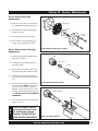
Section 18 - Service / Maintenance
1. Remove Pre-Heater Assembly
• Disconnect the air line from the brass fitting on the air pre-heater and then from
the air solenoid and remove.
• Disconnect wiring from the oil pre-heater cartridge, air pre-heater cartridge and
snap disc assembly in the wiring junction box.
• Disconnect fuel line and fitting (6) from the oil block (5).
• Disconnect fuel pressure gauge (8) and fitting from the oil block (5).
• Remove button hex screw (14) and washer (11).
• Lift pre-heater assembly and carefully pull straight back. Remove entire assembly
from the burner.
• Remove ignitor assembly (6).
2. Remove Diaphragm Assembly from Air Pre-Heater
• Carefully place pre-heater assembly in a vice. NOTE: Do not damage pre-heater.
• Unscrew diaphragm assembly (19) from air pre-heater and set aside. Remove o-ring
and discard.
Remove wires from the block by
inserting a flat tip screwdriver
into the top slot. Push tip all the
way down and push forward.
Remove wire.
3. Remove Adapter Assembly
• Remove hex cap screws (17) and set adapter assembly aside.
4. Remove Plunger , Spring and Cartridge Heater
• Remove spring (13) from plunger (15) and discard.
• Using a hook or screwdriver, carefully remove Viton insert (14) and discard.
• Remove and discard 1/4" o-ring (10) and 11/16" o-ring (11).
• Loosen and remove cartridge heater and set aside.
5. Remove Nozzle Assembly and Quad Ring
• Remove nozzle assembly (3) using a 9/16" wrench.
• If quad ring (4) does not come out with nozzle, carefully remove it and discard.
6. Clean all parts using a parts washer
• All passages must be thoroughly cleaned with a brush.
7. Replace Nozzle Assembly and Quad Ring
• After cleaning air pre-heater assembly, blow dry.
• Install new quad ring (4). Before inserting quad ring in air pre-heater block, a light coat of oil should be
applied. NOTE: Make sure quad ring is properly seated in block before proceeding (see page 39 for clarification).
• Apply a light coat of oil to the shaft of the new nozzle assembly (3). Carefully insert new nozzle assembly (3)
through the quad ring and into the block. Hand tighten until snug.
• Check alignment of ignitors and adjust if necessary (see page 38).
8. Replace O-rings and Plunger
• Insert a new 1/4" o-ring (10) and a new 11/16" o-ring (11) into the air pre-heater block (5).
• Insert new Viton insert (14) into the end of the plunger (15) and place new spring (13) on the end of the
plunger. Insert plunger into air pre-heater block spring end first.
9. Replace Cartridge Heater
•
Apply pipe dope to cartridge heater threads. Insert cartridge heater into air pre-heater block and tighten.
10. Replace Adapter Assembly
• Align the holes of the adapter assembly (16) with those on the air pre-heater block (5). NOTE: Make
sure the small end of the adapter pin is facing toward the air pre-heater block.
• Attach the Adapter assembly (16) to the block using two hex cap screws (17). Tighten screws.
11. Replace Diaphragm
• Replace diaphragm, o-ring and spring (see page 39) Re-attach diaphragm assembly and hand tighten.
NOTE: Do not over tighten.
12. Replace Ignitor Assembly (see page 39)
13. Service Oil Pre-Heater (see pages 36-37 for Annual Maintenance Instructions)
Visit our website at: www.lanair.com
35
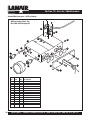
Section 18 - Service / Maintenance
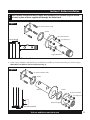
Annual Maintenance - Oil Pre-Heater
Oil Pre-Heater Tune -Up
Kit (PN# 9869) Required.
13
12
12
10
12
5
9
4
7
11
6
14
7
6
1
2
8
3
Ref.
No.
1
2
3
4
5
6
7
8
9
10
11
12
13
14
Part
No.
8992
9813
9869
9869
2901
9029
9869
8499
7242
9869
7418
7109
9366
7242
Qty.
1
1
6
4
1
2
2
1
1
1
1
3
1
1
Description
cartridge heater
pre-heater face plate
hex cap screw *
o-ring 13/16" OD *
oil block
fitting
o-ring 5/16" OD *
oil gauge
hex cap screw
o-ring 1/2" OD *
washer
plug
snap disc assembly
button hex screw
* contained in tune up kit 9869
36
QUESTIONS?... Contact Customer Service at 1-888-370-6531 M-F 8:00 am- 4:15 pm CST
Section 18 - Service / Maintenance
1. Separate Air Pre-Heater from Oil Pre-Heater
• Remove o-ring and discard(10).
2. Disassemble Oil Pre-Heater
• Remove o-ring and discard(10).
• Remove six hex cap screws (3) from face plate (2) and discard.
• Remove oil cartridge heater (1).
• Remove four 13/16"OD o-rings and discard(4).
• Remove three plugs (12) from oil block (5)
• Remove hex cap screw (9) from inside oil pre-heater block and clean. NOTE: Do not discard (5).
3. Clean Oil Pre-Heater Block
• Clean oil pre-heater block using a parts washer and brush. NOTE: Make sure all passages are clean.
• Blow dry the oil pre-heater block. inspect ALL passages making sure they are clear and clean.
4. Reassemble Oil Pre-Heater
• Replace four 13/16" OD o-rings (4) with new.
• Replace cartridge heater. NOTE: Do not over-tighten.
• Re-attach face plate (2) using six new hex cap screws (3) provided with tune-up kit (P/N 7240).
• Apply loc-tite to three block plugs (12) and replace.
• Replace hex cap screw (9) inside oil pre-heater block (5).
• Replace o-ring (10) with new.
5. Attach Air Pre-Heater Assembly
• Align the holes of the ignitor assembly and air pre-heater with those of the oil pre-heater (see page 34).
• Attach air pre-heater assembly to the oil pre-heater block (5) using two hex cap screws. Tighten securely.
6. Re-install Pre-Heater Assembly
• Place the air/oil pre-heater assembly into the burner body.
• Align the holes of the pre-heater assembly with those in the burner body.
• Secure the assembly to the body by re-installing the button hex screw (14) and washer (11). NOTE:Do not tighten
this screw at this time.
• Replace the o-rings (7) on the PSI gauge and the oil line fittings (6) with new. NOTE:Do not tighten these fittings at
this time.
• Adjust the pre-heater assembly for proper setting. The end of the turbulator should be recessed approximately 1/4"
into the burner tube (see page 38 for turbulator adjustment).
• Once adjusted tighten button hex screw (14) and fittings (6)securely.
7. Re-connect Electrical
• Re-connect all wires previously disconnected in the electrical junction box (refer to wiring diagram, page 23 and
the burner reference diagram, page 43).
8. Reconnect PSI Gauge, Fuel Line and Air Line
• Reconnect the PSI gauge (8) to the fitting (6) and tighten securely.
• Reconnect the fuel line to the fitting (6) and tighten securely.
• Reconnect the air line by connecting the one end of the air line to the air solenoid and the other end to the
air fitting (see page 34).
9. Test Operation
• Follow start-up procedure, page 26.
Visit our website at: www.lanair.com
37
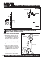
Section 18 - Service / Maintenance
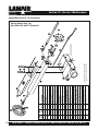
Ignitor Replacement / Adjustment
electrodes should extend approximately
1/8” beyond nozzle tip
1. Disconnect power to the boiler.
2. Remove the pre-heater assembly from
the burner housing. Disassemble and
clean all parts as instructed on pages
34-37.
3/8”
3. Using a 7/16" wrench, carefully remove
the one-piece ignitor from the air preheater.
1/16”
Side View
4. Install a new one piece ignitor
(P/N 3730) to the top of the air preheater. NOTE: The tips of the ignitor
should be 3/8" above the center of the
nozzle assembly and should extend
approximately 1/8" beyond the end of
the nozzle. The tips of the one piece
ignitor should be 1/8" apart. Adjust as
required and tighten nut on the top of
the ignitor (see illustrations for clarification of placement).
1/8”
5. Re-assemble pre-heater assembly (see
pages 34-37) carefully re-install the preheater assembly into burner housing.
The turbulator should be approximately
1/4” from the end of the burner tube.
Adjust as required and secure the preheater assembly to the burner housing
by tightening the adjustment screw on
the side of the burner housing (see
illustration).
Top View
Pre-heater Assembly
adjustment screw
Turbulator 1/4” max. from
end of the tube
38
QUESTIONS?... Contact Customer Service at 1-888-370-6531 M-F 8:00 am- 4:15 pm CST
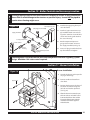
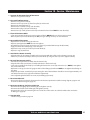
Section 18 - Service / Maintenance
Air Pre-Heater Diaphragm
Replacement
o-ring
diaphragm
1. Remove the four hex cap screws from
the diaphragm assembly and discard.
piston
2. Disassemble and discard diaphragm,
spring and o-ring .
hex cap
screws
3. Thoroughly clean remaining parts.
spring
4. Re-assemble using new diaphragm,
o-ring, spring and hex cap screws.
Air Pre-Heater Nozzle Cleaning /
Replacement
1. Periodic cleaning of the nozzle assembly may be required.
2. Carefully remove nozzle from the air
pre-heater block.
Air Pre-Heater Diaphragm Assembly
body
fuel orifice
pin/seat
3. Disassemble the nozzle as shown and
clean thoroughly. Re-assemble nozzle.
4. Carefully remove the quad ring from
the block and inspect. Replace if necessary.
5. Insert clean/new quad ring into the air
pre-heater block. NOTE: The quad ring
must be properly seated. Failure to
properly seat the quad ring may result
in leakage and improper burner operation. DO NOT INSTALL QUAD RING ON
THE NOZZLE.
Air Pre-Heater Nozzle Assembly
nozzle assembly
quad ring
6. Lubricate pin/seat and re-install nozzle.
Tighten securely.
!
Failure to properly seat the
quad ring may result in leakage and improper burner
operation. DO NOT INSTALL
QUAD RING ON THE NOZZLE.
Proper Quad Ring Position
Visit our website at: www.lanair.com
39
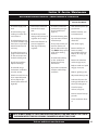
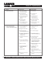
Section 19 - Troubleshooting
Symptom
Possible Cause
Corrective Action
A. Burner will not start
1. Main electrical power
circuit breaker tripped
1. Reset breaker
2. Service disconnect
switch off or fuse blown
2. Turn switch on or
replace fuse
3. Thermostat turned down/
improperly installed/
defective
3. Turn thermostat up,
check wires/test
components/replace
4. Oil primary safety
tripped/defective
4. Reset/test components,
replace if needed
5. Too much light showing
on cad cell/defective
5. Eliminate light to cad cell
Test component
1. Low oil in supply tank or
contaminated fuel
1. Fill tank, or drain and
clean tank
2. Plugged or worn nozzle
2. Clean or replace
3. Fuel pressure gauge
fluctuating/pumping system
3. See section 7, Page 12
4. Pre-heater switch is turned off
or defective, or defective
cartridge heater
4. Turn switch on or test
switch and cartridge heater
5. Transformer/electrodes not
sparking
5. Test transformer/look
for shorts & repair
Replace electrodes/ transformer
6. No air pressure/defective
regulator/defective solenoid
6. Turn compressor on/test
regulator/solenoid. Replace
defective components
7. Water in air system
7. Clean air pre-heater and drain
water from system
8. Combustion blower not
properly adjusted or
defective
8. See flame adjustment
pages 29-30.
Replace blower
9. Improper draft
9. Check draft see page 11.
Make sure chimney is properly
installed
10. Plugged heat exchanger,
or chimney
10. Clean heater including manifold,
chimney
B. Burner attempts to fire,
but does not establish a flame
40
QUESTIONS?... Contact Customer Service at 1-888-370-6531 M-F 8:00 am- 4:15 pm CST
3ECTION4ROUBLE3HOOTING
3YMPTOM
0OSSIBLE#AUSE
#ORRECTIVE!CTION
# "URNERFIRES ANDTHEN
FAILSONOILPRIMARYSAFETY
#ONTAMINATEDFUELSUPPLY
WATERANTIFREEZEGEARLUBE
ORDIRTYFUELFILTER
$RAINANDCLEANFUEL
SUPPLYTANK #LEANFUEL
FILTERSEEPAGE
)MPROPERDRAFT
#HECKDRAFTSEEPAGE
-AKESURECHIMNEYISPROPERLY
INSTALLED
0LUGGEDHEATEXCHANGER
MANIFOLD ORCHIMNEY
#LEANHEATERINCLUDINGMANIFOLD
ANDCHIMNEY
7RONGAIRPRESSURE
3EEFLAMEADJUSTMENTPAGES
7RONGFUELPRESSUREOR
PRESSUREFLUCTUATING
3EEFLAMEADJUSTMENT
PAGES 3EEFUELPIPING
PAGE
)MPROPERCOMBUSTIONBLOWER
SETTING ORBLOWERISDEFECTIVE
3EEFLAMEADJUSTMENT
PAGES 3EEFUELPIPING
PAGE
/ILPRIMARYCADCELLDEFECTIVE
#ADCELLIMPROPERLYADJUSTED
$IRTYFLAMETURBULATOR
4ESTCOMPONENTSADJUST
CADCELLCLEANTURBULATOR
0LUGGEDNOZZLEORPREHEATER
ASSEMBLY
#LEANNOZZLEANDORPREHEATER
ASSEMBLY
#ARTRIDGEHEATERSDEFECTIVE
ORDISCONNECTED
4ESTCARTRIDGEHEATERSAT
ROOMTEMPERATUREUSING
ANOHMMETER
!IRHEATER7 ¼
/ILHEATER7 ¼
$ 0REHEATERASSEMBLY
NOTHEATING
3NAPDISCDEFECTIVE
(I,IMITSNAPDISCDEFECTIVE
4ESTSNAPSWITCHFORCONTINUITYIF
PREHEATERISCOLD
2EPLACESNAPDISCASSEMBLY
6ISITOURWEBSITEAT WWWLANAIRCOM
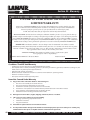
3ECTION7ARRANTY
LANAIR 1O YEAR WASTE OIL BOILER
LIMITED WARRANTY
Lenan Corp., MANUFACTURER, hereby warrants that manufacturer’s products shall be free from
defect in material and workmanship under normal use according to the provisions and limitations
herein set forth for a period of one (1) year provided same is returned (pre-paid)
F.O.B. Janesville, Wisconsin for inspection and warranty determination.
MANUFACTURER warrants the heat exchanger/combustion chamber for three (3) years from the date of
purchase and pro rata thereafter according to the following schedule: If a defect occurs during the first three
years, MANUFACTURER will repair or replace the combustion chamber / heat exchanger FREE* of charge.
If a defect occurs in years four through ten (4-10) MANUFACTURER will repair or replace your combustion
chamber/heat exchanger. Your guaranteed replacement cost will be shared by MANUFACTURER 50/50.
IMPORTANT: Combustion chamber / heat exchanger must be maintained in accordance with the
installation/operating instructions. This extended warranty does not cover normal wear items such as gasket
material, chamber inserts, nuts, bolts, labor costs, etc. The warranty card must be returned within ten (10)
days of purchase date in order for this warranty to be valid.
*MANUFACTURER’S determination regarding repair or replacement is final.
Cost of freight is owner’s responsibility.
Model Number MXB 250 / 400 Series Boiler
Date Purchased:
#ONDITIONS4HAT7ILL6OID7ARRANTY
s )NSTALLATIONBYANYONEOTHERTHANALICENSED(6!#(YDRONICS)NSTALLER
s 5SEOFLIQUIDSSUCHAS SOLVENTS BRAKEFLUID GASOLINE + KEROSENE PAINTTHINNERS GEARLUBE TRANSFORMEROIL CUTTINGOILS ANTI
FREEZE WATERORANYOTHERLIQUIDNOTAPPROVEDFORUSE
s 4AMPERINGWITHINTERNALCOMPONENTS
s "OILERHASNOTBEENINSTALLEDORSERVICEDINACCORDANCETOTHEINSTALLATIONOPERATINGMANUAL
s !LTERATIONORMISUSEOFANYPART
s 5SEOFPARTSOTHERTHANTHOSESUPPLIEDBY,ANAIR
)TEMS.OT#OVERED5NDER7ARRANTY
!
!NYPORTIONOFTHECOMBUSTIONCHAMBERHEATEXCHANGERIF
4HEUNITISNOTINSTALLEDPERTHEOWNERSMANUAL
4HEYEARLYINSPECTIONREQUIREMENTSARENOTCURRENT
)FTHEBOILERISUSEDFORAPURPOSEFORWHICHITISNOTINTENDED
)FTHEBOILERISNOTOPERATEDINACCORDANCEWITHTHEPRINTEDINSTRUCTIONSINTHEOWNERSMANUAL
)FANYALTERATIONSORUNAUTHORIZEDREPAIRSAREMADETOTHEUNIT
-AINTENENCEITEMSINCLUDINGNORMALWEARTEARITEMS
"
$AMAGEINCURREDFROMABUSE NEGLECT SHIPPING NATURALACTS MISUSEORACCIDENT
#
,ABORCOSTSFORSERVICECALLSFORANYREASONINCLUDING
#LEANINGORPERFORMINGREQUIREDMAINTENANCE
)NSTALLATIONCORRECTIONS
!NYPARTSINSTALLATION
$
0ARTSTHATAREREPLACEDBECAUSEOFNORMALWEARANDTEAR
%
'OODSPURCHASEDUNDERTHISAGREEMENTSHALLBEUSEDEXCLUSIVELYBYTHEBUYERANDNOOTHERPERSONORTHIRDPARTY
SHALLBENEFITFROMTHEEXPRESSORIMPLIEDWARRANTIESCONTAINEDINTHEAGREEMENT
15%34)/.3 #ONTACT#USTOMER3ERVICEAT-&M#34
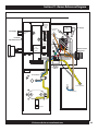
3ECTION"URNER2EFERENCE$IAGRAM
Ignitor
Manual
Reset &
Snap
Disk
Fuel Supply
Oil
Pre-Heater
Block
Air
Solenoid
To Combustion
Blower
Air Supply
Pre-Heater
Adjustment Screw
Air
Supply
Air
Pre-Heater
Block
Electrical Quick
Disconnect
Oil Pressure
Gauge
Pre-Heater
Switch
View Port
To Transformer
To “F” Terminals
To Oil Primary
Cad Cell
Cover
Burner Cover
6ISITOURWEBSITEAT WWWLANAIRCOM
¸
,ANAIR7ASTE/IL(EATERS"OILERS
#APITAL#IRCLE
*ANESVILLE 7ISCONSIN
WWWLANAIRCOM
© 2004 Martrade LLC
Lanair is a registered trademark of Martrade LLC
P/N 5051