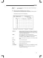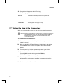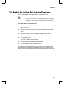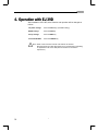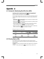
1
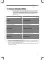
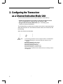
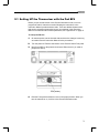
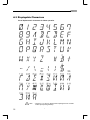
VHF FM MOBILE TRANSCEIVER Dealer’s Manual Alinco’s DR-135 transceivers support the Channel Indication mode (User’s mode), which protects dealer-defined parameter settings from being changed by the user. This manual describes the functions available in the Channel Indication mode and the procedures for configuring the transceiver. It also covers the instructions for installing and using the DR-135 Channel Data Editor software. For information about programming manually, see the instruction manual provided with the product. Contents 1 Channel Indication Mode ・・・・・・・・・・・・・・・・・・・・・・・・・・・・・・・・・・・ 1 2 Configuring the Transceiver as a Channel-Indication-Mode Unit ・・ 2 2.1 2.2 2.3 Setting UP the Transceiver with the Pad BP4・・・・・・・・・・・・・・・・・・・・・ 3 Setting Up the Transceiver with the CH Data Editor ・・・・・・・・・・・・・・・ 4 Setting UP the Transceiver with the EJ-39D trunking logic board. ・・・ 5 3 DR-135 Channel Data Editor ・・・・・・・・・・・・・・・・・・・・・・・・・・・・・・・・ 6 3.1 3.2 3.3 3.4 3.5 3.6 3.7 3.8 Installing the Data Editor ・・・・・・・・・・・・・・・・・・・・・・・・・・・・・・・・・・・・・・ 6 Starting the Data Editor ・・・・・・・・・・・・・・・・・・・・・・・・・・・・・・・・・・・・・・・ 6 Setting the Channel Data (Main Menu) ・・・・・・・・・・・・・・・・・・・・・・・・・・ 7 Changing the Transceiver Settings・・・・・・・・・・・・・・・・・・・・・・・・・・・・・・ 9 Setting Auto DiaIer Memories ・・・・・・・・・・・・・・・・・・・・・・・・・・・・・・・・・ 10 Starting the Data Editor for the EJ-39D (Trunking Mode) ・・・・・・・・・・ 10 Writing the Data in the Transceiver・・・・・・・・・・・・・・・・・・・・・・・・・・・・・・11 Reading the Existing Data from the Transceiver ・・・・・・・・・・・・・・・・・ 13 4 Operation with EJ-39D・・・・・・・・・・・・・・・・・・・・・・・・・・・・・・・・・・・・・ 14 Appendix A ・・・・・・・・・・・・・・・・・・・・・・・・・・・・・・・・・・・・・・・・・・・・・・・・ 15 A.1 Automatic Numbering Identification (ANI) ・・・・・・・・・・・・・・・・・・・・・ 15 A.2 A.3 Priority Watch (PRI)・・・・・・・・・・・・・・・・・・・・・・・・・・・・・・・・・・・・・・・・・・ 15 Displayable Characters ・・・・・・・・・・・・・・・・・・・・・・・・・・・・・・・・・・・・・・ 16 *Names of products mentioned in this manual are used for identification purposes only and may be trademark and/or registered trademarks of their respective company. 1. Channel Indication Mode When the transceiver is in the Channel Indication mode, some functions are completely disabled, some are programmable only with the Channel Data Editor software (not programmable with the transceiver switches), and others are left available. The following table lists the functions provided with the DR135 transceiver. Those marked with“◎”remains active in the Channel Indication mode. Naming channel memories *1 Installed EJ-39D *1 Cloning ◎ ◎ Set mode Tone burst transmission *2 Changing VFO frequency Resetting CPU Transmission ◎ Monitor *2 Scanning memories Installed EJ-39D ◎ *2 Calling up a call channel Programming ANI *1 *1 Setting scanning mode *1 *1 Setting beep sound *1 *1 Auto dialer ◎ Volume level control ◎ ◎ Programming BCLO *1 *1 Adjusting squelch ◎ ◎ Programming TOT *1 *1 Programming TOT penalty *1 *1 Setting tuning step Setting frequency and offset *1 *1 Setting APO *1 *1 Setting tone squelch(CTCSS) *2 *1 Setting tone burst frequency *1 *1 Setting digital code squelch(DCS) *2 *1 Setting DTMF wait time *1 *1 Setting output power *2 *2 Setting DTMF pause/burst time *1 *1 programming auto dialer memories ◎ *1 Setting DTMF first burst time *1 *1 Programming memory channels *1 *1 Setting theft alarm *1 *1 Setting key-lock *2 *1 Setting Lamp mode *1 Setting memories skip channels *1 *1 Power supply voltage display function ◎ *1 : This function is programmable with the CH Data Editor software (not programmable with the transceiver switches) and disabled by default. *2 : This function is programmable with the CH Data Editor software (programmable with the transceiver switches) and disabled by default. (The CH Data Editor software can be used to make it possible to operate this function using the transceiver switches.) “ 1 2. Configuring the Transceiver as a Channel-Indication-Mode Unit You can set the transceiver in the Channel Indication mode either by: • Setting the pad (BP4) on the printed circuit board of the transceiver (see “2.1 Setting Up the Transceiver with the Pad BP4”); OR • Using the DR-135 Channel Data Editor (see “2.2 Setting Up the Transceiver with the Data Editor”). The CH Data Editor is useful when you want to set up two or more transceivers. When the transceiver is in the Channel Indication mode, the LCD will look like the following: When the Channel contains data: Note: 2 • The following parameters can be configured with the CH Data Editor: Enabling/Disabling the SCAN start when the channel is to be skipped. Enabling/Disabling power change Enabling/Disabling the key-lock Enabling/Disabling MONI key Enabling/Disabling CTCSS/DCS key Enabling/Disabling Tone Burst output • When the above operations are enabled and set, the setting contents are displayed. “ 2.1 Setting UP the Transceiver with the Pad BP4 Before you put the transceiver in the Channel Indication mode, be sure to program the radio’s channel memories following the instructions in the Instruction Manual provided with the radio. There are additional parameters that can be programmed manually but are not explained in the Instruction Manual: for information about these parameters, see “Appendix A” on page 15. To set up the DR-135 1. On the transceiver, set the channel data and store the changes in memory, as needed. See the Instruction Manual for the procedures. 2. Turn the power off. Remove the bottom cover. Remove Sheet Front panel. 3. Identify pad BP4 on the printed circuit board. Short-circuit it (or solder a jumper wire with it). BP4 (solder) 4. Refit the Front panel and bottom cover in the proper position. When you turn the transceiver on, it will be in the Channel Indication mode. “ 3 2.2 Setting Up the Transceiver with the CH Data Editor This section describes how to configure the transceiver as a Data-Indicationmode unit with the CH Data Editor software. The function of “Appendix A” (on page 15) can be programmed only through CH Data Editor software. To set up the transceiver with the CH Data Editor: 1. Connect the COM port (Dsub connector) on your computer to the external speaker jack on the transceiver with the ERW-4 or ERW-4C interface cable. DR-135 (Front panel) DATA terminal Computer ERW-4 or ERW-4C interface cable 2. 4 Start the Channel Data Editor on your computer. On the main menu, press the F3 key, and select the “Radio Option (R)” option. In the “Edit option data” window, select the “Channel” option in the “Indication Mode” field. Write your changes in the transceiver memory. The transceiver will then enter the Channel Indication mode. For more information about using the software, see chapter 3 “DR-135 Channel Data Editor”. “ 2.3 Setting UP the Transceiver with the EJ-39D trunking logic board. 1. Turn the transceiver off. 2. Remove the bottom cover. Connect the EJ-39D to CN101 on the DR-135 circuit board. 3. Refit the bottom cover in the proper position. EJ-39D CN101 “ 5 3. DR-135 Channel Data Editor The DR-135 Channel Data Editor is used to edit data, which includes the operation parameters for the transceiver and the settings for each channel. This software is useful when you wish to program two or more transceivers in similar ways; You can read the existing data from a master transceiver, edit the parameters on the editor, and enter the changes in other transceivers. 3.1 Installing the Data Editor The DR135 Data Editor floppy disk provided by Alinco includes data editor system files, DR135.EXE and DR135.HLP. To install the editor, the following items are required in addition to this floppy disk: • An IBM PC/AT or compatible computer is required. • PC-DOS or MS-DOS 6.2 or later version is recommended. • The Alinco ERW-4 or ERW-4C interface cable. This cable is specially designed to connect the computer to the transceiver. Do not use it for other purposes. Note: • If you run the editor with TSR software that runs off the CPU at regular intervals, or from the DOS box of Windows, or with a device driver that inhibits interruption for a long period of time, an error may occur during data transfer between the PC and radio. To instalI the editor: 1. Make an new directory for the data editor system, if needed. 2. Copy the DR135.EXE and DR135.HLP files from the DR-135 Data Editor disk to the appropriate directory. 3.2 Starting the Data Editor The Data Editor can start the DR-135 editor. Note: • If you are going to write new data into the transceiver after editing, connect the COM port (Dsub connector) on your PC to the DATA terminal on the transceiver with the interface cable (ERW-4 or ERW4C) before turning the computer on. To start the editor: 6 1. Start the DOS on your computer. 2. Go to the directory where the Data Editor is located. “ 3. To start the DR-135 Data Editor, at the DOS prompt, type: DR135.EXE or, DR135 The main menu will appear. Note: • To exit the Data Editor, press the F2 key, select the “Quite Editor (Q)” option, and type Y. 3.3 Setting the Channel Data (Main Menu) On the main menu, you can set the parameters for each channel. To move the cursor between the fields, use the cursor keys. To select an option in each field, press the space bar. To enter a numeric value, use the numeric keys. A detailed description of the fieIds are listed on the next page. Note: • This software supports the context-sensitive help. Press the F1 key to obtain the information about the field where the cursor is placed. Ch: Select the desired channel (from 0 through 99), PL, PH, CALL(C), and VFO(V) by using the up or down cursor keys. Name: Write an alphanumeric name instead of the CH No. Press the Enter key to go to input mode. Input the name using the keyboard, and press the Enter key to set the name. Ref: Set the channel step for the frequency to be set using CH Data Editor. “ 7 Rx Freq: Set the reception frequency. CTCSS / DCS: Set the CTCSS/DCS decoder frequency. Use the Space key to select CTCSS/DCS-off. Press the Enter key from the selected mode to open the “CTCSS tone or DCS code selection screen”. W/N: Set the operating mode (Wide/Narrow). DGT: Set the packet or APRS operation on or off. DCS DET: Set the DCS decoder detect operation on or off. Only set this to “ON” when the DCS decoder is operating incorrectly. SCN SKP: Turn the scan skip on or off. PRI: Turn the priority scan on or off. When turning it on (“VFO” appears), you can select the priority channel. Press the Enter key to open the “Select ch” box, highlight the priority channel from the list by using the cursor, Page Up, and Page Down keys, and press the Enter key to seIect it. The “Select ch” box lists only the active channel numbers. For example, suppose the transceiver is on channel 20 and channel 30 has priority. The transceiver then repeats the receiving operations for five seconds on channel 20 and for 0.5 second on channel 30. 8 Tx Freq: Set the transmission frequency. If you have read channel data including the frequency shift value from a transceiver, this area shows the appropriate transmission frequency. CTSS / DCS: Set the CTCSS/DCS encoder frequency. Use the Space key to select CTCSS/DCS-off. Press the Enter key from the selected mode to open the “CTCSS tone or DCS code selection screen”. BCLO: Turn the BCLO (Busy Channel Lock Out) on or off. ANI: Use this field to enable or disable the ANI (Automatic Numbering Identification) functions. Usually, set this field to “OFF”. “ 3.4 Changing the Transceiver Settings You can also set the transceiver parameters to stay on throughout the transceiver operation regardless of the channel currently selected. 1) On the main menu, press the F3 key, 2) select the “Radio Option (R)” option and press the Enter key to open the “Edit option data” window, 3) set the operation parameters in the window (a detailed description of the fields follows this procedure), 4) when you complete your settings, press the F4 key to close the window. The “Edit option data” window contains the items listed below. You can change options in each field by pressing the space bar. Indication Mode: Toggle between Frequency-indication mode and Channelindication mode. VFO/MR/CALL: Select the initial display mode for the set. MR No: Select the initial display channel for memory mode. SQL No: Select the initial setting value for the squelch level. Tx Power Select the output power. SCAN Start: Set whether or not SCAN operation is allowed in Channelindication mode. Tx Power Change: Set whether or not it is possible to change the TX Power in Channel-indication mode. Key Lock Change: Set whether or not Key-lock operation is possible in Channelindication mode. Moni key: Set whether or not Monitor operation is possible in Channelindication mode. Ctcss/Dcs Change: Set whether or not CTCSS/DCS setting is possible in Channelindication mode. TBST Output: Set whether or not Tone Burst operation is possible in Channelindication mode. DTMF burst delay: (DWT) key is pressed to when the Set the time from when the first digit of the DTMF code is output. DTMF 1st digit: (DB) Set the burst time for the first digit of the DTMF code. DTMF TX interval: (DP) Set the duration of the DTMF tone burst. The interval between tones will be the same as the DTMF tone burst duration. TBST Freq: Select the Tone Burst frequency. “ 9 Time out timer: Turn the TOT (Time Out Timer) off, or select a transmission time by pressing the space bar. You can reverse the order of the options by holding down the Shift key and pressing the space key is key. The time out timer starts working when the pressed. When the timer expires, the transceiver will automatically shut the transmission off. Time out penalty: Turn the TOT penalty off, or select the penalty time. You can reverse the order of the options by holding down the Shift key and pressing the space key. If the timer expires during transmission, the operator cannot restart the transmission unit the time you specify in this field elapses. Key Lock: Activate the key lock or frequency lock to avoid misoperation. You can also disable Key Lock functions. APO: Turn the auto-power-off feature on or off. Beep sound: Set the beep sound ON/Off. Scanning Mode: Set SCAN mode (Timer/Busy). Lamp Mode: Set the lamp lighting mode (High or Low). Security Mode: Set the Theft Alarm function ON/Off. 3.5 Setting Auto DiaIer Memories To program the dialer memories, 1) on the main menu, press the F3 key, 2) select the “Auto Dialer (A)” option and press the Enter key to open the “Edit auto dialer” window, 3) select the desired memory number, and enter a numeric value (up to 16 digits), 4) press the Enter key, 5) when you complete your settings, press the F4 key to close the window. 3.6 Starting the Data Editor for the EJ-39D (Trunking Mode) After installing EJ-39D, the radio becomes in Trunking mode with memory BANKs. Program the memory in each BANK as follows: 1. Install the Data Editor and type as following next to DOS prompt. DR135.EXE/TRUNK or, DR135/TRUNK The main menu for trunking will appear. 10 “ Note: 2. • To exit the Data Editor, press the F2 key, select the “Quite Editor (Q)” option, and type Y. Setting the Channel Data(Main Menu)for Trunking Only following items can be programmed in Data Editor (Trunking mode). CH Data Edtor Version 1.00 Trunking Mode BANK-Ch: Select the desired channel (from 1-01 through 1-16), (from 2-01 through 2-16) (from 3-01 through 3-16), (from 4-01 through 416), (from 5-01 through 5-16) and (from C-01 through C-16) by using the up or down cursor keys. Name: Write an alphanumeric name instead of the CH No. Press the Enter key to go to input mode. Input the name using the keyboard, and press the Enter key to set the name. Ref: Set the channel step for the frequency to be set using CH Data Editor. Rx Freq: Set the reception frequency. W/N: Select the operating mode Wide/Narrow. Tx Freq: Set the reception frequency. CTCSS ENC: Set the CTCSS encoder frequency. Use the Space key to select CTCSS - off. Press the Enter key from the selected mode to open the “CTCSS tone selection screen”. “ 11 3. Changing the Editor option data for Trunking. Set followings by F3 key in main menu. SQL No: Selects the initial setting value for the squelch level. TX POWER: Select the output power. APO: Turn the auto-power-off feature on or off. LAMP Mode: Set the lighting mode (High or Low). 3.7 Writing the Data in the Transceiver When you complete editing, store the new data in the transceiver memory. Caution: • Make sure the COM port (Dsub connector) on the PC is connected to the DATA terminal on the radio with the interface cable (ERW-4 or ERW-4C). If not, turn off the computer and transceiver before connecting the cable. To write the dala in the transceiver: 12 1. On the main menu, press the F4 key. A window will open on the lowerright of the screen. 2. Make sure the “Write CH Data (W)” option is highlighted in the window. Press the Enter key to open the “Wiring the channel data into radio” window. 3. Press the space bar. Another message may appear in the window, however you can ignore it, and press the space bar again. 4. Turn the transceiver on. Press the CALL key while holding down the FUNC key. “CLONE”is displayed on the display. 5. Press the space bar to start transferring the data. The message window will open, telling you the transfer operation is completed successfully. Press the Enter key to close the window. 6. Turn the transceiver off to cancel Clone mode. “ 3.8 Reading the Existing Data from the Transceiver You can read the data currently stored in the transceiver memory. Caution: • Make sure the COM port (Dsub connector) on the PC is connected to the external speaker jack on the radio with the interface cable (ERW4 or ERW-4C). If not, turn off the computer and transceiver before connecting the cable. To read the data from the transceiver: 1. On the main menu, press the F4 key. A window will open on the lowerright of the screen. 2. Make sure the “Read CH Data (R)” option is highlighted in the window. Press the Enter key to open the “Reading the channel data from radio” window. 3. Press the space bar. Another message may appear in the window, however you can ignore it, and press the space bar again. 4. Turn the transceiver on. Press the CALL key while holding down the FUNC key. “CLONE”is displayed on the display. 5. Press the space bar to start transferring the data. 6. Turn the transceiver off to cancel Clone mode. A completion message Window will open, telling you the transfer operation was completed successfully. Press the Enter key to close the window. The data you have just obtained from the transceiver will appear in the main menu. “ 13 4. Operation with EJ-39D After Installation of EJ-39D, some function and operation will be changed as follows: TX power Change: Press the CALL key. (at Enable setting) BANK Change: Press the V/M key. Group Change: Press the MHz key. Conventional Mode: Press the TS/DCS key. Note: • Refer to the Instruction manual of EJ-39D for the function. Microphone will be muted while FUNC key is pushed when transmitting in adjustment mode of EJ-39D.(Use this function for modulation adjustment.) 14 “ Appendix.A A.1 Automatic Numbering Identification (ANI) This feature allows the transceiver to automatically send the programmed DTMF codes (up to 16 digits) just after the key is pressed and/or released so that the base station can identify the unit. Two auto dialer memories, Nos. 8 and 9, are reserved for the ANI transmission. You can enable or disable the ANI function by using the Channel Data Editor software. • When memory No. 8 contains DTMF codes, the transceiver sends the codes just after the key is pressed. • When memory No. 9 contains DTMF codes, the transceiver sends the codes just after the key is released. • When both Nos. 8 and 9 contains DTMF codes, the transceiver sends the codes immediately after the key is pressed and released. • When memory Nos. 8 and 9 are empty, the transceiver does not output any DTMF code when the key is pressed or released. Examples are given in the table below. DTMF codes in dialer memories No. 8 No. 9 8888 8888 9999 9999 DTMF codes to be sent Just after Just after is pressed is released 8888 9999 8888 9999 A.2 Priority Watch (PRI) Priority Watch monitors a channel different from the indicated frequency. Every 5 seconds, the transceiver switches from the indicated frequency to the priority channel. If a signal is received on the priority channel, the reception time is extended to 2 seconds. To stay in Priority channel, push key when Priority channel is on. “ 15 A.3 Displayable Characters List of Alphanumeric characters for Name operation Note: 16 • Display in ( ) is the P.C. Display when inputting from PC CH Data Editor. Input pushing Shift key. “ “ 17 ALINCO, INC. Head Office : “TWIN 21” MID Tower Building 25F 1-61,2-Chome, Shiromi,Chuo-ku,Osaka 540-8580,Japan Phone: 06-6946-8150 Fax: 06-6946-8175 E-mail: [email protected] U.S.A : 438 Amapola Avenue,Suite 130,Torrance,CA 90501,U.S.A Phone:310-618-8616 Fax:310-618-8758 http://www.alinco.com/ Germany : Eschborner Landstrasse 55,60489 Frankfurt am Main,Germany Phone:069-786018 Fax:069-789-60766 Dealer / Distributor © Copyright 2000 Alinco, Inc. Osaka Japan Printed in Japan PM0062 “