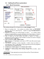
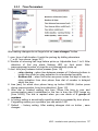
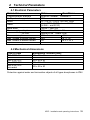
1
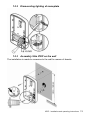
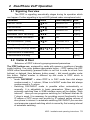
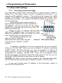
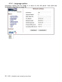
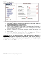
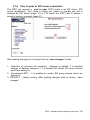
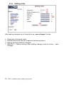
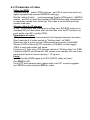
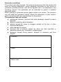
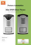
DoorPhone VoIP Slim IPDP – 01 Slim IPDP – 02 Slim IPDP – 01C Slim IPDP – 02C Slim IPDP – 01C antivandal Installation and Operating Instructions Welcome We congratulate you on purchase of “Slim IP Door phone -VoIP” (VoIP = Voice over IP). This VoIP DoorPhone provides you by many features which allows you easy communicate with visitors of company, family houses, schools, etc.. You can easily connect it to an Ethernet network or VoIP exchange or directly to SIP server through internet conection. The basic models of VoIP DoorPhone are Slim IPDP-01 ( supply with 1 button), Slim IPDP-02 ( supply with 2 buttons), Slim IPDP-01C ( supply with 1 button and camera), Slim IPDP-02C ( supply with 2 buttons and camera) and Slim IPDP-01C antivandal ( supply in stainless steel casing with 1 button and camera) . The VoIP Doorphone powering is either by AC/DC power supply 12V or by PoE (Power over Ethernet) technology. No additional cabling for power is therefore necessary. The VoIP Door phone configuration is over an integrated web server, which can be controlled from any web browser, e.g., IE, Mozilla Firefox. The manufacturer continuously improves the product firmware. The used technology allows you to upload to IPDP the latest version of the firmware any time by using a standard computer. The latest version of the firmware is available at http://www.alphatech.cz/ipdp-firmware/e_firmware.htm You will find the necessary info on page 29 of this manual. We recommend that you use the latest version of the firmware, which brings new functions and patches.. Manual version V5.9 12-8-2010 Version of firmware V1.39 and V5.8 Alphatech spol. s r.o. Jeremenkova 88 140 00 Praha 4 Tel/fax: 272103334 www.alphatech.cz / [email protected] Table of Contents 1 BASIC DESCRIPTION ....................................................................................... 5 1.1 FEATURES ...................................................................................................... 5 1.2 TERMINOLOGY ............................................................................................... 6 1.3 MODULE ASSEMBLY ...................................................................................... 7 1.4 MODULE FEATURES ....................................................................................... 7 1.4.1 Slim IPDP Basic Module ......................................................................... 7 1.5 INSTALLATION OF DOORPHONE VOIP ASSEMBLY ....................................... 12 1.5.1 Open and close the cover of Slim IPDP ................................................. 12 1.5.2 Dismounting lighting of nameplate ......................................................... 13 1.5.3 Assembly Slim IPDP on the wall............................................................. 13 1.5.4 Return lighting name plate after mounting on the wall. ......................... 14 1.5.5 Change of nameplates ............................................................................. 14 2 DOORPHONE VOIP OPERATION ............................................................... 15 2.1 SIGNALING OVERVIEW................................................................................. 15 2.2 VISITOR AT DOOR ........................................................................................ 15 2.3 PERSON INSIDE BUILDING ............................................................................ 16 2.3.1 Outgoing Call ......................................................................................... 16 2.3.2 Incoming Call ......................................................................................... 16 3 PROGRAMMING OF PARAMETERS .......................................................... 17 3.1 BASIC VOIP SETTINGS ................................................................................. 17 3.1.1 Choosing a mode and login .................................................................... 17 3.1.2 Language option ..................................................................................... 19 3.1.3 Network settings ...................................................................................... 20 3.1.4 Peer to peer or SIP server connection .................................................... 22 3.1.5 Audio codec setting ................................................................................. 24 3.1.6 Setting video............................................................................................ 25 3.1.7 Viewing the video (programme PopUp) ................................................. 26 3.1.8 Day intervals ........................................................................................... 27 3.1.9 User interface ......................................................................................... 28 3.1.10 Service settings ................................................................................... 29 3.1.11 Restart ................................................................................................ 31 3.1.12 Preparation style, language support .................................................. 32 3.2 SETTING DOORPHONE PARAMETERS ............................................................ 33 3.2.1 Basic Parameters .................................................................................... 33 3.2.2 All about relays ....................................................................................... 34 3.2.3 Time Parameters ..................................................................................... 36 3.2.4 Direct Dialing – Memories ..................................................................... 37 4 TECHNICAL PARAMETERS......................................................................... 38 4.1 ELECTRICAL PARAMETERS .......................................................................... 38 4.2 MECHANICAL DIMENSIONS .......................................................................... 38 4.3 PARAMETERS OF VIDEO ................................................................................ 39 4 IPDP - installation and operating instructions 1 Basic Description 1.1 Features Two 25digit numbers (IP adresses) under each button ( includes *, #) DAY/NIGHT switching – automatically or manually Possibility to dial * or # to prolong the communication Possibility to connect 2 independent locks ( magnetic, electrical) for door opening 5 different modes of 2 integrated relays (for example: lighting, delayed opening, etc..) 2 codes for door phone hanging up by phone 2 codes for relay activation by phone ( door opening) 6 code locks (password from buttons at the door) Adjustable number of rings before incoming call is pick up Adjustable time between button press during code dialling Adjustable time of hanging up before REDIAL Adjustable time before start dialling Power supply 12V AC/DC, 500mA max or PoE technology Integrated heating of printed circuit Permanent lighting through visiting cards White LEDs for automatic ligting for camera Integrated full color camera Ethernet – 10/100Mb with standard 10BaseT a 100BaseTx Web server for remote configuration – BOA Operating system – Linux 2.6 USB for connection internal camera – USB guest 1.1, software GSPCA software for video transmission to the browsers in PC – W3CAM(J-PEG, RTSP Streem) and stream H.263 SIP connection P2P or PBX network system WEB – firmware upgradeable WEB – interface for control and setup parameters Web server pro dálkové programování – BOA IPDP - installation and operating instructions 5 1.2 Terminology Ethernet is a family of frame-based computer networking technologies for local area networks (LANs). A local area network (LAN) is a computer network covering a small physical area, like a home, office, or small group of buildings, such as a school, or an airport 10BASE-T runs over four wires (two twisted pairs) on a Category 3 or Category 5 cable. 100BASE-TX Uses two pairs, but requires Category 5 cable (FastEthernet) Twisted pair cabling is a form of wiring in which two conductors (the forward and return conductors of a single circuit) are twisted together for the purposes of canceling out electromagnetic interference (EMI) from external sources. UTP (unshielded twisted pair) cable is not surrounded by any shielding. STP (shielded twisted pair) cables are often shielded in attempt to prevent electromagnetic interference. The World Wide Web (commonly abbreviated as the "Web") is a system of interlinked hypertext documents accessed via the Internet. Hypertext Transfer Protocol (HTTP) is an application-level protocol for distributed, collaborative, hypermedia information systems. Universal Serial Bus (USB) is a serial bus standard to connect devices to a host computer. A video codec is a device or software that enables video compression and/or decompression for digital video. H.264 is a standard for video compression, and is equivalent to MPEG-4 AVC. H.263 is a video codec standard originally designed as a low-bitrate compressed format for videoconferencing. MPEG-4 is collection of methods defining compression of audio and visual (AV) digital data. JPEG is a commonly used method of compression for photographic images. Voice over Internet Protocol (VoIP) is a general term for a family of transmission technologies for delivery of voice communications over IP networks such as the Internet. The Internet Protocol Suite (commonly known as TCP/IP) is the set of communications protocols used for the Internet An Internet Protocol (IP) address is a numerical identification and logical address that is assigned to devices participating in a computer network utilizing the Internet Protocol for communication between its nodes. Dynamic Host Configuration Protocol (DHCP) is a network application protocol used by devices (DHCP clients) to obtain configuration information for operation in an Internet Protocol network. The Internet is a global system of interconnected computer networks that use the standardized Internet Protocol Suite (TCP/IP). An intranet is a private computer network that uses Internet technologies Power over Ethernet or PoE technology describes a system to transfer electrical power, along with data, to remote devices over standard twisted-pair cable in an Ethernet network Network Time Protocol (NTP), a means of synchronizing clocks over a computer network. 6 IPDP - installation and operating instructions 1.3 Module Assembly The Slim IPDP is supply in two basic models with color camera Slim IPDP-01/02C or without camera Slim IPDP-01/02. Antivandal version Slim IP01C Antivandal is made from stainless steel and it is designed as antivandalism solution. Slim IPDP-01 Slim IPDP-02 Slim IPDP-01C Slim IPDP-02C Slim IPDP-01C antivandal 1.4 Module Features 1.4.1 Slim IPDP Basic Module The Slim IPDP basic module includes IP module, PoE mudul, camera module and motherboard. Schematics of each components is shown on picture 1 ( page 8). We recommend use for powering of Slim IP DP the PoE technology or AC voltage min.11Vst - max.15Vst eventually DC voltage min.12Vss - max.18Vss. This voltage you connect to screws "12V". Consumption of Slim IPDP is max.300mA. This power supply is used also for powering of el.locks. You have to consider consumption of el.locks . In practise is mostly recommended power supply AC/DC 12V/1A ÷ 2A. The Slim IPDP includes circuit for powering via UTP cable – PoE (Power over Ethernet). When you use IP Switch with PoE or you use PoE power (small box inserted into UTP cable connection) then you don’t need 12V for door phone operation. When is used el.lock for door opening and you want to be powered by PoE then you must use low consumption lock (12V/350mA max). Then for lock powering you use screw on card ( card lighting) ( picture 4 at page 10). When you use normal lock then you must use 12V power supply ( in circuit with relay - contact). IPDP - installation and operating instructions 7 Picture 1 Basic module - motherboard The relay connection is shown on pict. 2.(page 9) The “NO” designation means an idle-disconnected contact, “COM” means a pin contact (middle) and “NC” means an idle-connected contact. The contacts of both relays are galvanically isolated each other and from other circuits as well. The variants of relay connection are shown on picture. 3 and 4.( page 10) 8 IPDP - installation and operating instructions Picture 2. Connect Slim IPDP IPDP - installation and operating instructions 9 Picture 3 Examples of relays connection Picture 4 Examples of relays connection powered by PoE ATTENTION - lock is must be low power consumption, max 350mA. 10 IPDP - installation and operating instructions Setting voice communication – trimmer position is done by manufacturer and in major installations it meets volume inquiry. Therefore changes of trimmer setting please do in necessary cases only. Basic position of trimmers, sense of rotation and meaning trimmers are illustration on picture 5. (page 11). The changes you can make up your needs. The sense Picture 5 Setting of trimmers of turning is that turning to right value is increasing. Behaviour of IPDP is like handsfree phone – during communication signal from speaker is returning to microphone and it is coming to caller delayed (caused by digital processing and signal transmission). From this reason IPDP is equipped by circuit for echo cancelation and its setting must be done carefully. Setting of level means during which sound level is switch off microphone in IPDP to not return delayed sound back. Sense of trimmers is at picture 5 ( page 11).. The trimmer of light sensor set sensitivity for surrounding light level during which is activated white LEDs lighting for camera. The LEDs lighting is activated during communication only. DIP switch – setting of default values and mode of Slim IPDP via DIP switch – picture 6 (page 11). 1-reserve ( back up) 2- mode P2P (peer to peer) / SIP server 3- factory setting (default) – erase all programmed parametres to default values except memory numbers 4- default IP adress setting 192.168.1.250 All changes are executed after switch OFF / ON (restart). After start of VoIP modul the DIP switch 3 and 4 must be switch into position "on" otherwise new settings or new IP adress will be rewrite again to default values. Picture 6: DIP switch setting IPDP - installation and operating instructions 11 1.5 Installation of DoorPhone VoIP Assembly 1.5.1 Open and close the cover of Slim IPDP 12 IPDP - installation and operating instructions 1.5.2 Dismounting lighting of nameplate 1.5.3 Assembly Slim IPDP on the wall The installation is made by screwing to the wall by means of dowels. IPDP - installation and operating instructions 13 1.5.4 Return lighting name plate after mounting on the wall. 1.5.5 Change of nameplates Each button has its separate nameplate hold by means of plastic flag (see figure). The paper nameplates can be printed from Excel form (to be downloaded on http://www.alphatech.cz/manualy/jmenovky1128_9.xls. 14 IPDP - installation and operating instructions 2 DoorPhone VoIP Operation 2.1 Signaling Overview The IPDP is signalling acoustically stages during its operation which can happen. Further signalling is by red LED (placed under microphone hole). Condition Tones Tone frequency LED Line OFF HOOK –▄–■–▀– 425-850-1275 Lighting Line ON HOOK –▀–■–▄ 1275-850-425 Light off Report after calling –▄–■–▀– 425-850-1275 Lighting Notification about call ending –■–■–■– 1275 Lighting Phone command confirmation ––█–– 425 AB line connection (Reset) –■–▄–■– 1275-850-1275 Error (generaly anything incorrect) –■–■–■–■–■–■– 425…. Empty memory (no progr. numb.) –█–▄–■–▄–■–▄– 850-1275-1700… Communication is establishing - - Flashing Communication is running - - lighting Flash 2.2 Visitor at Door Behaviour of IPDP is done by preprogrammed parametres. The IPDP buttons are equipped by cards with names or positions of people inside building. The visitor presses appropriate button – IPDP makes line OFF HOOK either immediatelly (pressed button is not first in code for el.lock from buttons) or delayed (time between button press) – dial saved number under this button. Dialled number is different up dial mode in IPDP which is preprogrammed: - mode DAY/NIGHT = when IPDP is in DAY mode then dial always number saved in 1 column., When is in NIGHT mode then dial always number saved in 2 column. - Switching DAY/NIGHT mode is possible either automatically or manually. It is adjustable in basic parametres. When you select automatic switching then in WEB interface menu will be display "Daily intervals" . Here you can programm switching for 3 different intervals for 7 days in week. It is necessary for providing correct functionality to set IP adress of NTP server and provide by IP network setting access of door phone to internet. In automatic switching DAY/NIGHT you can also use temporare manual switching which is cancel by first coming interval of automatic switching. IPDP - installation and operating instructions 15 - Manual switching DAY/NIGHT is by code which is programmed in “switching codes” parametr. - mode 2 numbers groups = first press of button – always dials number saved in 1 column ( 1st group) . When you press the same button again, when busy tone is detected or when preprogrammed number of rings is over the IPDP dials number from 2 column ( 2nd group). When you press the same button again the IPDP dial number st from 1 group . - When visitor press the button after IPDP makes line OFF HOOK then door phone hangs up fot time preset by parametr “Time of hanging up before REDIAL”. Then picks up and dial new number. By buttons of IPDP you can dial a code for door opening (code keylock). When visitor at the door press buttons combination which agree to preprogrammed code and time between button press is not longer than preprogrammed time by parametr the IPDP will activate appropriate relay (when is set in mode m=1 or m=5) for time “Closing time”. - 2.3 Person Inside Building The person inside building is considered as person who is responding Door phone calls by phone. 2.3.1 Outgoing Call Outgoing call is call coming from door phone (inicialize by button press by visitor). After door phone number dialling is ringing phone inside the building. When you picks up the call you can speak to visitor as same as by code dialling you can: activate relay ( when is set in mode m=1 or m=5), switch DAY/NIGHT mode and hang up. The IPDP sends 10sec before end of call duration notification ( 3 short beeps) and you have an option to prolong the call by dialling (* / #) . By hanging up of phone is call ended.. There are 2 ways how to transmit info about button press (code for door opening, DAY/NIGHT switching code, call prolongation code, code for hanging up etc..) –either in “RTPchannel” or in “SIP info” . Version “inband DTMF” is not decoding in IPDP . . 2.3.2 Incoming Call Incoming call is call coming from the building to door phone. (Inicialize by person inside building). After dialling of extension number or IP adress ( where is IPDP connected) the door phone is ringing (LED is flashing). After preprogrammed number of rings the IPDP picks up and you can talk. Available services are the same as at outgoing call (chapter Fel! Hittar inte referenskälla.). 16 IPDP - installation and operating instructions IPDP - installation and operating instructions 17 3 Programming of Parameters 3.1 Basic VoIP settings 3.1.1 Choosing a mode and login Very important is select firstly mode of IPDP in which will work inside IP network. It is P2P (peer to peer) or IPDP is registrated to SIP server. It is selected by DIP switch 2 – picture 7. The mode you cant change from WEB interface. The change of DIP switch is performed always after restart. Other switches are in position „on“ (normal). The IPDP we switch on and wait cca 1 min for unit start up. Default setting which makes erasing of preprogrammed parametres values is perform by DIP switch 3 – which put to position off. Then make restart of unit. After unit start up you must return DIP switch 3 to position ON . Setting of basic IP address 192.168.1.250 make by DIP switch 4 move to the position off and restart the doorphone. After unit restart you must return the DIP switch 4 to the position On. The Doorphone Restart you can make by 2 ways – either by Picture 7 DIP switch setting disconnection and connection of power or by clicking on „Restart“ in WEB interface . IP address of doorphone is from the manufacturer (as well as default) setting on 192.168.1.250. When you are in different IP network numbering (= NOT START 192.168.1.xxx) then you have to programm in features of TCP/IP protocol at your PC either temporare IP adress or as alternative configuration for example: 192.168.1.245 . Then you can programm Door phones parametres including IP adress and after restart of unit you can be connected to WEB interface of door phone at new IP adress. CAUTION: DIP switch 3 and 4 must be in position "on" otherwise after restart new IP adress will be rewritten back to default IP adress = 192.168.1.250. In your web browser enter IP address of the DoorPhone, default is 192.168.1.250. See picture 8. 18 IPDP - installation and operating instructions Picture 8 First site - video from camera Enter user name and password. User name is „admin“, default password is „1234“. See picture 9. Picture 9 Login to setup IPDP - installation and operating instructions 19 3.1.2 Language option Language setting can be made in a menu on the left panel. How add new language is descripe on page 29 20 IPDP - installation and operating instructions 3.1.3 Network settings Network settings you find at the Network seting menu . It is possible to use DHCP service (1) or you can enter IP addresses manually. Manual configuration: After making changes click on a save and restart button. 1. Hostname – name of doorphone for resolution in nets (e.g . when you use more doorphones – more entrance) 2. Enable/disable ethernet settings via DHCP 3. Setting IP address, mask, eventually next network parameters, in case of any issue contact your IT manager 4. Showing of current mode of IPDP – DAY / NIGHT 5. Return back to main page with showing the video from door phone 6. short help for quick assistance in setting the parameters 7. Factory setting – DEFAULT – perform default settings. After default setting click on button „save and restart“. It is showing screen with restarting of the unit – via page Fel! Bokmärket är inte definierat.. IPDP - installation and operating instructions 21 DHCP configuration: After making changes click on a save and restart button. 1. Hostname – name of doorphone for resolution in nets (e.g . when you use more doorphones – more entrance) 2. Enable/disable ethernet settings via DHCP 3. DHCP client ID is name, which using for assigning two IP address to only one MAC address (in IPDP has a sense meaning as far as will be including internal SIP server) 4. Showing parameters automatically assign by DHCP - IP address and next setting 5. DEFAULT – perform factory setting. After making changes click on a save and restart button (display screen - see page 31). Important: If you use setup via DHCP, then it‘s assigning IP address to DoorPhone automatically and network administrator must tell you current IP address to be able see video in web browser.. However this dynamically assigned adress might be changed by power failure etc.., we recommend you to set fix IP adress for IPDP. 22 IPDP - installation and operating instructions 3.1.4 Peer to peer or SIP server connection The IPDP can operate in peer to peer (P2P) mode or as SIP client ( SIP server registration). This mode in which you desire to operate the unit is selected by DIP switch (page 17) In P2P mode the IPDP calls IP adress – saved in memory numbers (page 37). After making changes do not forget click on „save changes“ button. 1. Selection of incoming call signalling – Ringing as default. It is possible change to Session progress – it is suitable for certain SIP proxy servers which are asking for. 2. Symmetrical RTP - it is suitable for certain SIP proxy servers which are asking for. 3. DEFAULT – factory setting. After making changes click on button „ save changes“. IPDP - installation and operating instructions 23 When you set SIP server (client) mode by DIP switch then contents of „SIP setting“ item in menu is changed. You will set different parametres than in P2P mode. After making changes do not forget click on „save changes“ button. . 1. SIP proxy server IP adress or the SIP server name and port (usually 5060 or 5061) 2. Registration data for SIP proxy server connection ( not mandatory) 3. Expiry time of registration to SIP server (interval of sending request for reregistration) 4. Selection of incoming call signalling – Ringing as default. It is possible change to Session progress – it is suitable for certain SIP proxy servers which are asking for. 5. Symmetrical RTP - it is suitable for certain SIP proxy servers which are asking for 6. DEFAULT – factory setting. After making changes click on button „ save changes“ 24 IPDP - installation and operating instructions 3.1.5 Audio codec setting After making changes do not forget click on „save changes“ button. 1. Here you select priority of audio codec usage. Voice codec is selected automatically and in SIP protocol it is confirmed by both sides. 2. DEFAULT – factory setting. After making changes click on button „ save changes“ IPDP - installation and operating instructions 25 3.1.6 Setting video After making changes do not forget click on „save changes“ button. 1. 2. 3. 1. Resolution of showing video Number picture per second (frequency restoring picture ) Setting next parameters of camera DEFAULT – factory setting. After making changes click on button „ save changes. 26 IPDP - installation and operating instructions 3.1.7 Viewing the video (programme PopUp) Video in doorphone IPDP is provided by USB WEB camera. The image from camera is sending: a) in format JPEG ( pictures) to WEB browser (first page on IP adress of IPDP), b) in format MJPEG ( motion JPEG) to POP UP software supply on CD together with unit and descripe bellow, c) in stream video format H.263 and by end of 2010 also H.264. This stream video is visible on certain types of IP phones with LCD display ( Grandstream, etc..) Very efficient to see video from IPDP is using POP UP software ( UDV GUARD) for Windows. This programm including its manual is free downloadable on http://www.alphatech.cz/engl/e_ipdp.htm. as same as is always added to every unit at attached CD. The POP UP sw has except video functionality other useful features: - During communication the POP UP sw is automatically activated from the Windows bar and show you picture ( video) from IPDP. When call is ended goes back to Windows bar. - By clicking on Key (light) symbol allows you to control relays from PC - Allows you voice communication with IPDP – when IPDP calls to IP adress of PC with installed POP UP sw then you can receive calls via sound card in your PC. By clicking on Door/Phone symbol in POP UP sw you can make a call from PC to IPDP. - The POP UP sw might be installed to max.100 PCs in IP net. When is active connection with IPDP then all PCs with POP UP sw can see video from IPDP. IN POP UP sw you set IP adress of Door phone then in one IP net you can operate more IPDP. Which IPDP belongs to which POP UP sw is done by "Hostname" - set on page 20 . This Hostname is shown in head of POP UP sw. Parameters of video are on page 39 IPDP - installation and operating instructions 27 3.1.8 Day intervals They will be shown only when at Basic parametres is activated automatic switching DAY/NIGHT. ( since firmware release V 5.8). ( page 33.) After making changes do not forget click on „save changes“ button. 1. Showing of present time of internal clocks – clocks setting you perform in "Service - time server". 2. Intervals setting table – when is DAY – for rest of time is NIGHT. For example : Interval 1 = 08:00-12:00 and Interval 2 = 14:00-17:00, then from midnight to 7:59 is night , since 8h to 12h is DAY and since 12:01 to 13:59 is NIGHT. Since 14h to 17h is DAY and rest until midnight is NIGHT. 3. DEFAULT – factory setting. After making changes click on button „ save changes. 28 IPDP - installation and operating instructions 3.1.9 User interface After making changes do not forget click on „save changes“ button. 1. Video switch ON / OFF from main page of WEB interface (mainly from security reasons, when you switch off the video then is accessable through password registration only). 2. Video switching ON/OFF during communication – some IP systems cant process SIP call includes video 3. Possibility change standard TCP port 80 to some other port 4. Possibility switch ON / OFF acces through Telnet 5. DEFAULT – factory setting. After making changes click on button „ save changes IPDP - installation and operating instructions 29 3.1.10 Service settings 1. Showing of firmware release in VoIP modul and Door phone modul. The button „extended log“ switching way of savings SIP communication history in extended more details but shorter time period) or normal format. It isvery useful during fixing some problems. The button "Basic LOG" or "Extended LOG" showing into which format is LOG switched, it means you see button "Extended LOG" it means that it is now in Basic LOG and when you press button "Extended LOG“ you switch it to Extended LOG format and you will see BASIC LOG sign on button. 2. Click on "Download log file" – the file is saved to selected place. The file has extension ".BIN". It must be renamed to“.TAR". To open archive "tar" use for example programm "PowerArchiver". The file from archive makes with extension ".TXT". 30 IPDP - installation and operating instructions We would like notify you that text file has not standard ending or rows CR LF but LF only. To show correctly the rows we recommend use programm "PSPad". 3. Show calls report – show call report – commands only Show report of registrationsí – here is shown registration procedure with result – succesfull / unsuccesfull 4. Show VoIP report – in new window of WEB browser is showing SIP monitor – it is log file in real time. 5. IP adress of NTP server – server for setting exact time from internet. (clocks for automatic switching of DAY/NIGHT mode as same as clocks for saving events to log file - especially syslog server). When you dont know the adress use * and systém select the suitable one. (to window write * and click on savet). 6. Syslog server is IP adress of computer where is running syslog aplication for collection network events 7. The tool for upgrade firmware in VoIP modul as same as doorphone part. Up head of file is intend for which modul it is. Further you download viat this tool graphical style of WEB interface – colors, fonts,logo…. 8. Adding of language file – download or rewrite language programm support. 2 basic language ( czech + english) are not editable 9. Save configuration - save present setting in IPDP (all features) 10. Restore configuration - restores setting of all IPDP features by previous saved configuration. 11. Change access password, default is 1234 12. VoIP modul restart – neccessary when you download new firmware. IPDP - installation and operating instructions 31 3.1.11 Restart 32 IPDP - installation and operating instructions 3.1.12 Preparation style, language support The file of style is including 3 files which are packed (zip) to archiv „TAR“. here is example of Alphatech style. To unpack ( unzip) archiv “TAR” use programm "PowerArchiver". First file "upload_fw.sh is head of file for style which should be not changed! Second file is HTML style in syntax HTML. It is possible change font size, fonts, colors, character and lines, background color. This file you can edit up your desire. To see how did you make it please use programm "PSPad". Third file is picture (company logo) size is max.190x190px in format GIF, JPG. Please preffer GIF with setting transparent background. Afterward rename the picture on “logo.img" To pack new archive with your style and logo use programm "PowerArchiver", set archive "tar" and option "tarred". Language support Basic file for getting your new language file coming from English or Czech language.The translation includes also text of Help. Name of file is language name in menu. Therefore not use dot (.) and extension for your language file name – write only english. To edit language use programm "PSPad".Translate only terms in quotation mark and please keep marks and signs in HTML formatting. Character set is setting to ISO8859-2. IPDP - installation and operating instructions 33 3.2 Setting DoorPhone parameters 3.2.1 Basic Parameters After making changes do not forget click on „save changes“ button 1. Mode of numbers dial – the numbers are dialled either up DAY/NIGHT mode or from first or second group - explain on page Fel! Bokmärket är inte definierat. 2. Character to prolong the communication is either * or # (10sec before ending of communication you get notification from Door phone ( 3 beeps) about call ending. You can prolong it by pressing * or # on your phone.) 3. Code to hang up the door phone by phone [2 digits]. It is useful to programm the same code for relay activation as same as code for hanging up the door phone. (page 34). 4. Code for switching DAY / NIGHT mode Note: Switching to Day/Night mode stays in IPDP even after power supply disconnection. 5. DAY/NIGHT switching is done manually ( codes using by phone) or automatically – then is valid table of Daily intervals and must be programm time server NTP in menu "Service" 6. designed for modular IPDP so no useful for Slim version 7. designed for modular IPDP so no useful for Slim version 8. DEFAULT – factory setting. After making changes click on button „ save changes ATTENTION! Those parametres seriously influence Door Phone behaviour. 34 IPDP - installation and operating instructions 3.2.2 All about relays After making changes do not forget click on „save changes“ button 1. Relay mode: =1 switch mode – it activates relay by code for certain time “time closing” (using for electrical locks, gate opening etc.) =2 camera mode – it activates relay (on) when door phone picks up and deactivate relay ( off) when door phone hang up. =3 lighting mode – – it activates relay when door phone picks up and relay stays on for certain time “time closing” even after hanging up. =4 bell mode – it activates relay when button at door phone is pressed and relay is deactivated after certain time “time closing” (used for e.g. external bell or horn connections). =5 gradual (delay) opening mode – in this mode you set mode for relay 2 only. Relay 1 must be in mode 1 ( switch mode). By code you activate relay 1 for certain time “time closing 1”, then is running time “time IPDP - installation and operating instructions 35 delay” and after that is activated Relay 2 automatically for certain time “time closing 2”. Then Door phone hangs up. . Note: The only relay 1 can be activated from phone and all sequence started. Besides that the relay 2 can be separately activated from buttons by password. 2. Password (code) to activate relays from Door phone ( by buttons), [2 to 6 digits]. There is totally 6x codes which are control by DAY/NIGHT mode setting. The code is inserting by Door phone buttons combination ( 1 or 2 buttons only). Relay activation is influenced by programmed relay mode as same as DAY/NIGHT mode. When you use mode of dial “ 2 groups” the door phone is permanently in mode DAY. 3. Code by phone for relay activation [2 digits]. You can programm the same code for both relays. Then both relays will be activated at the same time when you dial the code. We recommend to programm the same code for relay activation as same as door phone hanging up (page 33). 4. Closing time for which is relay activated (on) [2 digits, 01-99] 5. Permitt / Prohibit to control relay during incoming call. 6. Delay time between activation relay 1 and relay 2 when is used mode 5 at relay 2, m=5 (gradual opening) , [2 digits 01-99] 7. Default – factory setting. After making changes click on button „ save changes 36 IPDP - installation and operating instructions 3.2.3 Time Parameters After making changes do not forget click on „save changes“ button 1. max. time of call duration. It might be prolong by dialling characters (* or #) from phone. (page 33.). 2. Number of incoming call rings before picks up. Adjustable from 1 to 9. After detection of first ring starts flashing LED on front panel. After preprogrammed number of rings the unit automatically picks up. 3. max. time [sec] between button presses [from 1-9] - relay closing – when time between presses of 2 following buttons is longer then code for relay activation is not evaluated correctly. - Number dial – when first button we press is also first digit in code for relay activation from door phone then dial of number is delayed about this time. 4. time [sec] for which door phone hang up before REDIAL (button press during communication, busy tone detection), [from 1-5] 5. After dial is finished waiting this time. When this time is over and communication wasn’t established or the line is busy the IPDP hangs up [from 04-99]. The dial is repated when you use mode of 2 groups of numbers.. 6. In factory setting is acoustically signalling what is processed by door phone. If signalling makes you a problem you can switch it Off. 7. Default – factory setting. After making changes click on button „ save changes IPDP - installation and operating instructions 37 3.2.4 Direct Dialing – Memories After making changes do not forget click on „save changes“ button 1. Button number (memories) – phone number up 25 digits we desire to save. Numbers saved in this column are numbers from first group, or numbers from DAY mode. When you use P2P mode then you save IP adress under button memory in format 192*168*1*231, where „*“ means „.“, . When we use mode SIP client ( SIP server) then we save under button memory phone numbers ( for example 117). 2. Button number (memories) – phone number up 16 digits we desire to save. Numbers saved in this column are numbers from second group, or numbers from NIGHT mode. When you use P2P mode then you save IP adress under button memory in format 192*168*1*231, where „*“ means „.“, . When we use mode SIP client ( SIP server) then we save under button memory phone numbers ( for example 117). Note. Phone number in P2P mode you can save in format 123456#192*168*1*231 Note. Switching of DAY/NIGHT mode stays in door phone even after power disconnection 3. Default value – presetings to the firm settings. After making changes use the save changes button. 38 IPDP - installation and operating instructions 4 Technical Parameters 4.1 Electrical Parameters Parameter Value Communication interface VoIP protocol supported Audio Ethernet 10BaseT, 100BaseTx SIP G.711u, G.711a, G.726-32b, GSM série JPEG, MJPG, stream H.263 (H.264 – end 2010) 300Hz – 3400 Hz 12Vss ± 2V , 12Vst ± 1V IEEE802,3af Altern. A+B 300mA 12Vss 48V at I < 1A 2A at U < 30 V - 20 to + 70°C Video Band width Power supply - adapter - or PoE Max. consumption Max. voltage of switch contact Max. current of switch contact Operational temperature Conditions 4.2 Mechanical dimensions Type of item dimensions HxWxD [mm] Slim IPDP-01 Slim IPDP-02 Slim IPDP-01C Slim IPDP-02C Slim IPDP-01C antivandal 185 x 99 x 40 185 x 99 x 40 185 x 99 x 40 185 x 99 x 40 185 x 99 x 40 Protection against water and insinuation objects of all types doorphones is IP44 IPDP - installation and operating instructions 39 4.3 Parameters of video Video for WEB: InternetExplorer - (batch JPEG pictures - port 80) is used over and over again repeated http request ADRESA/video.jpg Mozilla, opera, Firefox … and programme PopUp (UDVguard) - (MJPEG stream - port 80) is used http request ADRESA/video.mjpg (sometimes it is necessary reload than it start up).This video is continuous and has smaller load nets. Stream video for IP phones: H.263 - IPDPvrátný and videophone settling over SIP/SDP protocol on standard SIP port and video (also sound) then runs by RTP protocol on ports settle over SIP (usually 9078). Parameters of video: JPG pictures creates in camera and for all transport protocol are same Size (resolution) of video selects in "Setting video" on WEB Maximum size is given by type USB camera and mostly is 640x480 Stream H.263 knows only CIF resolution (352x288), so that bigger JPEG is cuts and smaller will frame Frequency (1 5obr./sec) JPG pictures selects in "Setting video" on WEB Frequency MJPG and Stream H.263 comes from camera, will use every second and result is moves among 7- 12 fig./sec Ports: Port 80 for http (WEB pages and JPG (MJPG) video on them) Port 5060 for SIP Ports RTP with adverse party reason with over SIP, usually suggests port 7078 for audio and port 9078 for video Guarantee conditions: The product was shop-checked. The producer guarantees that this product will keep the features described in these operating instructions in the course of guarantee provided that the user will be handled with it as described in the operating manual. The guarantee will be extended by period of possible guarantee repair. When claiming in guarantee period please contact your dealer. The producer only will make the guarantee repairs. Attach the description of claim reason, proof of purchase and your exact address to the product. The guarantee does not include: mechanical, thermal, chemical and other damages caused by user’s activities defects caused by natural disasters defects caused by repair or changes carried out by user or other unauthorized person willful damage of product incorrect use of product caused by other use than specified in operating manual (e.g. installation, programming) damages caused during product transport to customer and from supplier Producer: Dealer: Date of sale: © JR 2008-10 version V5.9 VIII/10