1
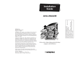
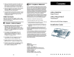
Installation Guide
AHA-1540CP/1542CP
ISA-to-SCSI Plug and Play
High-Performance Bus Master Host Adapter
with SCSISelect Utility
R
1 Introduction
This Installation Guide explains how to install and
configure Adaptec AHATM-1540CP/1542CP Plug
and Play ISA-to-SCSI high-performance bus master
host adapters. AHA-1540CP/1542CP host adapters
are fully Plug and Play compliant.
The AHA-1540CP/1542CP supports the SCSI
Configured Automatically (SCAM) protocol, which
assigns SCSI IDs dynamically and resolves SCSI ID
conflicts automatically. If your PC system includes
SCSI disk drives or other devices that support
SCAM, you do not need to manually assign SCSI IDs
to these devices.
This Installation Guide assumes that your PC system is
Plug and Play ready. You can make your PC Plug and
Play ready by installing Windows 95 or another
operating system with built-in Plug and Play
support.
AHA-1540CP/1542CP host adapters are also fully
functional in non-Plug and Play PCs. See the
AHA-1540CP/1542CP User’s Guide for more detailed
information on installing the host adapter in Plug
and Play or non-Plug and Play PCs.
Caution: Keep the host adapter in its conductive wrapping until you are ready to install it
in your PC. Before handling the host
adapter, always ground yourself by touching an unpainted surface on your PC chassis.
1
Host Adapter Layout
This diagram shows the major AHA-1540CP/
1542CP components. The following table describes
each component:
J1
J2
J3
J4
S1
Label
J1
J2
J3
Description
External LED Connector
Floppy Drive Connector1
Internal SCSI Connector
1 AHA-1542CP
Label Description
J4 External SCSI Connector
S1 Switch Block
only.
2
Default Settings
The AHA-1540CP/1542CP operates correctly with
the factory default settings in most PCs. Plug and
Play may override some settings when it assigns system resources. The default settings are listed in the
following table. See Host Adapter Switches on page 11,
and Configuring the SCSI Bus on page 8, to learn how
to change settings.
Settings from Switches:
Defaults
Plug and Play Functions
Enabled
I/O Port Address1
330h-333h
Floppy Controller (AHA-1542CP only)
Enabled
Host Adapter BIOS Address1 2
Enabled/ DC000h
Global Settings from SCSISelect:
Host Adapter Interrupt (IRQ) Channel1
IRQ 11
Host Adapter DMA Channel1
5
Host Adapter SCSI ID
7
SCSI Parity Checking
Enabled
DMA Transfer Rate
5.0 MBytes/sec
Host Adapter SCSI Termination
Automatic
Reset SCSI Bus at Power-on
Enabled
“Plug and Play” SCAM Support
Enabled
“Plug and Play” IRQ 9 and DMA 0 Support
Disabled
Host Adapter BIOS (Configuration Utility Reserves BIOS
Space)2
Enabled
Extended BIOS Translation for Drives >1 GByte2
Disabled
Support Removable Disks Under BIOS as Fixed Disks2
Boot Only
Dynamically Scan SCSI Bus for BIOS Devices2
Disabled
BIOS Support for More Than 2 Drives 2
Disabled
BIOS Support for INT 13h Extensions2
Enabled
BIOS Support for Bootable CD-ROMs2
Disabled
Immediate Return on Seek Command2
Enabled
Display <Ctrl><A> Messages during BIOS Initialization2
Enabled
Individual Device Settings from SCSISelect:
Enable Sync Negotiation
Yes
Enable Fast SCSI
Yes
Enable Disconnection
Yes
Send Start Unit Command 2
No
Include in BIOS Scan2 3
Yes
1 Settings may be overridden by Plug and Play during the boot process.
2 Settings are valid only if the host adapter BIOS is enabled. Host adapter
can be disabled from the switch and SCSISelect.
BIOS
3 Dynamically Scan SCSI Bus for BIOS Devices must be enabled for this option to
function.
3
2 Installing the Host Adapter
Follow these steps to insert the host adapter in a slot:
WARNING: Turn OFF and disconnect the
power to your PC and attached devices. See
your PC’s documentation for instructions.
1 Remove the PC chassis cover to expose the expansion slots and expansion slot covers.
2 Identify an empty ISA expansion slot.
3 Remove the corresponding expansion slot cover
from the rear opening on the PC chassis.
4 Change host adapter switch settings, if necessary.
Here are some reasons you might need to do this.
(See Host Adapter Switches on page 11, for more
information):
– If you are installing the host adapter in a nonPlug and Play PC, you may need to change its
I/O port address and/or BIOS address if they
are already used by another board or device.
– Disable the AHA-1542CP floppy controller if
you do not connect your floppy drives to it.
5 Align the bus connector on the bottom of the host
adapter with the slot and carefully insert it into
the slot.
4
6 Attach the host adapter bracket to the PC chassis
with the expansion slot cover screw.
Note: Do not replace the PC chassis cover or
reconnect the power yet.
3 Connecting SCSI Devices
This section explains how to connect SCSI disk
drives, CD-ROM drives, and other kinds of SCSI
devices to your AHA-1540CP/1542CP host adapter.
Caution: AHA-1540CP/1542CP host adapters support only single-ended SCSI devices.
Do not connect differential SCSI devices to the
host adapter. Read the device documentation to determine whether a SCSI device is
single-ended or differential.
Connecting Internal SCSI Devices
You can use the internal SCSI cable included with
your host adapter to connect up to two internal SCSI
devices. If you want to install more than two internal
SCSI devices, you must get a 50-pin internal SCSI
cable with enough connectors for all devices.
1 Enable termination on the internal SCSI device
that will be at the end of the cable farthest from
the host adapter. Read the device documentation
to determine how to do this.
2 Plug the 50-pin female connector on one end of
the internal cable into the host adapter’s internal
SCSI connector, J3.
Note: Be sure to match pin 1 on the cable
with pin 1 on the host adapter’s internal
SCSI connector. Pin 1 is marked with a contrasting color on one edge of the ribbon
cable. Pin 1 is marked with a 1 on the host
adapter SCSI connector, J3.
5
3 Plug the last connector on the ribbon cable into
the connector of the closest internal SCSI device.
Maintain pin-1 orientation.
4 Plug the middle connector on the SCSI cable into
the connector of the second internal SCSI device,
if there is one. Maintain pin-1 orientation.
Connecting External SCSI Devices
1 Attach the connector of a 50-pin, high-density
external SCSI cable to the host adapter’s external
SCSI connector, J4. (External cables can only be
plugged in one way, so pin-1 orientation is
automatic.)
2 Plug the other end of the cable into one of the
SCSI connectors on the back of the first external
SCSI device.
3 If you have more than one external device, plug
one end of an external cable into the first device’s
other SCSI connector. Plug the other end of this
cable into a SCSI connector on the next external
device. Link all external devices like this.
4 Insert an active standard or an active passthrough
terminator plug into the SCSI connector on the
last external SCSI device. Read the device documentation if you need more information.
Note: By default, the host adapter sets its
own termination automatically. You only
need to be concerned with setting termination on the other SCSI devices.
Assigning SCSI IDs
Each SCSI disk drive, CD-ROM drive, or other SCSI
device must have a unique SCSI ID. Some newer
SCSI disk drives support SCAM (SCSI Configured
Automatically). The SCAM software included with
your host adapter automatically assigns SCSI IDs to
these devices when you boot your PC.
Some SCSI devices allow SCAM to read their SCSI
IDs, which are set via jumpers or switches, but do
not allow SCAM to change the IDs dynamically.
6
SCAM cannot change or read the SCSI IDs of some
older SCSI devices. If you have any such devices and
SCAM is enabled on the host adapter, your PC may
hang if SCAM tries to assign SCSI IDs that are
already in use. If this is the case, you must disable
SCAM functions with the SCSISelect™ utility (see
Configuring the SCSI Bus on page 8) and set SCSI IDs
manually for all devices. See your SCSI device documentation to determine how, or if, your SCSI devices
support SCAM.
If you need to set SCSI IDs with switches or jumpers,
assign 0 and 1 to the first two SCSI hard disk drives.
The host adapter is set to SCSI ID 7 by default and
should not be changed.
4 Connecting Floppy Drives (AHA-1542CP)
Follow these steps to connect floppy drives mounted
inside the PC chassis to the host adapter. Use the
34-pin floppy ribbon cable already in your PC.
Note: If you do not use the floppy controller
on the AHA-1542CP, disable switch sw5; see
Host Adapter Switches on page 11.
1 Attach the connector on the 34-pin floppy ribbon
cable (farthest from the twist in the cable) to the
host adapter’s floppy connector, J2. Maintain
pin-1 orientation.
2 Attach the connector located closest to the twist of
the floppy ribbon cable to the first floppy drive.
The twist in the cable designates drive A. Maintain pin-1 orientation.
3 Attach the middle connector of the floppy ribbon
cable to the second floppy drive (drive B). Maintain pin-1 orientation.
4 If necessary, disable the floppy controller on the
PC’s motherboard or disk controller. See your PC
documentation for details.
7
5 Reassembling and Starting the PC
Follow these steps to reassemble and power the PC:
1 Check SCSI cable connections. They may have
been loosened if you had to change switch settings on the SCSI device(s).
2 Replace the PC chassis cover, following the
instructions in your PC’s documentation.
3 Be sure all power switches are OFF, then reconnect the power cables to your PC.
4 Turn ON the power for the external SCSI devices,
and then turn ON the PC.
At system bootup the host adapter BIOS sign-on
message appears on the monitor. The host adapter
finds devices on the SCSI bus and assigns SCSI IDs
to SCAM devices.
6 Configuring the SCSI Bus
Your host adapter includes the SCSISelect utility,
which lets you change SCSI configuration settings
without opening your PC or editing configuration
files. In a Plug and Play system you seldom need to
change the default settings. However, you may want
to change some SCSI features for particular devices
to optimize performance or use the formatting or
diagnostic utilities.
Running the SCSISelect Utility
If the AHA-1540CP/1542CP onboard BIOS is
enabled with switches, you can start the SCSISelect
utility by pressing Ctrl-A when the prompt appears
at boot time. (The default for the BIOS is enabled.)
Also, an executable version of SCSISelect
(cpconfig.exe) is available on the Adaptec BBS. The
BBS phone number is listed on page 12 of this Installation Guide.
Use the ↑, ↓, and Enter keys to make selections. Press
Esc to return to the previous menu. Press F6 to
restore the originally manufactured SCSISelect
default values. To abandon changes made, press Esc
and select No when prompted to save the changes.
8
If you have multiple AHA-1540CP/1542CP host
adapters in your computer, use the SCSI Disk Utilities to determine which host adapter you are
configuring.
Configure/View Host Adapter Settings
The Configuration screen displays these options:
Host Adapter Interrupt (IRQ) Channel, Host
Adapter DMA Channel, Host Adapter SCSI ID, SCSI
Parity Checking, DMA Transfer Rate, and Host
Adapter SCSI Termination. Highlight an option and
press Enter to select the value.
Select SCSI Device Configuration to modify the following options for each device on the SCSI bus:
Enable Synchronous Negotiation, Enable Fast SCSI,
Enable Disconnection, Send Start Unit Command,
and Include in BIOS Scan. You can set these options
individually for each device on the SCSI bus.
Select Advanced Configuration Options to modify
the remaining advanced options as listed on page 3.
Do not change these options unless you fully understand what they mean.
SCSI Disk Utilities
Select SCSI Disk Utilities from the Main menu to
view a list of installed SCSI devices. When you select
a device, the Utilities menu appears.
Format Disk runs the Adaptec SCSI low-level format utility. Verify Disk Media scans the selected
device’s media for defects. If it finds bad blocks, it
prompts you to reassign them.
Host Adapter Diagnostics
The Host Adapter Diagnostics option allows you to
perform a Bus Master DMA test on your PC’s memory. Not all PC systems are fully ISA compatible and
properly support Bus Master DMA transferswhich are necessary for optimized performance
under multitasking operating systems like OS/2,
Windows 95, and NetWare.
The diagnostic program performs a memory transfer
test and then repeats the process. If the test fails, try
changing the DMA transfer rate to a lower setting in
9
SCSISelect. You can stop the test at any time by pressing Esc. Your PC will reboot.
7 Operating System Software Support
Windows 95
Windows 95 has embedded software support for
your AHA-1540CP/1542CP host adapter. To install
your host adapter under Windows 95, read the
Microsoft documentation for installing new hardware devices. Adaptec EZ-SCSI™ has a number of
32-bit applications that enhance the usefulness of
your SCSI devices under Windows 95. These include
applications for power management, disk performance benchmarking, scanning documents and
graphics, and partitioning disks.
DOS/Windows 3.x
Adaptec EZ-SCSI automatically loads the additional
software support for the DOS/Windows 3.x operating systems if you want to do any of the following:
■
Install more than two hard drives in your PC with
the AHA-1540CP/1542CP under DOS prior to 5.0
■
Install more than eight hard drives (seven per
host adapter) in your PC with the AHA-1540CP/
1542CP under DOS 5.0 and above
■
Use a CD-ROM drive, scanner, or SCSI tape drive
■
Remove and insert CD-ROMs and other removable media while your PC is running
To order EZ-SCSI and other Adaptec software products, call the phone number listed on page 12.
Other Operating Systems
Netware, Windows NT, OS/2, and various versions
of UNIX have embedded drivers to support the
AHA-1540CP/1542CP. Contact Adaptec or your
operating system vendor for information on
AHA-1540CP/1542CP drivers for these operating
systems. Plug and Play functions may not work on
these operating systems; however, you can use the
AHA-1540CP/1542CP as a standard (non-Plug and
Play) host adapter.
10
8 Troubleshooting Checklist
If a problem occurs during installation, check these
items first:
■
Are the power cables and SCSI interface cables
properly connected?
Connect internal devices to your computer’s
power supply; plug external device power cables
into a grounded line power outlet. Follow the
instructions in the hardware documentation.
■
Is the host adapter firmly seated and secured in a
16-bit expansion bus slot?
■
Is pin-1 orientation maintained throughout the
SCSI bus?
■
Is each SCSI device, including the host adapter,
set to a unique SCSI ID?
■
Is SCSI termination set correctly?
9 Host Adapter Switches
If you have a Plug and Play system, you do not need
to change any of these switch settings. However, the
settings are listed in the table below for your reference (*=default setting; off=open).
Plug and Play
sw1
Floppy Controller
sw5
Enabled*
Off
Enabled*
Off
Disabled
On
Disabled
On
I/O Port Address sw2 sw3 sw4 BIOS Address
sw6 sw7 sw8
330h to 333h*
Off
Off
Off DC000h*
Off
Off
Off
334h to 337h
On
Off
Off D8000h
On
Off
Off
230h to 233h
Off
On
Off D4000h
Off
On
Off
234h to 237h
On
On
Off D0000h
On
On
Off
130h to 133h
Off
Off
On
CC000h
Off
Off
On
134h to 137h
On
Off
On
C8000h
On
Off
On
Reserved
Off
On
On
Reserved
Off
On
On
On
On
On
Reserved
On
On
On
1
BIOS Disabled
1 If you disable the onboard BIOS, you cannot boot your PC from a SCSI drive con-
nected to the host adapter or run SCSISelect by pressing Ctrl-A at bootup. If you
are installing more than one host adapter in your PC, only one host adapter BIOS
should be enabled—the one that controls the boot device.
11
10 Adaptec Customer Support Services
If you have questions about installing or using the host adapter,
check this install guide first—you will find answers to most of
your questions here. If you need further assistance, please contact
us. We offer the following support and information services:
■
For technical support (answers to technical questions, information about the Adaptec BBS, FTP and WWW Servers, and
access to the Interactive Fax system), call 800-959-SCSI (7274)
or 408-945-2550, 24 hours a day, 7 days a week. To speak with a
product support representative, call 408-934-SCSI (7274), M–F:
6:00 a.m. to 5:00 p.m., Pacific Time.
■
For sales information, call 800-959-SCSI (7274) or 408-945-2550,
M–F: 6:00 a.m. to 5:00 p.m., Pacific Time.
■
The Adaptec Electronic Bulletin Board Service (BBS) provides
information on software upgrades, answers to common questions, and other topics. The BBS is available 24 hours a day, 7
days a week, at 408-945-7727; 1200/2400/9600/14,400/28,800
baud, 8 data bits, 1 stop bit, no parity.
■
The Adaptec FTP and WWW Servers provide information on
software upgrades, product literature, answers to common
questions, and other topics. The FTP and WWW Servers are
available from the Internet 24 hours a day, 7 days a week, at
ftp.adaptec.com and http://www.adaptec.com.
■
The Adaptec Interactive Fax system provides answers to common questions, product literature, and current information
about Adaptec products and services. The Adaptec Interactive
Fax system is available 23 hours a day, 7 days a week. The Fax
system is out of service 1 hour each day. You can call this service directly at 408-957-7150.
■
To order Adaptec software and SCSI cables, call 800-442-SCSI
(7274) or 408-957-SCSI (7274), M–F: 6:00 a.m. to 5:00 p.m.,
Pacific Time.
■
To request additional documentation for Adaptec products,
call 800-934-2766 or 510-732-3829, M–F: 6:00 a.m. to 5:00 p.m.,
Pacific Time.
12
FCC Compliance Statement
NOTE: This equipment has been tested and found to comply with the limits
for a Class B digital device, pursuant to Part 15 of the FCC rules. These limits are designed to provide reasonable protection against harmful interference in residential installations. This equipment generates, uses, and can
radiate radio frequency energy, and if not installed and used in accordance
with the instructions, may cause harmful interference to radio communications. However, there is no guarantee that interference will not occur in a
particular installation.
If this equipment does cause interference to radio or television equipment
reception, which can be determined by turning the equipment off and on,
the user is encouraged to try to correct the interference by one or more of
the following measures:
•
•
•
•
Reorient or relocate the receiving antenna
Move the equipment away from the receiver
Plug the equipment into an outlet on a circuit different from that to
which the receiver is powered
If necessary, the user should consult the dealer or an experienced radio/
television technician for additional suggestions
CAUTION: Only equipment certified to comply with Class B (computer
input/output devices, terminals, printers, etc.) should be attached to this
equipment, and must have shielded interface cables.
Finally, any changes or modifications to the equipment by the user not
expressly approved by the grantee or manufacturer could void the user’s
authority to operate such equipment.
Each host adapter is equipped with an FCC compliance label that shows
only the FCC identification number. The full text of the associated label
follows:
This device complies with part 15 of the FCC rules. Operation is subject to
the following two conditions: (1) this device may not cause harmful interference and (2) this device must accept any interference received, including
interference that may cause undesired operation.
Adaptec, Inc.
691 South Milpitas Blvd.
Milpitas, CA 95035
Copyright © 1994, 1995 Adaptec, Inc. All rights reserved.
Adaptec, the Adaptec logo, AHA, EZ-SCSI, and SCSISelect are
trademarks of Adaptec, Inc. which may be registered in some
jurisdictions. All other trademarks are owned by their respective
owners.
Printed in Singapore
Stock No.: 510628-00, Rev. B LL 4/95
Information subject to change without notice.
13