1
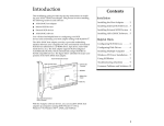
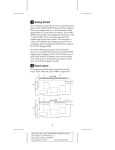
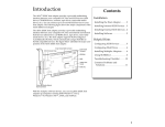
Installation Guide AHA-3940AUWD MultiChannel PCI-to-UltraSCSI Host Adapter with SCSISelect Utility R 1 Getting Started This Installation Guide tells you how to install and configure the AHA®-3940AUWD PCI-to-UltraSCSI host adapter. The host adapter has two SCSI channels which operate like two independent host adapters using the AIC-7895. The AHA-3940AUWD host adapter is designed for computers with 5-volt or 3.3-volt PCI slots. PCI is a local bus interface that enables highspeed data transfer. The computer in which you install the host adapter must be compliant with PCI 2.0 or higher. The AHA-3940AUWD supports up to fifteen 16-bit or 8-bit SCSI devices on each SCSI channel; up to seven of these can be 8-bit devices. 2 Board Layout The following diagram and table show the major AHA-3940AUWD components. J1 J4 J8 J5 J7 2 J6 J2 J3 Location Description J1 Internal 68 pin SCSI connector, Channel A J2 Internal 68 pin SCSI connector, Channel B J3 External LED connector J4 External 68 pin SCSI connector, Channel B1 J5 Internal 50pin SCSI connector, Channel A J6 J7 Multiple computer termination jumper, Channel B2 Multiple computer termination jumper, Channel A2 J8 External 68 pin SCSI connector, Channel A1 1 68-pin connector, very high density (0.8 mm) 2 See Termination in Multiple Computer Configurations on page 7. 3 3 Default Settings AHA-3940AUWD host adapters operate correctly with their factory default settings in most computers with PCI slots. The following table lists the settings and their default values. You can change these settings with the SCSISelect utility. (See Configuring the Host Adapter on page 9.) Global Settings for Host Adapter Host Adapter SCSI ID SCSI Parity Checking Host Adapter SCSI Termination Boot Device Options Boot Channel Boot SCSI ID Boot LUN Number1 Default Setting 7 Enabled Automatic Default Setting A First 0 0 Default Setting Yes (Enabled) 20 MBytes/sec2 SCSI Device Configurations Initiate Sync Negotiation Maximum Sync Transfer Rate Enable Disconnection Initiate Wide Negotiation Send Start Unit SCSI Command2 BIOS Multiple LUN Support2 Include in BIOS Scan Advanced Configuration Options Plug and Play SCAM Support Reset SCSI Bus at IC Initialization Extended BIOS Translation for DOS Drives > 1 GByte3 Host Adapter BIOS (Configuration Utility Reserves BIOS Space) Support Removable Disks under BIOS as Fixed Disks2 Display <Ctrl-A> Message During BIOS Initialization2 BIOS Support for Bootable CD-ROM2 BIOS Support for Int 13h Extensions2 1 Setting is valid only if Multiple LUN Support is enabled. 2 26.8, 32.0, 40.0 MBytes/sec is for Ultra devices only. 3 Settings are only valid if channel BIOS is enabled. 4 Yes (Enabled) Yes (Enabled) No (Disabled) No (Disabled) Yes (Enabled) Default Setting Enabled Enabled Enabled Enabled Boot Only Enabled Enabled Enabled 4 Installing the Host Adapter Inserting the Host Adapter in a PCI Slot WARNING: Turn OFF and disconnect the power to your computer and attached devices before you remove the cover of the computer. 1 Remove the cover from the computer case. 2 Locate an unused 5-volt or 3.3-volt PCI expansion slot that supports bus mastering. Make sure this slot is not obstructed by other system hardware. PCI bus slots are usually white or ivory and are shorter than ISA or EISA slots. Usually there are three PCI slots. One of these may be a shared slot. That is, it may have an ISA or EISA connector and a PCI connector, but only one kind of board can be inserted in the slot at any one time. 3 Remove the corresponding expansion slot cover from the computer chassis and save the screw. 4 Hold the host adapter directly over the bus master PCI slot and insert the end of the board in the card guide. Carefully press the bus connector on the bottom of the host adapter down into the slot. 5 Attach the host adapter bracket to the computer chassis with the screw from the expansion slot cover that you removed. Note: Do not replace the computer cover or reconnect the power yet! 5 5 Connecting SCSI Devices Caution: AHA-3940AUWD host adapters support only single-ended SCSI devices. Do not connect differential SCSI devices, because they may damage the host adapter. Read the SCSI device documentation to determine if the device is single-ended or differential. Connecting SCSI Cables SCSI devices are cabled together in a single, connected series called the SCSI bus. 1 Lay out the cables and find the pin-1 element of each cable and device connector. On internal cables, pin 1 is usually marked with a contrasting color on one edge of the ribbon cable, and a small triangle or number 1 marks pin 1 on the SCSI connector. External cables can only be plugged in one way, so pin-1 orientation is automatic. 2 Attach the SCSI cable(s) to the host adapter and the device(s), using the internal and/or external connector(s). Be sure to maintain correct pin-1 orientation throughout the bus for each channel. The AHA-3940AUWD host adapter has two external connectors (J4 and J8) and three internal connectors (J1, J5, and J2), as shown in the diagram on page 2. If you are connecting 8-bit SCSI devices to channel B of an AHA-3940AUWD, you will need 68-pin-to-50-pin converters. The following table shows the maximum SCSI cable length you can use for each combination of device types and number of SCSI devices. Device Type Number of Devices Max Cable Total Length SCSI-1 Up to 14 6.0m (19.7 feet) SCSI-2 and/or SCSI-1 Up to 14 3.0m (9.8 feet) Ultra(SCSI-3) and/or SCSI-2 Up to 4 3.0m (9.8 feet) Ultra(SCSI-3) and/or SCSI-2 Up to 14 1.5m (4.9 feet) 6 Caution: Channel A has three SCSI connectors: J1, J5, and J8. Do not connect devices to all three connectors at one time. At most, only two of the three channel A connectors can be used at the same time. Terminating the SCSI Bus The last physical SCSI device on each end of the SCSI bus must be terminated. Termination must be disabled on all other devices in the middle of the SCSI bus. You may need to change the termination setting on some devices in your computer system. Terminating the Host Adapter Host adapter termination is controlled by the SCSISelect utility. The default setting is Automatic, which works like this: ■ If the host adapter detects that devices are attached to at least two connectors on channel A, it disables its terminators. Otherwise, the terminators are enabled. If the 50-pin connector is used, the high byte termination is always enabled. ■ Termination for Channel B is the same as channel A, except that the internal 50-pin connector does not apply. If you need to change host adapter termination, complete the physical installation, then run SCSISelect as described in Configuring the Host Adapter on page 9. Termination in Multiple Computer Configurations If you are setting up your SCSI bus so that SCSI devices are shared by host adapters in two different computers, you can enable your host adapter to provide termination power even when one computer is powered OFF. To do this, place a jumper shunt on jumper J7 if the second computer is connected to SCSI Channel A or on jumper J6 if the second computer is connected to SCSI Channel B. This feature works only when one computer is turned off, and the other computer connected to the 7 same SCSI bus accesses the disk drives and other SCSI devices on the bus. Setting SCSI IDs You must assign a different SCSI ID to each device on each of the SCSI buses connected to the AHA-3940AUWD host adapter. See your SCSI device documentation to learn how to determine the ID and change it. ■ ID 7 is the default SCSI ID for the host adapter on both SCSI Channels A and B. You can change the ID(s) in SCSISelect, if necessary. See Configuring the Host Adapter on page 9. ■ SCSI devices that are connected to channel A and use the 50-pin connector should have IDs from 0 to 7. SCSI devices that are connected to the 68-pin connector should have IDs from 0 to 15. (The host adapter itself uses one SCSI ID on each channel.) ■ The SCSI IDs on one SCSI channel do not interfere with the IDs on another SCSI channel. ■ If two host adapters are connected to the same SCSI bus, be sure to assign them different SCSI IDs, preferably IDs 7 and 6. 6 Completing the Installation 1 Put the cover back on the computer, following the directions in the documentation. 2 Be sure all power switches are OFF, then reconnect power cables to your computer. 3 Turn ON the power for the peripheral device(s) and then for the computer. 4 If your system CMOS Setup requires you to enable PCI bus parameters, do so now. Refer to your computer documentation. 8 Note: The PCI bus is supposed to automatically assign Interrupt channels (IRQs) and port addresses. But because PCI is currently combined with other bus architectures such as ISA and EISA, you may need to edit the PCI bus parameters in your CMOS Setup. When the computer boots, the host adapter BIOS sign-on message appears on the screen. This message includes a list of installed SCSI devices and information about the BIOS. In most cases your computer, host adapter, and SCSI devices are ready to use, and you do not need to run SCSISelect. 7 Configuring the Host Adapter Your AHA-3940AUWD host adapter includes the built-in SCSISelect configuration utility. SCSISelect lets you change host adapter settings, such as SCSI Parity Checking and Host Adapter SCSI ID, without opening your computer or flipping switches. To run SCSISelect, press Ctrl-A immediately when the SCSISelect message appears on the screen at the time your computer boots. Use the arrow (↑↓) and Enter keys to make selections in the SCSISelect Options menu. Press Esc at any time to return to the previous menu. You can press F6 to restore the original default settings. To abandon changes you made in the Configure/View Host Adapter Settings menu, press Esc and select No when asked if you want to save the changes. The first SCSISelect screen asks you to choose SCSI Channel A or Channel B. You can only configure one SCSI channel at a time. If you have multiple host adapters, the screen displays a list of SCSI channels for all installed host adapters. Configure/View Host Adapter Settings The Configuration screen displays the basic options for each SCSI channel: Host Adapter SCSI ID, SCSI Parity Checking, Host Adapter SCSI Termination, Boot Device Options, SCSI Device Configuration, 9 and Advanced Configuration Options. Highlight an option and press Enter to see a list of possible values. Select SCSI Device Configuration to see a menu of the following options for each device on the SCSI bus: Initiate Sync Negotiation, Maximum Sync Transfer Rate, Enable Disconnection, Initiate Wide Negotiaton, Send Start Unit Command, BIOS Multiple LUN Support, and Include in BIOS Scan. These settings apply to individual SCSI devices. Select Advanced Configuration Options for a menu that includes these advanced options: Plug and Play SCAM Support, Reset SCSI Bus at IC Initialization, Extended BIOS Translation for DOS Drives > 1 GByte, Host Adapter BIOS (Configuration Utility Reserves BIOS Space), Support Removable Disks as Fixed Disks, Display <Ctrl-A> Message During BIOS Initialization, BIOS Support for Bootable CD-ROM, and BIOS Support for Int 13h Extensions. For more details please refer to the table on page 3. SCSI Disk Utilities When you select SCSI Disk Utilities from the Options menu, a list of installed SCSI devices appears. When you select a device the Utilities menu appears, giving you the following two choices: ■ Format Disk—runs the Adaptec SCSI low-level format utility. Most SCSI devices are preformatted and do not need to be formatted again. ■ Verify Disk Media—scans the selected device’s media for defects. If bad blocks are found, you are prompted to reassign them; if you select Yes, those blocks are no longer used. 8 Operating System Software Under MS-DOS 5.0 or later, you can install up to eight hard disk drives (SCSI or non-SCSI) in your computer without using additional software. Older versions of DOS support up to two hard disk drives. You can make the host adapter treat removablemedia drives as hard disk drives. To do this, run the SCSISelect utility, select Advanced Configuration 10 Options, and set the Support Removable Disks Under BIOS as Fixed Disks option to All Disks. Caution: If you use this setting, you cannot remove media while your computer is ON. You need additional software if you want to do the following (contact Adaptec for additional drivers): ■ Use devices other than hard disk drives, such as SCSI tape drives, CD-ROM drives, scanners, etc. ■ Remove and insert CD-ROM discs and other removable media while your computer is running ■ Support more than eight hard disk drives under MS-DOS 5.0 or later Adaptec EZ-SCSI Software Adaptec EZ-SCSI software provides support for DOS, Windows 3.x, Windows 95, and Windows NT™. Use the menu-driven software to install drivers and configure your DOS/Windows operating system automatically. Contact Adaptec if you need these drivers. Other Operating Systems The Adaptec 7800 Family Manager Set provides support for Novell NetWare, OS/2, SCO Unix, and SCO UnixWare. Contact Adaptec if you need these drivers. 9 Troubleshooting Checklist If you have a problem during installation, check these items first: ■ Is your computer compliant with PCI 2.0 or higher? ■ Are all SCSI devices powered? ■ Are all SCSI bus cables and power cables properly connected? ■ Does the host adapter and each device on each SCSI bus channel have a unique SCSI ID? 11 ■ Are all devices on the SCSI bus terminated properly? ■ Does your system CMOS Setup require you to enable PCI bus parameters? If so, see your computer documentation. Confirm the IRQ channel assignment. ■ Is the host adapter installed in a PCI slot that supports bus mastering? Refer to your computer documentation or move the host adapter to a different PCI slot. Computer Will Not Boot from a SCSI Disk Drive If both SCSI and non-SCSI disk drives are installed in your computer, the non-SCSI drive is always the boot device. If the computer has only SCSI disk drives, check the following: 1 Make sure your computer’s CMOS Setup is set to No Drives Installed. 2 Make sure the boot partition of the boot hard disk is active. 3 Partition the disk. See the MS-DOS User’s Guide for instructions. If nothing else works, back up all data on the SCSI hard disk and perform a low-level format with the SCSISelect Format Disk option. 10 Product Support Please refer to your Adaptec Sales Agreement or contact your Adaptec sales representative for information on how to obtain product support. 12 Federal Communications Commission Radio Frequency Interference Statement WARNING: Changes or modifications to this unit not expressly approved by the party responsible for compliance could void the user’s authority to operate the equipment. This equipment has been tested and found to comply with the limits for a Class B digital device, pursuant to Part 15 of the FCC rules. These limits are designed to provide reasonable protection against harmful interference in a residential installation. This equipment generates, uses, and can radiate radio frequency energy, and if not installed and used in accordance with the instruction manual, may cause harmful interference to radio communications. However, there is no guarantee that interference will not occur in a particular installation. However, if this equipment does cause interference to radio or television equipment reception, which can be determined by turning the equipment off and on, the user is encouraged to try to correct the interference by one or more of the following measures: • Reorient or relocate the receiving antenna. • Increase the separation between equipment and receiver. • Connect the equipment to an outlet on a circuit different from that to which the receiver is connected. • Consult the dealer or an experienced radio/television technician for help. Use a shielded and properly grounded I/O cable and power cable to ensure compliance of this unit to the specified limits of the rules. This device complies with part 15 of the FCC rules. Operation is subject to the following two conditions: (1) this device may not cause harmful interference and (2) this device must accept any interference received, including interference that may cause undesired operation. Adaptec, Inc. AHA-3940AUWD Tested To Comply With FCC Standards FOR HOME OR OFFICE USE Canadian Compliance Statement This Class B digital apparatus meets all requirements of the Canadian Interference-Causing Equipment Regulations. Cet appareil numérique de la classe B respecte toutes les exigences du Règlement sur le matérial brouilleur du Canada. 13 Adaptec, Inc. 691 South Milpitas Blvd. Milpitas, CA 95035 Copyright © 1997, Adaptec, Inc. All rights reserved. Adaptec, the Adaptec logo, AHA, and EZ-SCSI are trademarks of Adaptec, Inc. which may be registered in some jurisdictions. Windows NT is a trademark, and Windows and Windows 95 are registered trademarks of Microsoft Corporation used under license. All other trademarks used are owned by their respective owners. Printed in Singapore Stock No.: 511396-00, Rev. A MR 3/97 Micronics Computers Inc., P/N: 06-10013-00 Information subject to change without notice. 14