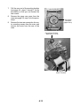
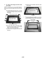
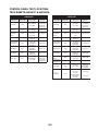
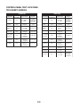
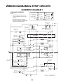
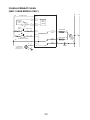
1
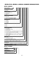
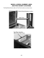
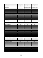
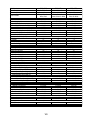
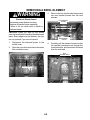
CONSUMER SERVICES TECHNICAL
EDUCATION GROUP PRESENTS
KR-30
ELECTRIC
BUILT-IN
DOUBLE OVEN
JOB AID
Part No. 8178007
FORWARD
This Job Aid, “Whirlpool Electric Built-In Double Oven,” (Part No. 8178007), provides the technician
with information on the installation and service of the Whirlpool Electric Built-In Double Oven. It is
to be used as a training Job Aid and Service Manual. For specific information on the model being
serviced, refer to the “Use and Care Guide,” or “Tech Sheet” provided with the Whirlpool Electric
Built-In Double Oven.
The Wiring Diagrams and Strip Circuits used in this Job Aid are typical and should be used for
training purposes only. Always use the Wiring Diagram supplied with the product when servicing
the unit.
GOALS AND OBJECTIVES
The goal of this Job Aid is to provide detailed information that will enable the service technician to
properly diagnose malfunctions and repair the Whirlpool Electric Built-In Double Oven.
The objectives of this Job Aid are to:
• Understand and follow proper safety precautions.
• Successfully troubleshoot and diagnose malfunctions.
• Successfully perform necessary repairs.
• Successfully return the Electric Built-In Double Oven to its proper operational status.
WHIRLPOOL CORPORATION assumes no responsibility for any repair made
on our products by anyone other than Authorized Factory Service Technicians.
Copyright 2001, Whirlpool Corporation, Benton Harbor, MI 49022
- ii -
Table of Contents
Page
SPECIFICATIONS .................................................................................................................. 1-1
INSTALLATION HIGHLIGHTS ................................................................................................ 2-1
Electrical Supply Requirements ......................................................................................... 2-1
Removing & Reinstalling The Oven Door .......................................................................... 2-3
PRODUCT OPERATION ........................................................................................................ 3-1
Air Flow .............................................................................................................................. 3-1
The Oven Shutdown Thermal Fuse & Control Panel Thermal Fuse ................................. 3-2
The Oven Door Latch Assembly ........................................................................................ 3-3
How The Self-Clean Cycle Works ..................................................................................... 3-4
COMPONENT ACCESS ......................................................................................................... 4-1
Component Locations ........................................................................................................ 4-1
Removing The Thermal Fuse, The Oven Control/Display Boards,
And The Touch Panel Assembly .................................................................................... 4-2
Removing The Power Supply Wiring Terminal Block
And The Upper & Lower Blower Motors ......................................................................... 4-4
Removing The Upper & Lower Oven Door Latch Assembly.............................................. 4-6
Removing An Oven Light & An Oven Temperature Sensor .............................................. 4-8
Removing A Broil Element ................................................................................................. 4-9
Removing A Bake Element .............................................................................................. 4-10
Removing An Oven Shutdown Thermal Fuse ................................................................. 4-11
Removing The Convection Fan Motor Assembly ............................................................ 4-12
Removing The Oven Door Glass, Hinges, & Handle ....................................................... 4-14
Removing The Oven Door Gasket ................................................................................... 4-16
COMPONENT TESTING ........................................................................................................ 5-1
Blower Motors .................................................................................................................... 5-1
Oven Temperature Sensor ................................................................................................ 5-1
Convection Fan Motor ....................................................................................................... 5-2
Oven Shutdown Thermal Fuse .......................................................................................... 5-2
Broil Element ..................................................................................................................... 5-3
Bake Element .................................................................................................................... 5-3
Oven Door Latch Assembly ............................................................................................... 5-4
Control Panel Thermal Fuse .............................................................................................. 5-4
DIAGNOSIS & TROUBLESHOOTING .................................................................................... 6-1
Diagnostics ........................................................................................................................ 6-1
Fahrenheit To Celsius Conversion .................................................................................... 6-1
Programming The Cavity Size ........................................................................................... 6-1
Electrostatic Discharge Sensitive Electronics .................................................................... 6-1
Failure/Error Display Codes—Tech Sheets 4451887C & 4451888A ................................ 6-2
Failure/Error Display Codes—Tech Sheet 4452022A ....................................................... 6-3
Relay Logic Chart—Tech Sheets 4451887C & 4451888A ................................................ 6-4
Relay Logic Chart—Tech Sheet 4452022A ....................................................................... 6-4
Control Panel Test Locations—Tech Sheets 4451887C & 4451888A .............................. 6-5
Control Panel Test Locations—Tech Sheet 4452022A ..................................................... 6-6
- iii -
Page
WIRING DIAGRAMS & STRIP CIRCUITS .............................................................................. 7-1
Schematic Diagram 1 (Tech Sheet 4451887C) ................................................................. 7-1
Strip Circuits ...................................................................................................................... 7-2
Schematic Diagram 2 (Tech Sheet 4451888A) ................................................................. 7-4
Strip Circuits ...................................................................................................................... 7-5
Schematic Diagram 3 (Tech Sheet 4452022A) ................................................................. 7-7
Strip Circuits ...................................................................................................................... 7-8
Tech Sheet / Model Number Usage Charts ..................................................................... 7-10
TECH TIPS ............................................................................................................................. 8-1
- iv -
WHIRLPOOL MODEL & SERIAL NUMBER DESIGNATIONS
MODEL NUMBER
MODEL NUMBER
INTERNATIONAL SALES IND.
OR MARKETING CHANNEL
IF PRESENT
G
B
D
27
7
P
D
S
PRODUCT GROUP
G = WHIRLPOOL GOLD
R = ELECTRIC
S = GAS
PRODUCT IDENTIFICATION
B = BUILT-IN
M = BUILT-IN MICROWAVE COMBO
S = BUILT-IN HIGH-SPEED COMBO
CONFIGURATION
S = SINGLE
D = DOUBLE
C = COMBO
OVEN SIZE
24 = 24˝
27 = 27˝
30 = 30˝
FEATURE VARIATIONS
0 = STANDARD
2 = CONTINUOUS CLEAN
3 = EASY CLEAN
5 = S/C SINGLE & S/C STD DOUBLE & MWC-S/C COMBO
6 = S/C-S/C DOUBLE & CRISP S/C COMBO
7 = CONVECTION SINGLE, S/C-CONV. DOUBLE & CRISP
CONV. COMBO
8 = CONV.-CONV. DOUBLE & CONV.-CONV. COMBO
9 = MULTIMODE
DOOR TYPE
B = SOLID BLACK GLASS
P = PANORAMIC WINDOW GLASS
YEAR OF INTRODUCTION
D = 1995, G = 1998, H = 1999, J = 2000, K = 2001
COLOR CODE
B = BLACK, Z = ALMOND, Q = WHITE, S = STAINLESS, T = BISCUIT
ENGINEERING CHANGE (0, 1, 2, ETC.)
SERIAL NUMBER
SERIAL NUMBER
MANUFACTURING SITE
X = OXFORD
YEAR OF PRODUCTION
K = 2000, L = 2001, M = 2002
WEEK OF PRODUCTION
41st WEEK
PRODUCT SEQUENCE NUMBER
X
K
41
01002
-v-
0
MODEL & SERIAL NUMBER LABEL
AND TECH SHEET LOCATIONS
The Model/Serial Number label and Tech Sheet locations are shown below.
Model & Serial Number Location
Upper Oven
Tech Sheet Location
(Below Top Front Cover)
- vi -
IMPORTANT SAFETY INFORMATION
Your safety and the safety of others is very important.
Important safety messages have been provided in this Job Aid. Always read and obey all
safety messages.
This is the safety alert symbol.
This symbol alerts you to hazards that can kill or hurt you and others.
All safety messages will be preceded by the safety alert symbol and the word
“WARNING.”
All safety messages will identify the hazard, tell you how to reduce the chance of injury, and tell
you what can happen if the instructions are not followed.
IMPORTANT
Electrostatic Discharge (ESD)
Sensitive Electronics
ESD problems are present everywhere. ESD may damage or weaken the electronic control assembly. The new control assembly may appear to work well after repair is finished,
but failure may occur at a later date due to ESD stress.
• Use an anti-static wrist strap. Connect the wrist strap to the green ground connection
point, or to an unpainted metal surface in the appliance.
- OR Touch your finger repeatedly to a green ground connection point, or to an unpainted
metal surface in the appliance.
• Before removing the part from its package, touch the anti-static bag to a green ground
connection point, or to an unpainted metal surface in the appliance.
• Avoid touching electronic parts, or terminal contacts. Handle the electronic control
assembly by the edges only.
• When repackaging the failed electronic control assembly in an anti-static bag, observe
the previous instructions.
- vii -
— NOTES —
- viii -
SPECIFICATIONS
Model Number
Model Description
Size-Configuration
Color Available
Dimensions/Specifications
Exterior Dimensions
Overall Height (in)
Overall Width (in)
Overall Depth Inc Hrdwr/Hndl (in)
Depth W/O Handle (in)
Cutout Dimensions
Cutout Height (in) (Measure Or Min/Max)
Cutout Width (in) (Measure Or Min/Max)
Cutout Depth (in) (Measure Or Min/Max)
Total Connected Load (In KW)
240 Volts
208 Volts
Circuit Amps
Oven Control Type
Interior
Main/Single Oven
Main Cleaning System
Main Self Clean Latch
Main Oven Liner Finish
Main Oven Height (in)
Main Oven Width (in)
Main Oven Depth (in)
Electric Element Output
Bake (W@240/208V)
Broil (W@240/208V)
Lower/Secondary Oven
Lower/Secondary Cleaning System
Lower/Secondary Auto Self Clean Latch
Lower/Secondary Oven Height (in)
Lower/Secondary Oven Width (in)
Lower/Secondary Oven Depth (in)
Lower/Secondary Electric Element Output
Lower/Secondary Bake (w@240/208v)
Lower/Secondary Broil (w@240/208v)
Miscellaneous
Product Literature
Cookbook Part/Comment
Installation Instructions Part/Comment
Service Manual Part/Comment
Tech Sheet Part/Comment
Use & Care Guide Oven Part/Comment
Other
Agency Approvals
Residential Use Only
Warranty
Full (Months)
GBD307PD
Double Built-In Oven
30"
GBD277PD
Double Built-In Oven
27"
Biscuit, Stainless
Stainless
51
29
25
23
1/8"
3/4"
1/8"
7/8"
51
26
25
23
1/8"
3/4"
1/8"
7/8"
RBD245PD
Double Built-In Oven
24"
Biscuit, White-On-White,
Black
51
23
25
23
1/8"
3/4"
1/8"
7/8"
49 3/4"
28 1/2"
23 1/4"
49 3/4"
25 1/2"
23 1/4"
49 3/4"
22 1/2"
23 1/4"
7.2
5.4
40
Electronic
7.2
5.4
40
Electronic
9.7
7.3
40
Electronic
Self Cleaning
Yes
Porcelain
16"
25"
18 1/2"
Self Cleaning
Yes
Porcelain
16"
22"
18 1/2"
Self Cleaning
Yes
Porcelain
16"
19"
18 1/2"
2000 W/ 1500 W
3000 W/ 2250 W
2000 W/ 1500 W
3000 W/ 2250 W
2000 W/ 1500 W
3000 W/ 2250 W
Self Cleaning
Yes
16"
25"
18 1/2"
Self Cleaning
Yes
16"
22"
18 1/2"
Standard
No
16"
19"
18 1/2"
2000 W/ 1500 W
3000 W/ 2250 W
2000 W/ 1500 W
3000 W/ 2250 W
2000 W/ 1500 W
3000 W/ 2250 W
4449237
4450411
8178007
4451887
4450569
4449237
4450410
8178007
4451887
4450569
N/A
4448969
8178007
4451887
4448976
UL
Yes
UL
Yes
UL, CSA
Yes
12
12
12
1-1
Model Number
Model Description
Size-Configuration
Color Available
Dimensions/Specifications
Exterior Dimensions
Overall Height (in)
Overall Width (in)
Overall Depth Inc Hrdwr/Hndl (in)
Depth W/O Handle (in)
Cutout Dimensions
Cutout Height (in) (Measure Or Min/Max)
Cutout Width (in) (Measure Or Min/Max)
Cutout Depth (in) (Measure Or Min/Max)
Total Connected Load (In KW)
240 Volts
208 Volts
Circuit Amps
Oven Control Type
Interior
Main/Single Oven
Main Cleaning System
Main Self Clean Latch
Main Oven Liner Finish
Main Oven Height (in)
Main Oven Width (in)
Main Oven Depth (in)
Electric Element Output
Bake (W@240/208V)
Broil (W@240/208V)
Lower/Secondary Oven
Lower/Secondary Cleaning System
Lower/Secondary Auto Self Clean Latch
Lower/Secondary Oven Height (in)
Lower/Secondary Oven Width (in)
Lower/Secondary Oven Depth (in)
Lower/Secondary Electric Element Output
Lower/Secondary Bake (w@240/208v)
Lower/Secondary Broil (w@240/208v)
Miscellaneous
Product Literature
Cookbook Part/Comment
Installation Instructions Part/Comment
Service Manual Part/Comment
Tech Sheet Part/Comment
Use & Care Guide Oven Part/Comment
Other
Agency Approvals
Residential Use Only
Warranty
Full (Months)
RBD275PD
Double Built-In Oven
27"
Biscuit, White-OnWhite, Black
51
26
25
23
1/8"
3/4"
1/8"
7/8"
RBD276PD
Double Built-In Oven
27"
RBD277PD
Double Built-In Oven
27"
Black, White-On -White
Black, White-On -White
51
26
25
23
1/8"
3/4"
1/8"
7/8"
51
26
25
23
1/8"
3/4"
1/8"
7/8"
49 3/4"
25 1/2"
23 1/4"
49 3/4"
25 1/2"
23 1/4"
49 3/4"
25 1/2"
23 1/4"
9.7
7.3
40
Electronic
9.7
7.3
40
Electronic
9.7
7.3
40
Electronic
Self Cleaning
Yes
Porcelain
16"
22"
18 1/2"
Self Cleaning
Yes
Porcelain
16"
22"
18 1/2"
Self Cleaning
Yes
Porcelain
16"
22"
18 1/2"
2000 W/ 1500 W
3000 W/ 2250 W
2000 W/ 1500 W
3000 W/ 2250 W
2000 W/ 1500 W
3000 W/ 2250 W
Standard
No
16"
19"
18 1/2"
Self Cleaning
Yes
16"
19"
18 1/2"
Self Cleaning
Yes
16"
22"
18 1/2"
2000 W/ 1500 W
3000 W/ 2250 W
2000 W/ 1500 W
3000 W/ 2250 W
2000 W/ 1500 W
3000 W/ 2250 W
N/A
4448970
8178007
4451887
4448976
N/A
4448970
8178007
4451887
4448976
N/A
4448969
8178007
4451887
4448976
UL, CSA
Yes
UL, CSA
Yes
UL, CSA
Yes
12
12
12
1-2
Model Number
Model Description
Size-Configuration
Color Available
Dimensions/Specifications
Exterior Dimensions
Overall Height (in)
Overall Width (in)
Overall Depth Inc Hrdwr/Hndl (in)
Depth W/O Handle (in)
Cutout Dimensions
Cutout Height (in) (Measure Or Min/Max)
Cutout Width (in) (Measure Or Min/Max)
Cutout Depth (in) (Measure Or Min/Max)
Total Connected Load (In KW)
240 Volts
208 Volts
Circuit Amps
Oven Control Type
Interior
Main/Single Oven
Main Cleaning System
Main Self Clean Latch
Main Oven Liner Finish
Main Oven Height (in)
Main Oven Width (in)
Main Oven Depth (in)
Electric Element Output
Bake (W@240/208V)
Broil (W@240/208V)
Lower/Secondary Oven
Lower/Secondary Cleaning System
Lower/Secondary Auto Self Clean Latch
Lower/Secondary Oven Height (in)
Lower/Secondary Oven Width (in)
Lower/Secondary Oven Depth (in)
Lower/Secondary Electric Element Output
Lower/Secondary Bake (w@240/208v)
Lower/Secondary Broil (w@240/208v)
Miscellaneous
Product Literature
Cookbook Part/Comment
Installation Instructions Part/Comment
Service Manual Part/Comment
Tech Sheet Part/Comment
Use & Care Guide Oven Part/Comment
Other
Agency Approvals
Residential Use Only
Warranty
Full (Months)
RBD305PD
Double Built-In Oven
30"
Biscuit, White-OnWhite, Black
51
29
25
23
1/8"
3/4"
1/8"
7/8"
RBD306PD
RBD307PD
Double Built-In Oven
Double Built-In Oven
30"
30"
Black, Almond-OnBlack, Almond-On-Almond,
Almond, White-On-White
White-On-White
51
29
25
23
1/8"
3/4"
1/8"
7/8"
51
29
25
23
1/8"
3/4"
1/8"
7/8"
49 3/4"
28 1/2"
23 1/4"
49 3/4"
28 1/2"
23 1/4"
49 3/4"
28 1/2"
23 1/4"
9.7
7.3
40
Electronic
9.7
7.3
40
Electronic
9.7
7.3
40
Electronic
Self Cleaning
Yes
Porcelain
16"
25"
18 1/2"
Self Cleaning
Yes
Porcelain
16"
25"
18 1/2"
Self Cleaning
Yes
Porcelain
16"
25"
18 1/2"
2000 W/ 1500 W
3000 W/ 2250 W
2000 W/ 1500 W
3000 W/ 2250 W
2000 W/ 1500 W
3000 W/ 2250 W
Standard
No
16"
25"
18 1/2"
Standard
No
16"
25"
18 1/2"
Self Cleaning
Yes
16"
25"
18 1/2"
2000 W/ 1500 W
3000 W/ 2250 W
2000 W/ 1500 W
3000 W/ 2250 W
2000 W/ 1500 W
3000 W/ 2250 W
4449066
4448975
8178007
4451887
4448976
4449066
4448975
8178007
4451887
4448976
4449066
4448975
8178007
4451887
4448976
UL, CSA
Yes
UL, CSA
Yes
UL, CSA
Yes
12
12
12
1-3
— NOTES —
1-4
INSTALLATION HIGHLIGHTS
ELECTRICAL SUPPLY REQUIREMENTS
• The oven must be connected with copper
wire only.
• Wire sizes and connections must conform to
the requirements of the National Electrical
Code, ANSI/NFPA 70—latest edition*, and
all local codes and ordinances. Wire sizes
and connections must conform with the rating of the appliance. Copies of the standards
listed above may be obtained from:
WARNING
Electrical Shock Hazard
• An electrical ground is required on this
appliance.
• Do not use an extension cord with this
appliance.
• If a cold water pipe is interrupted by plastic, nonmetallic gaskets, or other insulating materials, do not use for grounding.
• Do not ground to a gas pipe.
• Do not use a fuse in the neutral or grounding circuit. It could result in an electrical
shock.
• Check with a qualified electrician if you are
in doubt as to whether the appliance is
properly grounded.
Failure to follow these instructions could
result in death or serious injury.
* National Fire Protection Association
Batterymarch Park
Quincy, Massachusetts 02269
• The oven should be connected directly to a
time delay fuse or circuit breaker through
flexible, armored, or nonmetallic sheathed,
copper cable. The flexible, armored cable
that extends from the appliance should be
connected directly to the junction box.
• Fuse both sides of the line.
• Locate the junction box to allow as much
slack as possible between the junction box
and the appliance so that the appliance can
be moved if servicing is ever necessary. Do
not cut the conduit.
• A U.L.-listed conduit connector must be provided at the junction box.
• Wiring diagrams are located in Section 7 of
this Job Aid.
• A Tech Sheet is located below the top access cover on all models.
GENERAL
If codes permit, and a separate grounding wire
is used, it is recommended that a qualified electrician determine that the grounding path and
wire gauge are in accordance with local codes.
The following information applies to the builtin electric wall oven wiring:
• The oven must be connected to the proper
electrical voltage and frequency as specified
on the model/serial rating plate (located on
the upper oven frame).
• Models rated from 7.3 to 9.6 kW at 240-volts,
(5.5 to 7.2 kW at 208-volts), require a separate 40-ampere circuit. Models rated at 7.2
kW and below at 240-volts, (5.4 kW and
below at 208-volts), require a separate 30ampere circuit.
2-1
ELECTRICAL WIRING
If local codes DO permit connecting the cabinet-grounding conductor to a neutral junction
box wire, perform steps 6 and 7.
If local codes DO NOT permit connecting the
cabinet-grounding conductor to a neutral junction box wire, or if you are connecting the
appliance to a 4-wire electrical system, perform steps 8 through 11.
WARNING
Electrical Shock Hazard
• An electrical ground is required on this
appliance.
• Do not connect to the electrical supply
until the appliance is permanently
grounded.
• Turn off power to the junction box before
making the electrical connections.
• Connect the appliance to a grounded,
metallic, permanent wiring system.
Failure to follow these instructions could
result in death or serious injury.
1.
2.
3.
4.
5.
6.
Connect the factory-crimped bare and
white electrical wires coming from the
appliance conduit cable to the white (neutral) wire inside the junction box (see the
illustration below).
7. Replace the junction box cover.
8. Separate the factory-crimped bare and
white electrical wires coming from the
appliance conduit cable.
9. Connect the white appliance wire to the
white (neutral) wire inside the junction
box.
10. Connect the bare grounding wire from the
appliance to a grounded wire inside the
junction box. IMPORTANT: Do not connect the bare grounding wire to the
white (neutral) wire in the junction box.
11. Replace the junction box cover.
Insert the end of the flexible conduit through
the cabinet opening to the junction box
inlet.
Disconnect the power going to the junction box.
Open the junction box cover and connect
the flexible conduit to the U.L.-listed conduit connector.
Connect the ends of the black wires together with twist-on connectors (see the
illustration below).
Connect the ends of the red wires together
with twist-on connectors.
cable from
power supply
junction box
white wires
red wires
cable from
power supply
junction box
black wires
red wires
black wires
bare
grounding
appliance wires
white wire
white & bare
grounding
appliance wires
factory crimped
cable from
oven
cable from
oven
U.L.-listed
conduit
connector
Separate Grounding Conductors
To White (Neutral) & Bare Wires
U.L.-listed
conduit
connector
Crimped Grounding Conductors
To White (Neutral) Wire
2-2
REMOVING & REINSTALLING THE OVEN DOOR
2.
WARNING
3.
Personal Injury Hazard
• Use both hands to remove oven doors.
• Do not use the handle or any portion of the
front frame or trim for lifting.
• Because of the weight and size of the
oven, two or more people are required to
move and safely install it.
Failure to properly grasp the oven doors or to
lift the oven properly could result in personal
injury or damage to the product.
Close the oven door as far as the two pins
will allow.
Grasp the sides of the door and lift the door
until it stops, then pull the hinge hangers
out of the slots.
Slot
CAUTION: Do not remove the shipping base
or the shipping feet at the front lower corners of the oven. The shipping feet will
protect the lower oven trim until the oven is
inserted into the cabinet cutout.
Hinge Hanger
To reinstall the oven door:
1. Grasp the sides of the door and tilt it back
at a slight angle, then insert the hinge
hangers into the hinge slots as far as they
will go.
2. Rotate the top of the door towards the
oven so the hinge hangers fit onto the
support pins.
3. Close the oven door as far as the pins will
allow, and make sure that the hinge hangers are fully seated on the support pins. If
they are not seated properly, the door will
not close tightly and may be off-center. To
seat the hinge hangers, open the door
slightly, and push in on the bottom until the
hangers are fully seated.
4. Open the oven door to its fully open position and remove the two hinge hanger
pins.
5. Close the oven door completely and check
it for proper operation and alignment.
Shipping Foot
To remove the oven door:
1. Install a pin in the hole of each oven door
hinge hanger.
Door Pin
Door Pin Into Hinge Hanger Hole
2-3
— NOTES —
2-4
PRODUCT OPERATION
AIR FLOW
Intake air is drawn into the oven at two locations: through the control panel vent, (over the
latch assembly and the inner chassis top), and
through the side mounting rails (over the oven
sides and around the back). Air also enters the
oven at the back through the openings on the
upper section of the rear cover. At this point,
the air from the sides and the top mix. The air
is then pulled through the blower, down the
back of the unit between the outer and inner
rear covers, and out the front of the unit via the
bottom vent trim.
Air from the blower is forced over the cavity
vent. The pressure differential causes air to be
drawn from the cavity, where the air exits
through a small opening on the left side of the
control panel vent.
Air passes through the oven door by a combination of natural and forced convection. Air
enters the door through the bottom slots, and
passes between the outer glass, and the angled
inner glass. This air exits through the top slots
in the door via natural convection. Air also
enters the bottom of the door, and is drawn
between the two pieces of inner door glass,
where it exits through the top slots in the upper
part of the door. This air is then drawn into the
blower, and is forced down the back of the unit
between the inner and outer chassis covers,
and finally out the bottom vent.
The purpose of the convection fan is to circulate hot air inside the oven cavity, not to evacuate the air. Thus, the air flow for the convection
models and the non-convection models, is the
same.
ST
AU
EXH
AIR
IN
TA
KE
AI
R
BLOWER
INTA
KE A
OVEN
IR
A
T
S
U
A
XH
E
3-1
IR
THE OVEN SHUTDOWN THERMAL FUSE
& CONTROL PANEL THERMAL FUSE
• Control Panel Thermal Fuse — Protects the control panel area if the temperature exceeds 101˚C/214˚F. If the
fuse opens, it shuts down the entire unit
(no clock, etc.). One end of the thermal
fuse is connected to the control panel
at lug P7-1, and the other end is connected to the main wire harness. The
thermal fuse is a one-time, nonresettable fuse.
There are two thermal fuses on the oven. The
thermal fuses operate as follows:
• Upper & Lower Oven Shutdown Thermal Fuse — These thermal fuses are
located on the rear of the oven at the indicated locations. Each oven shutdown
thermal fuse opens L2 to the oven if the
temperature at the rear panel exceeds
160˚C/320˚F. The two fuses are onetime, non-resettable safety devices.
Control Panel
Upper Oven
Shutdown
Thermal Fuse
Thermal Fuse
Lower Oven
Shutdown
Thermal Fuse
Connector P7-1
BACK OF OVEN
Oven Shutdown Thermal Fuse
3-2
Connector To Wire
Harness
THE OVEN DOOR LATCH ASSEMBLY
The door latch solenoid operates on a 120-volt
dc pulse from the electronic control board.
When the solenoid plunger is retracted, the
oven door is in the “unlocked” position. When
the solenoid plunger is extended, the oven
door is in the “locked” position. When the door
lock switch is open, the control senses that the
door is “unlocked.” When the door lock switch
closes, the control senses that the door is
locked. The door lock switch, mounted on the
solenoid bracket, is in the N.O. (normallyopen) position.
During the self-clean cycle, the control board
sends a 120-volt dc pulse to the solenoid
windings, which extends the plunger (pushes it
out), and moves the latch arm to lock the oven
door. The movement of the arm also actuates
the door lock switch arm, and closes it. When
the self-clean cycle is over, the control board
sends a 120-volt dc pulse to the solenoid, the
plunger is retracted (pulled in), the latch arm
releases the door, and the door lock switch
opens.
Door Lock Solenoid
Oven Light Switch
Door Lock Switch
Door Lock Solenoid
Plunger Retracted
Plunger Extended
Door Pin In
Door Pin Out
Door Open & Unlocked
Door Closed & Locked
3-3
HOW THE SELF-CLEAN CYCLE WORKS
TEMPERATURE
The Self-Clean cycle uses high heat to burn
away soil and grease from inside the oven.
During this cycle, the oven will get much hotter
than it does under normal baking and broiling
conditions (see the following chart).
The oven is preset for a 3-1/2 hour Self-Clean
cycle. However, you can adjust this cycle time
to between 2-1/2 and 4-1/2 hours. The chart
shows a normal 3-1/2 hour Self-Clean cycle.
Note that although the heating turns off after 3hours, the door will remain locked for an additional 1/2 hour so the oven can cool sufficiently.
If the latch switch is not satisfied during the
clean operation, the cycle is terminated, and
the display will show “close door” on convection models. On non-convection models, “door”
will be displayed (see the strip circuit below).
875˚F (468˚C)
CLEANING CYCLE
OVEN SHUTS OFF
(NORMAL BROILING TEMPERATURE)
DOOR UNLOCKS
(FAN STAYS ON)
DOOR LOCKS
START
1
2
3
STOP
TIME (IN HOURS)
N
L1
(BR)
BK
Y
(Y/W)
P25-1
(P25-3)
GY
P25-2
+
LATCH
DRIVE
CIRCUIT
-
(BR) (GY/W) (P25-4)
DOOR LOCK
SOLENOID
P18-4
R
BAKE-2000W
R
(P26-4)
*
(*)
P18-1
OR
BROIL-3000W
OR
(P26-2)
R/W
DOUBLE
LINE
BREAK
RELAY
R
P24-5
W
GY
(P27-2)
BLOWER
3-4
L2
COMPONENT ACCESS
This section instructs you on how to service each component inside the Electric Built-In Double
Oven . The components and their locations are shown below.
COMPONENT LOCATIONS
Upper Blower Motor
Power Supply Wiring
Terminal Block
Oven Control/Display
Boards & Thermal Fuse
Upper Door Latch
Assembly
Upper Broil Element
Upper Oven Light (2)
Convection Fan Motor
Upper Oven
Temperature Sensor
Upper Oven
Shutdown Thermal
Fuse (Rear Of Oven)
Upper Bake Element
Lower Door Latch
Assembly
Lower Broil Element
Lower Blower Motor
Lower Oven Light (2)
Lower Oven
Temperature Sensor
Lower Oven
Shutdown Thermal
Fuse (Rear Of Oven)
Lower Bake Element
4-1
REMOVING THE THERMAL FUSE, THE OVEN CONTROL/
DISPLAY BOARDS, AND THE TOUCH PANEL ASSEMBLY
5.
WARNING
Electrical Shock Hazard
Disconnect power before servicing.
Replace all panels before operating.
Failure to do so could result in death or
electrical shock.
Control
Panel
Screw
CAUTION: When you work on the double
oven, be careful when handling the sheet metal
parts. Sharp edges may be present, and you
can cut yourself if you are not careful.
1.
2.
3.
4.
6.
Disconnect the electrical power to the
double oven.
Open the lower oven door.
Remove the bottom screw from each of
the two side trim pieces (see below).
To remove the side trim, pull the bottom
out approximately 2˝, and slide the top
down to free it from the control panel.
To remove the oven control panel, pull it
out at the bottom, and lift and unhook it
from the oven cabinet support at the top.
Oven
Control
Panel
Lift Off
Top
Support
Pull
Out
7.
Side Trim Screw
(1 On Each Side)
Remove the screws from the oven control
panel.
Disconnect the wire connectors from the
control board and set the panel face down
on a padded surface to protect the finish.
Pull Out Bottom
Of Side Trim
Thermal Fuse
Pull Side Trim
Down & Away
From Control
Panel
6 Wire Connectors
Harness
Connector
8.
4-2
To remove the thermal fuse, disconnect
it from the main harness connector.
9.
To remove the oven control/display
boards:
a) Remove the mounting screws.
b) Lift the ends of the locking arm and
disconnect the ribbon cable from its
connector.
NOTE: The control and display boards are
designed to be replaced as an assembly.
REASSEMBLY NOTE: When you reinstall the
oven control panel, use the following procedure (refer to the photos on the previous page,
as necessary):
1. Reconnect the wiring to the control board
terminals.
2. Hook the ends of the control panel over
the rubber tips of the brackets.
3. Push the bottom of the control panel in and
position the plastic air duct under the lip of
the panel.
Lift Ends Of
Locking Arm
Air Duct
Screws
4.
Bottom Lip Of Control Panel
Align the mounting holes and install the
two side screws in the control panel.
IMPORTANT NOTE: “Cavity size” connectors
(see the photo below) are provided on connector P3. The connector on the end of the yellow
wire is coming from pin 9, and the connector on
the end of the orange wire is coming from pin
10. This cavity size connector determines the
various cycling of the cooking relays in the 27˝
and 30˝ ovens. Be sure to observe the proper
cavity size configuration for the oven you are
servicing.
24˝ ovens = Open connection
27˝ ovens = Tan wire to Orange wire
30˝ ovens = Tan wire to Yellow wire
Screws
10. To remove the touch panel assembly:
a) Push the window and flat ribbon cable
area out of the control panel so you can
grasp the edge of the touch panel on
the other side.
Push Out Touch Panel At These 3 Locations
Tan Wire
Yellow (30˝)
b) Lift and peel the touch panel assembly
off the front of the control panel.
4-3
Orange (27˝)
REMOVING THE POWER SUPPLY WIRING TERMINAL
BLOCK AND THE UPPER & LOWER BLOWER MOTORS
4.
WARNING
5.
Electrical Shock Hazard
Disconnect power before servicing.
Replace all panels before operating.
Failure to do so could result in death or
electrical shock.
CAUTION: When you work on the double
oven, be careful when handling the sheet metal
parts. Sharp edges may be present, and you
can cut yourself if you are not careful.
Remove the screw from the conduit clamp
and remove the clamp.
Remove the 6 screws from the top rear
oven cabinet cover.
Conduit
Clamp
Top Rear Cover
(6 Screws)
1.
Disconnect the electrical power to the
double oven.
2. Remove the side trim from the oven (see
page 4-2, steps 1 through 4 for the procedure).
NOTE: Before you move the double oven from
its mounting location, remove both oven doors
to make it easier to move (see page 2-3 for the
procedure).
3.
6.
Remove the four double oven cabinet
mounting screws (2 on each side), and
pull the oven out of its mounting location
so that you can access the back.
To remove the power supply wiring
terminal block:
a) Remove the hex nuts from the wire
terminal studs and remove the wires
from the studs.
b) Remove the two mounting screws from
the terminal block and remove it from
the top of the oven.
Power Supply
Wiring Terminal Block
Mounting
Screws
Cabinet Mounting Screw
(2 Screws On Each Side)
4-4
Wires
7.
To remove the upper blower motor assembly:
a) Remove the upper rear cover from the
oven (11 screws) .
8.
To remove the lower blower motor assembly:
a) Remove the upper rear cover (see step
7a) and the lower rear cover (8 screws).
Upper Rear Cover
Lower Rear Cover
b) Disconnect the two wires from the lower
blower motor terminals.
b) Remove the four screws from the blower
cover and remove the cover.
Lower Blower
Motor Assembly
2 Screws
Blower Cover
2 Screws
c) Disconnect the two wires from the upper blower motor terminals.
3 Air Duct Screws
2 Wires
2 Wires
Lower Blower Motor Assembly
Upper Blower Motor Assembly
4 Mounting Screws
4 Mounting Screws
c) Remove the three air duct screws and
the four mounting screws.
d) Remove the four mounting screws.
4-5
REMOVING THE UPPER & LOWER
OVEN DOOR LATCH ASSEMBLY
c) Remove the wires from the terminals of
the solenoid and the two switches.
d) Remove the two top screws from the
upper oven door latch assembly and
remove the assembly.
WARNING
Electrical Shock Hazard
Disconnect power before servicing.
Replace all panels before operating.
Failure to do so could result in death or
electrical shock.
Solenoid
CAUTION: When you work on the double
oven, be careful when handling the sheet metal
parts. Sharp edges may be present, and you
can cut yourself if you are not careful.
1.
2.
Latch Switch
Disconnect the electrical power to the
double oven.
To remove the upper oven door latch
assembly:
a) Remove the control panel from the oven
(see page 4-2, steps 1 through 6 for the
procedure).
b) Open the upper oven door and remove
the two front mounting screws from the
upper air vent.
Door Switch
2 Top Screws
3.
To remove the lower oven door latch
assembly:
a) Open the lower oven door
b) Remove the two screws from the lower
air vent and remove the vent.
Lower Air Vent Screws
Upper Oven Door Latch Assembly
Upper Air Vent
c) Remove the 3 lower air duct cover
screws.
Lower Air Duct Cover Screws
2 Air Vent Screws
Lower Oven Door
Latch Assembly
4-6
Air Duct Cover
d) Raise the lower air duct cover and
remove the two screws from the lower
oven door latch assembly.
e) Remove the lower oven door latch assembly and disconnect the wires from
the two switches and the solenoid terminals.
2 Oven Door Latch Assembly Screws
Lower Oven
Door Latch
Assembly
Solenoid
Latch Switch
Door Switch
4-7
REMOVING AN OVEN LIGHT &
AN OVEN TEMPERATURE SENSOR
b) Pry the socket ring and socket out of the
oven cavity hole. Press in on the socket
ring locking arms with a flat screwdriver
to release them.
WARNING
Electrical Shock Hazard
Disconnect power before servicing.
Replace all panels before operating.
Failure to do so could result in death or
electrical shock.
Wires
CAUTION: When you work on the double
oven, be careful when handling the sheet metal
parts. Sharp edges may be present, and you
can cut yourself if you are not careful.
Notch
Locking Arm
1.
2.
Disconnect the electrical power to the
double oven.
Open the oven door and remove the racks
from inside the oven.
Tab In Ring
Socket & Ring
c) Disconnect the wires from the light
socket terminals.
REASSEMBLY NOTE: When you snap the
socket ring into the liner, position the ring tab in
the notch at the bottom of the hole.
4.
Oven Temperature
Sensor & Lights
3.
To remove the oven temperature sensor:
a) Remove the two mounting screws from
the oven temperature sensor and pull
the connectors out of the mounting hole
in the oven liner.
b) Disconnect the sensor connector from
the main wire harness connector.
To remove an oven light:
a) Unscrew the lens and remove the lens,
the decorative ring, and the bulb from
the socket.
Sensor
Connector
Lens &
Ring
Screw
(1 of 2)
Bulb
Oven
Temperature
Sensor
4-8
REMOVING A BROIL ELEMENT
3.
WARNING
Electrical Shock Hazard
Disconnect power before servicing.
Replace all panels before operating.
Failure to do so could result in death or
electrical shock.
Front Bracket
Screws
CAUTION: When you work on the double
oven, be careful when handling the sheet metal
parts. Sharp edges may be present, and you
can cut yourself if you are not careful.
1.
2.
Remove the two front bracket screws and
two rear bracket screws from the broil
element.
Rear Bracket
Screws
Disconnect the electrical power to the
double oven.
Open the oven door and remove the racks
from inside the oven.
4.
Carefully pull the element forward so that
the terminal connectors are through the
oven liner holes, and disconnect the wires
from the terminals.
Broil
Element Wires
Broil Element
4-9
REMOVING A BAKE ELEMENT
3.
WARNING
Remove the two screws from the bake
element bracket.
Bracket Screws
Electrical Shock Hazard
Disconnect power before servicing.
Replace all panels before operating.
Failure to do so could result in death or
electrical shock.
CAUTION: When you work on the double
oven, be careful when handling the sheet metal
parts. Sharp edges may be present, and you
can cut yourself if you are not careful.
1.
2.
Disconnect the electrical power to the
double oven.
Open the oven door and remove the racks
from inside the oven.
Bake Element
4.
Carefully pull the bake element forward so
that you can access the wires and then
disconnect the wires from the terminals.
Bake Element Wires
4-10
REMOVING AN OVEN SHUTDOWN THERMAL FUSE
WARNING
Upper Oven
Shutdown
Thermal Fuse
Electrical Shock Hazard
Disconnect power before servicing.
Replace all panels before operating.
Failure to do so could result in death or
electrical shock.
CAUTION: When you work on the double
oven, be careful when handling the sheet metal
parts. Sharp edges may be present, and you
can cut yourself if you are not careful.
1.
2.
3.
Disconnect the electrical power to the
double oven.
Pull the oven out of its mounting location,
(see page 4-4 steps 1 through 3 for the
procedure), so that you can access the
rear covers.
Depending on the thermal fuse you are
servicing, remove the upper or lower rear
cover from the oven (see page 4-5 for the
procedure).
Lower Oven
Shutdown
Thermal Fuse
4.
Disconnect the wires from the thermal
fuse terminals.
Mounting
Screw (1 of 2)
Oven Shutdown
Thermal Fuse
5.
4-11
Remove the two screws and remove the
fuse from the rear of the oven.
REMOVING THE CONVECTION FAN MOTOR ASSEMBLY
sure to position the cover with the notch as
shown when you reinstall it.
WARNING
Screw 1 of 3
Electrical Shock Hazard
Disconnect power before servicing.
Replace all panels before operating.
Failure to do so could result in death or
electrical shock.
Convection
Fan Motor
Cover
CAUTION: When you work on the double
oven, be careful when handling the sheet metal
parts. Sharp edges may be present, and you
can cut yourself if you are not careful.
1.
2.
3.
Disconnect the electrical power to the
double oven.
To make servicing easier, remove the
upper oven door from the unit (see page
2-3 for the procedure).
Remove the racks from inside the oven.
Notch
5.
Use a 10 mm (7/16˝) socket and remove
the hex nut from the convection fan. NOTE:
The nut has a left-rotation thread for removal.
Convection
Fan
10 mm
(7/16˝)
Hex Nut
6.
Convection Fan Motor
4.
Remove the three screws from the convection fan motor cover and remove the
cover from the rear of the oven liner. Note
the location of the notch in the cover. Be
4-12
Remove the three front convection fan
motor screws from the rear of the oven
liner.
Convection
Fan Motor
Front Screw
(1 of 3)
7.
8.
9.
Pull the oven out of its mounting location
(see page 4-4, steps 1 through 3 for the
procedure) so that you can access the
rear covers.
Remove the upper rear cover from the
oven (see page 4-5, step 7a for the procedure).
Remove the two rear convection fan motor mounting screws from the oven, and
remove the motor from the rear of the
oven.
Convection
Fan Motor
(Upper Oven)
Convection Fan Motor
Rear Screw (1 of 2)
Convection Fan
Motor Terminals
4-13
REMOVING THE OVEN DOOR GLASS, HINGES, & HANDLE
CAUTION: When you work on the double
oven, be careful when handling the sheet metal
parts. Sharp edges may be present, and you
can cut yourself if you are not careful.
1.
2.
3.
4.
Remove the oven door from the oven (see
page 2-3 for the procedure).
Place the oven door on a padded work
surface with the front decorative glass
facing down.
Remove the two top door liner screws and
the two door glass bracket screws, and lift
the liner assembly off the decorative door
glass and handle.
To remove the outer door glass:
a) Remove the three outer glass holder
screws and two outer glass bracket
screws from the door liner.
b) Lift the outer glass with the glass holder
off the door liner.
c) Remove the bracket.
Outer Glass Holder Screws
Outer Door Glass
Top Liner Screws
Outer Glass Bracket Screws
5.
Door Glass
Bracket Screws
To remove the center door glass, remove the bottom bracket, (it is loose), and
slide the two top corners of the glass out of
the door liner slots.
Center Door Glass Corners
Center Door Glass
Remove Loose Bracket
4-14
6.
To remove the hinges and the inner
door glass:
NOTE: You will have to remove both hinges to
remove the inner door glass from the oven door
liner.
a) Lift either side of the door liner, remove
the two door hinge screws, and remove
the hinge.
d) Remove the insulation and the inner
door glass.
Inner Door Glass
Hinge Screws (4 total)
Insulation
7.
Inner Door Glass
To remove the door handle, remove the
two door handle screws from the bracket.
Door Handle
Bracket & Screws
(2 each)
Inner Door Glass Cover
b) Lift the other side of the door liner,
remove the two screws for the other
hinge, and remove the hinge.
c) Lift the inner door glass liner cover off
the liner.
4-15
REMOVING THE OVEN DOOR GASKET
CAUTION: When you work on the double
oven, be careful when handling the sheet metal
parts. Sharp edges may be present, and you
can cut yourself if you are not careful.
1.
2.
3.
Pull the ends of the gasket out of the liner
holes and pull the clips out of their liner
holes.
Gasket Clips
Open the oven door to its fully open position.
Remove the screw from the door gasket
bracket and remove the bracket from the
oven.
REASSEMBLY NOTE: When you install the
new gasket, make sure that all of the clips are
seated in their liner holes, and that the ends of
the gasket are pushed fully into their holes. Use
the pointed end of a pencil to push the gasket
ends into the holes.
Door Gasket
Screw
Gasket Bracket
4-16
COMPONENT TESTING
Before testing any of the components, perform
the following checks:
• The most common cause for control failure is
corrosion on connectors. Therefore, disconnecting and reconnecting wires will be necessary throughout test procedures.
• All tests/checks should be made with a VOM
or DVM having a sensitivity of 20,000 ohmsper-volt DC, or greater.
• Check all connections before replacing components, looking for broken or loose wires,
failed terminals, or wires not pressed into
connectors far enough.
• Voltage checks must be made with all connectors attached to the boards.
• Resistance checks must be made with power
cord unplugged from outlet, and with wiring
harness or connectors disconnected.
WARNING
WARNING
Electrical Shock Hazard
Disconnect power before servicing.
Replace all panels before operating.
Failure to do so could result in death or
electrical shock.
Electrical Shock Hazard
Disconnect power before servicing.
Replace all panels before operating.
Failure to do so could result in death or
electrical shock.
BLOWER MOTORS
OVEN TEMPERATURE SENSOR
Refer to page 4-8 for the procedure for servicing an oven temperature sensor.
1. Disconnect the electrical power to the
double oven.
2. Disconnect the oven temperature sensor
connector from the oven connector.
3. Set the ohmmeter to the R x 1K scale.
4. Touch the ohmmeter leads to the sensor
connector pins. The meter should indicate
1080 Ω @ 70˚F.
Refer to page 4-4 for the procedure for servicing the upper & lower blower motors.
1. Disconnect the electrical power to the
double oven.
2. Disconnect the wires from the blower motor
terminals.
3. Set the ohmmeter to the R x 1 scale.
4. Touch the ohmmeter leads to the motor
terminals. The meter should indicate between 10 and 18 Ω.
5-1
WARNING
WARNING
Electrical Shock Hazard
Disconnect power before servicing.
Replace all panels before operating.
Failure to do so could result in death or
electrical shock.
Electrical Shock Hazard
Disconnect power before servicing.
Replace all panels before operating.
Failure to do so could result in death or
electrical shock.
CONVECTION FAN MOTOR
OVEN SHUTDOWN THERMAL FUSE
Refer to page 4-11 for the procedure for servicing an oven shutdown thermal fuse.
1. Disconnect the electrical power to the
double oven.
2. Disconnect the wires from the oven shutdown thermal fuse terminals.
3. Set the ohmmeter to the R x 1 scale.
4. Touch the ohmmeter leads to the oven
shutdown thermal fuse terminals. The
meter should indicate continuity (closed
circuit).
Refer to page 4-12 for the procedure for servicing the convection fan motor.
1. Disconnect the electrical power to the
double oven.
2. Disconnect the wires from the convection
fan motor terminals.
3. Set the ohmmeter to the R x 1 scale.
4. Touch the ohmmeter leads to the motor
terminals. The meter should indicate between 13 and 20 Ω.
5-2
WARNING
WARNING
Electrical Shock Hazard
Disconnect power before servicing.
Replace all panels before operating.
Failure to do so could result in death or
electrical shock.
Electrical Shock Hazard
Disconnect power before servicing.
Replace all panels before operating.
Failure to do so could result in death or
electrical shock.
BROIL ELEMENT
BAKE ELEMENT
Refer to page 4-9 for the procedure for servicing a broil element.
1. Disconnect the electrical power to the
double oven.
2. Disconnect the wires from the broil element terminals.
3. Set the ohmmeter to the R x 1 scale.
4. Touch the ohmmeter leads to the broil
element terminals. The meter should indicate between 15 and 20 Ω.
Refer to page 4-10 for the procedure for servicing a bake element.
1. Disconnect the electrical power to the
double oven.
2. Disconnect the wires from the bake element terminals.
3. Set the ohmmeter to the R x 1 scale.
4. Touch the ohmmeter leads to the element
terminals. The meter should indicate between 22 & 30 Ω.
5-3
WARNING
WARNING
Electrical Shock Hazard
Disconnect power before servicing.
Replace all panels before operating.
Failure to do so could result in death or
electrical shock.
Electrical Shock Hazard
Disconnect power before servicing.
Replace all panels before operating.
Failure to do so could result in death or
electrical shock.
CONTROL PANEL THERMAL FUSE
OVEN DOOR LATCH ASSEMBLY
Solenoid
Latch
Switch
Door
Switch
Control Panel Thermal Fuse
Refer to page 4-2 for the procedure for servicing the control panel thermal fuse.
1. Disconnect the electrical power to the
double oven.
2. Set the ohmmeter to the R x 1 scale.
Refer to page 4-6 for the procedure for servicing an oven door latch assembly.
1. Disconnect the electrical power to the
double oven.
2. Disconnect the wires from the door latch
assembly component under test.
3. Set the ohmmeter to the R x 1 scale.
4. To test the solenoid, touch the ohmmeter leads to the terminals. The meter should
indicate between 47 and 54 Ω.
5. To test the door or latch switch:
a) Touch the ohmmeter leads to the following terminals (shown embossed on
the switch). The meter should indicate:
COM to N.O. = infinity (no continuity)
COM to N.C. = 0 Ω (continuity)
3.
b) Press the switch actuator button and
touch the ohmmeter leads to the following terminals. The meter should indicate:
COM to N.O. = 0 Ω (continuity)
COM to N.C. = infinity (no continuity)
5-4
Touch the ohmmeter leads to the control
panel thermal fuse leads at P7-1 and the
main harness connector. The meter should
indicate continuity (closed circuit).
DIAGNOSIS & TROUBLESHOOTING
3. Press the CLOCK touchpad until the correct size is displayed.
4. Press the CANCEL touchpad.
5. Press and hold the LOWER OFF touchpad
for 5 seconds to verify the programming.
DIAGNOSTICS
Before servicing, perform the following checks:
• The most common cause for control failure is
corrosion on connectors. Therefore, disconnecting and reconnecting wires will be necessary throughout test procedures.
• All tests/checks should be made with a VOM
or DVM having a sensitivity of 20,000 ohmsper-volt DC, or greater.
• Check all connections before replacing components, looking for broken or loose wires,
failed terminals, or wires not pressed into
connectors far enough.
• Voltage checks must be made with all connectors attached to the boards.
• Resistance checks must be made with power
cord unplugged from outlet, and with wiring
harness or connectors disconnected.
ELECTROSTATIC DISCHARGE
(ESD) SENSITIVE ELECTRONICS
ESD problems are present everywhere. ESD
may damage or weaken the electronic control
assembly. The new control assembly may appear to work well after repair is finished, but
failure may occur at a later date due to ESD
stress.
• Use an anti-static wrist strap. Connect wrist
strap to green ground connection point or
unpainted metal in the appliance
-ORTouch your finger repeatedly to a green
ground connection point or unpainted metal
in the appliance.
• Before removing the part from it’s package,
touch the anti-static bag to a green ground
connection point or unpainted metal in the
appliance.
• Avoid touching electronic parts or terminal
contacts; handle electronic control assembly by edges only.
• When repackaging failed electronic control
assembly in anti-static bag, observe above
instructions.
FAHRENHEIT (° F) TO CELSIUS (° C)
CONVERSION
The default is Fahrenheit (° F).
1. Press the BROIL pad for 5 seconds. The
temperature will be displayed in degrees
Celsius indicated by the “C” in the temperature display.
2. To return the display to degrees Fahrenheit
press the BROIL pad again for 5 seconds.
“F” will show in the temperature display.
PROGRAMMING THE CAVITY SIZE
When replacing the electronic control, be sure
to program the cavity size:
1. Within 60 seconds of power up, press the
following touchpads:
LOWER OFF, UPPER OVEN, BAKE, TEMP
DOWN, TIMER OFF, MINUTE DOWN,
START, CLOCK, LIGHT.
2. The size is shown in the display “-ID 24.”
6-1
• Upon replacement, immediately return the
old electronic oven control. Use the mailing
label that is supplied with each new control.
• For double ovens, the failure code is displayed on the side of the display that corresponds to the oven with faulty part (upper
oven = left side of display).
FAILURE/ERROR DISPLAY CODES
TECH SHEETS 4451887C &
4451888A
• Always disconnect the power to the unit
before touching the internal parts of the
oven.
6-2
FAILURE/ERROR DISPLAY CODES
TECH SHEET 4452022A
6-3
RELAY LOGIC CHART
TECH SHEETS 4451887C & 4451888A
RELAY LOGIC KEY
= OFF
= ON
= CYCLING
= ON OR OFF
RELAY LOGIC CHART
TECH SHEET 4452022A
RELAY LOGIC KEY
= OFF
= ON
= COOLING (MAX PERIOD = 60 SEC)
= ON OR OFF
= PULSED FOR 1/2 SEC
6-4
CONTROL PANEL TEST LOCATIONS
TECH SHEETS 4451887C & 4451888A
LOWER OVEN
UPPER OVEN
FRONT/REAR
SERVICEABLE
CHECK POINTS
RESULTS
Door Switch
Front
P23-2 (BR) to
P23-1 (TAN)
Door Open =
Closed Circuit
Door Closed =
Open Circuit
80 Ω to 100 Ω
Door Lock
Solenoid
Front
P25-1 (Y) to
P25-2 (GY)
80 Ω to 100 Ω
Sensor
P23-5 (V) to
P23-6 (GN)
1080 Ω @ 70°F
Oven
Temperature
Sensor
Front
Sensor
P23-4 (V) to P23-6
(GN)
1080 Ω @ 70°F
Rear
P27-2 (GY) to
Neutral (W)
10 Ω to 15 Ω
Blower
Rear
P24-5 (GY) to
Neutral (W)
10 Ω to 15 Ω
Oven Shutdown
Thermal Fuse
Rear
P26-2 (OR)
or P26-4 (R)
to Red Wire at
Terminal Block
Closed Circuit
Oven Shutdown
Thermal Fuse
Rear
P18-4 (R)
or P18-1 (R)
to Red Wire at
Terminal Block
Closed Circuit
Bake Element
Front
P26-4 (R) to
Red Wire at
Terminal Block
25 Ω to 30 Ω
Bake Element
Front
P18-4 (R) to
Red Wire at
Terminal Block
25 Ω to 30 Ω
Broil Element
Front
P26-2 (OR) to
Red Wire at
Terminal Block
45 Ω to 55 Ω
Broil Element
Front
P18-1 (OR) to
Red Wire at
Terminal Block
45 Ω to 55 Ω
Door Unlocked =
Open Circuit
Door Locked =
Closed Circuit
Convection Fan
Motor
P24-6 (OR) to
Neutral (W)
8 Ω to 12 Ω
Front
P23-8 (BU/W) to
P23-1 (TAN)
Rear
Latch Switch
Control Panel
Thermal Fuse
Front
L1 (BK) to P24-3 (BK)
Closed Circuit
Latch Switch
Front
P23-3 (BU) to
P23-1 (TAN)
Door Unlocked =
Open Circuit
Door Locked =
Closed Circuit
Primary Winding
P16-5 (R) to
P16-7 (R)
75 Ω to 95 Ω
Secondary Winding
P16-2 (BU) to
P16-3 (BU)
2 Ω to 4 Ω
FRONT/REAR
SERVICEABLE
CHECK POINTS
RESULTS
Door Switch
Front
P23-7 (BR/W) to
P23-1 (TAN)
Door Open =
Closed Circuit
Door Closed =
Open Circuit
Door Lock
Solenoid
Front
P25-3 (Y/W) to
P25-4 (GY/W)
Oven
Temperature
Sensor
Front
Blower
COMPONENTS
COMPONENTS
Control
Transformer
6-5
Front
CONTROL PANEL TEST LOCATIONS
TECH SHEET 4452022A
LOWER OVEN
UPPER OVEN
FRONT/REAR
SERVICEABLE
CHECK POINTS
RESULTS
Door Switch
Front
P3-3 (BR) to
P3-1 (TAN)
Door Open =
Closed Circuit
Door Closed =
Open Circuit
Door Lock
Solenoid
Front
P4-7 (Y) to
Neutral (W)
50 Ω
Oven
Temperature
Sensor
Front
Sensor
P2-3 (V) to
P2-4 (V)
1080 Ω @ 70°F
10 Ω to 15 Ω
Blower
Rear
P4-6 (GY) to
Neutral (W)
Closed Circuit
Oven Shutdown
Thermal Fuse
Rear
25 Ω to 30 Ω
Bake Element
Front
45 Ω to 55 Ω
Broil Element
Front
Convection Fan
Motor
Rear
P4-8 (OR) to
Neutral (W)
8 Ω to 12 Ω
Control Panel
Thermal Fuse
Front
L1 (BK) to
P7-1 (BK)
Closed Circuit
Latch Switch
Front
P3-2 (BU) to
P3-1 (TAN)
FRONT/REAR
SERVICEABLE
CHECK POINTS
RESULTS
Door Switch
Front
P3-5 (BR/W) to
P3-1 (TAN)
Door Open =
Closed Circuit
Door Closed =
Open Circuit
Door Lock
Solenoid
Front
P4-4 (Y) to
Neutral (W)
50 Ω
Oven
Temperature
Sensor
Front
Sensor
P2-2 (V/W) to
P2-1 (V/W)
1080 Ω @ 70°F
Blower (Low)
Rear
P4-3 (GY) to
Neutral (W)
Oven Shutdown
Thermal Fuse
Rear
Bake Element
Front
Broil Element
Front
COMPONENTS
P6-1 (OR) or
P6-2 (R) to
Red Wire At
Terminal Block
P6-2 (R) to
Red Wire At
Terminal Block
P6-1 (OR) to
Red Wire At
Terminal Block
COMPONENTS
6-6
P6-3 (R) or
P6-4 (OR) to
Red Wire At
Terminal Block
P6-3 (R) to
Red Wire At
Terminal Block
P6-4 (OR) to
Red Wire At
Terminal Block
10 Ω to 15 Ω
Closed Circuit
25 Ω to 30 Ω
45 Ω to 55 Ω
Door Unlocked =
Open Circuit
Door Locked =
Closed Circuit
WIRING DIAGRAMS & STRIP CIRCUITS
SCHEMATIC DIAGRAM 1
WIRE HARNESS SCHEMATIC
GROUND (CHASSIS)
NOTES:
• When replacing the electronic control,
be sure to program the cavity size (see
page 6-1).
• Dots indicate connections or splices.
• The circuit is shown in the STANDBY/OFF
mode with the oven door closed.
AC DRIVE
MOTOR
M
SOLENOID
PLUG WITH FEMALE
CONNECTOR
RELAY COIL
ENCLOSED
THERMISTOR
RECEPTACLE WITH
MALE CONNECTOR
RELAY
CONTACTS
OPERATED
BY DOOR
LIGHT
HEATING
ELEMENT
THERMAL
FUSE/T.O.D.
t°
ELECTRONIC FILTER
WP - #4451985
L1
N
GND L2
R
CONTROL POWER
TRANSFORMER
CONTROL PANEL
THERMAL FUSE
P18-5
BU
BU
R
P18-7
P18-2
BK
BK
P24-3
P18-3
P24-1
W
W
CONVECTION
ONLY
W
TEMP SENSOR5
1080 Ω @ 70˚F/21˚C
1654 Ω @ 350˚F/177˚C
t˚
W
V
ON LATCH ASSY
DOOR SW
TAN
TAN
TAN
P23-1
P23-3
BK
P18-3
BK
P18-2
BAKE - 2000 W
OVEN
SHUTDOWN
THERMAL FUSE
R
R
OR
P24-5
GY
P24-4
BK
BROIL - 3000 W
OR
M
+
W
INCANDESCENT
15W BULBS
UPPER
LATCH
DRIVE
– CIRCUIT
P25-2
GY
P18-1
BLOWER
P25-1
BK
W
BK
DOOR LOCK
SOLENOID
UPPER
LOWER
P25-3
Y/W
BR GY/W
BR
DOOR LOCK
SOLENOID 18 VDC
SELF-CLEAN
MODELS ONLY
R
W
M
P23-2
OPERATED
BY SOLENOID
BU
Y
P18-4
CONV. FAN
R
BR
LATCH SW
OR
GN
SWITCH PULSE
+5V
P24-6
P23-4
INCANDESCENT
15W BULBS
+ LOWER
LATCH
DRIVE
– CIRCUIT
P25-4
BK
P27-2
BLOWER
GY
M
ON LATCH ASSY
DOOR SW OPERATED
BY SOLENOID
TAN
BR
BR/W
BR
W
BK
W
STANDARD CLEAN
MODELS ONLY
P23-7
R
LATCH SW
TAN
BR
BU/W
BR
W
TEMP SENSOR5
1080 Ω @ 70˚F/21˚C
1654 Ω @ 350˚F/177˚C
t˚
W
BK
P27-4
BK
P26-3
BK
P26-1
V/W
SELF CLEAN
MODELS ONLY
P23-8
P26-4
R
P26-2
OR
BAKE - 2000 W
R
OVEN
SHUTDOWN
THERMAL FUSE
R
P23-5
BROIL - 3000 W
OR
GN
P16-1
GN
P23-6
GN
7-1
PART NO. 4451887 REV. C
STRIP CIRCUITS
BAKE & PREHEAT BAKE
P18- 4
(P26-4)
L1
BAKE-2000W
R
P18- 1
(P26-2)
OR
P24- 5
(P27-2)
GY
BROIL-3000W
L2
N
SELF-CLEAN
MODELS ONLY
*
(*)
BK
STANDARD CLEAN
MODELS ONLY
R
R
OVEN
SHUTDOWN
THERMAL
FUSE
OR
BLOWER
BROIL
OVEN SHUTDOWN
THERMAL FUSE
L1
P18- 1
BK
OR
BROIL-3000W
N
OR
L2
R
(P26-2)
*
(*)
BLOWER
P24- 5
GY
W
(P27-2)
CONVECTION & PREHEAT CONVECTION
(CONVECTION MODELS, UPPER OVEN ONLY)
L2
N
P24- 6
P18- 4
L1
CONV. FAN
OR
R
W
BAKE-2000W
R
(P26-4)
BK
R
*
(*)
P18- 1
OR
(P26-2)
P24- 5
(P27-2)
GY
7-2
BROIL-3000W
OR
BLOWER
OVEN
SHUTDOWN
THERMAL
FUSE
W
CLEAN & PREHEAT CLEAN
(SELF CLEAN MODELS ONLY)
TAN
N
+5V SWITCH PULSE
DOOR LOCK
SOLENOID
18VDC
Y
GY
(BR)
DOOR
SWITCH
(P25-3)
GY
P25- 2
(GY-W)
(P25-4)
BR
(BR)
(BR-W)
TAN
TAN
BU
BU
BK
BR
(BR)
(BR)
LATCH SWITCH
(OPERATED BY SOLENOID)
W
TEMP SENSOR
1080 Ω @ 70˚F/21˚C
1654 Ω @ 350˚F/177˚C
+
-
LATCH
DRIVE
CIRCUIT
ON LATCH ASSY
TAN
(BR)
(TAN)
P25- 1
Y
(Y/W)
TAN
(TAN)
L1
L2
P23- 1
t°
(BU/W)
P18- 4
R
BAKE-2000W
R
(P26-4)
R
P23- 3
(P23-8)
P18- 1
*
(*)
(P26-2)
V
(P27-2)
(W) (V/W)
W
(W)
P23- 1
(P23-7)
P24- 5
P23- 4
(P23-5)
OR
BROIL-3000W
OR
W
GY
BLOWER
G
(G)
7-3
OVEN
SHUTDOWN
THERMAL
FUSE
SCHEMATIC DIAGRAM 2
WIRE HARNESS SCHEMATIC
GROUND (CHASSIS)
NOTES:
• When replacing the electronic control,
be sure to program the cavity size (see
page 6-1).
• Dots indicate connections or splices.
AC DRIVE
MOTOR
M
SOLENOID
PLUG WITH FEMALE
CONNECTOR
RELAY COIL
RECEPTACLE WITH
MALE CONNECTOR
RELAY
CONTACTS
OPERATED
BY DOOR
LIGHT
HEATING
ELEMENT
THERMAL
FUSE/T.O.D.
ENCLOSED
THERMISTOR
t∞
• The circuit is shown in the STANDBY/OFF
mode with the oven door closed.
N
ELECTRONIC FILTER-WP #4451985
L1
GND
L2
R
BU
CONTROL POWER
TRANS FORMER
THERM AL
FUSE
P16-5
BK
BK
BU
R
P16-7
P16-2
P24-3
P16-3
P24-1
W
P24-6
OR
P18-4
R
P18-1
OR
CONV. FAN
V
W
TEMP SENSOR
1080 Ω @ 21˚C (70˚F)
1654 Ω @ 177˚C (350˚F)
t°
GN
W
SWITCH PULSE
+5V
W
P23-4
TAN
P23-1
DOOR ON LATCH ASSY
SWITCH
BAKE-2000 W
R
BR
TAN
P23-2
LATCH
SWITCH
TAN
(OPERATED BY
SOLENOID)
BU
P23-3
BK
P18-3
BK
P18-2
Y
P25-1
P25-2
Y/W
P25-3
OR
R/W
DOUBLE
LINE
BREAK
RELAY
+
GY
BROIL-3000 W
R
P24-5
BLOWER
GY
W
INCAND ESCENT
15W/BULB
UPPER
LATCH
DRIVE
CIRCUIT
P24-4
BK
BK
W
BK
-
DOOR LOCK
SOLENOID
UPPER
LOWER
BR
BR
GY/W
+
P25-4
INCAND ESCENT
15W/BULB
LOWER
LATCH
DRIVE
CIRCUIT
BK
DOOR LOCK
SOLENOID
DOOR
SWITCH
TAN
BR
LATCH
SWITCH
TAN
BR
W
BK
-
BLOWER
P27-2
GY
P26-4
R
BAKE-2000 W
P26-2
OR
BROIL-3000 W
W
ON LATCH ASSY
BR/W
BR
R
P23-7
(OPERATED BY
SOLENOID)
BR
BU/W
BK
OR
P23-8
R/W
P27-4
R
W
BK
P26-3
BK
P26-1
V/W
W
PART NUMBER 4451888 REV. A
P23-5
t∞
TEMP SENSOR
1080 Ω @ 21˚C (70˚F)
1654 Ω @ 177˚C (350˚F)
DOUBLE LINE
BREAK RELAY
ELECTRONIC CONTROL
GN
P23-6
P16-1
GN
GN
7-4
STRIP CIRCUITS
BAKE & PREHEAT BAKE
L2
N
P18-4
(P26-4)
L1
R
BAKE-2000W
OR
BROIL-3000W
R
*
(*)
BK
P18-1
OR
(P26-2)
R/W
DOUBLE
LINE
BREAK
RELAY
R
P24-5
BLOWER
GY
W
(P27-2)
BROIL
N
L1
P18-1
BK
OR
BROIL-3000W
L2
OR
(P26-2)
*
(*)
R/W
DOUBLE
LINE
BREAK
RELAY
R
P24-5
BLOWER
W
GY
(P27-2)
CONVECTION & PREHEAT CONVECTION
(CONVECTION MODELS, UPPER OVEN ONLY)
N
CONV. FAN
P24-6
L1
BK
W
OR
P18-4
R
P18-1
OR
BAKE-2000W
R
*
(*)
BROIL-3000W
OR
R/W
DOUBLE
LINE
BREAK
RELAY
R
BLOWER
P24-5
7-5
GY
W
L2
CLEAN & PREHEAT CLEAN
(SELF CLEAN MODELS ONLY)
N
L1
(BR)
BK
Y
(Y/W)
P25-1
(P25-3)
GY
P25-2
+
LATCH
DRIVE
CIRCUIT
-
(BR) (GY/W) (P25-4)
DOOR LOCK
SOLENOID
P18-4
R
BAKE-2000W
R
(P26-4)
*
(*)
P18-1
OR
BROIL-3000W
OR
(P26-2)
R/W
DOUBLE
LINE
BREAK
RELAY
R
P24-5
W
GY
(P27-2)
BLOWER
7-6
L2
SCHEMATIC DIAGRAM 3
WIRE HARNESS SCHEMATIC
NOTES:
• When replacing the electronic control,
be sure to attach the cavity select line
to the proper terminal (see “Cavity Size”
table below).
• Dots indicate connections or splices.
• The circuit is shown in the STANDBY/OFF
mode with the oven door closed.
L1
GROUND (CHASSIS)
AC DRIVE
MOTOR
M
SOLENOID
PLUG WITH FEMALE
CONNECTOR
RELAY COIL
RECEPTACLE WITH
MALE CONNECTOR
RELAY
CONTACTS
OPERATED
BY DOOR
LIGHT
HEATING
ELEMENT
THERMAL
FUSE/T.O.D.
ENCLOSED
THERMISTOR
ELECTRONIC CONTROL - WP #4448876
THERMAL FUSE
N GND L2
BK
P7-1
BK
TEMP SENSOR
W
V
W
V
t˚
+5V SWITCH PULSE
TAN
DOOR
SWITCH
TAN
TAN
P4-10
P5-1
NC
PULSE
RELAY
NO
P3-1
LOCK
Y
Y
W
W
DOOR LOCK
SOLENOID
CONVECTIION MODELS ONLY
TAN
TAN
BR
P3-3
P4-8
OR
W
CONV. FAN
BU
BU
Y
CAVITY SIZE
P4-7
UNLOCK
LATCH SWITCH (OPERATED
BY SOLENOID)
TAN
W
CONTROL
L
BOARD
POWER
P2-3
P2-4
t∞
TAN
OR
SELECT
P3-2
P6-3
R
P3-6
P6-4
OR
P4-6
GY
BAKE-2000W
R
R
BROIL-3000W
OR
P3-7
CAVITY SIZE
Y
TAN
30˝
OR 27˝
TAN
OPEN
24˝
W
INCANDESCENT
15W BULB
P4-5
BK
BK
W
UPPER
BK
W
LOWER
INCANDESCENT
15W BULB
BK
BK
DOOR SWITCH (ON LATCH
ASSEMBLY)
TAN
TAN
TAN
BR/W
BU
TAN
SELF CLEAN
MODELS ONLY
P3-5
PULSE
RELAY
LATCH SWITCH (OPERATED
BY SOLENOID)
TAN
W
W
DOOR LOCK SOLENOID
NC
NO
LOCK
UNLOCK
P4-4
Y
Y
W
W
BU/W
P3-4
BLOWER
P4-3
TEMP SENSOR
W
V/W
W
V/W
R
P2-1
t˚
BK
W
GY/W
P6-2
R
BAKE-2000W
P6-1
OR
BROIL-3000W
STANDARD CLEAN
MODELS ONLY
R
R
P2-2
OR
P5-2
SELF CLEAN
MODELS ONLY
P4-1
GN
PART NUMBER 4452022 REV. A
7-7
STRIP CIRCUITS
BAKE & PREHEAT BAKE
P6-3
L1
R
STANDARD CLEAN
CAVITY ONLY
R
BAKE-2000W
R
(P6-2)
BK
BK
P5-1
P6-4
(P5-2)
(P6-1)
P7-1
P4-6
(P4-3)
R
BROIL-3000W
OR
OR
GY
W
(GY/W)
SELF CLEAN
MODELS ONLY
BLOWER
BROIL
N
L1
P6-4
BK
L2
R
O
(P6-1 )
P5-1
P4-6
(P5-2 )
BK
BROIL-3000W
OR
GY
W
(P4-3 ) (GY/W)
P7-1
BLOWER
CONVECTION & PREHEAT CONVECTION
OR
P6-3
R
P6-4
OR
P4-6
GY
W
L1
BK
BK
L2
N
CONV. FAN
P4-8
BAKE-2000W
R
P5-1
R
BROIL-3000W
OR
W
P7-1
BLOWER
CLEAN (ABOVE 600˚F)
N
P4-7
PULSE
RELAY
Y
Y
W
LOCK
UNLOCK
L2
W
(P4-4)
L1
BK
P5-1
(P5-2)
BK
P7-1
P6-3
(P6-2)
R
P6-4
(P6-1)
OR
P4-6
GY
BAKE-2000W
R
R
BROIL-3000W
OR
W
(P4-3) (GY/W)
BLOWER
7-8
PREHEAT CLEAN (BELOW 600˚F)
N
PULSE
RELAY
LOCK
P6-3
(P6-2)
R
(P5-2)
P6-4
(P6-1)
OR
P7-1
(P4-3)
P5-1
P4-6
BK
BAKE-2000W
R
R
BROIL-3000W
OR
GY
W
(GY/W)
BLOWER
7-9
W
W
L1
BK
Y
Y
P4-7
UNLOCK (P4-4)
L2
TECH SHEET / MODEL NUMBER USAGE CHARTS
TECH SHEET #
4451887
WHERE USED
GBD307PD-7
RBD305PD-9
RBD306PD-12
RBD276PD-9
RBD305PD-12
RBD306PD-9
GBD277PD-7
GBD277PD-4
GBD307PD-6
GBD307PD-4
RBD306PD-11
RBD276PD-8
RBD305PD-11
RBD245PD-8
GBD277PD-6
RBD275PD-8
RBD276PD-11
RBD305PD-8
RBD275PD-11
PRD306PD-8
RBD245PD-11
GBD277PD-3
GBD307PD-5
GBD207PD-3
RBD306PD-10
RBD305PD-7
RBD305PD-10
RBD245PD-7
GBD277PD-5
RBD275PD-7
RBD276PD-10
GBD307PD-2
RBD275PD-10
GBD277PD-2
RBD245PD-10
RBD306PD-7
RBD245PD-9
RBD276PD-7
RBD275PD-9
TECH SHEET #
4452022
7-10
WHERE USED
RBD276PD-6
RBD275PD-6
RBD306PD-6
GBD307PD-1
RBD345PD-6
GBD277PD-1
RBD305PD-6
TECH SHEET #
4451888
WHERE USED
Y GBD307PD-7 Y GBD307PD-4
Y GBD307PD-6 Y GBD307PD-3
Y GBD307PD-5
Y GB307PD-2
TECH SHEET #
4451991
WHERE USED
RBD306PD-7
RBD275PD-12
TECH TIPS
REQUESTING ASSISTANCE OR SERVICE
To avoid unnecessary service calls, please
check the “Troubleshooting” section of your
Use and Care Guide. It may save you the cost
of a service call. If you still need help, follow
the instructions below.
1. If the problem is not due to one of the
items listed in the “Troubleshooting”
section of your Use and Care Guide*:
Call the Whirlpool or Inglis Limited Consumer Assistance Center telephone number. Dial toll-free from anywhere:
In the U.S.A. — Call 1-800-253-1301
In Canada — Call 1-800-461-5681
8:30 a.m. - 6:00 p.m. (EST)
provide after-warranty service, anywhere
in the United States. To locate the designated Whirlpool service company in your
area, call our Consumer Assistance Center
telephone number (see Step 1) or look in
your telephone directory Yellow Pages under:
• APPLIANCE-HOUSEHOLD MAJOR,
SERVICE & REPAIR (See Whirlpool
Appliances or Authorized Whirlpool
Service—Example: XYZ Service Co.)
• WASHING MACHINES & DRYERS,
SERVICE & REPAIR (See Whirlpool
Appliances or Authorized Whirlpool
Service—Example: XYZ Service Co.)
One of our trained consultants can instruct
you in how to obtain satisfactory operation
from your appliance or, if service is necessary, recommend a qualified service company in your area.
If you prefer, write to:
In the U.S.A. — Whirlpool Brand Home
Appliances Consumer Assistance Center
c/o Correspondence Department
2000 North M-63
Benton Harbor, MI 49022-2692
In Canada — Consumer Relations Department
Inglis Limited
1901 Minnesota Court
Mississauga, Ontario L5N 3A7
Please include a daytime phone number in
your correspondence.
2b. If you need service in Canada*:
Contact “Inglis Limited Appliance Service”
from anywhere in Canada at — 1-800-8076777.
3. If you need FSP® replacement parts:
FSP® is a registered trademark of Whirlpool
Corporation for quality parts. Look for this
symbol of quality whenever you need a
replacement part for your whirlpool appliance. FSP replacement parts will fit right
and work right because they are made to
the same exacting specifications used to
build every new Whirlpool appliance.
To locate FSP replacement parts in your
area, refer to Step 2 or call the Consumer
Assistance Center number (see Step 1).
* When asking for help or service: Please
provide a detailed description of the problem, your appliance’s complete model
and serial numbers, and the purchase
date. (See the “A Note to You” section of
your Use and Care Guide.) This information will help us respond properly to your
request.
2a. If you need service in the U.S.A.*:
Whirlpool has a nationwide network of designated Whirlpool service companies. Whirlpool designated service technicians are
trained to fulfill the product warranty and
8-1
WARRANTY
WHIRLPOOL ELECTRIC BUILT-IN OVEN WARRANTY
LENGTH OF
WARRANTY:
WHIRLPOOL
WILL PAY FOR:
WHIRLPOOL
WILL NOT PAY FOR:
ONE-YEAR FULL
WARRANTY
FROM DATE OF
PURCHASE.
FSP® replacement
parts and repair
labor costs to
correct defects in
materials or workmanship. Service
must be provided
by an authorized
Whirlpool service
company.
A. Service calls to:
1. Correct the installation of the built-in oven.
2. Instruct you how to use the built-in oven.
3. Replace house fuses or correct house
wiring.
4. Replace owner-accessible light bulbs.
B. Repairs when the built-in oven is used in other
than normal, single-family household use.
C. Pickup and delivery. The built-in oven is designed to be repaired in the home.
D. Damage to the built-in oven caused by accident,
alteration, misuse, abuse, fire, flood, acts of
God, or use of products not approved by Whirlpool.
E. Repairs to parts or systems resulting from unauthorized modifications made to the appliance.
F. In Canada, travel or transportation expenses for
customers who reside in remote areas.
WHIRLPOOL CORPORATION AND INGLIS LIMITED SHALL NOT BE LIABLE FOR INCIDENTAL OR CONSEQUENTIAL DAMAGES. Some states or provinces do not allow the exclusion or limitation of incidental or consequential damages, so this exclusion or limitation may not
apply to you. This warranty gives specific legal rights and you may also have other rights which
vary from state to state or province to province.
Outside the United States and Canada, a different warranty may apply. For details, please
contact your authorized Whirlpool dealer.
If you need service, refer to the “Requesting Assistance or Service” section on the previous page.
After checking “Requesting Assistance or Service,” additional help can be found by calling the
Whirlpool Consumer Assistance Center telephone number, 1-800-253-1301, from anywhere in
the U.S.A. In Canada, contact your authorized Inglis Limited Appliance Service company, 1-800807-6777.
8-2
CORPORATION