1
applicationDEC 400xP
Service Guide
Order Number: EK-PS200-SV. A01
This document provides the information a service technician needs to
diagnose and repair the applicationDEC 400xP system. It also describes
the features and capabilities of the system.
Digital Equipment Corporation
Maynard, Massachusetts
First Printing, April 1992
The information in this document is subject to change without notice and should not be
construed as a commitment by Digital Equipment Corporation. Digital Equipment Corporation
assumes no responsibility for any errors that may appear in this document.
No responsibility is assumed for the use or reliability of software on equipment that is not
supplied by Digital Equipment Corporation or its affiliated companies.
© Digital Equipment Corporation 1992.
applicationDEC, DEC, Digital, PATHWORKS, RX, RX33, and the DIGITAL logo are trademarks
of Digital Equipment Corporation.
1-2-3 is a registered trademark of Lotus Development Corporation. 3Com is a registered
trademark of 3Com Corporation. AT, IBM, OS/2, and PS/2 are registered trademarks of
International Business Machines Corporation. Banyan is a registered trademark of Banyan
Systems, Inc. Hercules is a registered trademark of Hercules Computer Technology. Intel and
80486 are trademarks of Intel Corporation. Microsoft and MS–DOS are registered trademarks,
and Windows is a trademark of Microsoft Corporation. Novell and NetWare are registered
trademarks of Novell, Inc. Open Desktop, ODT, and SCO are registered trademarks of The
Santa Cruz Operation, Inc. in the USA and other countries. System V is a trademark of
the American Telephone and Telegraph Company. SUN is a registered trademark of Sun
Microsystems, Inc. UNIX is a registered trademark of UNIX System Laboratories, Inc.
FCC NOTICE: The equipment described in this manual generates, uses, and may emit radio
frequency energy. The equipment has been type tested and found to comply with the limits for
a Class A computing device pursuant to Subpart J of Part 15 of FCC Rules, which are designed
to provide reasonable protection against such radio frequency interference when operated
in a commercial environment. Operation of this equipment in a residential area may cause
interference, in which case the user at his own expense may be required to take measures to
correct the interference.
Dieses Gerät erfüllt in Verbindung mit den hierfür geprüften weiteren Geräten
•
Bildschirmgeräte nach — DIN IEC 380/VDE 0806 oder EN 60950
— ZH1/618
•
Datensichtgerät — System to be used with GS approved terminals
•
Bildschirmtreiberkarte Digital Equipment Corporation
die Anforderungen an Bildschirmarbeitsplätze im Bürobereich.
MA-0347-90-CPG.DG
Contents
Preface . . . . . . . . . . . . . . . . . . . . . . . . . . . . . . . . . . . . . . . . . . . . . . . . . . . . .
xi
1 System Overview
1.1
1.2
1.2.1
1.2.2
1.3
1.3.1
1.3.1.1
1.3.1.2
1.3.1.3
1.3.2
1.3.3
1.4
1.5
1.6
1.7
Features . . . . . . . . . . . . . . . . . . .
System Cabinet . . . . . . . . . . . . .
Rear Connectors . . . . . . . . . .
Internal Layout . . . . . . . . . .
System Logic . . . . . . . . . . . . . . .
System Board . . . . . . . . . . . .
Option Module Slots . . . .
System Board Jumpers .
Real-Time Clock Chip . .
CPU Module . . . . . . . . . . . . .
Memory Expansion Module .
Power Supply . . . . . . . . . . . . . . .
Disk Storage and Media Options
Keyboard . . . . . . . . . . . . . . . . . .
Mouse . . . . . . . . . . . . . . . . . . . .
.
.
.
.
.
.
.
.
.
.
.
.
.
.
.
.
.
.
.
.
.
.
.
.
.
.
.
.
.
.
.
.
.
.
.
.
.
.
.
.
.
.
.
.
.
.
.
.
.
.
.
.
.
.
.
.
.
.
.
.
.
.
.
.
.
.
.
.
.
.
.
.
.
.
.
.
.
.
.
.
.
.
.
.
.
.
.
.
.
.
.
.
.
.
.
.
.
.
.
.
.
.
.
.
.
.
.
.
.
.
.
.
.
.
.
.
.
.
.
.
.
.
.
.
.
.
.
.
.
.
.
.
.
.
.
.
.
.
.
.
.
.
.
.
.
.
.
.
.
.
.
.
.
.
.
.
.
.
.
.
.
.
.
.
.
.
.
.
.
.
.
.
.
.
.
.
.
.
.
.
.
.
.
.
.
.
.
.
.
.
.
.
.
.
.
.
.
.
.
.
.
.
.
.
.
.
.
.
.
.
.
.
.
.
.
.
.
.
.
.
.
.
.
.
.
.
.
.
.
.
.
.
.
.
.
.
.
.
.
.
.
.
.
.
.
.
.
.
.
.
.
.
.
.
.
.
.
.
.
.
.
.
.
.
.
.
.
.
.
.
.
.
.
.
.
.
.
.
.
.
.
.
.
.
.
.
.
.
.
.
.
.
.
.
.
.
.
.
.
.
.
.
.
.
.
.
.
.
.
.
.
.
.
.
.
.
.
.
.
.
.
.
.
.
.
.
.
.
.
.
.
.
.
.
.
.
.
.
.
.
.
.
.
.
.
.
.
.
.
.
.
.
.
.
.
.
.
.
.
.
.
.
.
.
.
.
.
.
.
.
.
.
.
.
.
1–1
1–2
1–4
1–6
1–8
1–8
1–9
1–9
1–9
1–9
1–12
1–12
1–12
1–13
1–13
Introduction . . . . . . . . . . . . . . . . . .
Diagnostic Tools . . . . . . . . . . . . . . .
Power-On Self-Test . . . . . . . . . . . . .
System Board Hardware Tests .
Peripheral Hardware Tests . . .
POST Sequence . . . . . . . . . . . .
POST and Boot Messages . . . .
Beep Codes . . . . . . . . . . . . . . . .
Setup Utility . . . . . . . . . . . . . . . . .
Run-Time Error Messages . . . . . . .
Troubleshooting . . . . . . . . . . . . . . .
.
.
.
.
.
.
.
.
.
.
.
.
.
.
.
.
.
.
.
.
.
.
.
.
.
.
.
.
.
.
.
.
.
.
.
.
.
.
.
.
.
.
.
.
.
.
.
.
.
.
.
.
.
.
.
.
.
.
.
.
.
.
.
.
.
.
.
.
.
.
.
.
.
.
.
.
.
.
.
.
.
.
.
.
.
.
.
.
.
.
.
.
.
.
.
.
.
.
.
.
.
.
.
.
.
.
.
.
.
.
.
.
.
.
.
.
.
.
.
.
.
.
.
.
.
.
.
.
.
.
.
.
.
.
.
.
.
.
.
.
.
.
.
.
.
.
.
.
.
.
.
.
.
.
.
.
.
.
.
.
.
.
.
.
.
.
.
.
.
.
.
.
.
.
.
.
.
.
.
.
.
.
.
.
.
.
.
.
.
.
.
.
.
.
.
.
.
.
.
.
.
.
.
.
.
.
.
.
.
.
.
.
.
.
.
.
.
.
.
.
.
.
.
.
.
.
.
.
.
.
.
.
.
.
.
.
.
.
.
.
.
.
.
.
.
.
.
.
.
.
.
.
.
2–1
2–1
2–2
2–2
2–3
2–3
2–5
2–16
2–18
2–19
2–19
2 System Troubleshooting
2.1
2.2
2.3
2.3.1
2.3.2
2.3.3
2.3.4
2.3.5
2.4
2.5
2.6
iii
3 System Exerciser
3.1
3.2
3.3
3.4
3.5
3.6
3.7
3.8
3.9
3.9.1
3.9.2
3.9.3
3.9.4
3.9.5
3.9.6
3.9.7
3.9.8
3.9.9
3.9.10
3.9.11
3.9.12
3.9.13
3.9.14
3.9.15
3.9.16
3.9.17
3.9.18
3.9.19
3.9.20
3.9.21
Overview . . . . . . . . . . . . . . . . . . . . . . . . . . .
Loading the System Exerciser . . . . . . . . . . .
Running the System Exerciser . . . . . . . . . . .
Loading Failure . . . . . . . . . . . . . . . . . . . . . .
Error Reports . . . . . . . . . . . . . . . . . . . . . . . .
Test Descriptions . . . . . . . . . . . . . . . . . . . . .
Modes . . . . . . . . . . . . . . . . . . . . . . . . . . . . . .
Flags . . . . . . . . . . . . . . . . . . . . . . . . . . . . . .
Commands . . . . . . . . . . . . . . . . . . . . . . . . . .
Block . . . . . . . . . . . . . . . . . . . . . . . . . . .
Cache . . . . . . . . . . . . . . . . . . . . . . . . . . .
Calculate . . . . . . . . . . . . . . . . . . . . . . . .
Configuration . . . . . . . . . . . . . . . . . . . . .
Ctrl/C . . . . . . . . . . . . . . . . . . . . . . . . . . .
Devices . . . . . . . . . . . . . . . . . . . . . . . . . .
Display . . . . . . . . . . . . . . . . . . . . . . . . . .
Examine . . . . . . . . . . . . . . . . . . . . . . . . .
Flags . . . . . . . . . . . . . . . . . . . . . . . . . . .
Go . . . . . . . . . . . . . . . . . . . . . . . . . . . . .
Help . . . . . . . . . . . . . . . . . . . . . . . . . . . .
Istep . . . . . . . . . . . . . . . . . . . . . . . . . . . .
Installation Verification Procedure (IVP)
Log . . . . . . . . . . . . . . . . . . . . . . . . . . . . .
Quit . . . . . . . . . . . . . . . . . . . . . . . . . . . .
Run . . . . . . . . . . . . . . . . . . . . . . . . . . . .
Set . . . . . . . . . . . . . . . . . . . . . . . . . . . . .
Show . . . . . . . . . . . . . . . . . . . . . . . . . . .
Status . . . . . . . . . . . . . . . . . . . . . . . . . .
Time . . . . . . . . . . . . . . . . . . . . . . . . . . . .
Unblock . . . . . . . . . . . . . . . . . . . . . . . . .
.
.
.
.
.
.
.
.
.
.
.
.
.
.
.
.
.
.
.
.
.
.
.
.
.
.
.
.
.
.
.
.
.
.
.
.
.
.
.
.
.
.
.
.
.
.
.
.
.
.
.
.
.
.
.
.
.
.
.
.
.
.
.
.
.
.
.
.
.
.
.
.
.
.
.
.
.
.
.
.
.
.
.
.
.
.
.
.
.
.
.
.
.
.
.
.
.
.
.
.
.
.
.
.
.
.
.
.
.
.
.
.
.
.
.
.
.
.
.
.
.
.
.
.
.
.
.
.
.
.
.
.
.
.
.
.
.
.
.
.
.
.
.
.
.
.
.
.
.
.
.
.
.
.
.
.
.
.
.
.
.
.
.
.
.
.
.
.
.
.
.
.
.
.
.
.
.
.
.
.
.
.
.
.
.
.
.
.
.
.
.
.
.
.
.
.
.
.
.
.
.
.
.
.
.
.
.
.
.
.
.
.
.
.
.
.
.
.
.
.
.
.
.
.
.
.
.
.
.
.
.
.
.
.
.
.
.
.
.
.
.
.
.
.
.
.
.
.
.
.
.
.
.
.
.
.
.
.
.
.
.
.
.
.
.
.
.
.
.
.
.
.
.
.
.
.
.
.
.
.
.
.
.
.
.
.
.
.
.
.
.
.
.
.
.
.
.
.
.
.
.
.
.
.
.
.
.
.
.
.
.
.
.
.
.
.
.
.
.
.
.
.
.
.
.
.
.
.
.
.
.
.
.
.
.
.
.
.
.
.
.
.
.
.
.
.
.
.
.
.
.
.
.
.
.
.
.
.
.
.
.
.
.
.
.
.
.
.
.
.
.
.
.
.
.
.
.
.
.
.
.
.
.
.
.
.
.
.
.
.
.
.
.
.
.
.
.
.
.
.
.
.
.
.
.
.
.
.
.
.
.
.
.
.
.
.
.
.
.
.
.
.
.
.
.
.
.
.
.
.
.
.
.
.
.
.
.
.
.
.
.
.
.
.
.
.
.
.
.
.
.
.
.
.
.
.
.
.
.
.
.
.
.
.
.
.
.
.
.
.
.
.
.
.
.
.
.
.
.
.
3–1
3–2
3–3
3–6
3–6
3–8
3–8
3–9
3–10
3–11
3–12
3–12
3–14
3–14
3–14
3–16
3–18
3–18
3–19
3–19
3–19
3–19
3–20
3–22
3–22
3–22
3–24
3–24
3–25
3–25
FRU Parts List . . . . . . . . . . . . . . . . . . . . . . .
Required Tools . . . . . . . . . . . . . . . . . . . . . . . .
Moving the System . . . . . . . . . . . . . . . . . . . .
Before You Begin . . . . . . . . . . . . . . . . . . . . . .
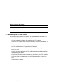
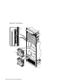
Opening the System Cabinet . . . . . . . . . . . . .
Removing the Top Cover and Side Panels
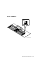
Removing the Card Cage Cover . . . . . . . .
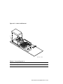
Removing the Bezels . . . . . . . . . . . . . . . .
.
.
.
.
.
.
.
.
.
.
.
.
.
.
.
.
.
.
.
.
.
.
.
.
.
.
.
.
.
.
.
.
.
.
.
.
.
.
.
.
.
.
.
.
.
.
.
.
.
.
.
.
.
.
.
.
.
.
.
.
.
.
.
.
.
.
.
.
.
.
.
.
.
.
.
.
.
.
.
.
.
.
.
.
.
.
.
.
.
.
.
.
.
.
.
.
.
.
.
.
.
.
.
.
.
.
.
.
.
.
.
.
.
.
.
.
.
.
.
.
4–1
4–3
4–3
4–4
4–5
4–5
4–5
4–7
4 FRU Removal and Replacement
4.1
4.2
4.3
4.4
4.5
4.5.1
4.5.2
4.5.3
iv
4.6
4.7
4.8
4.9
4.10
4.11
4.12
4.13
4.14
4.14.1
4.15
4.16
4.17
4.18
4.19
Replacing the CPU Module . . . . . . . . . . . . .
Replacing the Cache Card . . . . . . . . . . . . . .
Replacing a SIMM . . . . . . . . . . . . . . . . . . . .
Replacing the Memory Expansion Module . .
Replacing Option Modules . . . . . . . . . . . . . .
Replacing the System Board . . . . . . . . . . . .
Replacing the Real-Time Clock Chip . . . . . .
Replacing the RX23 3.5-Inch Diskette Drive
Replacing an Option Drive . . . . . . . . . . . . . .
Option Drive Installation Data . . . . . . .
Replacing the Speaker . . . . . . . . . . . . . . . . .
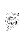
Replacing the Front Panel Wire Assembly . .
Replacing a Fan . . . . . . . . . . . . . . . . . . . . . .
Replacing the Power Supply . . . . . . . . . . . .
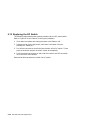
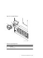
Replacing the DC Switch . . . . . . . . . . . . . . .
.
.
.
.
.
.
.
.
.
.
.
.
.
.
.
.
.
.
.
.
.
.
.
.
.
.
.
.
.
.
.
.
.
.
.
.
.
.
.
.
.
.
.
.
.
.
.
.
.
.
.
.
.
.
.
.
.
.
.
.
.
.
.
.
.
.
.
.
.
.
.
.
.
.
.
.
.
.
.
.
.
.
.
.
.
.
.
.
.
.
.
.
.
.
.
.
.
.
.
.
.
.
.
.
.
.
.
.
.
.
.
.
.
.
.
.
.
.
.
.
.
.
.
.
.
.
.
.
.
.
.
.
.
.
.
.
.
.
.
.
.
.
.
.
.
.
.
.
.
.
.
.
.
.
.
.
.
.
.
.
.
.
.
.
.
.
.
.
.
.
.
.
.
.
.
.
.
.
.
.
.
.
.
.
.
.
.
.
.
.
.
.
.
.
.
.
.
.
.
.
.
.
.
.
.
.
.
.
.
.
.
.
.
.
.
.
.
.
.
.
.
.
.
.
.
.
.
.
.
.
.
.
.
.
.
.
.
.
.
.
4–9
4–12
4–14
4–18
4–20
4–22
4–26
4–28
4–31
4–32
4–49
4–51
4–53
4–55
4–58
EISA Architecture . . . . . . . . . . . . . . . . . . . . . . . . . . . . . . . . . . . .
System Configuration Utility . . . . . . . . . . . . . . . . . . . . . . . . . . . .
Diskettes Provided . . . . . . . . . . . . . . . . . . . . . . . . . . . . . . . . .
When to Use the SCU . . . . . . . . . . . . . . . . . . . . . . . . . . . . . .
Booting the SCU . . . . . . . . . . . . . . . . . . . . . . . . . . . . . . . . . .
How to Use the SCU . . . . . . . . . . . . . . . . . . . . . . . . . . . . . . .
SCI Files and CFG Files . . . . . . . . . . . . . . . . . . . . . . . . . . . .
Configuring the Computer System . . . . . . . . . . . . . . . . . . . . . . . .
Access Password Utility . . . . . . . . . . . . . . . . . . . . . . . . . . . . .
Configure Computer . . . . . . . . . . . . . . . . . . . . . . . . . . . . . . . .
Important EISA Configuration Information . . . . . . . . . . . . . .
Adding or Removing Boards . . . . . . . . . . . . . . . . . . . . . . . . . .
View or Edit Details . . . . . . . . . . . . . . . . . . . . . . . . . . . . . . . .
System Board Extended Memory . . . . . . . . . . . . . . . . . . .
System Base Memory . . . . . . . . . . . . . . . . . . . . . . . . . . . .
Shadow Off-Board Video BIOS . . . . . . . . . . . . . . . . . . . . .
User Definable Hard Disk Drive . . . . . . . . . . . . . . . . . . .
Hard Drive 1 . . . . . . . . . . . . . . . . . . . . . . . . . . . . . . . . . .
Hard Drive 2 . . . . . . . . . . . . . . . . . . . . . . . . . . . . . . . . . .
Parallel Port and Serial Ports . . . . . . . . . . . . . . . . . . . . .
CPU Speed . . . . . . . . . . . . . . . . . . . . . . . . . . . . . . . . . . . .
Examine Required Switches . . . . . . . . . . . . . . . . . . . . . . . . . .
Save and Exit . . . . . . . . . . . . . . . . . . . . . . . . . . . . . . . . . . . . .
Configuring the System with the SCU for ISA Modules . . . . . . . .
Adding an ISA CFG File . . . . . . . . . . . . . . . . . . . . . . . . . . . .
5–1
5–1
5–2
5–3
5–3
5–6
5–6
5–7
5–9
5–10
5–10
5–10
5–11
5–16
5–16
5–16
5–16
5–17
5–17
5–17
5–17
5–17
5–18
5–18
5–18
5 System Configuration
5.1
5.2
5.2.1
5.2.2
5.2.3
5.2.4
5.2.5
5.3
5.3.1
5.3.2
5.3.3
5.3.4
5.3.5
5.3.5.1
5.3.5.2
5.3.5.3
5.3.5.4
5.3.5.5
5.3.5.6
5.3.5.7
5.3.5.8
5.3.6
5.3.7
5.4
5.4.1
v
5.5
5.6
5.7
5.8
5.9
5.9.1
Configuring the System with EISA Option Modules
Automatic Configuration . . . . . . . . . . . . . . . . . . . . .
Viewing Total System Configuration . . . . . . . . . . . .
Library Diskette . . . . . . . . . . . . . . . . . . . . . . . . . . . .
Advanced System Configuration Utility Feature . . .
Installing More than One Terminal Multiplexer
.
.
.
.
.
.
.
.
.
.
.
.
.
.
.
.
.
.
.
.
.
.
.
.
.
.
.
.
.
.
.
.
.
.
.
.
.
.
.
.
.
.
.
.
.
.
.
.
.
.
.
.
.
.
.
.
.
.
.
.
5–20
5–20
5–21
5–22
5–22
5–23
.
.
.
.
.
.
.
.
.
.
.
.
.
.
.
.
.
.
.
.
.
.
.
.
.
.
.
.
.
.
.
.
.
.
.
.
.
.
.
.
.
.
.
.
.
.
.
.
.
.
A–1
A–1
A–3
A–3
A–4
Introduction . . . . . . . . . . . . . . . . . . . . . . . . . . . . . . . . . . . . . . . . .
Jumper Settings . . . . . . . . . . . . . . . . . . . . . . . . . . . . . . . . . . . . . .
B–1
B–1
A System Specifications
A.1
A.2
A.3
A.4
A.5
Introduction . . . . . . . . . . . . . . . . . . . . . . . . . . .
System Specifications . . . . . . . . . . . . . . . . . . . .
Power Supply and Input Power Requirements .
Expansion Slot Current Limitations . . . . . . . .
System Component Current Requirements . . .
.
.
.
.
.
.
.
.
.
.
.
.
.
.
.
.
.
.
.
.
B System Board Jumpers
B.1
B.2
C Interface Connectors
C.1
C.2
C.2.1
C.2.2
C.2.3
Introduction . . . . . . . . . . . . . . . . . . .
External System Connectors . . . . . .
Parallel Printer Connector . . . . .
Serial Port Connectors . . . . . . . .
Keyboard and Mouse Connectors
D Device Mapping
E ISA Option Configuration Files
Index
vi
.
.
.
.
.
.
.
.
.
.
.
.
.
.
.
.
.
.
.
.
.
.
.
.
.
.
.
.
.
.
.
.
.
.
.
.
.
.
.
.
.
.
.
.
.
.
.
.
.
.
.
.
.
.
.
.
.
.
.
.
.
.
.
.
.
.
.
.
.
.
.
.
.
.
.
.
.
.
.
.
.
.
.
.
.
.
.
.
.
.
.
.
.
.
.
.
.
.
.
.
.
.
.
.
.
.
.
.
.
.
C–1
C–1
C–1
C–2
C–3
Figures
1–1
1–2
1–3
1–4
4–1
4–2
4–3
4–4
4–5
4–6
4–7
4–8
4–9
4–10
4–11
4–12
4–13
4–14
4–15
4–16
4–17
4–18
4–19
4–20
4–21
4–22
4–23
4–24
4–25
4–26
4–27
4–28
4–29
4–30
5–1
System Cabinet, Front View . . . . . . . . . . . . . . . . . .
System Cabinet, Rear View . . . . . . . . . . . . . . . . . . .
System Cabinet, Internal View . . . . . . . . . . . . . . . .
System Board . . . . . . . . . . . . . . . . . . . . . . . . . . . . . .
System Cover and Side Panel Removal . . . . . . . . . .
Bezel Removal . . . . . . . . . . . . . . . . . . . . . . . . . . . . .
CPU Module Removal . . . . . . . . . . . . . . . . . . . . . . .
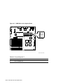
CPU Module Layout . . . . . . . . . . . . . . . . . . . . . . . . .
Cache Card Removal . . . . . . . . . . . . . . . . . . . . . . . .
SIMM Removal . . . . . . . . . . . . . . . . . . . . . . . . . . . .
SIMM Slots on the System Board . . . . . . . . . . . . . .
SIMM Slots on the Memory Module . . . . . . . . . . . . .
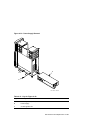
Memory Expansion Module Removal . . . . . . . . . . . .
Option Module Removal . . . . . . . . . . . . . . . . . . . . . .
System Board Removal . . . . . . . . . . . . . . . . . . . . . .
RX23 3.5-Inch Diskette Drive Removal (Part 1 of 2)
RX23 3.5-Inch Diskette Drive Removal (Part 2 of 2)
Option Drive Removal . . . . . . . . . . . . . . . . . . . . . . .
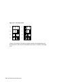
ID Jumper Code . . . . . . . . . . . . . . . . . . . . . . . . . . . .
TZK10-AA ID Jumper Locations . . . . . . . . . . . . . . .
RZ24-S Jumper Locations . . . . . . . . . . . . . . . . . . . .
RZ25-S Jumper Locations . . . . . . . . . . . . . . . . . . . .
RZ56-E/RZ57-E ID Jumper Locations . . . . . . . . . . .
RZ57-E ID and Configuration Jumpers Location . . .
RZ35-E Jumper Locations . . . . . . . . . . . . . . . . . . . .
RZ58-E Jumper Locations . . . . . . . . . . . . . . . . . . . .
105 MB IDE Drive Jumper Locations . . . . . . . . . . .
RX33-AS Jumper Locations . . . . . . . . . . . . . . . . . . .
Speaker Removal . . . . . . . . . . . . . . . . . . . . . . . . . . .
Front Panel Wire Assembly Removal . . . . . . . . . . . .
Fan Removal . . . . . . . . . . . . . . . . . . . . . . . . . . . . . .
Power Supply Cable Removal . . . . . . . . . . . . . . . . . .
Power Supply Removal . . . . . . . . . . . . . . . . . . . . . .
DC Switch Removal . . . . . . . . . . . . . . . . . . . . . . . . .
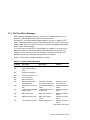
SCU Main Menu Options (Part 1 of 2) . . . . . . . . . . .
.
.
.
.
.
.
.
.
.
.
.
.
.
.
.
.
.
.
.
.
.
.
.
.
.
.
.
.
.
.
.
.
.
.
.
.
.
.
.
.
.
.
.
.
.
.
.
.
.
.
.
.
.
.
.
.
.
.
.
.
.
.
.
.
.
.
.
.
.
.
.
.
.
.
.
.
.
.
.
.
.
.
.
.
.
.
.
.
.
.
.
.
.
.
.
.
.
.
.
.
.
.
.
.
.
.
.
.
.
.
.
.
.
.
.
.
.
.
.
.
.
.
.
.
.
.
.
.
.
.
.
.
.
.
.
.
.
.
.
.
.
.
.
.
.
.
.
.
.
.
.
.
.
.
.
.
.
.
.
.
.
.
.
.
.
.
.
.
.
.
.
.
.
.
.
.
.
.
.
.
.
.
.
.
.
.
.
.
.
.
.
.
.
.
.
.
.
.
.
.
.
.
.
.
.
.
.
.
.
.
.
.
.
.
.
.
.
.
.
.
.
.
.
.
.
.
.
.
.
.
.
.
.
.
.
.
.
.
.
.
.
.
.
.
.
1–3
1–5
1–7
1–11
4–6
4–8
4–10
4–11
4–13
4–15
4–16
4–17
4–19
4–21
4–24
4–29
4–30
4–32
4–34
4–35
4–36
4–38
4–40
4–41
4–42
4–44
4–46
4–48
4–50
4–52
4–54
4–56
4–57
4–59
5–4
vii
5–2
B–1
SCU Main Menu Options (Part 2 of 2) . . . . . . . . . . . . . . . . . .
Location of System Board Jumpers . . . . . . . . . . . . . . . . . . . .
5–5
B–2
Tables
1
1–1
1–2
1–3
1–4
2–1
2–2
2–3
2–4
2–5
2–6
2–7
2–8
3–1
3–2
3–3
3–4
3–5
3–6
3–7
3–8
3–9
3–10
3–11
3–12
3–13
3–14
3–15
3–16
3–17
4–1
4–2
viii
applicationDEC 400xP Documentation Set . .
Key for Figure 1–1 . . . . . . . . . . . . . . . . . . . . .
Key for Figure 1–2 . . . . . . . . . . . . . . . . . . . . .
Key for Figure 1–3 . . . . . . . . . . . . . . . . . . . . .
Key for Figure 1–4 . . . . . . . . . . . . . . . . . . . . .
Diagnostic Tools . . . . . . . . . . . . . . . . . . . . . . .
POST and Boot Messages . . . . . . . . . . . . . . .
Beep Codes for Fatal Errors . . . . . . . . . . . . . .
Beep Codes for Nonfatal Errors . . . . . . . . . . .
Run-Time Error Messages . . . . . . . . . . . . . . .
System Troubleshooting . . . . . . . . . . . . . . . . .
Disk Drive Troubleshooting . . . . . . . . . . . . . .
Monitor Troubleshooting . . . . . . . . . . . . . . . .
System Exerciser Tests . . . . . . . . . . . . . . . . .
System Exerciser Modes . . . . . . . . . . . . . . . .
System Exerciser Flags . . . . . . . . . . . . . . . . .
System Exerciser Commands . . . . . . . . . . . . .
Block Command Options . . . . . . . . . . . . . . . .
Calculate Command Qualifiers . . . . . . . . . . .
Calculate Command Radix Symbols . . . . . . . .
Devices Command Formats . . . . . . . . . . . . . .
Devices Command State Flags . . . . . . . . . . . .
Display Command Qualifiers . . . . . . . . . . . . .
Examine Command Qualifiers . . . . . . . . . . . .
Log Command Options . . . . . . . . . . . . . . . . . .
System Exerciser Error Log Report, Example
Set Command State Variables . . . . . . . . . . . .
Show Command Machine States . . . . . . . . . .
Status Command Options . . . . . . . . . . . . . . .
Unblock Command Options . . . . . . . . . . . . . .
Field Replaceable Units . . . . . . . . . . . . . . . . .
Key for Figure 4–1 . . . . . . . . . . . . . . . . . . . . .
.
.
.
.
.
.
.
.
.
.
.
.
.
.
.
.
.
.
.
.
.
.
.
.
.
.
.
.
.
.
.
.
.
.
.
.
.
.
.
.
.
.
.
.
.
.
.
.
.
.
.
.
.
.
.
.
.
.
.
.
.
.
.
.
.
.
.
.
.
.
.
.
.
.
.
.
.
.
.
.
.
.
.
.
.
.
.
.
.
.
.
.
.
.
.
.
.
.
.
.
.
.
.
.
.
.
.
.
.
.
.
.
.
.
.
.
.
.
.
.
.
.
.
.
.
.
.
.
.
.
.
.
.
.
.
.
.
.
.
.
.
.
.
.
.
.
.
.
.
.
.
.
.
.
.
.
.
.
.
.
.
.
.
.
.
.
.
.
.
.
.
.
.
.
.
.
.
.
.
.
.
.
.
.
.
.
.
.
.
.
.
.
.
.
.
.
.
.
.
.
.
.
.
.
.
.
.
.
.
.
.
.
.
.
.
.
.
.
.
.
.
.
.
.
.
.
.
.
.
.
.
.
.
.
.
.
.
.
.
.
.
.
.
.
.
.
.
.
.
.
.
.
.
.
.
.
.
.
.
.
.
.
.
.
.
.
.
.
.
.
.
.
.
.
.
.
.
.
.
.
.
.
.
.
.
.
.
.
.
.
.
.
.
.
.
.
.
.
.
.
.
.
.
.
.
.
.
.
.
.
.
.
.
.
.
.
.
.
.
.
.
.
.
.
.
.
.
.
.
.
.
.
.
.
.
.
.
.
.
.
.
.
.
.
.
.
.
.
.
.
.
.
.
.
.
.
.
.
.
.
.
.
.
.
.
.
.
.
.
.
.
.
.
.
.
.
.
.
.
.
.
.
.
.
xii
1–2
1–4
1–6
1–10
2–1
2–5
2–16
2–18
2–19
2–20
2–23
2–24
3–8
3–8
3–9
3–10
3–11
3–13
3–13
3–15
3–16
3–17
3–18
3–20
3–20
3–23
3–24
3–25
3–25
4–1
4–7
4–3
4–4
4–5
4–6
4–7
4–8
4–9
4–10
4–11
4–12
4–13
4–14
4–15
4–16
4–17
4–18
4–19
4–20
4–21
4–22
4–23
4–24
4–25
4–26
4–27
4–28
4–29
4–30
4–31
4–32
5–1
5–2
5–3
A–1
A–2
A–3
Key for Figure 4–2 . . . . . . . . . . . . . . . . . . . . . . . . . . . . . . .
Key for Figure 4–3 . . . . . . . . . . . . . . . . . . . . . . . . . . . . . . .
Key for Figure 4–4 . . . . . . . . . . . . . . . . . . . . . . . . . . . . . . .
Cache Size Jumper . . . . . . . . . . . . . . . . . . . . . . . . . . . . . . .
Key for Figure 4–5 . . . . . . . . . . . . . . . . . . . . . . . . . . . . . . .
Key for Figure 4–7 . . . . . . . . . . . . . . . . . . . . . . . . . . . . . . .
Key for Figure 4–8 . . . . . . . . . . . . . . . . . . . . . . . . . . . . . . .
Memory Expansion Module Jumpers . . . . . . . . . . . . . . . . .
Key for Figure 4–9 . . . . . . . . . . . . . . . . . . . . . . . . . . . . . . .
Key for Figure 4–10 . . . . . . . . . . . . . . . . . . . . . . . . . . . . . .
Key for Figure 4–11 . . . . . . . . . . . . . . . . . . . . . . . . . . . . . .
Key for Figure 4–12 . . . . . . . . . . . . . . . . . . . . . . . . . . . . . .
Key for Figure 4–13 . . . . . . . . . . . . . . . . . . . . . . . . . . . . . .
Key for Figure 4–14 . . . . . . . . . . . . . . . . . . . . . . . . . . . . . .
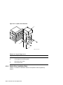
Bay Option Installation Data . . . . . . . . . . . . . . . . . . . . . . .
Key for Figure 4–16 . . . . . . . . . . . . . . . . . . . . . . . . . . . . . .
Key for Figure 4–17 . . . . . . . . . . . . . . . . . . . . . . . . . . . . . .
Key for Figure 4–18 . . . . . . . . . . . . . . . . . . . . . . . . . . . . . .
Key for Figure 4–19 . . . . . . . . . . . . . . . . . . . . . . . . . . . . . .
Key for Figure 4–20 . . . . . . . . . . . . . . . . . . . . . . . . . . . . . .
Key for Figure 4–21 . . . . . . . . . . . . . . . . . . . . . . . . . . . . . .
Key for Figure 4–22 . . . . . . . . . . . . . . . . . . . . . . . . . . . . . .
Key for Figure 4–23 . . . . . . . . . . . . . . . . . . . . . . . . . . . . . .
Key for Figure 4–24 . . . . . . . . . . . . . . . . . . . . . . . . . . . . . .
Key for Figure 4–25 . . . . . . . . . . . . . . . . . . . . . . . . . . . . . .
Key for Figure 4–26 . . . . . . . . . . . . . . . . . . . . . . . . . . . . . .
Key for Figure 4–27 . . . . . . . . . . . . . . . . . . . . . . . . . . . . . .
Key for Figure 4–28 . . . . . . . . . . . . . . . . . . . . . . . . . . . . . .
Key for Figure 4–29 . . . . . . . . . . . . . . . . . . . . . . . . . . . . . .
Key for Figure 4–30 . . . . . . . . . . . . . . . . . . . . . . . . . . . . . .
SCU Keyboard Function Keys . . . . . . . . . . . . . . . . . . . . . .
System Board Setup Options . . . . . . . . . . . . . . . . . . . . . . .
ISA CFG Files for applicationDEC 400xP ISA Modules . . .
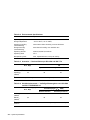
System Dimensions . . . . . . . . . . . . . . . . . . . . . . . . . . . . . .
Environmental Specifications . . . . . . . . . . . . . . . . . . . . . . .
Acoustics — Declared Values per ISO 9296 and ISO 7779 .
.
.
.
.
.
.
.
.
.
.
.
.
.
.
.
.
.
.
.
.
.
.
.
.
.
.
.
.
.
.
.
.
.
.
.
.
.
.
.
.
.
.
.
.
.
.
.
.
.
.
.
.
.
.
.
.
.
.
.
.
.
.
.
.
.
.
.
.
.
.
.
.
4–8
4–10
4–11
4–12
4–13
4–16
4–17
4–18
4–19
4–21
4–25
4–29
4–31
4–32
4–33
4–35
4–37
4–39
4–40
4–41
4–43
4–45
4–47
4–49
4–51
4–53
4–55
4–56
4–57
4–59
5–6
5–11
5–19
A–1
A–2
A–2
ix
A–4
A–5
A–6
B–1
C–1
C–2
C–3
D–1
D–2
D–3
D–4
D–5
E–1
x
Schallemissionswerte — Vorläufige Werteangaben nach ISO
9296 und ISO 7779/DIN45635-19 . . . . . . . . . . . . . . . . . . . . . .
System Power Requirements . . . . . . . . . . . . . . . . . . . . . . . . .
Computer Component Current and Power Requirements . . .
System Board Jumper Settings . . . . . . . . . . . . . . . . . . . . . . .
Parallel Printer Connector Pinout . . . . . . . . . . . . . . . . . . . . .
Serial Port Connector Pinout . . . . . . . . . . . . . . . . . . . . . . . . .
Keyboard and Mouse Connector Pinouts . . . . . . . . . . . . . . . .
Memory Map, Without Options . . . . . . . . . . . . . . . . . . . . . . .
Memory Map, Typical Configuration . . . . . . . . . . . . . . . . . . .
I/O Address Map . . . . . . . . . . . . . . . . . . . . . . . . . . . . . . . . . .
Interrupt Map . . . . . . . . . . . . . . . . . . . . . . . . . . . . . . . . . . . .
DMA Map . . . . . . . . . . . . . . . . . . . . . . . . . . . . . . . . . . . . . . .
ISA Option Configuration Files . . . . . . . . . . . . . . . . . . . . . . .
A–2
A–3
A–4
B–3
C–2
C–3
C–3
D–1
D–2
D–2
D–4
D–5
E–1
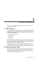
Preface
Intended Audience
This manual is intended for service technicians trained by Digital Equipment
Corporation.
Purpose
This manual is designed to help service technicians diagnose and repair
the applicationDEC 400xP system. It contains service information for the
base system and for options supplied by Digital Equipment Corporation. For
information on configuration and installation of options supplied by Digital,
refer to the applicationDEC 400xP User Guide.
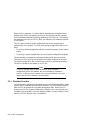
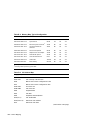
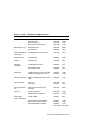
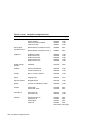
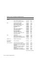
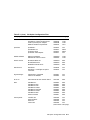
applicationDEC 400xP Documentation Set
This manual is part of a documentation set shipped with each applicationDEC 400xP
system. The manuals in this set are listed in Table 1.
xi
Table 1 applicationDEC 400xP Documentation Set
Manual
Part Number
System Installation Guide
1
EK-PS200-IG
Minimum Requirements for Operating Systems
1
1
EK-PS200-AD
Electrostatic Discharge Notice
EK-PS200-ED
1
EK-PS200-CC
Product Information Request
Software Support Notice1
EK-PS100-SW
User Guide
EK-PS200-CG
SCO UNIX Boot Process Notice
1
1
EK-PS200-SB
Part of the applicationDEC 400xP Installation Package (EK-PS200-IP)
Conventions
The following conventions are used in this manual:
Enter
A key name, such as Enter, is shown enclosed to indicate that you
press a key on the keyboard.
Ctrl/X
A two key sequence, such as Ctrl/X, is shown enclosed to
indicate that you must hold down the key labeled Ctrl while you
simultaneously press another key.
Ctrl/Alt/Delete
A multiple key sequence, such as Ctrl/Alt/Delete, is shown enclosed
to indicate that you must hold down the keys labeled Ctrl and Alt
while you simultaneously press another key.
boldface text
Boldface text is used to represent the name of a command.
italic text
Italic text is used to indicate SCO UNIX System V file names.
Notes, Cautions, and Warnings are used throughout this manual to emphasize
specific kinds of information:
Warning
A Warning indicates the presence of a hazard that can cause personal
injury.
xii
Caution
A Caution indicates the presence of a hazard that might damage the
hardware or currupt the software.
Note
A Note indicates important or explanatory information.
xiii
1
System Overview
The applicationDEC 400xP system is a versatile, industry standard computer
system suitable for use in any of the following configurations:
•
Multiuser timesharing configurations running SCO UNIX System V
•
Network file server for Digital PATHWORKS, Novell NetWare, or Banyan
Vines network operating systems
•
Single user workstation environments running MS–DOS or Open Desktop
1.1 Features
The applicationDEC 400xP system features include:
•
Intel 80486 CPU speeds of 25, 33, or 50 MHz
•
Up to 256 KB of cache memory
•
Up to 192 MB of system memory
•
Support for 2, 4, 8, and 16 MB single in-line memory modules (SIMMs)
•
Support for IDE and SCSI hard disks
•
Up to 4.8 GB of internal SCSI disk storage
•
Up to 14 GB of additional external disk storage
•
Universal 350 W power supply
•
1.44 MB 3.5-inch diskette drive standard
•
Seven half-height storage bays, convertible to three full-height and one
half-height bay
System Overview 1–1
The applicationDEC 400xP system supports:
•
SCO UNIX System V
•
Open Desktop
•
All industry standard SCO UNIX System V applications
•
MS–DOS
•
Banyan Vines
•
Novell NetWare
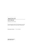
1.2 System Cabinet
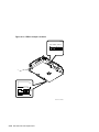
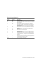
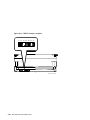
The system cabinet front panel is shown in Figure 1–1. Refer to the figure key
in Table 1–1.
Table 1–1 Key for Figure 1–1
Key
Description
A
Disk activity LED — indicates activity on the IDE and SCSI bus
B
Keyboard lock — disables system keyboard and mouse
C
Reset button — resets the system by emulating a power-off/power-on
sequence and causes POST to run
D
1.44 MB, 3.5-inch diskette drive
E
1.2 MB, 5.25-inch diskette drive (optional)
F
525 MB QIC tape drive (optional)
G
Blank panel
H
Power indicator — indicates power is applied to the system
I
Power switch (Standby/On) — applies power to the system
J
Support feet
K
Cabinet rear wheels
L
Diskette eject button
1–2 System Overview
Figure 1–1 System Cabinet, Front View
B
C
D
E
F
A
G
L
H
K
J
I
MR-0038-92DG
System Overview 1–3
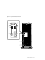
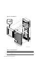
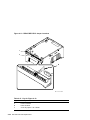
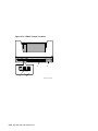
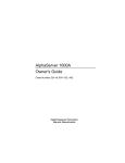
1.2.1 Rear Connectors
The system cabinet rear panel connectors are shown in Figure 1–2. Refer
to the figure key in Table 1–2. For more information about the rear panel
connectors, refer to Appendix C.
Table 1–2 Key for Figure 1–2
Key
Description
A
Cabinet keylock
B
Mouse connector — connects mouse used with VGA analog monitor
C
Keyboard connector — connects keyboard used with VGA analog
monitor
D
Serial port 1 — RS-232 port for serial printers, UPS control, configured
as COM1
E
Serial port 2 — RS-232 port for serial printers, UPS control, configured
as COM2
F
Parallel port — parallel printer port, configured as LPT1
G
VGA monitor connector — connects VGA analog monitor
H
Option module external connector slots (8)
I
Auxiliary ac output — unswitched IEC-320 connector
J
AC input
1–4 System Overview
Figure 1–2 System Cabinet, Rear View
A
B
C
1
1
D
E
G
F
1
H
I
J
MR-0039-92DG
System Overview 1–5
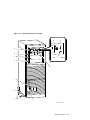
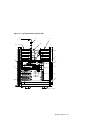
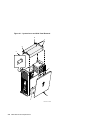
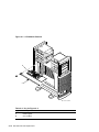
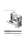
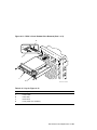
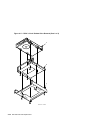
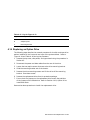
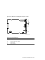
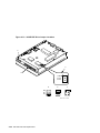
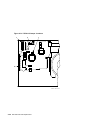
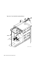
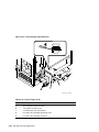
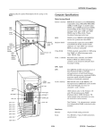
1.2.2 Internal Layout
Figure 1–3 shows the internal layout of the system when the cabinet is opened.
Refer to the figure key in Table 1–3.
Table 1–3 Key for Figure 1–3
Key
Description
A
SCSI bus cable
B
Power cables
C
Front drive bays
D
SCSI terminator
E
Rear drive bays
F
Diskette drive cable
G
System board
H
CPU module
I
On-board memory SIMMs
J
Memory expansion module
K
Power supply
L
I/O connectors
M
SCSI host adapter
N
EISA option module slots (8)
1–6 System Overview
Figure 1–3 System Cabinet, Internal View
D
E
A
C
B
F
G
L
H
I
M
J
K
N
MR-0565-91DG
System Overview 1–7
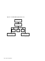
1.3 System Logic
The applicationDEC 400xP system consists of three logic modules (see
Figure 1–3):
•
System board
•
CPU module with optional plug-in cache (25 MHz and 33 MHz CPU) or
attached cache (50 MHz CPU)
•
Optional memory expansion module
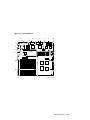
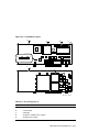
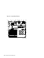
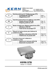
1.3.1 System Board
The system board, shown in Figure 1–4, contains the following features:
•
Slot for CPU module
•
Slot for memory expansion module
•
8 EISA slots (6 bus master slots, 2 slave slots)
•
On-board VGA with 512K RAM (optional upgrade to 1 MB RAM) and 1024
x 768 resolution
•
4 SIMM sockets (accepts 2, 4, 8, and 16 MB SIMMs for maximum of 64
MB)
•
Diskette drive control
•
IDE drive control
•
2 9-pin serial ports
•
1 25-pin parallel port
•
Keyboard and mouse connections
•
VGA monitor connection
Refer to the figure key in Table 1–4.
1–8 System Overview
1.3.1.1 Option Module Slots
Eight extended industry standard architecture (EISA) option slots are available
on the system board. The slots are industry standard architecture (ISA)
compatible, so both EISA and ISA option modules can be installed.
Six of the EISA slots are EISA master slots. EISA master modules must
be installed in EISA master slots. EISA master modules are devices which
assume control of the bus for activities such as direct memory access (DMA).
ISA modules and EISA slave modules may be installed in any slot.
Note
When you replace the system board, always install the modules in the
same slots from which they were removed.
1.3.1.2 System Board Jumpers
System board jumpers allow you to set certain system options. For more
information, refer to Appendix B.
1.3.1.3 Real-Time Clock Chip
The real-time clock chip, which contains a lithium battery, provides power for
nonvolatile memory when power is removed from the system.
1.3.2 CPU Module
The CPU and all associated speed-dependent components are isolated on a
separate CPU module. Upgrading a system is as easy as removing the current
CPU module and replacing it with a faster CPU module. The system can be
configured for use with the following Intel 80486 CPU modules.
•
25 MHz Intel 486SX
•
33 MHz Intel 486DX
•
50 MHz Intel 486DX
The 25 MHz and 33 MHz CPU modules contain a socket for installation of an
optional 64 or 128 KB cache card. The 50 MHz CPU module comes standard
with 256 KB cache installed.
System Overview 1–9
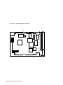
Table 1–4 Key for Figure 1–4
Key
Description
A
Memory bank 0
B
Memory bank 1
C
Install first SIMM here
D
Pin 1 of SIMM socket
E
CPU module slot
F
Memory module slot
G
System setup jumpers1
H
SCSI/IDE disk drive activity LED cable connectors2
J
VGA setup jumpers1
K
IDE cable connector
L
VGA 512K memory upgrade sockets
M
Power connector (cable from power supply is factory installed)
N
Diskette cable connector (cable is factory installed)
O
Real-time clock
P
Western Digital WD90C30 VGA chip
Q
EISA slave slots
R
EISA master slots
S
Front panel connector (cable is factory installed)
1
Table B–1 lists the system board jumpers and factory default settings.
2
On some system boards, J0190 and/or J0491 may not be populated.
1–10 System Overview
Figure 1–4 System Board
K
L
M
M
E
E
S
N
J
C
E
P
B
F
A
H
Q
O
G
R
H
D
MR-0033-92DG
System Overview 1–11
1.3.3 Memory Expansion Module
The memory expansion module:
•
Allows for increased memory beyond the 64 MB of memory that can be
installed on the system board
•
Is installed in a slot on the system board
•
Contains 8 SIMM slots
•
Accepts 2, 4, 8, and 16 MB SIMMs
If 16 MB SIMMs are installed on the memory expansion module, an additional
128 MB of memory is provided. Combined with the maximum possible 64 MB
available on the system board, 192 MB of memory is available.
All of the memory logic is designed for future support of 32 MB SIMMs. When
32 MB SIMMs are available, the total possible memory will be 384 MB.
1.4 Power Supply
In the lower area of the cabinet is the system power supply. The supply
provides 350 W to the system cabinet and autosenses input power. This means
the cabinet can be connected to 110/120 V or 220/240 V, 50 or 60 Hz, without
making any mechanical settings.
1.5 Disk Storage and Media Options
The system board supports IDE drives directly. An IDE drive connector on the
board allows connection of up to two 105 MB half-height IDE drives.
By installing a SCSI adapter in an EISA expansion slot, greater expansion is
possible. A SCSI bus can have up to seven SCSI devices. The system enclosure
has seven half-height expansion bays. These are convertible to full-height
bays. Any combination of full- and half-height bays is possible. For maximum
storage, three 1.3 GB full-height SCSI drives and one 852 MB half-height drive
can be installed for a total of 4.8 GB inside the enclosure.
Three of the seven half-height storage bays are accessible. These bays are
directly below the standard 3.5-inch 1.44 MB diskette drive in the front of the
enclosure. These bays can be used for the installation of SCSI half-height or
full-height tape drives, if desired.
1–12 System Overview
1.6 Keyboard
There are no service procedures for the keyboard other than replacement.
1.7 Mouse
Service procedures for the mouse are limited to cleaning the mouse ball and
tracking mechanism. Refer to the documentation supplied with the mouse.
System Overview 1–13
2
System Troubleshooting
2.1 Introduction
This chapter describes troubleshooting of the applicationDEC 400xP system. It
contains the following sections:
•
Diagnostic tools
•
Power-on self-test
•
Setup utility
•
Run-time error messages
•
Troubleshooting
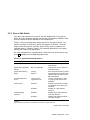
2.2 Diagnostic Tools
Table 2–1 lists the diagnostic tools required to service the applicationDEC 400xP
system.
Table 2–1 Diagnostic Tools
Tool
Part Number
Description
System Configuration Utility
Diskette (APPLICATIONDEC
400 XP SYS 2.0)
AK-PNHPA-CA
This utility is used to
reconfigure the system when
options are installed.
Library Diskette (LIBRARY
DISK OF ISA CFG FILES)
AK-PLADB-CA
Library of ISA configuration
files used to reconfigure the
system when ISA options are
installed.
applicationDEC System
Exerciser diagnostics diskette
(APPLICATIONDEC SYSX 4.0)
AK-PGF7D-CA
Standalone system diagnostic
diskette. (See Chapter 3).
Loopback, 9-pin serial port
FD-10164-00
External loopback test
connector.
System Troubleshooting 2–1
2.3 Power-On Self-Test
Before the applicationDEC 400xP system can be used, all components must be
initialized and tested, and the operating system must be loaded into memory.
The BIOS that is stored in ROM controls this sequence of actions. A portion
of the BIOS contains a power-on self-test (POST). POST is responsible for
initializing and testing system components each time power is applied or when
the system boots. The remainder of the BIOS loads the operating system and
specific applications.
Each time you turn on the system, POST displays a numeric countdown (880
to 000) sequence as it tests the system board, Intel 486, system board timers
and logic devices, keyboard, memory, and so on. POST countdown numbers
800 through 520 are not displayed on the monitor, but are represented as beep
codes (see Section 2.3.5).
The power-on self-tests are divided into two types of tests: system board
hardware and peripheral hardware. The following sections describe these tests
as well as the POST sequence and POST messages.
2.3.1 System Board Hardware Tests
Post checks the system board hardware first. If any of these tests fails, a fatal
error condition exists and further testing and initialization is not possible.
You are notified that an error condition exists by an error message displayed
on the monitor or by beeps from the system speaker. Refer to Section 2.3.4
for descriptions of the POST messages and Section 2.3.5 for more on the beep
codes. The following list of the system hardware tests shows the order of
execution:
CPU
ROM BIOS (checksum)
Programmable interrupt timer (PIT)
Base 64 KB DRAM
CMOS RAM
EISA devices
DMA controller
Programmable interrupt controller (PIC)
Video controller
Keyboard controller
Real-time clock
2–2 System Troubleshooting
2.3.2 Peripheral Hardware Tests
The first peripheral hardware test procedure verifies that the system
configuration data stored in CMOS RAM matches the hardware present.
Then, the procedures continue to test and initialize other peripheral hardware.
This testing includes memory on the system board and, if one is installed, the
memory module. A test failure generally results in an error message on the
monitor screen. The following list of the peripheral hardware tests shows the
order of execution:
ISA CMOS RAM and EISA nonvolatile (FLASH) memory configuration
data
Serial/parallel interface circuitry
Video
Keyboard
RAM memory above 64 KB
Coprocessor
Diskette drive controller
Hard disk controller
Option ROMs, such as SCSI and LAN
Intel 486 CPU internal cache memory
2.3.3 POST Sequence
While POST is running, a numeric countdown (800 to 000) is displayed on the
monitor.
Note
During the POST memory test, the amount of memory being tested is
displayed on the screen. Depending on the amount of extended memory
installed, the POST memory test can take several minutes to complete.
POST does not check memory after a soft boot.
The POST message displayed may take one of two forms, depending on
whether POST detected any configuration errors. Examples follow.
System Troubleshooting 2–3
If POST does not detect any configuration errors, the system beeps once and
displays a message similar to the following:
PhoenixBIOS (TM) E486 Version x.xx.xx.xxx
Copyright (c) 1985-1991 Phoenix Technologies Ltd.
All Rights Reserved
. . .
640K Base Memory
03072K Extended
000
To continue press:.................................SPACEBAR
To configure system press:...............................F1
Note
After the above message appears, you have approximately 10 seconds
to press the appropriate function key to display the initial setup screen.
If you do not press the appropriate function key within the specified
time, and if POST failed to detect any configuration errors, the system
will continue with the boot sequence.
If configuration errors are found, the system beeps more than once and displays
a message similar to the following:
PhoenixBIOS (TM) E486 Version x.xx.xx.xxx
Copyright (c) 1985-1991 Phoenix Technologies Ltd.
All Rights Reserved
. . .
640K Base Memory
03072K Extended
150: Invalid configuration information
To continue press:......................................Esc
To configure system press:...............................F1
It is normal for the above message to appear the first time you start the
system. Run the system configuration utility (SCU) to create a valid system
configuration. If any other error messages appear on the screen, refer to
Section 2.3.4 for decriptions and solutions.
2–4 System Troubleshooting
2.3.4 POST and Boot Messages
POST displays messages to alert you to errors in hardware, software, and
firmware. It also displays information about your system.
During POST, the system board speaker beeps to alert you to specific POST
steps. Two beeps signal the start of the time during which you can enter setup.
Another beep signals the end of that time, and then a subsequent beep signals
that a system boot has begun.
If an error occurs during POST, the countdown is stopped. If an error occurs
before the monitor is initialized, specific beep codes sound to alert you to a
problem. If an error occurs after the monitor is initialized, both the POST
number and the error message are displayed on the monitor.
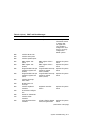
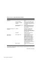
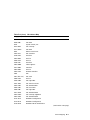
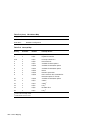
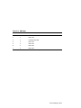
Table 2–2 lists POST and boot messages by number.
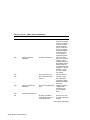
Table 2–2 POST and Boot Messages
POST No.
Error Name
Description
Solution
880
POST starts
860
Set processor speed for
POST
850
Chipset initialization 2
840
Chipset initialization 3
830
CPU register test
820
8742 initialization
810
Real-time clock RAM
and register test
Real-time clock RAM
and register test failure
Replace the realtime clock chip.
800
System BIOS checksum
test
System BIOS checksum
failure
Replace the system
board.
790
Initialize programmable
interval timer
Programmable interval
timer failure
Replace the system
board.
780
DMA channel test
DMA channel failure
Replace the system
board.
770
DMA page register test
DMA page register
failure
Replace the system
board.
760
Verify RAM refresh test
RAM refresh failure
Replace the system
board.
(continued on next page)
System Troubleshooting 2–5
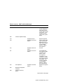
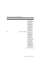
Table 2–2 (Cont.) POST and Boot Messages
POST No.
Error Name
Description
Solution
759
First 64 KB RAM parity
test failure
Memory has failed.
Run SYSEX.
Replace any failed
SIMM.
758
First 64 KB RAM
address line failure
Memory has failed.
Run SYSEX.
Replace any failed
SIMM.
757
First 64 KB RAM
odd/even logic failure
Memory has failed.
Run SYSEX.
Replace any failed
SIMM.
756
First 64 KB RAM chip
or data line failure,
multibit
Memory has failed.
Run SYSEX.
Replace any failed
SIMM.
755–740
First 64 KB RAM chip
or data line failure, bit
0–15
Memory has failed.
Run SYSEX.
Replace any failed
SIMM.
Shadow of on-board
BIOS failed
Memory has failed.
Run SYSEX.
Replace any failed
SIMM.
692
Extended CMOS
checksum failure
See 690.
691
CMOS checksum failure
730
Initialize stack
710
Initialize keyboard
buffer
700
Chipset initialization 4
See 690.
(continued on next page)
2–6 System Troubleshooting
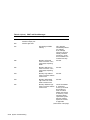
Table 2–2 (Cont.) POST and Boot Messages
POST No.
Error Name
Description
Solution
690
CMOS checksum test
CMOS power failure
The configuration
information stored
in CMOS does
not agree with
your hardware
configuration. Run
the SCU to verify
configuration.
Reboot system.
680
Initialize EISA slots
670
Initialize serial ports
660
Initialize parallel ports
655
DMA register test
(slave)
DMA register failure
(slave)
Replace the system
board.
650
DMA register test
(master)
DMA register failure
(master)
Replace the system
board.
645
Programmable interrupt
controller register test
(master)
Programmable interrupt
controller register
failure (master)
Replace the system
board.
640
Programmable interrupt
controller register test
(slave)
Programmable interrupt
controller register
failure (slave)
Replace the system
board.
620
Initialize interrupt
vector table
610
Enable timer tick
interrupt
600
Initialize keyboard
controller
Keyboard controller
failure
Replace the system
board.
590
Check video configuration
580
Search for video ROM
570
Initialize video
controller
560
Using alternate video
controller
Primary display adapter
failed, using alternate
Replace the system
board.
(continued on next page)
System Troubleshooting 2–7
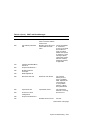
Table 2–2 (Cont.) POST and Boot Messages
POST No.
Error Name
Description
Solution
540
Scan and initialize video
ROM
530
Verify video configuration
520
Initialize console
redirection
500
Display sign on message
490
Timer tick interrupt test
No timer tick interrupt
Replace the system
board.
480
Shutdown test
Shutdown failure
Replace the system
board.
Software port NMI
failure
Replace the system
board.
Fail safe timer NMI
failure
Replace the system
board.
Unexpected interrupt in
protected mode
The computer
received an
interrupt while
in protected mode
(probably while
testing memory).
If the problem
persists, replace
the system board.
Gate A20 failure
The computer
cannot switch into
protected mode.
Replace the system
board.
461
460
EISA extended devices
test
450
Chipset initialization 6
441
440
Size memory above 64
KB
(continued on next page)
2–8 System Troubleshooting
Table 2–2 (Cont.) POST and Boot Messages
POST No.
Error Name
Description
Solution
430
Interval timer 2 test
Timer 2 failure
The integrated
system peripheral
(ISP) chip on the
system board might
have failed. If the
problem persists,
replace the system
board.
390
Initialize keyboard flags
374
Keyboard failure
Replace keyboard.
373
Keyboard stuck key
failure
One or more of the
keys was pressed.
Release the key or
keys and try again.
If the problem
persists, replace
the keyboard.
372
Keyboard data line
failure
See 371.
371
Keyboard clock line
failure
The keyboard or
the keyboard cable
connection has
failed. Check
the keyboard
connection. If the
connection is good,
the keyboard might
have failed. Try
another keyboard.
If the problem
persists, replace
the system board.
Keyboard controller
failure
Replace the system
board.
370
Test keyboard
350
Reinitialize keyboard
controller
330
Initialize auxiliary
device
(continued on next page)
System Troubleshooting 2–9
Table 2–2 (Cont.) POST and Boot Messages
POST No.
Error Name
Description
Solution
310
Initialize keyboard
controller output port
300
Initialize gate A20
297
Decreasing available
memory
This message
immediately follows
any memory
error message
informing you that
memory modules
are failing. Check
that all SIMMs are
installed correctly.
296
Memory write/read
failure at XXXX–YYYY,
read QQQQ expecting
ZZZZ
See 292.
295
Memory address line
failure at XXXX–YYYY,
read QQQQ expecting
ZZZZ
See 292.
294
Memory high address
failure at XXXX–0000 to
XXXX–FFFF
See 292.
293
Memory double word
logic failure at XXXX–
0000 to XXXX–FFFF
See 292.
292
Memory odd/even logic
failure at XXXX–0000 to
XXXX–FFFF
One of the SIMMs
or associated
circuitry has failed.
Run SYSEX to
check for failed
SIMM and replace
if necessary. If the
message repeats,
replace the system
board or memory
expansion module,
if applicable.
(continued on next page)
2–10 System Troubleshooting
Table 2–2 (Cont.) POST and Boot Messages
POST No.
Error Name
291
Description
Solution
Memory data line
failure at XXXX–0000 to
XXXX–FFFF
See 290.
Memory parity failure at
XXXX–0000 to XXXX–
FFFF
One of the SIMMs
or associated
circuitry has failed.
Run SYSEX to
check for failed
SIMM and replace
if necessary. If the
message repeats,
replace the system
board or memory
expansion module,
if applicable.
290
Test memory above 64
KB
270
Initialize extended BIOS
data area
250
Chipset initialization 7
230
Enable hardware
interrupts
210
Read keyboard ID
190
Real-time clock test
Real-time clock failure
The internal
battery for the
clock is probably
dead. Replace the
real-time clock.
If the problem
persists, replace
the system board.
160
Coprocessor test
Coprocessor failed
The coprocessor
failed or is missing.
150
Check for invalid
configuration
140
Chipset initialization 8
132
Run the SCU.
Diskette drive 1 failure
See 131.
(continued on next page)
System Troubleshooting 2–11
Table 2–2 (Cont.) POST and Boot Messages
POST No.
Error Name
Description
Solution
Diskette drive 0 failure
Drive 0 has either
failed or is missing.
Verify the settings
for drive 0 using
the BIOS Setup
Utility. Make sure
drive 0 is present
and the diskette is
inserted properly.
If it is, drive 0
might have failed.
Diskette drive failure
Drive has either
failed or is missing.
Verify the drive
settings using the
BIOS Setup Utility.
Make sure drive
is present and the
diskette is inserted
properly. If they
are, drive might
have failed.
122
Hard drive 0 failure
See 120 and 121.
121
Hard drive controller
failure
See 120. Check
both ends of the
controller’s cables.
Replace hard drive
controller.
Hard drive configuration
error
Check the system
configuration
and drive type
by running the
SCU.
Shadow of off-board
video BIOS aborted, no
video ROM found
Run the SCU and
turn off video BIOS
shadow.
131
130
Initialize diskette
subsystem
120
Initialize hard drive
subsystem
110
Chipset initialization 9
101
(continued on next page)
2–12 System Troubleshooting
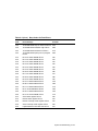
Table 2–2 (Cont.) POST and Boot Messages
POST No.
Error Name
Description
Solution
100
Shadow ROMs
Shadow of off-board
video BIOS failed
The video controller
board might have
failed. Check
that it is installed
correctly. Run the
SCU. Also, see 700.
090
Enable cache
Internal cache test
failed, cache disabled
Cache failed.
Replace the CPU
module.
080
Initialize option ROMs
XXXX0h optional ROM
bad checksum=YYh
Expansion board
configuration error.
Run the SCU.
070
Set system clock
Time of day clock not set
Run the SCU.
060
Check for electrical
keylock
Keyboard is locked,
please unlock
Unlock the
keyboard.
043
Invalid EISA configuration information
An EISA board has
not been properly
configured. Run
the SCU and verify
all settings. Make
sure that an EISA
CFG file has been
installed for the
module.
042
Invalid ISA configuration information
An ISA board has
not been properly
configured. Run
the SCU and check
switch and jumper
settings. Make
sure that an ISA
CFG file has been
installed for the
module.
(continued on next page)
System Troubleshooting 2–13
Table 2–2 (Cont.) POST and Boot Messages
POST No.
Error Name
041
040
Report configuration
errors and prompt for
configuration utility
020
Enable parity checking
and NMI
004
Description
Solution
ID mismatch error,
slot X
(A) The board in
slot X is bad and
returns a bad ID.
(B) The board ID
does not match the
ID that the SCU
expects for slot
X. The mismatch
is due to either
the wrong board
in the slot or the
wrong configuration
file for the board.
Run the SCU to
configure slot X,
or replace the bad
board.
Configuration error,
slot X
Run the SCU for
the board in slot X.
No boot sector on hard
drive
The hard disk drive
is not formatted
as a bootable disk.
Format the drive.
(continued on next page)
2–14 System Troubleshooting
Table 2–2 (Cont.) POST and Boot Messages
POST No.
Error Name
Description
Solution
003
Hard drive read failure
The hard disk
drive has failed.
Check the system
configuration and
drive type by
running the SCU.
Check both ends
of the controller’s
cables, and reseat
the hard disk
controller board.
Try another hard
disk drive. If the
problem persists,
replace the hard
disk controller.
002
No boot device available
If booting from a
diskette, it is a
nonbootable type
or the diskette
drive has failed.
If booting from a
hard disk drive,
it might not be
formatted or the
drive might have
failed. The problem
might also be the
SCSI controller
board. Make sure
the diskette in
drive A contains an
operating system.
If applicable, make
sure the hard disk
drive contains an
operating system.
(continued on next page)
System Troubleshooting 2–15
Table 2–2 (Cont.) POST and Boot Messages
POST No.
Error Name
001
000
Boot
Description
Solution
Not a bootable diskette
The diskette in
drive A is not
formatted as a
bootable diskette.
Replace the
diskette with a
bootable diskette
and try again.
Diskette read failure
No diskette in drive
A. Insert a diskette
and try again.
2.3.5 Beep Codes
If POST finds an error and cannot display a message, the system board speaker
beeps to indicate the error and places a value in I/O port 80h. For example, a
failure of bit 3 in the first 64 KB of DRAM is indicated by a 2-1-4 beep code (a
burst of two beeps, a single beep, and a burst of four beeps).
Tables 2–3 and 2–4 list the beep codes and the values POST writes to I/O port
80h when it encounters an error. Table 2–3 lists fatal errors (errors that lock
the computer), and Table 2–4 lists nonfatal errors (errors that do not lock the
computer).
One beep code is not listed in either table: a long beep followed by one or more
short beeps. This beep code indicates a video controller failure.
Table 2–3 Beep Codes for Fatal Errors
Beep
Code
Error Message
Port 80h
1-1-3
Real-time clock write/read failure
02h
1-1-4
ROM BIOS checksum failure
03h
1-2-1
Programmable interval timer failure
04h
1-2-2
DMA initialization failure
05h
1-2-3
DMA page register write/read failure
06h
1-3-1
DRAM refresh verification failure
08h
(continued on next page)
2–16 System Troubleshooting
Table 2–3 (Cont.) Beep Codes for Fatal Errors
Beep
Code
Error Message
1-3-3
1st 64 KB DRAM chip or data line failure
0Ah
1-3-4
1st 64 KB DRAM odd/even logic failure
0Bh
1-4-1
1st 64 KB DRAM address line failure
0Ch
1-4-2
1st 64 KB DRAM parity test in-progress
failure
0Dh
2-1-1
Bit 0 1st 64 KB DRAM failure
10h
2-1-2
Bit 1 1st 64 KB DRAM failure
11h
2-1-3
Bit 2 1st 64 KB DRAM failure
12h
2-1-4
Bit 3 1st 64 KB DRAM failure
13h
2-2-1
Bit 4 1st 64 KB DRAM failure
14h
2-2-2
Bit 5 1st 64 KB DRAM failure
15h
2-2-3
Bit 6 1st 64 KB DRAM failure
16h
2-2-4
Bit 7 1st 64 KB DRAM failure
17h
2-3-1
Bit 8 1st 64 KB DRAM failure
18h
2-3-2
Bit 9 1st 64 KB DRAM failure
19h
2-3-3
Bit A 1st 64 KB DRAM failure
1Ah
2-3-4
Bit B 1st 64 KB DRAM failure
1Bh
2-4-1
Bit C 1st 64 KB DRAM failure
1Ch
2-4-2
Bit D 1st 64 KB DRAM failure
1Dh
2-4-3
Bit E 1st 64 KB DRAM failure
1Eh
2-4-4
Bit F 1st 64 KB DRAM failure
1Fh
3-1-1
Slave DMA register failure
20h
3-1-2
Master DMA register failure
21h
3-1-3
Master interrupt mask register failure
22h
3-1-4
Slave interrupt mask register failure
23h
3-2-4
Keyboard/mouse controller test failure
27h
Port 80h
System Troubleshooting 2–17
Table 2–4 Beep Codes for Nonfatal Errors
Beep
Code
Error Message
Port 80h
3-3-4
Screen memory test failure
2Bh
3-4-1
Screen initialization failure
2Ch
3-4-2
Screen retrace test failure
2Dh
2.4 Setup Utility
The system BIOS also contains a setup utility that enables you to change
configuration settings that are stored in CMOS RAM. BIOS setup options are
the same as those provided in the "Configure computer" option of the SCU,
with the exception of password. For information on configuring the system
with the SCU, refer to Chapter 5.
To run the setup utility, wait for POST to complete. Then, press the
appropriate function key to display the following initial setup screen:
**** NOTE ****
Since values specified using the BIOS Setup Utility will be overwritten when
the system configuration utility (SCU) is run, it is recommended that the BIOS
Setup Utility be used only if you:
o
o
o
Need to enable your diskette drive
Do not have access to a diskette drive
Have only ISA expansion boards and will not be using the SCU
To exit setup press ESC. To continue setup press F1.
Note
Always use the SCU to configure the system. Do not use setup to
configure the system. Setup is used primarily to enable the diskette
drive.
2–18 System Troubleshooting
2.5 Run-Time Error Messages
Run-time error messages are displayed on the monitor if an error occurs after
the system boots. Table 2–5 lists the run-time error messages by number.
Table 2–5 Run-Time Error Messages
POST No.
Message
Solution
988
Software NMI
987
Bus timeout NMI, slot X
986
Unresolved bus timeout NMI
See 985.
985
Fail safe timeout NMI
Expansion board malfunction. Replace
defective board.
984
Expansion board disabled
Configuration error or malfunctioning
expansion board. Run the SCU and
verify settings.
983
Unresolved I/O expansion board
NMI
See 982. Slot is unknown.
982
I/O expansion board NMI, slot X
Malfunction or configuration error for
expansion board in slot X. Run the
SCU and verify settings.
981
Memory parity error at XXXX–
YYYY
See 980.
980
Unresolved memory parity error
Computer DRAM has failed. Replace
any failed SIMM.
971
Unexpected hardware interrupt
This could be any hardware-related
problem. Check all cables, connections,
jumpers, and boards.
970
Unexpected software interrupt
There is an error in a software utility.
Try turning the system off and then on
again.
2.6 Troubleshooting
Follow this general procedure to troubleshoot the system.
1. Press the reset button on the front panel. If your system fails to boot, turn
it off, wait 20 seconds, and then turn it back on.
2. Check for non-bootable diskette in A: (drive A).
3. Check for loose cables and connections.
4. Check the system and monitor indicator lights.
System Troubleshooting 2–19
5. Observe any POST messages. Refer to Section 2.3.4, POST and Boot
Messages, take the appropriate steps to correct the problem, and then reset
the computer.
6. Run the SCU and make sure the system is configured correctly for the
installed hardware and software. For information on configuring the
system with the SCU, refer to Chapter 5.
7. Run the applicationDEC system exerciser (SYSEX). SYSEX tests each
system unit simultaneously with peripheral and communication transfers
to detect interactive errors. For further information on testing the system
with SYSEX, refer to Chapter 3.
8. Contact Digital Customer Services for software or hardware problems.
9. Package the failed component in the original container and return it to
Digital for service.
Tables 2–6 through 2–8 help you to identify and solve system, disk drive, and
monitor problems.
Table 2–6 System Troubleshooting
Problem
Possible Cause
Action
No response when
the system is
turned on
System is not plugged
in
Turn off the system, plug it in, and
turn it on again.
No power at the wall
outlet
Use another wall outlet.
Monitor brightness
and contrast controls
are not properly set
Adjust the monitor brightness and
contrast controls.
Monitor is off
Turn on the monitor.
Monitor cable is
incorrectly installed
Check all monitor connections.
Video expansion board
failure
Make sure the video expansion board
is properly installed and firmly seated.
Operating system
software is not
installed on the IDE
hard disk drive
Install the operating system on the
hard disk.
Power is on, but
there is no monitor
display
System does not
boot from an IDE
hard disk drive
(continued on next page)
2–20 System Troubleshooting
Table 2–6 (Cont.) System Troubleshooting
Problem
System does not
boot from a SCSI
hard disk drive
Possible Cause
Action
IDE hard disk drive is
not properly formatted
or the requested
partition does not
exist
Format the IDE hard disk drive or
correctly partition the IDE hard disk
drive using the supplied operating
system software.
There is no software
on the requested
partition
Install software on the requested
partition.
IDE hard disk drive
jumpers incorrectly set
Refer to the supplied IDE hard disk
drive kit installation instructions.
IDE drive type
incorrect
Run the SCU to identify the correct
drive type.
Loose cables
Check all cable connections.
Operating system
software is not
installed on the SCSI
hard disk drive
Install the operating system.
Requested partition
does not exist
Partition the SCSI hard disk drive and
then reload the operating system.
SCSI hard disk drive
jumpers incorrect
Refer to the supplied SCSI hard disk
drive kit installation instructions.
SCSI ID conflicts
Refer to the supplied SCSI hard disk
drive kit installation instructions on
setting SCSI IDs.
Terminating resistors
not removed from the
SCSI hard disk drive
Remove terminating resistors. Refer
to the supplied kit installation
instructions.
System not configured
for SCSI hard disk
operation
Run the SCU to configure the system
for SCSI operation.
IDE drive is configured
in the system
Remove the IDE drive or install the
boot software on the IDE drive.
(continued on next page)
System Troubleshooting 2–21
Table 2–6 (Cont.) System Troubleshooting
Problem
Possible Cause
Action
System does not
boot from a target
diskette drive
Drive ID incorrectly
set
Make sure the drive ID is correctly set.
Diskette drive not
enabled
Run setup utility to enable diskette
drive.
Diskette does not
contain start-up files
Insert diskette with correct start-up
files.
Diskette drive is empty
Insert the diskette that contains an
operating system.
Diskette is worn or
damaged
Try another diskette.
Loose cables
Check all cable connections.
System will not
boot from system
configuration
diskette
System configuration
diskette faulty
Use another system configuration
diskette.
No response
to keyboard
commands
Keyboard is password
protected
Run the SCU to enter the keyboard
password.
Keyboard is not
connected
Connect the keyboard.
Keyboard is connected
to the mouse port
Connect the keyboard to keyboard port.
Keyboard is locked
Unlock the keyboard.
2–22 System Troubleshooting
Table 2–7 Disk Drive Troubleshooting
Problem
Possible Cause
Action
IDE/SCSI hard
disk drive cannot
read or write
information
Incorrect jumper
settings
Refer to the supplied kit installation
instructions.
Loose or incorrectly
installed cables
Make sure all cables are correctly
installed.
IDE/SCSI hard
disk drive is not
properly formatted
or partitioned
Format and partition as required using
the supplied operating system.
IDE drive type
incorrect
Run the SCU to identify the correct
drive type.
System not configured
for SCSI hard disk
operation
Run the SCU to configure the system
for SCSI operation.
Diskette is not
formatted
Format the diskette.
Diskette is worn or
damaged
Try another diskette.
Diskette is writeprotected
Slide the write-protect switch so the
hole is not visible (3.5-inch diskette)
or uncover the write-protect notch
(5.25-inch diskette).
Diskette drive is empty
Insert a diskette.
Target diskette
drive cannot
read or write
information
System Troubleshooting 2–23
Table 2–8 Monitor Troubleshooting
Problem
Possible Cause
Action
Monitor power
indicator is not on
Monitor is turned off
Turn on the monitor.
Power cord is not
connected
Connect the power cord to the system.
No power at wall
outlet
Use another outlet.
Power indicator is
defective
Replace monitor.
Configuration error
Check video board cabling and jumper
settings.
Monitor brightness
and contrast controls
are not properly set
Adjust the monitor brightness and
contrast controls.
Monitor incorrectly
adjusted
Adjust accordingly.
Monitor signal cable
incorrectly installed
Straighten any bent connector pins
and then reseat.
System was turned on
before the monitor was
turned on
Turn off the system and monitor, turn
on the monitor, and then turn the
system on.
No monitor display
Distorted, rolling,
or flickering
screen display,
or wrong/uneven
color
Color monitor
displaying
monochrome
2–24 System Troubleshooting
3
System Exerciser
3.1 Overview
The applicationDEC system exerciser (SYSEX) is a standalone, diskettebased diagnostic that detects and isolates hardware problems to the field
replaceable unit (FRU) level. SYSEX tests each system unit simultaneously
with peripheral and communication transfers to detect interactive errors.
Note
Version 4.0 or higher of the applicationDEC System Exerciser is
required for use with the applicationDEC 400xP system.
SYSEX verifies the following:
•
System motherboard logic
•
Memory expansion module
•
Serial port (COM1, COM2) logic
•
Parallel port (LPT1) logic
•
Terminal multiplexer module
•
EtherWORKS Turbo Ethernet controller
•
3.5-inch diskette drive
•
5.25-inch diskette drive
•
2.2 GB helical 8 mm tape drive (TKZ08)
•
320/525 MB QIC tape drive (TZK10)
System Exerciser 3–1
•
Digital hard disk drives:
209 MB disk drive (RZ24)
426 MB disk drive (RZ25)
665 MB disk drive (RZ56)
852 MB disk drive (RZ35)
1.0 GB disk drive (RZ57)
1.3 GB disk drive (RZ58)
You can run the system exerciser two ways:
•
The installation verification procedure (IVP) performs a 15-minute (default
time) test session that returns the system status.
•
The run command executes the system exerciser tests continuously.
Press
Ctrl/C
to halt SYSEX at any time.
The SYSEX commands let you run, halt, and block tests. In addition, you
can display the following information:
•
System configuration
•
Data at specified locations
•
Status of tests and devices
•
Error reports
You can dedicate CPU resources to specified tests by blocking unwanted tests.
Section 3.9.1 provides information on how to block tests.
3.2 Loading the System Exerciser
Load the system exerciser as follows:
1. Insert the system exerciser diskette into the 3.5-inch diskette drive.
2. Boot the system from the diskette in either of the following ways:
•
Turn the system power off and then on again.
•
Press the reset switch on the front panel.
If a bad checksum message is displayed, see Section 3.4.
3–2 System Exerciser
3.3 Running the System Exerciser
Note
Before you run SYSEX, verify the system configuration with the system
configuration utility (SCU). For information on configuring the system
with the SCU, refer to Chapter 5.
When the system exerciser has been booted, system configuration information
is displayed on the screen:
03/12/92 15:00:08 applicationDEC System Exerciser Rev 4.0 400xP
applicationDEC System Exerciser
Rev 4.0
03/01/92
0000:00:00
applicationDEC 400xP
Copyright (c) Digital Equipment Corporation, 1991, 1992. All Rights Reserved.
Unpublished-rights reserved under the copyright laws of the United States.
Verifying program loaded correctly
System Configuration:
Slot
Type
====
====
0
33MHz Viceroy Motherboard
0
0 KB Secondary Cache
0
16MB Memory
EISA
Slot
====
0
0
0
0
0
1
3
2
slot
IRQ
===
6
7
4
3
configuration:
Ports
Type
=====
====
3F0-3F7
Floppy controller
378-37B
Parallel port, LPT1
3F8-3FF
Serial port, COM1
2F8-2FF
Serial port, COM2
Video Adapter (80x25 color)
10 D0000
8x4 Mux
11 330-332
Adaptec 1540B, firmware rev = 05
5 300-30C
DE200 Ethernet, Node addr = 08-00-2B-27-73-31
Load scratch media into all drives to be tested in write-read mode
Hit any key to continue
After you load the drives to be tested, press
displayed.
Enter .
The following message is
Is a printer connected to COM1 (Y/N)?
Enter your response by pressing
Y
or
N.
The following message is displayed:
Sizing devices (please wait - up to 5 min.) ...
System Exerciser 3–3
Then you are prompted to select destructive (write/read) or nondestructive
(read only) testing for each device:
Test mode selection. Use keyboard to make selections.
Space key selects write/read testing. ENTER key protects media.
The screen should resemble the following display during and after test mode
selections:
BUS Configuration:
Slot ID LUN
Device
0
0
*
Disk
0
1
*
Disk
3
0
0
Disk
3
1
0
Disk
Type
Rev
Selection
RX23/1.44M
Protected
RX33/1.2M
Read only
RZ25
(C) DEC 0700 Read only
RZ24
(C) DEC 211B Read only
Next, you are prompted to enable or disable external loopback testing:
Loopback Selection. Hit SPACE to enable external loopback, ENTER to disable.
1
D0000 8x4 Mux
A-C disabled
B-D disabled
00
00
00
COMM1
COMM2
LPT1
disabled
disabled
disabled
Note
If you selected destructive (write/read) testing for any device, the
following message is also displayed:
******************************************
* WARNING! Destructive testing enabled. *
* Data will be lost when testing begins! *
******************************************
If loopback testing is enabled, loopback connectors must be installed on
the enabled ports (8x4 mux, serial port 1, serial port 2, parallel port) or
the related tests will fail.
The next display shows the tests that the system exerciser will run. The
display is based on the selections you made and the recognized system
configuration.
3–4 System Exerciser
Scheduled tests:
Test
====
1.
2.
3.
4.
5.
6.
7.
8.
9.
10.
11.
12.
13.
14.
Name
Rev
====
===
Memory
1
Memory Retention
1
Numeric
0
Serial Line (COM1) 2
Serial Line (COM2) 2
Motherboard [Slot 0] 2
Parallel Port (LPT1) 1
Console
1
SCSI Disk 3:0:0
1
SCSI Disk 3:1:0
1
Floppy Disk 0:0
1
Floppy Disk 0:1
1
8x4 Mux
[Slot 11] 2
Ethernet/2 (DE200) 0
Type "HELP" for information, "RUN" or "IVP" to begin testing
HLT>
When the HLT> prompt is displayed, you can run the 15-minute installation
verification procedure (IVP). Type the ivp command and press Enter :
HLT> ivp
Enter
You can run the IVP for less than the full 15 minutes by specifying a number
of minutes in the ivp command. The following command specifies 5 minutes:
HLT> ivp 5
Enter
When the IVP is running, the following message is displayed:
Installation Verification Procedure Running
Also, the HLT> prompt will change to RUN>.
After 15 minutes (default time), a success message is displayed, indicating that
the system is functional. Then the HLT> prompt is reissued:
Installation Verification Procedure Complete: No Errors Detected
HLT>
If an error is detected, an error report is displayed immediately and the IVP is
aborted. See Section 3.5 for details on how to interpret the error report.
If you wish to rerun the IVP, you must reboot the system exerciser. You cannot
rerun the IVP by typing ivp again. By typing the run command, you can run
the same tests without rebooting the system, but the tests run continuously
(without the 15-minute timeout).
Type status to see error summaries. Press
to reboot.
Ctrl/C
to stop the tests. Type quit
System Exerciser 3–5
3.4 Loading Failure
After you load SYSEX, one or two messages appear on the console monitor. If
the only message is the following, loading was successful:
Verifying program loaded correctly
If the error report ‘‘Checksum error detected at load time’’ follows the above
message, the loading failed. Take the following action:
1. Reload the diskette.
2. Reboot. If this fails to correct the loading failure, try a different SYSEX
diskette in case the first diskette is bad.
3. If this load also fails, check for failed memory or a bad load path. A bad
load path occurs when either the diskette drive itself is bad or the cable
to the diskette drive is bad. Section 4.9 provides information on replacing
memory modules.
4. Run the POST tests again for possible further information.
3.5 Error Reports
If SYSEX detects an error condition or a failed FRU, an error report is
displayed on the monitor and written to the error log. By default, SYSEX
stops execution when an error is detected. (Information in the error log can be
displayed using the log command.)
Each error report calls out a FRU. Because there may be more than one of any
type of FRU in the system, additional information is provided to identify which
of the multiple units has failed:
•
For modules, the slot number indicates the module which has failed.
•
For SIMM failures, the socket number of the failed SIMM is indicated.
•
For SCSI storage devices, the bus ID and logical unit number of the device
is indicated. Also, the slot number of the associated adapter is identified.
SCSI devices controlled by an ISA SCSI adapter or an EISA SCSI adapter
are identified by the slot number of the adapter.
3–6 System Exerciser
The following SYSEX error report shows that the loopback plug was found
missing during external loopback testing of serial port 1 (COM1):
applicationDEC System Exerciser Rev: 4.0 03/01/92 (400xP)
Current time = 03/12/92 15:50:06
Test # 4
Serial Line (COM1) 2
Passes 1828
Errors 1
Task # 3
Elapsed time = 2:41:58
Subtest # 3
Processor # 0 Slot: 0
FRU = slot 0 Serial Port, loopback plug
Registers at time of error:
eax = 44E924FE ebx = 44E9245F ecx = 0000FF04 edx = 000003F8
esi = 00001000 edi = 0000005F
Error address = 33F
Current UART registers:
LCR = 3B
MCR = 18
LSR = 60
MSR = 8A
DL = 11F
Test: External loopback (xmit -> rcvr)
Interrupt wait elapsed, outstanding interrupts = 9.
Transmit string, length = 9.
CC AC 7E 78 75 0C 38 C2 29
Receive string, length = 0.
After an error, continued testing is dependent on the state of the halt flag:
Halt flag on = suspend test execution (until the run command is reissued)
Halt flag off = continue test execution (immediately after completion of
error report)
Before replacing a FRU identified by SYSEX:
1. Make sure that the module in the designated slot is the correct module for
the slot.
2. Make sure that all switches and jumpers are set correctly on the module.
3. Check any cable connections.
4. Reseat modules installed in the EISA bus slots.
Now, rerun SYSEX. If the same FRU is called out again, replace the FRU.
System Exerciser 3–7
3.6 Test Descriptions
Table 3–1 describes the system exerciser tests.
Table 3–1 System Exerciser Tests
Name
Description
Memory
Write/read main memory.
Memory retention
Memory refresh circuitry.
Numeric
CPU floating point.
Motherboard
System motherboard logic.
Console
Writes test patterns to the console for visual verification.
Terminal multiplexer
Internal/external data loopback and registers.
Serial port (COM1, COM2)
Internal/external data loopback and registers.
Parallel port (LPT1)
Internal/external data loopback and registers.
Floppy
Write/read (destructive) or read-only (nondestructive)
verification. User selectable. Requires that diskette be
installed in device.
Ethernet
Send, receive, and verify messages internally and with
other network nodes.
SCSI disk
Write/read (destructive) or read-only (nondestructive)
verification. User selectable.
SCSI tape
Write/read verification. Requires that tape cartridge be
installed in device.
3.7 Modes
The system exerciser has two modes. The modes are described in Table 3–2.
Table 3–2 System Exerciser Modes
Mode
Prompt
Meaning
Halt
HLT>
Tests have not begun or testing is suspended.
Run
RUN>
Tests are running.
You can run most SYSEX commands in either mode. The exceptions are the
ivp command, which is valid only in the halt mode, and the istep command,
which is valid only at a breakpoint.
3–8 System Exerciser
You can place SYSEX in the halt mode at any time by pressing Ctrl/C . Because
no tests are running when SYSEX is in the halt mode, response to commands
is immediate. When SYSEX is in the run mode and tests are running, the keys
you press are echoed to the screen as they are typed, but the commands are
not executed until the completion of the current test pass. This can sometimes
cause a short delay.
3.8 Flags
You can set flags to control whether:
•
Information sent to the console monitor and the error log should include
data about memory allocation, task swapping, and segment descriptors.
•
Information is sent to the console monitor in one-screen segments.
•
Testing should continue when an error is encountered.
•
Console output should be echoed to a serial printer on the COM1 port.
•
Failing tests should automatically block themselves.
Flags are set with the flag command. Table 3–3 describes the SYSEX flags.
Table 3–3 System Exerciser Flags
Flag
Default
Description
Halt
On
Stop testing when error is reported; return to halt mode prompt.
If off, continue testing after an error is reported.
Long
Off
Include test environment information in the error report. This
information describes the machine state during the most recent
task swaps, segment descriptor data, and the memory allocation
table. If off, generate an abbreviated error report that contains
only the header block and text.
More
Off
Displays information on the console in one-screen segments.
Press Enter to display the next line of information. Press
Spacebar to display the next screen of information. Press Q
to stop displaying information. If off, any information containing
more than 23 lines will have some lines that scroll off the console
monitor.
Print
Off
Allows the console output to be echoed to a serial printer on the
COM1 port. The print flag is ignored if the startup ‘‘ Is a printer
connected to COM1 (Y/N)?’’ question is not answered with Y.
Threshold On
Automatically blocks any test that reaches the error threshold.
The threshold is ten failed passes in a row. If off, allows the
failing test to keep running and reporting failures.
System Exerciser 3–9
Use the flag command to change the status of a flag. For example, to set the
long flag, enter the following:
HLT> flag on long
Enter
If you boot the system, the SYSEX flags return to the default settings.
3.9 Commands
Table 3–4 lists the system exerciser commands. The commands are not case
sensitive and may be abbreviated.
Table 3–4 System Exerciser Commands
Command
Description
B[lock]
Prevent specified tests from running.
B[lock] {no argument}
Display all tests that are currently blocked from running.
Cac[he]
Set internal processor cache state (enabled or disabled).
Cac[he] {no argument}
Display current state (enabled or disabled) of the internal
processor cache.
Cal[culate]
Make a calculation in one of three radices: decimal, octal, or
hexadecimal. Hexadecimal is the default radix.
Co[nfiguration]
Display the configuration of the system.
Ctrl/C
Halt testing; return to the halt mode prompt.
De[vices]
Display or modify the flag state of devices under test.
De[vices] {no argument}
Display a list of the supported devices.
Di[splay]
Display the data at specified locations in memory.
E[xamine]
Examine the data at a specified location in memory. You
can also deposit data at the specified location in memory.
F[lags]
Modify the flag settings.
F[lags] {no argument}
Display the state of all flags (on or off).
G[o]
Set and run until a breakpoint.
H[elp]
Obtain information on any command.
H[elp] {no argument}
Display a list of all system exerciser commands.
Is[tep]
Execute individual instruction(s) while in debug mode.
Ivp
Run the installation verification procedure.
(continued on next page)
3–10 System Exerciser
Table 3–4 (Cont.) System Exerciser Commands
Command
Description
L[og]
Play back or delete previous error reports or write error
reports to a DOS diskette.
Q[uit] or Ctrl/Alt/Delete
Stop all tests and reboot the system.
R[un]
Begin or resume testing (change from halt mode to run
mode).
Se[t]
Set or display the values of state variables.
Se[t] {no argument}
Display a list of all state variables.
Sh[ow]
Show a machine state.
Sh[ow] {no argument}
Display a list of all available machine states that can be
shown.
St[atus] or
Ctrl/T
Display which tests are running, whether they are blocked,
and how many test passes have been made.
T[ime]
Display current date and time and elapsed test time.
U[nblock]
Allow tests that have been blocked to resume running.
U[nblock] {no argument}
Display all tests that are currently unblocked.
3.9.1 Block
Use the block command to prevent one or more tests from running. This
might be helpful if you want to focus CPU time on one test. For example, you
might want to eliminate a test from which you have already gathered sufficient
error information, or you might want to eliminate constantly scrolling error
reports from a failing test.
Format: BLOCK [option_argument]
Table 3–5 describes the options that you can use with the block command.
Table 3–5 Block Command Options
Command
Description
B[lock]
Display all tests that are currently blocked.
B[lock] t
Block the specified test.
B[lock] t-t
Block a range of tests that begins with the first test number specified
and ends with the second test number specified.
System Exerciser 3–11
For example, to block test 1:
RUN> block 1
Enter
If you look at the test status, the display indicates that test 1 is blocked by
placing the letter B next to the number of the test.
To block test 1 and test 3, use either of the following:
RUN> block 1 3
Enter
RUN> block 1,3
Enter
To block test 1, test 2, and test 3:
RUN> block 1-3
Enter
3.9.2 Cache
The cache command lets you set or display the state (enabled or disabled) of
the internal cache.
Format: CACHE [enable,disable]
If no argument is given, the cache command displays the current state of the
cache.
RUN> cache disable
Enter
3.9.3 Calculate
The calculate command lets you make calculations and includes functions
similar to a pocket calculator, such as addition, subtraction, multiplication, and
division.
Format: CALCULATE[/radix] argument_list
The calculate command provides support for the following three radices:
•
Octal
•
Decimal
•
Hexadecimal (default)
The result of the calculation is displayed in all three radices in the order octal,
decimal, hexadecimal.
The calculate command is a convenient way to convert radices.
Table 3–6 describes the qualifiers that you use to set the default radix for all
numbers in a calculation.
3–12 System Exerciser
Table 3–6 Calculate Command Qualifiers
Command
Description
Cal[culate]/o
Cal[culate]/d
Cal[culate]/h
Calculate using the octal radix.
Calculate using the decimal radix.
Calculate using the hexadecimal radix.
Hexadecimal is the default radix. If you set the default radix to decimal
or octal, the system immediately defaults back to hexadecimal when the
calculation is finished.
To convert the value of 100 octal to hexadecimal or decimal, use the following
command:
HLT> caculate/o 100
100, 64, 40
Enter
To convert the value of 100 decimal to octal or hexadecimal, use the following
command:
HLT> calculate/d 100
144, 100, 64
Enter
To see the value of 100 hexadecimal in the three radices, use the following
command:
HLT> calculate 100 Enter
400, 256, 100
Note that because hexadecimal is the default, you do not have to specify /h
when calculating in hexadecimal.
If you use more than one radix in a calculation, use the symbols shown in
Table 3–7 to specify the radix of an individual number.
Table 3–7 Calculate Command Radix Symbols
Radix
Symbol
Example
Decimal
Hexadecimal
Octal
.
h
o
10.
10h
10o
For example, in the equation that follows, the number 13 is hexadecimal, 59 is
decimal, and 100 is octal:
HLT> calculate 13 + 59. + 100o
216, 142, 8e
Enter
System Exerciser 3–13
You can use the following functions with the calculate command:
•
Add ( + )
•
Subtract ( - )
•
Multiply ( * )
•
Divide ( / )
•
Exponentiation ( ^ )
The order of precedence is:
•
Exponentiation (highest precedence)
•
Multiply or divide
•
Add or subtract (lowest precedence)
Use parentheses to change the order.
3.9.4 Configuration
The configuration command lets you display the same system and EISA bus
configuration information that was displayed during initial SYSEX startup.
Format: CONFIGURATION
RUN> configuration
Enter
3.9.5 Ctrl/C
Press
Ctrl/C
at any time to suspend testing and enter halt mode.
Note that although testing is stopped when suspended, the clock that measures
elapsed test time continues to operate. The clock will always reflect the elapsed
time since you started testing. If you suspend testing, the clock does not reflect
the actual test time.
3.9.6 Devices
The devices command lets you display or modify the flag state of devices
under test.
Format: DEVICES [device[/n] [flag_list]
The devices command is extremely useful for changing the test state of
devices that were set up incorrectly at the start. Without this command, you
would have to reboot SYSEX to set up the device tests differently.
3–14 System Exerciser
For example, if you select destructive (write/read) testing for a disk that
really should be write protected, then you can use this command to change to
nondestructive (read only) testing for the disk. Or, if you set up a COM or LPT
for external loopback testing and find that loopback plugs are not installed,
then you can use the devices command to reconfigure the COM or LPT for
internal loopback testing only.
The first argument must be the name of the requested device. The /n modifier
can be used to request a specific device of the type given. The following
example specifies COM2 and no other COM devices:
RUN> devices com/2
Enter
The format of the /n modifier depends on the device type. Table 3–8 shows the
format for each device type.
Table 3–8 Devices Command Formats
Device Type(s)
Format
Description
COM
LPT
n
n = device port number
Disk
x:y[:z]
x = disk adapter slot number
y = SCSI ID address
z = logical unit number (hard disk drives only)
Ethernet
n
n = device slot number
If the /n modifier is not provided, then all devices of the given type will be
affected.
A flag list can be included in the command line, which will cause the specified
device flag(s) to be set to the requested state. When a flag list is not included,
the current state of the specified device(s) is displayed. A flag list has the
format (enable/disable) flag1, flag2, ..., flagn. You must specify the state
followed by a list of all flags that should be set to that state.
The /n modifier for the disk device type has the format x:y[:z], where x:y:z
specifies the disk whose flag state should be displayed or modified. The disk
number can be found in the test list. For example, dev disk/0:0 specifies the
RX23 diskette drive, and dev disk/3:1:0 specifies a disk on the SCSI bus.
Table 3–9 shows the available state flags for supported devices.
System Exerciser 3–15
Table 3–9 Devices Command State Flags
Device
Flag(s)
Description(s)
COM
Lpbk
External loopback
Disk
Protect
Data protect flag1
Ethernet2
Auto_census
Census
Int_lpbk
Network
Automatic census every ‘‘time x’’ minutes3
Issue census command
Internal loopback4
Network testing5
LPT
Lpbk
External loopback
MUX
AClpbk, BDlpbk
A->C and B->D loopback flags
1
Enabled runs test as read only.
2
Ethernet devices support two additional command qualifiers: add and remove. You use these
qualifiers to add node addresses to the network partners table or to remove nodes from test. The
remove qualifier leaves the entry in the table, but sets the status to ‘‘not testing’’. Following the
qualifier verb is the node address in the form xx-xx-xx-xx-xx-xx, which is the 48-bit LAN address.
An example is dev ether add 08-00-2B-5E-1C-5A.
3
Automatic census can be disabled for network devices to prevent periodic census commands from
being issued. The time interval can also be set to zero in order to disable the automatic census
feature. To set the time, enter the command dev ethernet/n enable auto x, where x is the time
in munutes.
4
Versus external loopback.
5
Versus internal or external loopback testing. If network testing is enabled, test packets are sent
to other nodes on the network. If network testing is disabled, then either internal or external
loopback testing is performed, based on the state of the int_lpbk flag.
3.9.7 Display
The display command lets you display data at specified locations in memory.
Format: DISPLAY[/mode] [address]
Data can be displayed in the following modes:
•
Byte (default)
•
Word
•
Doubleword
•
ASCII
To choose a display mode, use one of the display command qualifiers shown in
Table 3–10.
3–16 System Exerciser
Table 3–10 Display Command Qualifiers
Command
Display Mode
D[isplay]/b
D[isplay]/w
D[isplay]/d
D[isplay]/a
Byte (default)
Word
Doubleword
ASCII
If you do not designate an address, the system defaults to the last address
selected for display or to address 0 if no previous display command was
executed.
Addresses have the format task:seg:offset. The task:seg fields are optional,
but are always displayed by the system. The offset field is required and is the
address offset within the segment. For example, to display the data in the byte
display mode (default) at address location 32F (hex) in segment 8 (default), use
either of the following:
HLT> display 32f
0:8:32F 53
Enter
HLT> display 0:8:32f
0:8:32F 53
Enter
You can also specify an argument list to display an address range. The range
can be any size from one unit or more and can be in ascending or descending
order. The range is specified as addr addr (starting address, ending address)
or as addr length value (starting address, length qualifier, length value in
display mode units).
In addr addr mode, the ending address is another offset within the segment. If
the ending offset (address) is greater than the starting offset, then memory is
displayed in order of ascending addresses. If the ending offset is less than the
starting offset, data is displayed in descending order.
In addr length value mode, the length value specifies how many units (byte,
word, and so on) of data to display beginning with the starting address. If
the length is a positive number, data is displayed in ascending addresses.
A negative length displays addresses in descending order. For example, to
display eight doublewords of data beginning at location 32FH in segment 8
(default), use the following:
HLT> display/dword 32f length 8 Enter
0:8:32F F000FF53 F000FF53 F105ED41 F000FF53
0:8:33F F000FF53 F000EDF2 F0008C8C F000FF53
System Exerciser 3–17
3.9.8 Examine
The examine command lets you analyze and modify data at a specified
location in memory.
Format: EXAMINE[/mode] [address]
When data is displayed, the system cursor remains in place and waits for
you to input new data. To modify the data at the current location, input the
new data and then use the " , # , or Enter keys to store the new data. With or
without data modification, the " key examines data at the previous location in
memory. The # key examines data at the next location in memory. The Enter
key exits examine mode.
The ESC key exits examine mode, but will not modify the location whether
new data was typed in or not.
You can examine the contents of memory as bytes, words, doublewords, or as
ASCII by using the examine command qualifiers shown in Table 3–11.
Table 3–11 Examine Command Qualifiers
Command
Display Type
E[xamine]/b
E[xamine]/w
E[xamine]/d
E[xamine]/a
Byte (default)
Word
Doubleword
ASCII
If you do not designate an address, the system defaults to the last address
selected for examination or to address 0 if no previous examine command was
executed.
3.9.9 Flags
The flags command lets you display or modify flags.
Format: FLAGS [flags_list]
See Section 3.8, Flags.
3–18 System Exerciser
3.9.10 Go
The go command lets you set and run until a breakpoint.
Format: GO[/n] [(instruction,write,access,task,forever) (byte,word dword) addr]
The go command is an advanced feature of the system exerciser debugger and
is reserved for use by Digital Equipment Corporation development personnel.
Debug operations at the lowest hardware levels are extremely complex and can
result in unexpected consequences.
3.9.11 Help
The help command lets you view on-line help information.
Format: HELP [command]
RUN> help display
Enter
3.9.12 Istep
The istep command lets you execute individual instruction(s) while in debug
mode. The istep command can be issued only from a breakpoint.
Format: ISTEP [n]
The istep command is an advanced feature of the system exerciser debugger
and is reserved for use by Digital Equipment Corporation development
personnel. Debug operations at the lowest hardware levels are extremely
complex and can result in unexpected consequences.
3.9.13 Installation Verification Procedure (IVP)
The ivp command lets you verify system functionality within 15 minutes
(default time) of testing.
Format: IVP [test_time_in_minutes]
HLT> ivp
Enter
When the IVP starts, the system displays the following message:
Installation Verification Procedure Running
After 15 minutes (default time) of error-free operation, a success message is
displayed, indicating that the system is functional. Then the HLT> prompt is
reissued:
Installation Verification Procedure Complete: No Errors Detected
HLT>
If an error is detected, an error report is displayed and the IVP is aborted. See
Section 3.5 for details on how to interpret the error report.
System Exerciser 3–19
If you wish to rerun the IVP, you must reboot the system exerciser or type run
to continue running SYSEX tests, but without the 15-minute (default time)
timeout.
3.9.14 Log
The log command lets you write error reports to a DOS diskette, play back
error reports that have been logged, and remove reports from the log.
Format: LOG[/error, /recovered] [<PLAY,CLEAR> entry_number, last]
or
Format: LOG ARCHIVE filename.ext
Table 3–12 describes options that can be used with the log command.
Table 3–12 Log Command Options
Command
Description
L[og]
L[og]
L[og]
L[og]
L[og]
L[og]
Display error log summary.
Write all error reports to a DOS diskette.
Remove specific error reports.
Remove all error reports.
Play back specific error reports.
Play back all error reports.
archive filename.ext
clear entry-number
clear
play entry-number
play
RUN> log
Enter
Table 3–13 illustrates a typical log summary report.
Table 3–13 System Exerciser Error Log Report, Example
Entry
Error
Test
Log Address
0
1
2
1
2
3
9
6
15
28316
27FFA
27AB2
The Entry column denotes which entry from the error log is being described.
The Error column denotes whether this is the first, second, third, or nth
encounter of an error in the test run. The Test column denotes which of the
SYSEX tests reported the error. The Log Address column describes where the
report is logged in memory.
3–20 System Exerciser
To review an error report from the log, use the log play command and specify
the entry number of the error. For example, to review entry 0 from the sample
report in Table 3–13:
RUN> log play 0
Enter
You can specify one entry number to review a single error report or a range of
entry numbers to review several error reports. However, you cannot enter both
single numbers and a range of numbers on the same command line.
Memory space for error reports is limited, but there should be space available
for at least 50 error reports.
Note
When the error log is full, new error reports are not included in the
error log. Errors must be cleared before new error reports can be
included.
To remove an error report from the log, use the log clear command and specify
an entry number obtained from the error summary report. For example, to
remove entry 0 from the sample report in Table 3–13:
RUN> log clear 0
Enter
Note
Error reports that have been removed from the error log are
permanently deleted; they cannot be restored.
You can specify one entry number to remove a single error report or a range
of entry numbers to remove several error reports. However, you cannot enter
both single numbers and a range of numbers on the same command line.
System Exerciser 3–21
3.9.15 Quit
You can use the quit command to end a test run and reboot the system.
Format: QUIT
You can also use the key sequence
Ctrl/Alt/Delete
to duplicate the quit command.
3.9.16 Run
The run command lets you run SYSEX tests continuously.
Format: RUN [test_time_in_minutes]
To start or resume testing, enter run or r at the HLT> prompt as follows:
HLT> run
RUN>
Enter
All unblocked tests begin executing immediately. Devices are tested
concurrently. Testing continues until you press Ctrl/C or until an error is
encountered while the halt flag is on. Section 3.8 provides information on how
to use SYSEX flags.
While the tests run, you can execute the status command at the RUN> prompt
to obtain information about SYSEX tests.
3.9.17 Set
The set command lets you set or display state variables.
Format: SET [variable [value]]
Table 3–14 describes the available state variables that you can set or display.
3–22 System Exerciser
Table 3–14 Set Command State Variables
State
Variable
Baud
Status
Value(s)
Description
2400
4800
9600
Baud rate of the line printer on the COM1 port. This variable
is valid only if there is a printer available on the COM1 port.
n
•
Viewing or setting the baud variable is illegal if the
startup ‘‘ Is a printer connected to COM1 (Y/N)?’’ question
is not answered with Y.
•
Specifying an incorrect baud value is flagged as illegal
and the current baud rate is not changed.
Auto status display. Automatically displays test status every n
minutes when n is set to a value greater than zero. When the
value of n is zero, automatic test status displays are disabled.
•
Auto status display lets you see a recent test status in the
event that the system gets into a hung state. This feature
is useful on systems that are monitored at infrequent
intervals.
•
Auto status display does not occur if SYSEX is in halt
mode or is at the MORE prompt when status is ready to
be displayed.
If you do not specify a state variable, a list of all available state variables is
displayed:
HLT> set Enter
Avaliable state to be set:
BAUD
STATUS
If you specify a state variable without providing a new value, the current value
of that variable is displayed:
HLT> set status Enter
Status auto display time = 8
To set a state variable, specify the variable and the new value. The following
example sets the baud rate state to 9600 baud:
HLT> set baud 9600
Enter
System Exerciser 3–23
3.9.18 Show
The show command lets you examine the machine state. Table 3–15 describes
the available machine states that you can examine.
Format: SHOW [machine_state]
Table 3–15 Show Command Machine States
Machine State
Description
Breakpoints
Active breakpoints
GDT
Global descriptor table entries
IDT
Interrupt descriptor table entries
Physical
Physical address of specified logical address
Task
Task state segments for each task
TSS
Individual task state segment
3.9.19 Status
The status command (or Ctrl/T ) lets you display the test statistics for all tests.
The command also lets you display the status of all devices that are under test.
Format: STATUS [option]
The test statistics that you can display are:
•
Test number and description
•
The letter B to the left of the test name, if a test is blocked
•
Test module revision level
•
Total number of test passes made
•
Total number of errors detected in each test
•
Total number of page faults encountered in each test
For example, to obtain the status of all SYSEX tests, enter status or st at the
prompt:
RUN> status
3–24 System Exerciser
Enter
Table 3–16 lists the options for the status command.
Table 3–16 Status Command Options
Command
Description
St[atus]
Display status of all tests.
St[atus] COM[/n]
Display status of COMM port(s) under test.
St[atus] devices
Display status of currently running devices.
1
St[atus] Ethernet/n
Display status of an Ethernet device.
St[atus] network/n1
Display network table for an Ethernet device.
St[atus] t
Display status of specified test.
St[atus] t-t
Display a range of tests that begins with the first test
number specified and ends with the second test number
specified.
1
Device slot number.
3.9.20 Time
The time command lets you display the current date and time and also the
elapsed time since the start of testing.
Format: TIME
RUN> time Enter
03/01/92 15:00:08
applicationDEC System Exerciser Rev 4.0 400xP
0000:07:32
3.9.21 Unblock
The unblock command lets you resume a test that was prevented from
running by the block command.
Format: UNBLOCK [argument_list]
Table 3–17 describes the options that can be used with the unblock
command.
Table 3–17 Unblock Command Options
Command
Description
U[nblock]
Display tests that are currently unblocked.
U[nblock] t
Unblock the specified test.
U[nblock] t-t
Unblock a range of tests that begins with the first test number
specified and ends with the second test number specified.
System Exerciser 3–25
For example, to unblock test 1:
RUN> unblock 1
Enter
To unblock test 1 and test 3:
RUN> unblock 1 3
Enter
RUN> unblock 1,3
Enter
To unblock test 1, test 2, and test 3:
RUN> unblock 1-3
Enter
If you use the unblock command without an argument, a list of all unblocked
tests is displayed on the screen.
3–26 System Exerciser
4
FRU Removal and Replacement
This chapter contains a list of field replaceable units (FRUs) and special
diagnostics tools. It also contains information regarding electric shock and
electrostatic discharge (ESD) that you should read before beginning any FRU
removal and replacement procedure.
4.1 FRU Parts List
Table 4–1 lists the available FRUs for the applicationDEC 400xP system.
Many FRU replacement procedures require you to run the system configuration
utility (SCU) to configure the system. For information on configuring the
system with the SCU, refer to Chapter 5.
Table 4–1 Field Replaceable Units
Part Number
FRU
Order Number
Base System Major Components
30-37794-01
54-21819-01
54-21821-01
54-21823-01
17-00083-39
RX23-AA
System board (EISA, 8-slot)
486/25 MHz CPU module (SX25)
486/33 MHz CPU module (DX33)
486/50 MHz CPU module (DX50)
Power supply (350 W)
US 101-key keyboard
3 button mouse (Logitech)
US power cord (125 V)
14-inch color monitor (1024 x 768, 60 Hz)
RX23 3.5-inch diskette drive (grey bezel)
PS2XK-AA
PS2XK-BA
PS2XK-CA
H7882-AA
PCXAL-AA
PCXAS-AA
BN26J-1K
VRT13-DA
(continued on next page)
FRU Removal and Replacement 4–1
Table 4–1 (Cont.) Field Replaceable Units
Part Number
FRU
Order Number
Options
19-32971-01
19-32971-02
29-28309-01
30-37789-01
29-29052-01
30-37790-01
30-24962-01
TKZ08-AA
30-34761-01
International 102-key keyboard
64 KB cache card (for DX25, DX33)
128 KB cache card (for DX25, DX33)
512 KB video RAM kit
4 MB SIMM kit (2 x 2 MB, 80 ns)
8 MB SIMM kit (2 x 4 MB, 80 ns)
16 MB SIMM kit (2 x 8 MB, 80 ns)
32 MB SIMM kit (2 x 16 MB, 70 ns)
Memory expansion module
Terminal multiplexer kit
8-port terminal concentrator
EtherWORKS Turbo
Adaptec 1520 SCSI adapter
Adaptec 1540B 16-bit SCSI adapter
Adaptec 1740A SCSI adapter
RX33 5.25-inch diskette drive
105 MB IDE 3.5-inch hard disk drive
RZ24-S 209 MB SCSI 3.5-inch hard disk drive
RZ25-S 426 MB SCSI 3.5-inch hard disk drive
RZ35-E 852 MB SCSI 3.5-inch hard disk drive
RZ56-E 665 MB SCSI 5.25-inch hard disk drive
RZ57-E 1.0 GB SCSI 5.25-inch hard disk drive
RZ58-E 1.38 GB SCSI 5.25-inch hard disk drive
TKZ08 2.2 GB SCSI helical tape drive
TZK10-AA 320/525 MB SCSI QIC tape drive
16-inch color monitor (1280 x 1024, multisync)
PCXAL-xx
PSWXM-AA
PSWXM-AB
PSWXM-BA
PS2XM-AA
PS2XM-AB
PS2XM-AC
PS2XM-AD
PS2XM-AE
PC4XD-DA
PC4XD-DB
DE200-AC
PSXAZ-AA
PSXAZ-CA
PSXAZ-BA
PS20R-FA
PC4XR-EB
PS20R-AA
PS20R-BA
PS20R-GA
PS20R-CA
PS20R-DA
PS20R-HA
PS20R-EA
VRC16-DA
Miscellaneous
70-28293-01
70-28294-01
12-22355-12
12-23609-11
12-17119-01
29-26246-01
12-36175-01
Wire assembly, front panel
Wire assembly, DC switch
DC switch, DPST (on-none-off)1
4.5-inch fan, tube axial
Cabinet key
Field engineer ESD kit
Disposable ESD strap
1
The DC switch (12-22355-12) is part of the DC switch wire assembly (70-28294-01), but can be
ordered and replaced separately. The switch is plastic and is connected with push-on terminals.
(continued on next page)
4–2 FRU Removal and Replacement
Table 4–1 (Cont.) Field Replaceable Units
Part Number
FRU
Order Number
Miscellaneous
74-43107-01
70-28286-01
74-43105-01
74-43772-01
74-43102-01
74-42776-01
74-42785-01
70-28259-01
17-02985-02
29-27912-01
70-28301-01
70-28273-02
21-32423-01
Shielding, driver
Stand assembly, plastic stabilizer
Opening insert, plastic
RX23 insert, plastic
Lower rear bezel, plastic
Upper rear bezel, plastic
Upper front bezel, plastic
Lower front bezel, plastic
Diskette drive internal cable assembly
IDE internal cable assembly (part of PC4XR-EB)
System power cable
SCSI internal cable assembly (includes 12-33816-01,
SCSI terminator)
Real-time clock chip (Dallas Semiconductor DS1287)
PSXAZ-DA
4.2 Required Tools
The following tools are required to service the applicationDEC 400xP system:
•
Phillips screwdriver
•
Flat-blade screwdriver
•
Antistatic wrist strap
•
Needlenose pliers (for real-time clock disposal)
•
Insulating tape (for real-time clock disposal)
4.3 Moving the System
To move the system, grasp the handle inside the front bezel (near the top of
the system cabinet) and lift the front of the cabinet slightly. The system can
then be moved by wheeling it on the rear wheels.
FRU Removal and Replacement 4–3
4.4 Before You Begin
Before you open the system cabinet, shut the system down and remove power:
Warning
Risk of electrical shock. Failure to disconnect the source of power
before opening the system can result in personal injury.
Caution
Do not touch any logic component unless you are grounded. Grounding
can be established by wearing a grounded wrist strap or by touching an
exposed metal part of the system chassis. A static discharge from your
fingers can result in permanent damage to logic components.
1. If the SCO UNIX System V operating system is being used, type
shutdown on the system console. This command closes all open files
and prepares hard disk drives and other hardware for loss of power.
2. Remove any diskettes from the diskette drives. (If you leave a diskette in
the drive, the system will try to boot from the diskette drive when power is
reapplied to the system.)
3. Turn the power switch to the Standby position.
4. Unplug the power cord from the wall socket.
Warning
You must unplug the power cord from the wall socket to ensure there is
no electricity in the system.
4–4 FRU Removal and Replacement
4.5 Opening the System Cabinet
This section describes how to open the applicationDEC 400xP system cabinet
to gain access to the internal components. Refer to Figure 4–1 and Table 4–2.
4.5.1 Removing the Top Cover and Side Panels
1. Shut the system down and unplug the power cord (Section 4.4).
2. Unlock the top cover by inserting the cabinet key and turning it fully to the
left. This will pull the top cover toward the rear of the cabinet. Remove
the cabinet key.
3. Push the cover toward the rear to free the front locking tabs. Remove the
top cover by lifting it straight up.
4. Remove the side panels by lifting them up and away from the cabinet. The
two side panels are identical.
Reverse the above procedure to replace the top cover and side panels.
Note
An arrow on the underside of the top cover points to the front.
4.5.2 Removing the Card Cage Cover
1. Shut the system down and unplug the power cord (Section 4.4).
2. Remove the top cover and left side panel using the procedure in
Section 4.5.1.
3. Loosen the two screws on the right side of the card cage cover. Do not
remove the screws.
4. Slide the cover to the right to clear the keyhole and remove the cover.
Reverse the above procedure to replace the card cage cover.
FRU Removal and Replacement 4–5
Figure 4–1 System Cover and Side Panel Removal
B
C
G
A
E
D
F
MR-0191-91DG
4–6 FRU Removal and Replacement
Table 4–2 Key for Figure 4–1
Key
Description
A
Cabinet key
B
Top cover
C
Front locking tabs
D
Left side panel
E
Cover retaining screw
F
Card cage cover
G
Rear locking tabs
4.5.3 Removing the Bezels
The front (upper and lower) and rear (upper and lower) bezels are removed the
same way. Each bezel has four flexible, wedge-shaped locking tabs that snap
into matching cutouts on the system cabinet. There are no retaining screws.
The following steps describe the removal procedure for a bezel. See Figure 4–2
and Table 4–3.
1. Shut the system down and unplug the power cord (Section 4.4).
2. Remove the top cover and both side panels using the procedure in
Section 4.5.1.
3. Reach behind the bezel and press the top two locking tabs to release them.
While pressing the tabs, pull the top of the bezel away from the system
chassis.
4. Similarly, reach behind the bezel and release the bottom two locking tabs.
Remove the bezel.
Note
You may need to use a tool, such as a flat-blade screwdriver, to release
some bezel locking tabs.
To replace a bezel, hold it in position against the system cabinet and push until
it locks into place. Alignment pins on the bezel help to guide it into position.
FRU Removal and Replacement 4–7
Figure 4–2 Bezel Removal
A
B
MR-0024-92DG
Table 4–3 Key for Figure 4–2
Key
Description
A
Locking tab (1 of 4)
B
Guide pin (1 of 2)
4–8 FRU Removal and Replacement
4.6 Replacing the CPU Module
The following steps describe the removal procedure for the CPU module. Refer
to Figure 4–3 and Table 4–4 during the procedure.
1. Shut down the system and unplug the power cord (Section 4.4).
2. Remove the cabinet top cover, left side panel, and card cage cover using the
procedures in Section 4.5.
3. Remove the screw on the left end of the CPU module retaining bar and
slide the bar out of the slot on the right side. Save this screw.
4. Pull the CPU module from its slot and slide the module out of the card
cage.
5. Place the module on an antistatic package, antistatic foam pad, or a
grounded workstation surface.
6. Remove the replacement CPU module from its antistatic package and
place it on an an antistatic package, antistatic foam pad, or a grounded
workstation surface.
7. If you are replacing a 25 MHz (SX25) or 33 MHz (DX33) CPU module and
an optional cache card is installed on the failed module:
a. Remove the cache card and install it on the replacement CPU module
using the procedure in Section 4.7.
b. Ensure that the cache size jumper (J3) on the replacement module
matches the position of the jumper on the failed module. Jumper J2 on
the module is not used. Refer to Figure 4–4 and Table 4–5. Table 4–6
describes the jumper J3 positions.
8. Place the failed CPU module in an antistatic package.
Reverse the above procedure to install the replacement CPU module.
FRU Removal and Replacement 4–9
Figure 4–3 CPU Module Removal
B
A
MR-0002-92DG
Table 4–4 Key for Figure 4–3
Key
Description
A
Retaining bar
B
CPU module
4–10 FRU Removal and Replacement
Figure 4–4 CPU Module Layout
D
B
A
C
J3
J2
1 2 3
1 2 3
E
A
MR-0027-92DG
Table 4–5 Key for Figure 4–4
Key
Description
A
CPU
B
Cache socket
C
Guide pin
D
25 MHz or 33 MHz CPU module
E
50 MHz CPU module
FRU Removal and Replacement 4–11
Table 4–6 Cache Size Jumper
Cache Size
Jumper J3 Position
128 KB
1–2
64 KB
2–3
No cache installed
Either position is okay.
4.7 Replacing the Cache Card
The following steps describe the removal and replacement of the cache card.
Refer to Figure 4–5 and Table 4–7 during the procedure.
1. Use the procedure in Section 4.6 to remove the CPU module.
2. Place the CPU module on an antistatic package, antistatic foam pad, or a
grounded workstation surface.
3. Use a flat-blade screwdriver to lift the cache card and remove it from from
the CPU module. Refer to Figure 4–4 and Table 4–5.
4. Remove the replacement cache card from its antistatic package. Do not
touch any pins.
5. Position the cache card over the CPU module with the guide pin over the
corresponding pin socket.
6. Gently insert the pins on the cache card in the socket on the CPU module.
7. Push the cache card down evenly on the CPU module. Do not bend the
pins.
8. Install the CPU module.
4–12 FRU Removal and Replacement
Figure 4–5 Cache Card Removal
A
MR-0001-92DG
Table 4–7 Key for Figure 4–5
Key
Description
A
Guide pin
FRU Removal and Replacement 4–13
4.8 Replacing a SIMM
SIMMs are removed from their slots at oblique angles, as shown in Figure 4–6.
Therefore, any SIMMs installed above a failed SIMM must be removed first:
•
On the system board, remove SIMMs in order from slots J0651, J0650,
J0551, and J0550 (see Figure 4–7 and Table 4–8).
•
On the memory expansion module, remove SIMMs in order from slots J1 or
J5, J2 or J6, J3 or J7, and J4 or J8. (see Figure 4–8 and Table 4–9).
The following steps describe the removal procedure for a SIMM.
1. Shut down the system and unplug the power cord (Section 4.4).
2. Remove the cabinet top cover, left side panel, and card cage cover using the
procedure in Section 4.5.
3. If the failed SIMM is on the memory expansion module, remove the
memory module using the procedure in Section 4.9.
4. If the failed SIMM is on the system board:
a. Remove the CPU module using the procedure in Section 4.6.
b. If a memory expansion module is installed, remove it using the
procedure in Section 4.9.
5. Clips on each end of the memory slot hold the SIMM in place. Use your
finger or a small flat-blade screwdriver to press these clips outward.
6. Tip the SIMM toward the top edge of the board or module and pull the
SIMM out of its slot.
Reverse the above procedure to install the SIMM.
4–14 FRU Removal and Replacement
Figure 4–6 SIMM Removal
MR-0567-91DG
FRU Removal and Replacement 4–15
Figure 4–7 SIMM Slots on the System Board
J0651
J0650
J0551
J0550
A
MR-0028-92DG
Table 4–8 Key for Figure 4–7
Key
Description
A
Pin 1 of SIMM slot
4–16 FRU Removal and Replacement
Figure 4–8 SIMM Slots on the Memory Module
1
2
3
A
A
J1
J5
W1
J2
J6
W2
J3
J7
W3
J4
J8
W4
B
MR-0029-92DG
Table 4–9 Key for Figure 4–8
Key
Description
A
Pin 1 of SIMM slot
B
Memory bank jumpers (4), one for each bank
FRU Removal and Replacement 4–17
4.9 Replacing the Memory Expansion Module
The following steps describe the removal procedure for the memory expansion
module. Refer to Figure 4–9 and Table 4–11 during the procedure.
1. Shut down the system and unplug the power cord (Section 4.4).
2. Remove the cabinet top cover, left side panel, and card cage cover using the
procedure in Section 4.5.
3. Remove the screw on the left end of the memory expansion module
retaining bar and slide the bar to the left. Save this screw.
4. Pull the memory module from its slot and slide the module out of the card
cage.
5. Place the module on an antistatic package, antistatic foam pad, or a
grounded workstation surface.
6. Remove all of the SIMMs from the failed module using the procedure in
Section 4.8.
7. Remove the replacement memory module from its antistatic package
and place it on an antistatic package, antistatic foam pad, or a grounded
workstation surface.
8. Install the SIMMs that you removed from the failed module into the same
memory slots on the replacement module.
9. Ensure that the jumpers on the replacement module match the positions of
the jumpers on the failed module. Figure 4–8 shows the jumper locations
on the memory expansion module. Table 4–10 shows the correct jumper
positions.
10. Place the failed memory module in an antistatic package.
Reverse the above procedure to install the memory module.
Table 4–10 Memory Expansion Module Jumpers
SIMM Size (MB)
W1/W2/W3/W4 Jumper Position
2, 4, 8
1–2
16, 32
2–3
4–18 FRU Removal and Replacement
Figure 4–9 Memory Expansion Module Removal
B
A
MR-0003-92DG
Table 4–11 Key for Figure 4–9
Key
Description
A
Retaining bar
B
Memory expansion module
FRU Removal and Replacement 4–19
4.10 Replacing Option Modules
The following steps describe the removal procedure for option modules. Refer
to Figure 4–10 and Table 4–12 during the procedure.
1. Shut down the system and unplug the power cord (Section 4.4).
2. Remove the cabinet top cover, left side panel, and card cage cover using the
procedure in Section 4.5.
3. Disconnect any external cables attached to the option module I/O
connections at the back of the system.
4. Disconnect any internal cables from the option module.
5. Remove the screw that secures the module. Save this screw.
6. Pull the failed option module from its slot and slide the module out of the
card cage.
7. Place the module on top of an antistatic package, antistatic foam pad, or a
grounded workstation surface.
8. Remove the replacement module from its antistatic package and place it
on an antistatic package, antistatic foam pad, or a grounded workstation
surface.
9. Ensure that the jumpers on the replacement module match the positions of
the jumpers on the failed module.
10. Place the failed memory module in an antistatic package.
Install the replacement module into the same slot from which you removed the
failed module. Reverse the above procedure to install the module.
4–20 FRU Removal and Replacement
Figure 4–10 Option Module Removal
B
A
D
C
MR-0041-92DG
Table 4–12 Key for Figure 4–10
Key
Description
A
I/O connector
B
System board
C
Module guide
D
Option module
FRU Removal and Replacement 4–21
4.11 Replacing the System Board
The following steps describe the removal procedure for the system board. Refer
to Figure 4–11 and Table 4–13 during the procedure.
1. Shut down the system and unplug the power cord (Section 4.4).
2. Remove the cabinet top cover, left side panel, and card cage cover using the
procedure in Section 4.5.
3. Disconnect the external cables attached to the rear panel connectors.
4. Remove the two hex standoff nuts (and lock washers) from each of the four
rear panel D connectors. Save these eight nuts (and washers).
5. Remove the CPU module using the procedure in Section 4.6.
6. Remove the memory module retaining bar, and the memory module (if one
is present), using the procedure in Section 4.9.
7. Disconnect any internal cables from option modules installed in the EISA
bus slots.
8. Remove any option modules installed in the EISA bus slots using the
procedure in Section 4.10.
9. Disconnect the internal cables from the system board connectors.
Caution
Connector J0840 has two 6-pin power cables connected to it, each with
a different wire color code. Make a note of the wire color code before
you remove these power cables. Be sure to connect them in the correct
order.
4–22 FRU Removal and Replacement
10. Carefully pull the internal cables up into the upper storage bay area.
11. Remove the retaining screws that secure the board to the chassis.
12. Loosen the keyslot screws that secure the board to the chassis.
13. Pull the board to the right until the keyslot screw heads clear the keyholes
in the board. Carefully lift the board toward you and out of the card cage.
Note
If the board does not come out of the chassis easily, remove the keyslot
screws.
14. Place the system board on an antistatic package, antistatic foam pad, or a
grounded workstation surface.
15. Remove the replacement system board from its antistatic package and
place it on an antistatic package, antistatic foam pad, or a grounded
workstation surface.
16. Remove all of the SIMMs from the failed board and install the SIMMs into
the same memory bank slots on the replacement board.
17. Remove the VGA 512 KB memory upgrade chips, if present, and install
them into the sockets on the replacement board.
18. Ensure that the jumpers on the replacement board match the positions of
the jumpers on the failed board. Table B–1 lists the system board jumpers
and factory default settings.
19. Place the failed system board in an antistatic package.
Reverse the above procedure to install the system board. Run the SCU.
FRU Removal and Replacement 4–23
Figure 4–11 System Board Removal
T
K
L
M
M
E
E
S
N
J
U
E
B
F
A
H
Q
O
G
R
H
D
4–24 FRU Removal and Replacement
MR-0016-92DG
Table 4–13 Key for Figure 4–11
Key
Description
A
Memory bank 0
B
Memory bank 1
D
Pin 1 of SIMM slot
E
CPU module slot
F
Memory module slot
G
System setup jumpers1
H
SCSI/IDE disk drive activity LED cable connectors (J0190, J0490, J0491)2
J
VGA setup jumpers1
K
IDE cable connector (J0821)
L
VGA 512 KB memory upgrade sockets (U0730, U0731, U0732, U0830)
M
Power connectors (J0840,3 J0850, and J0860)
N
Diskette cable connector (J0880)
O
Real-time clock chip (U0740)
Q
EISA slave slots
R
EISA master slots
S
Front panel wire assembly connector (J0881)
T
Retaining screw (1 of 5)
U
Keyslot screw (1 of 13)
1
Figure B–1 shows the location of the system board jumpers. Table B–1 lists the system board
jumpers and factory default settings.
2
On some system boards, J0190 and/or J0491 may not be populated. Use J0490 instead.
3
Has two power cables connected, each with a different wire color code.
FRU Removal and Replacement 4–25
4.12 Replacing the Real-Time Clock Chip
This section describes how to replace and dispose of the real-time clock chip on
the system board. A lithium battery inside the real-time clock chip provides
power for the CMOS RAM which holds system configuration information.
Caution
The real-time clock chip contains a lithium battery. It is sealed and
should not be opened. To prevent explosion, avoid shorting the battery.
Do not attempt to recharge it.
For safe operation of this computer system, replace the real-time clock
chip with the recommended Digital part (DS1287).
The following steps describe how to remove and dispose of the real-time clock
chip.
1. If you have not created a SYSTEM.SCI file on your system configuration
diskette, create one using the SCU. For information on configuring the
system with the SCU, refer to Chapter 5.
2. Shut down the system and unplug the power cord (Section 4.4).
3. Remove the cabinet top cover, left side panel, and card cage cover using the
procedure in Section 4.5.
4. Remove the CPU module using the procedure in Section 4.6.
5. Remove the memory module retaining bar, and the memory module (if one
is present), using the procedure in Section 4.9.
6. Remove any option modules installed in the EISA bus slots using the
procedure in Section 4.10.
7. Locate the real-time clock chip on the system board (Figure 4–11 and
Table 4–13).
4–26 FRU Removal and Replacement
8. Use a flat-blade screwdriver to lift the chip from its socket.
9. Dispose of the chip as follows:
a. Clip all exposed chip leads. Do not short any leads together.
b. Wrap the chip in insulating tape to prevent accidental shorting.
c.
Pack the chip so it cannot be crushed.
d. Place the chip into an appropriate trash receptacle.
10. Carefully remove the replacement real-time clock chip from its antistatic
package. Do not touch its pins.
11. Position the chip over the socket on the system board so that pin 1 (marked
with a dot) is aligned with the pin 1 mark on the system board.
12. Align the pins of the chip with the socket.
13. Gently insert the chip, being careful not to bend the pins.
14. Install the CPU module and the memory module (if one was present).
15. Replace the card cage cover, side panel, and top cover.
16. Boot the system and run the SCU following the procedure given in
Chapter 5.
FRU Removal and Replacement 4–27
4.13 Replacing the RX23 3.5-Inch Diskette Drive
The following steps describe the removal procedure for the RX23 diskette
drive. Refer to Figures 4–12 and 4–13 and Tables 4–14 and 4–15 during the
procedure.
1. Remove the top cover, side panels, and upper front bezel using the
procedure in Section 4.5.
2. Disconnect the power and data cables from the rear of the drive.
3. Disconnect the two speaker wire push-on terminals (white and black wires)
from the speaker connector tabs (see Figure 4–25). The speaker wires are
part of the front panel wire assembly.
4. Disconnect the front panel wire assembly push-on ground terminal (black
wire) from the chassis ground connector tab (see Figure 4–26).
5. Loosen the two captive screws that secure the mounting bracket.
6. Pull the mounting bracket out of the front of the storage bay, as far as the
front panel wire assembly allows.
7. Remove the four screws that secure the RX23 adapter plate to the
mounting bracket. Save these screws.
8. Tilt the back of the mounting bracket and adapter plate down and slide the
bracket off the back of the adapter plate.
9. Remove the four screws that secure the RX23 drive on the adapter plate.
Save these screws.
10. Lift the RX23 drive off the adapter plate.
Note
Make sure that the RX23 drive ID switch is set correctly before you
replace the drive. The drive ID switch should be set to ID 1.
Locate the drive ID switch on the right side of the replacement drive, near the
back. Make sure that it is set to ID 1. Then reverse the above procedure to
install the replacement drive.
4–28 FRU Removal and Replacement
Figure 4–12 RX23 3.5-Inch Diskette Drive Removal (Part 1 of 2)
B
A
C
D
MR-0022-92DG
Table 4–14 Key for Figure 4–12
Key
Description
A
Power cable
B
Data cable
C
RX23 drive
D
Front panel wire assembly
FRU Removal and Replacement 4–29
Figure 4–13 RX23 3.5-Inch Diskette Drive Removal (Part 2 of 2)
A
B
C
MR-0021-92DG
4–30 FRU Removal and Replacement
Table 4–15 Key for Figure 4–13
Key
Description
A
RX23 drive
B
Adapter plate
C
Mounting bracket
4.14 Replacing an Option Drive
The following steps describe the removal procedure for the disk and tape drive
options installed in the front and rear bays of the system cabinet. Refer to
Figure 4–14 and Table 4–16 during the procedure.
1. Remove the top cover, side panels, and upper bezel using the procedure in
Section 4.5.
2. Disconnect the power and data cables from the rear of the drive.
3. Loosen the two captive screws that secure the drive mounting bracket.
4. Slide the mounting bracket out of the chassis.
5. Remove the drive mounting screws and lift the drive off the mounting
bracket. Save these screws.
6. Remove the replacement drive from its protective package.
7. Ensure that the jumpers on the replacement drive match the positions
of the jumpers on the failed drive. Refer to Section 4.14.1, Option Drive
Installation Data.
Reverse the above procedure to install the replacement drive.
FRU Removal and Replacement 4–31
Figure 4–14 Option Drive Removal
A
B
D
C
MR-0180-91DG
Table 4–16 Key for Figure 4–14
Key
Description
A
Option drive (full-height shown)
B
Full-height drive mounting holes
C
Mounting screw (1 of 4)
D
Mounting bracket
4.14.1 Option Drive Installation Data
Table 4–17 contains installation data on the optional drives supplied by
Digital.
4–32 FRU Removal and Replacement
Table 4–17 Bay Option Installation Data
Description
Model No.
Jumpers
Screws
Connect to:
525 MB QIC tape
drive
TZK10-AA
Figure 4–16
Metric
SCSI bus cable
209 MB HH disk
drive
RZ24-S
Figure 4–17
SAE
SCSI bus cable
426 MB HH disk
drive
RZ25-S
Figure 4–181
SAE
SCSI bus cable
665 MB FH disk
drive
RZ56-E
Figure 4–19
SAE
SCSI bus cable
1.0 GB FH disk
drive
RZ57-E
Figure 4–19
and
Figure 4–201
SAE
SCSI bus cable
852 MB HH disk
drive
RZ35-E
Figure 4–211
SAE
SCSI bus cable
1.3 GB FH disk
drive
RZ58-E
Figure 4–221
SAE
SCSI bus cable
105 MB HH IDE
disk drive
PC4XR-EB
Figure 4–23
SAE
IDE bus cable
1.2 MB 5.25-inch
HH diskette drive
RX33-AS
Figure 4–242
Metric
Diskette drive cable
1
Verify that the drive is jumper configured for spin-up on power.
2
Verify that jumpers U1, D1, DC2, Density, and Grounding are installed.
Figures are listed in Table 4–17 to help you locate the drive’s ID jumpers
(and other jumpers, if applicable). Each SCSI drive has three ID jumpers
which assign its unique ID on the bus. The jumpers specify the ID in binary
format as shown in Figure 4–15. The drive IDs on the SCSI bus are assigned
according to the system configuration. Drives on the IDE bus are jumpered
according to how many drives are on the bus and, if there are two, which is the
primary and which is the secondary (Figure 4–23).
FRU Removal and Replacement 4–33
Figure 4–15 ID Jumper Code
2
1
0
2
ID 0
ID 4
ID 1
ID 5
ID 2
ID 6
ID 3
ID 7
1
0
MR−0531−91RAGS
Figures 4–16 through 4–24 show the jumper locations and configurations for
the bay options. See also the corresponding figure keys in Tables 4–18 through
4–26.
4–34 FRU Removal and Replacement
Figure 4–16 TZK10-AA ID Jumper Locations
D 2
1
0
T
MR-0551-91DG
Table 4–18 Key for Figure 4–16
Jumper
Operating
Position
D
Out
Automatic density. Enables automatic density when
removed.
2
Out
SCSI ID bit 2
1
In
SCSI ID bit 1
0
Out
SCSI ID bit 0
T
In
Terminator power source. When installed, power for
the SCSI terminator is provided by the drive.
Description
FRU Removal and Replacement 4–35
Figure 4–17 RZ24-S Jumper Locations
A
B
E3
E1
E2
E4
D
C
MR-0141-91DG
4–36 FRU Removal and Replacement
Table 4–19 Key for Figure 4–17
Key
Description
A
SCSI ID jumpers. E1, E2, and E3 = binary bits 0, 1, and 2, respectively.
ID 0 shown.
B
SCSI data connector
C
Power connector
D
Parity jumper
FRU Removal and Replacement 4–37
Figure 4–18 RZ25-S Jumper Locations
AB CD E F G H
J
2 1 0
MR-0040-92DG
4–38 FRU Removal and Replacement
Table 4–20 Key for Figure 4–18
Jumper
Operating
Position
Description
A
Out
Factory use only.
B
Out
Spin-up on power when removed. Spin-up on command
when installed.
C
Out
Spin-up delay (valid only if jumper B is removed).
Drive spins up after n-second delay when installed. (n
= 16 x SCSI ID setting.) Drive spins up immediately
when removed.
D
Out
Write-protect. Drive is write protected when installed.
E
In
Parity checking. Parity checking is enabled when
installed.
F
Out
Reserved. Do not install jumper.
G
In
Terminator power source. The drive supplies power to
SCSI bus, pin 26.
H
In
Terminator power source. The drive supplies power to
its own terminators. Jumpers G and H should both be
installed.
J
—
Factory use only. Do not install (or remove) jumpers on
(or from) these 5 jumper-pin pairs.
2, 1, 0
—
SCSI ID jumpers. ID 6 shown.
FRU Removal and Replacement 4–39
Figure 4–19 RZ56-E/RZ57-E ID Jumper Locations
A
B
C
0
1
2
MR-0138-91DG
Table 4–21 Key for Figure 4–19
Key
Description
A
Power connector
B
Data connector
C
SCSI ID jumpers. ID 3 shown.
4–40 FRU Removal and Replacement
Figure 4–20 RZ57-E ID and Configuration Jumpers Location
J2
A
2
J6
B
1
0
C
RN9
J1
J5
D
J3
MR-0147-91DG
Table 4–22 Key for Figure 4–20
Key
Description
A
Spin-up jumper. Remove jumper for spin-up on power.
B
SCSI ID jumpers. ID 4 shown.
C
Data connector
D
Power connector
FRU Removal and Replacement 4–41
Figure 4–21 RZ35-E Jumper Locations
0 1 2 A B C D E F G
MR-0043-92DG
4–42 FRU Removal and Replacement
Table 4–23 Key for Figure 4–21
Jumper
Operating
Position
Description
0, 1, 2
—
SCSI ID jumpers. ID 3 shown.
A
None
FLT_SINK signal (lower pin [7]) — for connection to a
remote fault LED cable.
B
Out
BSY_SINK signal (lower pin [9]) — for connection to a
remote busy LED cable. Do not install jumper.
C
Out
D
In
Spin-up on power when installed. Spin-up on START
INIT command when removed.
E
Out
ACOK signal (lower pin [15]). Do not install jumper.
F
Out
Reserved. Do not install jumper.
G
Out
SPNDL_SYNC_REF signal (lower pin [19]). For
manufacturing use. Do not install jumper.
+5.0 V (lower pin [11]) — power connection for remote
LEDs. Do not install jumper.
FRU Removal and Replacement 4–43
Figure 4–22 RZ58-E Jumper Locations
C
D
2 1 0
A
B
MR-0034-92DG
4–44 FRU Removal and Replacement
Table 4–24 Key for Figure 4–22
Key
Description
A
Spin-up jumper. Install jumper for spin-up on power.
B
SCSI ID jumpers. ID 1 shown.
C
Data connector
D
Power connector
FRU Removal and Replacement 4–45
Figure 4–23 105 MB IDE Drive Jumper Locations
A
C
B
1,2 DM
3,4 SP
5,6 DS
D
E
F
DM
SP
DS
MR-0193-91DG
4–46 FRU Removal and Replacement
Table 4–25 Key for Figure 4–23
Key
Description
A
Power connector
B
Data connector
C
ID address jumpers
D
Setting for drive in single IDE drive system
E
Setting for primary drive in dual IDE drive system
F
Setting for secondary drive in dual IDE drive system
FRU Removal and Replacement 4–47
Figure 4–24 RX33-AS Jumper Locations
A
B
C
U1
D1
D
DC2
MR-0142-91DG
4–48 FRU Removal and Replacement
Table 4–26 Key for Figure 4–24
Key
Description
A
Power connector
B
Grounding jumper
C
Density jumper
D
Data connector
4.15 Replacing the Speaker
The following steps describe the removal procedure for the speaker. Refer to
Figure 4–25 and Table 4–27 during the procedure.
1. Remove the top cover and side panel using the procedure in Section 4.5.
2. Disconnect the two speaker wire push-on terminals (white and black wires)
from the speaker connector tabs. The speaker wires are part of the front
panel wire assembly.
3. Press the right side of the speaker retaining spring down, out, and up.
4. Lift the speaker up and out of the chassis.
Reverse the above procedure to install the replacement speaker.
FRU Removal and Replacement 4–49
Figure 4–25 Speaker Removal
B
C
A
MR-0026-92DG
4–50 FRU Removal and Replacement
Table 4–27 Key for Figure 4–25
Key
Description
A
Speaker
B
Speaker connector tab (1 of 2)
C
Retaining spring
4.16 Replacing the Front Panel Wire Assembly
The following steps describe the removal procedure for the front panel wire
assembly. Refer to Figure 4–26 and Table 4–28 during the procedure.
1. Shut down the system and unplug the power cord (Section 4.4).
2. Remove the top cover, side panels, card cage cover, and upper front bezel
using the procedure in Section 4.5.
3. Remove the CPU module using the procedure in Section 4.6.
4. Remove the memory module retaining bar, and the memory module (if one
is present), using the procedure in Section 4.9.
5. Remove the screw that secures the front panel to the RX23 drive adapter
plate. Save this screw.
6. Disconnect the two speaker wire push-on terminals (white and black wires)
from the speaker connector tabs (see Figure 4–25).
7. Disconnect the push-on ground terminal (black wire) from the chassis
ground connector tab.
8. Disconnect the system board connector (see Figure 4–11 and Table 4–13).
9. Pull the wire assembly and system board connector up through the chassis
opening into the upper storage bay area.
10. Pull the wire assembly and system board connector through the opening in
the RX23 drive adapter plate.
Reverse the above procedure to install the replacement front panel wire
assembly.
FRU Removal and Replacement 4–51
Figure 4–26 Front Panel Wire Assembly Removal
A
B
C
D
MR-0035-92DG
4–52 FRU Removal and Replacement
Table 4–28 Key for Figure 4–26
Key
Description
A
Front panel
B
Speaker wires
C
Push-on ground terminal
D
System board connector
4.17 Replacing a Fan
The following steps describe the removal procedure for a fan. Refer to
Figure 4–27 during the procedure.
1. Remove the top cover and left side panel using the procedure in Section 4.5.
2. Loosen the four captive screws that secure the fan to the chassis.
3. Unplug the fan power connector located along the left side of the chassis.
4. Pull the fan out of the front of the chassis.
Reverse the above procedure to install the replacement fan.
FRU Removal and Replacement 4–53
Figure 4–27 Fan Removal
A
B
MR-0025-92DG
4–54 FRU Removal and Replacement
Table 4–29 Key for Figure 4–27
Key
Description
A
Power connector (1 of 2)
B
Fan (1 of 2)
4.18 Replacing the Power Supply
The following steps describe the removal procedure for the power supply. Refer
to Figures 4–28 and 4–29 and Tables 4–30 and 4–31 during the procedure.
1. Shut down the system and unplug the power cord (Section 4.4).
2. Remove the top cover, side panels, and lower front and rear bezels using
the procedure in Section 4.5.
3. Press the locking tabs on the sides of the 15-pin power harness connector
and pull the connector off of the power supply. This connector is part of the
system power cable (70-28301-01).
4. Remove the screw that secures the +5 V (red) power bus wires to the power
supply.
5. Remove the screw that secures the 5 V RTN (black) power bus wires to the
power supply.
6. Remove the screw that secures the DC switch wire assembly protective
cover and remove the cover.
7. Remove the DC switch wire assembly connector from the power supply:
a. Carefully insert a flat-blade screwdriver under the connector and lift
the tip of the screwdriver up to release the latch on the bottom of the
connector.
b. Pull the connector off of the power supply.
8. Loosen the two captive screws on the sides near the rear of the power
supply.
9. Slide the power supply out of the rear of the chassis.
Reverse the above procedure to install the replacement power supply. Be sure
to align the power supply between the chassis guide rails as you slide it into
the chassis.
FRU Removal and Replacement 4–55
Figure 4–28 Power Supply Cable Removal
E
D
C
B
A
MR-0023-92DG
Table 4–30 Key for Figure 4–28
Key
Description
A
15-pin power harness connector
B
+5 V power bus wires (red)
C
5 V RTN power bus wires (black)
D
DC switch wire assembly protective cover
E
DC switch wire assembly connector
4–56 FRU Removal and Replacement
Figure 4–29 Power Supply Removal
B
C
A
MR-0020-92DG
Table 4–31 Key for Figure 4–29
Key
Description
A
Retaining screw (1 of 2)
B
Power supply
C
Chassis guide rails
FRU Removal and Replacement 4–57
4.19 Replacing the DC Switch
The following steps describe the removal procedure for the DC power switch.
Refer to Figure 4–30 and Table 4–32 during the procedure.
1. Shut down the system and unplug the power cord (Section 4.4).
2. Remove the top cover, side panels, and lower front bezel using the
procedure in Section 4.5.
3. Pull off the two push-on terminals from the back of the DC switch. These
push-on terminals are part of the DC switch wire assembly.
4. Push the plastic spring ears on each side of the switch and lift the switch
out of the front of the chassis.
Reverse the above procedure to install the DC switch.
4–58 FRU Removal and Replacement
Figure 4–30 DC Switch Removal
B
A
MR-0036-92DG
Table 4–32 Key for Figure 4–30
Key
Description
A
DC switch
B
Push-on terminals
FRU Removal and Replacement 4–59
5
System Configuration
This chapter provides detailed information on how to use the EISA system
configuration utility (SCU).
5.1 EISA Architecture
The EISA bus provides an open architecture for installation of any EISA or ISA
compliant option module. Specific parameters must be configured according to
the option modules installed and how the system is configured. Parameters
that can be assigned include:
•
Interrupt request (IRQ) lines
•
Memory address
•
Port address
•
DMA channel
The EISA architecture includes a means of configuring these parameters by
the SCU. ISA modules are generally configured with jumpers and switches.
EISA option modules have no jumpers or switches, and their addresses and
interrupt selections are all made with the SCU.
The EISA architecture is an industry standard architecture shared by many
manufacturers. The EISA system configuration utility (revision 2.0) is an
industry standard utility which is customized for each manufacturer’s system.
5.2 System Configuration Utility
The system configuration utility (SCU) is used to configure the system. The
SCU performs many of the same functions that a firmware-based setup
utility performs in other ISA systems. However, the SCU provides additional
functionality beyond traditional setup utilities.
System Configuration 5–1
When the SCU executes, it is able to detect automatically the system board
configuration (CPUs and memory) and any EISA modules that are installed.
EISA modules are detected by polling modules on the EISA bus. ISA modules
are detected by the use of ISA CFG files; you define the ISA modules installed
in the system.
The SCU then creates a system configuration file which represents the
configuration of the system. The SCU saves system configuration files in two
ways:
•
By writing system configuration data to nonvolatile memory on the system
board
•
By writing a system configuration file to the system configuration diskette
The stored data is accessed by the system firmware and must be accurate.
Therefore the SCU must be run whenever the system configuration changes.
The system configuration file is also written to the SCU diskette as a backup.
The file is included on the system as an SCI file.
Note
The SCU diskette must be write-enabled to write a system
configuration file to the diskette. No error message is produced if
the SCU is able to write to memory but not to the diskette. You must
ensure that the SCU diskette is write-enabled.
5.2.1 Diskettes Provided
Two configuration diskettes are provided for use with the applicationDEC 400xP
system, the SCU diskette and the library diskette. The SCU diskette contains
both the SCU program and the system configuration files. When the SCU
prompts you for the "System Configuration Diskette," this is the diskette that
is needed. Also provided is a library diskette, labeled "Library Diskette," which
contains ISA CFG files for many ISA modules.
5–2 System Configuration
5.2.2 When to Use the SCU
Features controlled by the SCU include the following:
•
Select a specific keyboard type
•
Copy the System Configuration Diskette
•
Learn about configuring the computer
•
Set the computer date and time
•
Configure the computer
•
Maintain the System Configuration Diskette
•
Access the password utility
Each item is available through the main menu of the SCU (see Figures 5–1
and 5–2). You must run the SCU:
•
When the system is first installed
•
When you add or remove an ISA or EISA option module
•
When you change a jumper or switch setting on an ISA option module
•
When you need to set the date or time
Note
Refer to Chapter 2 for error messages that may be received during
power-on, system boot, and SCU execution. Chapter 2 also lists
recommended solutions.
5.2.3 Booting the SCU
Boot the SCU from the 3.5-inch diskette drive. Insert the system configuration
diskette into the drive and press the reset switch on the front panel.
Note
Make a copy of the SCU using the SCU copy diskette function before
proceeding with any system configuration tasks.
System Configuration 5–3
Figure 5–1 SCU Main Menu Options (Part 1 of 2)
Welcome Screen
Main Menu
Set Date
Learn about configuring
your computer.
Set Time
Exit Utility
Copy system
configuration diskette.
MR-0737-91DG
5–4 System Configuration
Figure 5–2 SCU Main Menu Options (Part 2 of 2)
Welcome Screen
Main Menu
Access Password Utility
Set power-on password.
Activate/deactivate network password.
Set keyboard password.
Lock keyboard.
Return to main menu.
Configure computer.
Read important EISA configuration information.
Add or remove boards.
View or edit setup.
Examine switches.
Save and exit.
Maintain system
configuration diskette.
Create a backup SCI file.
Load a backup SCI file.
Copy/update CFG files.
Copy/update SCI files.
Delete CFG files.
Delete SCI files.
Return to the main menu.
MR-0738-91DG
System Configuration 5–5
5.2.4 How to Use the SCU
Table 5–1 lists the keyboard function keys used to access the SCU, scroll
through the menu screens, and select specific menu items.
Table 5–1 SCU Keyboard Function Keys
Keyboard Key
#
"
!
Function
Moves the cursor down one menu item.
Moves the cursor up one menu item.
Moves the cursor one character to the right.
Moves the cursor one character to the left.
Enter
Selects the highlighted item.
F1
Displays the selected menu item’s help screen.
Esc
Returns the monitor screen to the previously selected menu item.
You can also use a mouse. To use the mouse:
1. Highlight menu items by placing the mouse pointer on your choice and
clicking the left mouse button once.
2. Select menu items by placing the mouse pointer on your choice and clicking
the left mouse button twice.
3. Highlight pull-down menus by placing the mouse pointer on your choice,
holding the left mouse button down while sliding the mouse to the bottom
of the menu, and then releasing the left mouse button.
5.2.5 SCI Files and CFG Files
The SCU creates a system configuration information (SCI) file each time you
configure the computer system. This file is stored in nonvolatile memory on
the system board and is used during operation. The SCI file is also copied to
the SCU diskette and can serve as a backup to the EISA configuration stored
in nonvolatile memory. The SCI file is maintained on the System Configuration
Diskette and has the default name SYSTEM.SCI.
Configuration (CFG) files contain system board, EISA, and ISA expansion
board vital characteristics and the system resources they require for proper
operation. The System Configuration Diskette contains a CFG file for the
system board. If you install additional EISA or ISA expansion boards, make
sure you have the appropriate CFG files for those modules. If a CFG file was
not shipped with the ISA option module, look for the ISA CFG file on the
library diskette.
5–6 System Configuration
5.3 Configuring the Computer System
This section describes how to configure the system using the SCU. If this is
the first time using the SCU, it is recommended that you follow the procedures
in the order given. If this is a subsequent session, refer to the appropriate
sections to update the system configuration.
1. Install any optional hardware (disk drives, EISA expansion boards, and so
on) following the instructions in the specific chapter for the board.
2. Insert the System Configuration Diskette into drive A (the 1.44 MB
3.5-inch diskette drive).
3. Press the reset button on the front panel. After a short wait, the SCU
introductory screen will be displayed on the monitor screen.
Note
The SCU contains pop-up help screens for selected menu items. Press
F1 at any time to display them and Esc to remove them.
4. Press
Enter
to display the SCU Welcome screen.
If no configuration errors appear, the Welcome screen will display
information about the SCU. Press Enter to display the Main menu, run the
"Configure computer" option to create the computer SCI file, and then exit
to boot the system so the changes can take effect.
If a configuration error appears, the Welcome screen will display
information about the error and tell you to reconfigure the system.
Press Enter to display the Main menu, select the "View or edit details"
menu item from the "Configure computer" option, make any changes as
indicated by POST error messages, and then exit to boot the system so the
changes can take effect.
Note
Make a backup copy of the original System Configuration Diskette.
Store the original in a secure place and use the backup copy when
running the SCU.
5. Using the "Select keyboard type" option, select the keyboard type.
System Configuration 5–7
6. Using the "Copy System Configuration Diskette" option, make a backup
copy of the original System Configuration Diskette. Two copy options are
available:
a. Copy diskette from diskette drive A to diskette drive A
b. Copy diskette from drive A to diskette drive B
Note
Always copy from diskette drive A to diskette drive A. Drive B is a
1.2 MB 5.25-inch diskette drive.
Follow the prompts on the monitor screen to back up the System
Configuration Diskette. You will have to swap diskettes several times
to copy the entire diskette.
7. Using the "Maintain System Configuration Diskette" option, copy the CFG
files supplied with any EISA or ISA expansion board.
8. Select "Learn about configuring your computer" to familiarize yourself with
the SCU.
9. Set the current computer time and date using the "Set time" and "Set date"
menu items.
10. Select the "Configure computer" option to configure the system. Refer to
Section 5.3.2 for further information.
Note
If the message "Unable to update configuration information in FLASH
memory" appears on the monitor screen while you are accessing the
"Configure computer" option, make sure the FLASH memory jumper
is set correctly before you continue. The FLASH memory jumper is
jumper E0721 and should be in the 1–2 position.
11. Select the "Maintain System Configuration Diskette" option to create,
change, or update SCI or CFG files.
12. Select the "Access password utility" option to set system and network
passwords and lock the keyboard.
5–8 System Configuration
13. To write the configuration data shown in the SCU to the system’s memory,
select the "Exit from this utility" option.
Note
Do not install the SCU or any of its utilities on a hard disk drive.
Running the SCU or any of its utilities from a hard disk drive
might cause memory conflicts between the SCU and application
software. This specifically applies to memory managers and Windows
applications.
5.3.1 Access Password Utility
The password utility allows you to:
•
Set or change the power-on password.
•
Activate or deactivate a network password.
•
Set a different keyboard password.
•
Lock the keyboard (locks the keyboard until the password is reentered).
Use the SCU to set the power-on password. Passwords may be from one to
seven characters. The power-on password is the default for the keyboard and
network passwords; you can select different passwords for all three.
The password utility must be enabled with the password jumper, E0390. To
enable passwords, move the jumper to the 2–3 position. If the jumper is in the
disable position (1–2), the password defined in the SCU will not be written to
memory. When the password jumper is enabled and a password is defined, the
boot sequence pauses with a password prompt. The correct password must be
entered for the system to continue booting.
If you are locked out of the system because you forgot the password, open the
system and set the password jumper to the disable position. The system can
then be booted successfully. The system cabinet key prevents unauthorized
access to the password jumper.
To change the password, run the SCU and select the "Access password utility"
option.
The password can also be changed at the password prompt. To change the
power-on password, type the following string at the password prompt:
Current password/new password/new password
System Configuration 5–9
To delete the power-on password, type the following string at the password
prompt:
Current password/
5.3.2 Configure Computer
If you are accessing this menu item for the first time, it is recommended that
you follow the menu items listed below in order. If this is a subsequent session,
refer to the appropriate menu item to update the system configuration.
1. Important EISA configuration information
2. Add or remove boards
3. View or edit details (Setup)
4. Examine required switches
5. Save and exit
5.3.3 Important EISA Configuration Information
This menu item provides basic EISA configuration information on seven
screens. These screens are available at any time during the configuration
process by pressing F1 and selecting "EISA configuration" from the help menu.
5.3.4 Adding or Removing Boards
This menu item allows you to add or delete ISA expansion boards. This
menu item also allows you to display the location of the system board and all
expansion boards installed in the system.
Note
The SCU automatically detects any EISA expansion board installed
in the system. The SCU does not automatically detect ISA expansion
boards.
The SCU automatically detects EISA modules, but you must load an EISA
CFG file to configure an EISA module. If the EISA CFG file is already on the
System Configuration Diskette, the SCU loads it automatically.
5–10 System Configuration
5.3.5 View or Edit Details
This menu item allows you to view or edit the configuration of the system
board, all EISA expansion modules, and certain ISA expansion modules. Note
that the number of options depends on the configuration.
Table 5–2 lists the configuration (setup) options for the system board. The
options are listed in the order in which they appear in the SCU. The order
might not be the same for the BIOS Setup Utility, which is based on the
installed options. Following Table 5–2 are detailed descriptions of the setup
options that need further explanation.
For more information on a specific option, move the cursor to that option and
press F1 to display the corresponding help screen.
Table 5–2 System Board Setup Options
SCU Setup Field
Settings
Comments
CPU module
Not user selectable
Displays the currently installed
CPU module.
System board extended
memory
Not user selectable
Displays the current amount of
extended memory.
System base memory
option
512 KB
640 KB1
Sets size of base memory; should
be changed to 512 KB only when
software explictly requires 512
KB base memory.
User definable hard
drives
Types 2 and 31
Types 48 and 49
The SCU allows types 2 and 3
or types 48 and 49 to be user
definable.2
Cache control
Enabled1
Enables the internal Intel 486
and external cache memory (if
installed).
Disabled
Disables all cache memory
resources.
Enabled1
Enables the on-board diskette
controller interface.
Disabled
Disables the on-board diskette
controller interface.
On-board floppy
controller
1
Default.
2
Some operating systems do not recognize hard disk drive types above 29.
(continued on next page)
System Configuration 5–11
Table 5–2 (Cont.) System Board Setup Options
SCU Setup Field
Settings
Comments
Diskette A
Diskette B
Disabled
Disables the selected diskette
drive.
3.5-inch 720 KB,
1.44 MB, or 2.88 MB
densities
Selects size and density of 3.5inch diskette drives; standard
3.5-inch RX23 diskette drive set
to 1.44 MB.
5.25-inch 720 KB or 1.2
MB densities
Selects size and density of 5.25inch diskette drives; optional
5.25-inch RX33 diskette drive
set to 1.2 MB.
Enabled
Enables the on-board IDE
controller interface; the
controller can be used as the
primary interface to the bootable
hard disk drive.
Disabled1
Disables the on-board IDE
controller interface.
Drive types 1–49
Enables hard drive size and
specific parameters from a
predetermined list of drive
types. Drive types 2 and 3 or
48 and 49 are user definable
for hard drives not listed in
the BIOS drive table.3 Obtain
number of cylinder heads,
number of sections, and so
on, from drive documentation or
label on the drive.
Not installed
Disables the selected hard disk
drive.
On-board IDE hard disk
controller
Hard drive 1
Hard drive 2
1
Default.
3
Drive type 48 or 49 information is aliased to drive type 2 or 3 when application software does not
recognize drive types above 47.
(continued on next page)
5–12 System Configuration
Table 5–2 (Cont.) System Board Setup Options
SCU Setup Field
Settings
Comments
Parallel port
Disabled
Disables any desired on-board
printer port.4
Enabled
Base address
compatible1
Base address
bi-directional
Base address
compatible
Base address
bi-directional
Serial port 1
Serial port 2
COM1 redirection,
COM2 redirection
378h
378h
Enables bi-directional mode
(PS/2 compatible) or compatible
mode (PC AT Centronics
compatible).4 378h is LPT1.
278h
278h
Disabled
Disables any desired on-board
serial port at the specified base
address.4
Enabled
Base address 03F8h1
Base address 02F8h
Base address 03E8h
Enables any desired on-board
serial port.4 3F8 is COM1.
Disabled
Disables any desired on-board
serial port at the specified base
address.4
Enabled
Base address 02F8h1
Base address 03E8h
Base address 02E8h
Enables any desired on-board
serial port.4 2F8 is COM2.
Disabled1
Disables redirection of video
signals to the COM1 or COM2
serial ports.
Enabled
1200 baud
2400 baud
9600 baud
Allows the use of "scan-code"
terminals to act as the system
console through the COM1 and
COM2 serial ports. 5; 6
1
Default.
4
Refer to the appropriate section after this table for further explanation.
5
Overall system performance will be degraded if this option is enabled but not used.
6
Redirection is not available for the COM3 and COM4 serial ports.
(continued on next page)
System Configuration 5–13
Table 5–2 (Cont.) System Board Setup Options
SCU Setup Field
Settings
Comments
Video type
Not installed
EGA/VGA1
CGA 40 columns
CGA 80 columns
MDA
Allows you to specify the type
and mode of the video adapter
that has been installed.
Shadow off-board video
BIOS
Enabled
Enables shadowing of off-board
video BIOS.
Disabled1
Disables shadowing of off-board
video BIOS.
Enabled1
Enables on-board video.
Disabled
Disables on-board video.
800 x 600 mode refresh
rate
56 Hz
60 Hz1
72 Hz
Selects refresh rate.
1024 x 768 mode refresh
rate
Interlaced at 44/88 Hz
Non-interlaced at 60 Hz1
Non-interlaced at 70 Hz
Selects refresh rate.
Video font
9 x 161
8 x 16
9 x 16 is standard VGA font. 8 x
16 provides TUV-compliant font
character spacing.
On-board video
controller
Primary1
Secondary
Selects on-board video controller.
On-board video BIOS
mapping
To E0000h1
Selects video BIOS mapping.
To E0000h and C0000h
Maps video BIOS into the
C0000h to C7FFFh space.
Required by some graphics
software. Does not free up the
E0000h space.
Enabled1
Requires you to enter a
keystroke during the boot
process.
Disabled
Allows the system to boot
without a keyboard.
On-board video
Keyboard control
1
Default.
(continued on next page)
5–14 System Configuration
Table 5–2 (Cont.) System Board Setup Options
SCU Setup Field
Settings
Comments
On-board mouse control
Enabled1
Enables the on-board PS/2
mouse port. IRQ = 12.
Disabled
Disables the on-board PS/2
mouse port.
Enabled1
Turns the speaker on.
Disabled
Turns the speaker off.
Speaker control
CPU speed
NumLock
I/O bus performance
LCD operation
Reserved system
resources
1
1
Fast
CPU module operates at its full
rated speed.
Slow
CPU module simulates 8
MHz Intel 286 microprocessor
operation.
No
Off when system boots.
Yes
On when system boots.
Standard1
Some ISA and EISA modules
can be run in standard or
enhanced mode. Set this
feature to match the mode of
the module. Adaptec 1520,
1540B, and 1740A are default in
standard mode.
Enhanced
Set when the 1740A is set for
enhanced mode.
Enabled
For future use. Do not enable
LCD operation.
Disabled1
Disables the LCD option.
Enabled - suppress
POST messages
Enables the LCD option, but
suppresses any POST messages.
Configuration file and
overlay
For future use.
Default.
System Configuration 5–15
5.3.5.1 System Board Extended Memory
This function indicates the amount of extended memory (memory addressable
beyond 1 MB) resident on the system board and on an optional memory
expansion module (if installed). The amount of extended memory is
automatically detected and cannot be modified using the SCU.
Note
Extended memory installed on EISA or ISA boards is not included in
the quantity of extended memory indicated.
5.3.5.2 System Base Memory
System base memory is automatically detected by the POST. It selects 640 KB
unless you have an expansion board that uses the address space between
512 KB and 640 KB.
5.3.5.3 Shadow Off-Board Video BIOS
The system board reserves an area of fast 32-bit DRAM for a copy of off-board
video BIOS. If you choose to shadow off-board video BIOS, the computer copies
the video BIOS to the appropriate area in DRAM and disables the slower ROM.
Faster graphics performance may be obtained if you choose to shadow off-board
video BIOS.
Note
Only EGA and VGA video controllers have a video BIOS that can
be shadowed. Some high-resolution monitor controllers do not work
properly when video BIOS is shadowed. If you have a high-resolution
monitor controller installed and you experience monitor problems,
select "Disable off-board video BIOS."
5.3.5.4 User Definable Hard Disk Drive
System BIOS contains a table of drive types for IDE hard disk drives. Of
these, you can define the number of sectors, cylinders, heads, and so on, for
types 2 and 3 or types 48 and 49. Choose types 48 and 49, unless the local area
network (LAN) software does not recognize them.
5–16 System Configuration
5.3.5.5 Hard Drive 1
This option must be configured to determine drive-specific parameters. Choose
from types 1 through 47. If hard drive 1 is not installed, then select "Disabled."
User-definable types 2, 3, 48, and 49 require you to enter specific parameters
(cylinders, heads, precompensation, landing zone, and sectors). You can select
either types 2 and 3 or types 48 and 49 as user definable. IDE hard drives are
usually selected as "Drive Type 1." Because certain operating systems do not
recognize BIOS drive type parameters above type 47, the parameters for drive
types 48 and 49 should be aliased to types 2 and 3 using this option.
5.3.5.6 Hard Drive 2
This option is the same as the hard drive 1 option.
5.3.5.7 Parallel Port and Serial Ports
The system logically assigns LPTx and COMx names to:
•
Parallel ports in the address order 378h and 278h
•
Serial ports in the address order 3F8h, 2F8h, 3E8h, and 2E8h
This occurs during each boot process. For example, if you are using the DOS
operating system and you disable the serial port that is assigned to 3F8h as
COM1, during the next boot cycle the system will reassign the name COM1 to
the next enabled serial port in the sequence.
5.3.5.8 CPU Speed
This option determines the speed used by the system each time you turn it on
or reboot it. Fast is the normal setting for CPU speed. The fast setting enables
operation at the rated speed. Slow (equivalent to 8 MHz) is used to reduce the
effective CPU speed to be compatible with some speed-dependent application
programs (mostly games). If an application program does not run correctly at
full speed, try changing the CPU speed to slow.
5.3.6 Examine Required Switches
This menu item allows you to display the switches and jumpers that must be
set manually on the system board and on any expansion board. This menu
item also lists applicable software drivers that need to be installed.
If you need to set switches or jumpers, make sure you write them down before
you exit the SCU and power down the system.
System Configuration 5–17
5.3.7 Save and Exit
This menu item allows you to save all changes and exit from the "Configure
computer" menu. Note that when you exit, the system boots and all changes
take effect immediately.
When you exit from the SCU, all of the SCU changes are written to NVRAM.
All new configuration settings take place upon a soft reboot of the system,
except for video features. If you have changed any video settings (refresh
rate, font size, video type, or mapping), you must put the system through a
hard reboot in order to have the data in NVRAM written to the video chip. If
you change any video features, save and exit from the SCU, remove the SCU
diskette, and then press the reset button on the front panel. Now you can
be sure that the video features you changed have been written to the video
controller.
5.4 Configuring the System with the SCU for ISA Modules
You must install an ISA CFG file for every ISA module in the system. The ISA
CFG file is used to record the settings of the ISA module. The settings must be
accurate because the SCU uses the settings to determine available resources
for autoconfiguration of EISA modules.
5.4.1 Adding an ISA CFG File
1. Boot the SCU.
2. Select "Configure computer."
3. Select "Add or remove boards."
4. With the arrow keys, highlight the backplane slot in which the module is
(will be) installed and press Enter .
5. A menu choice is shown. Press Enter to see a list of available ISA CFG files
on the system configuration diskette. The ISA CFG files for use with the
three supplied ISA modules are shown in Table 5–3. To view ISA CFG files
on the library diskette, replace the system configuration diskette with the
library diskette and press Enter . See Appendix E for a list of the ISA CFG
files on the library diskette.
6. Use the arrow keys to select the desired ISA CFG file and press
5–18 System Configuration
Enter .
7. Use the arrow keys to select the slot in which the ISA module is installed.
8. Press
Enter .
The ISA CFG file is now installed in the slot you selected.
Table 5–3 ISA CFG Files for applicationDEC 400xP ISA Modules
ISA Module
ISA CFG File on System Configuration Diskette
Adaptec 1540B
ADP0100.CFG Adaptec AHA-1540/1542 ISA SCSI
Host Adapter
Terminal multiplexer host adapter
(option module, any slot)
ISAC001.CFG Corollary 8x4 MUX (Rotary
Switches)
If the ISA module you are installing does not have an ISA CFG file shipped
with it, and there is not one listed on the library diskette, you can use the
generic ISA configuration file, "ISA0000.CFG." This file can be used to specify
the I/O address, IRQ setting, DMA channel, and memory resources used by the
ISA module.
You must configure the ISA CFG file to accurately represent the configuration
of the ISA module. Use the "View or edit details" step to do this.
1. Select "View or edit details" from the "Configure computer" menu.
2. Use the arrow keys to highlight the module feature you need to set. Items
such as addresses are shown.
3. Press F6 to see a list of resources used by the option. These resources
include items such as IRQ settings. Many resources displayed by the F6
key are informational only and cannot be changed. If a resource can be
changed, it is displayed with a plus (+) or minus (–) symbol. Press the plus
or minus symbol at the top of the keyboard to select the resource used by
the module.
Note
Setting an ISA module feature in the SCU does not set the feature on
the module. You must ensure that the ISA feature in the SCU matches
the physical configuration of the module.
System Configuration 5–19
5.5 Configuring the System with EISA Option Modules
EISA options are shipped with an EISA CFG file. This EISA CFG file must be
installed on the system configuration diskette to enable the SCU to recognize
all of the features selectable on the EISA module. The SCU can automatically
configure the module using the available resources.
Although the system will detect the EISA option automatically, you must
install the EISA CFG file to set all the configurable options on the module.
The EISA CFG file is installed using the "Add or remove boards" step of the
"Configure computer" menu.
When EISA modules are removed from a system, you must use "Add or remove
boards" to tell the SCU that the option has been removed. Highlight the
removed EISA module and press delete to remove it from the configuration.
When you make a selection for an EISA module in the "View or edit details"
step, the selections are made on the module when you exit. No physical
configuration of the EISA module is necessary.
5.6 Automatic Configuration
The SCU will configure the system automatically. If you have only EISA
modules installed, the configuration is completely automatic. The SCU
scans the EISA modules you have installed, and selects available IRQs, I/O
addresses, and memory options for each module. When you exit from the SCU,
the selected settings will be configured for each EISA module.
When ISA modules are installed, and you select an I/O address or IRQ for the
module, the SCU automatically checks to see if that resource is available. If
it is not available, the SCU identifies the conflicting resource and suggests a
change.
Automatic configuration can be disabled for the entire system:
1. Select the advanced configuration screen from the "View or edit details"
menu by pressing F7 . A submenu is displayed.
2. Highlight the "Set verification mode" item and press
Enter .
3. Use the arrow keys to highlight the "Manual" item and press
5–20 System Configuration
Enter .
In manual verification mode, the SCU will not identify resource conflicts until
you select the "Verify" option during the "View or edit details" menu. The
"Verify" option does not appear unless you are in manual verification mode.
Automatic configuration can be disabled for individual modules. By "locking"
a board, you prevent the SCU from automatically changing the module’s
resources, or suggesting a change. To lock a module:
1. Select the advanced configuration screen from the "View or edit details"
menu by pressing F7 . A submenu is displayed.
2. Highlight the "Lock/unlock boards" item.
3. The list of slots with the modules installed is displayed. Use the arrow
keys to select the module whose resources you do not want to change.
4. Press
Enter
to lock the board.
In all displays of the system, locked boards are designated with an exclamation
mark (!).
5.7 Viewing Total System Configuration
To view a list of all used and available system resources, select the "View or
edit details" screen. Press F7 during this display. A secondary menu appears
with "View additional system information" as an option. Select this choice by
highlighting it and pressing Enter . You then have a choice of viewing all used
system resources, or all available resources. This is a very useful feature.
Note
The available system amperage resource is for future use. Any number
displayed in this resource should not be relied upon since not all ISA
CFG files contain information about the amperage used by the board.
System Configuration 5–21
5.8 Library Diskette
The EISA architecture is backwards compatible with the ISA architecture.
However, since ISA modules were created and used before ISA CFG files
were created, many ISA modules are in use which were shipped without ISA
CFG files. In order to use these modules in EISA systems, ISA CFG files are
required. To assist users of older ISA modules, many vendors have submitted
ISA CFG files to the EISA consortium. These ISA CFG files are contained on
the library diskette shipped with the SCU. See Appendix E for a list of the ISA
CFG files on the library diskette.
When you install an ISA module for which you have no ISA CFG file, look on
the library diskette. The files are listed by their EISA standard file name, as
well as by the vendor product name. The ISA CFG file for the ISA module can
be installed in the system configuration file. Under the "Add or remove boards"
section of the "Configure computer" main menu selection, you have the option
of inserting the library diskette to search for an ISA CFG file. Files for many
popular ISA CFG files are contained on this diskette.
Note
ISA CFG files contained on the Library Diskette are submitted to
the EISA consortium by individual vendors. Digital Equipment
Corporation has not qualified or tested any of the files on the library
diskette and these files are provided as is.
5.9 Advanced System Configuration Utility Feature
The SCU is equipped with an advanced system configuration utility feature.
With this feature you can allocate memory in the 15 MB to 16 MB range for
use by EISA or ISA I/O option modules. Generally these modules use memory
locations between 640 KB and 1 MB. The advanced SCU feature allows you to
install up to four Digital terminal multiplexers in the system.
Note
The advanced SCU feature can be used only with SCO UNIX System V
Release 3.2 Version 4.0. It is not supported with SCO ODT 1.1, DOS,
or Novell operating systems. Your option module must also support use
of memory in the 15 MB space.
5–22 System Configuration
To use the advanced SCU feature:
1. If the system has more than 16 MB of memory, you must inform SCO
UNIX that the 15 MB to 16 MB memory area is not for system use. To
do this, you must edit the /etc/default/boot file. Search for the following
string:
DEFBOOTSTR=hd(40)unix
Change it to read:
DEFBOOTSTR=hd(40)unix mem=1m-15m,16m-192m/s/n
You must make this change before you enable the advanced feature in the
SCU. If you forget to change this file, type the following string at the boot
prompt:
hd(40)unix mem=1m-15m,16m-192m/s/n
2. Reboot the system and run the SCU.
3. At the second SCU screen ("Welcome"), press
to "Advanced Configuration."
Ctrl/A .
The "Welcome" changes
4. Select "Configure computer" and then "View or edit details."
5. Two new choices are added to the system board settings: "Extended
memory range definition" and "Additional expansion board address space."
Do not change the "Extended memory range definition" option. Highlight
"Additional expansion board address space," press Enter , and select Enabled .
The 15 MB to 16 MB memory range can now be used by options.
For more information on how to specify a memory range, refer to the man page
on "boot."
5.9.1 Installing More than One Terminal Multiplexer
The Digital terminal multiplexer supports addressing in the 15 MB range.
Up to four terminal multiplexers can be installed, if the addresses of the
multiplexers are between FA0000h and FD0000h.
Install the multiplexers as follows:
1. Set the first multiplexer installed to an address of FA0000h, the second to
FB0000h, the third to FC0000h, and the fourth to FD0000h.
2. Use the multiplexer’s ISA CFG file (ISAC0001.CFG) to specify these
addresses for the modules.
System Configuration 5–23
3. Use the rotary switches on each module to set the address. (For example,
set the H switch to F and the L switch to A for FA0000h, and set the H
switch to F and the L switch to B for FB0000h.)
5–24 System Configuration
A
System Specifications
A.1 Introduction
This appendix provides information about the technical characteristics of the
system. It includes:
•
System specifications
•
Power supply and input power requirements
•
Expansion slot current limitations
•
System component current requirements
A.2 System Specifications
Tables A–1 through A–4 list the applicationDEC 400xP system dimensions,
and the environmental and acoustic specifications.
Table A–1 System Dimensions
Dimension
Specification
Width, top
23.0 cm (9 in)
Width, bottom
30.5 cm (12 in)
Length, top
56 cm (22 in)
Length, bottom
61 cm (24 in)
Height
63.5 cm (25 in)
1
Weight
1
26.6 kgm (59 lb)
With standard 1.44 MB diskette drive, but without CPU module or other options.
System Specifications A–1
Table A–2 Environmental Specifications
Attributes
Specification
Operating temperature
10°C to 40°C (50°F to 104°F)
Storage temperature
–20°C to 60°C (–4°F to 140°F)
Operating humidity
(noncondensing)
20% to 80% relative humidity, max wet bulb 33°C
Storage humidity
(noncondensing)
95% relative humidity, max wet bulb 35°C
Operating altitude
3,048 m (10,000 ft) maximum
Operating shock
2.0 G
Nonoperating shock
30 G, trapezoidal wave, 170 ips D velocity
Table A–3 Acoustics — Declared Values per ISO 9296 and ISO 7779
Sound Power Level
LW Ad , B(A)
Sound Pressure Level, LpAm , dB(A)
Operator Position
Bystander Position
Idle (2RZ25)1
5.5
40
39
Operating
(2RZ25)1
5.5
40
39
1
Current values for specific configurations are available from Digital representatives.
Table A–4 Schallemissionswerte — Vorläufige Werteangaben nach ISO 9296
und ISO 7779/DIN45635-19
Schalleistungspegal
LW Ad , B(A)
Schalldruckpegel, LpAm , dB(A)
Bediener Position
Zuschauerpositionen
Leerlauf
(2RZ25)1
5,5
40
39
Betrieb
(2RZ25)1
5,5
40
39
1
Aktuelle Werte für spezielle Ausrüstungsstufen sind über die Digital Equipment Vertretungen
erhältlich.
A–2 System Specifications
A.3 Power Supply and Input Power Requirements
The power supply provides four dc voltages: +12 Vdc, –12 Vdc, +5 Vdc, and
–5 Vdc. These voltages are used by the various components within the system.
Table A–5 lists the power requirements.
Table A–5 System Power Requirements
Parameter
Specification
AC voltage (nominal)
110/120 V or 220/240 V (autosensing)
Frequency (nominal)
60 Hz or 50 Hz
AC phases
1
AC power input (maximum, including
auxiliary ac outlet)
840 W
AC power output
350 W
Inrush current (maximum)
50 A
Auxiliary ac output current (maximum)
110/120 V
220/240 V
3.0 A
1.5 A
A.4 Expansion Slot Current Limitations
The system board contains eight EISA bus master expansion slots, which are
also ISA compatible. The maximum +5 Vdc current for any expansion slot
depends upon the following four parameters:
•
Power supply capacity of 35 A at +5 Vdc
•
The +5 Vdc requirements of the board set, including CPU and memory
modules
•
The +5 Vdc requirements of the peripherals
•
The power demands of all other slots in use
Caution
Each EISA bus expansion board is limited to 4.5 A at +5 Vdc maximum.
The power supply supports 8 EISA options at an average of 2.0 A per
option. Do not exceed 35 A when computing the total +5 Vdc current
drain for the system board (including options, memory, and CPU). This
avoids damage to the power supply and system board.
System Specifications A–3
A.5 System Component Current Requirements
The system has a 350 W power supply. Table A–6 specifies the nominal current
requirements for typical computer components.
Table A–6 Computer Component Current and Power Requirements
Assembly
+5 Vdc
+12 Vdc
-12 Vdc
Total Power
(without surge)
System board (32 MB
memory)
6.0 A
0.06 A
0.06 A
31.4 W
486/50, 256 KB cache
4.7 A
23.5 W
486/33, 128 KB cache
4.2 A
21.0 W
486/25, 128 KB cache
4.0 A
20.0 W
64 MB memory
3.0 A
3.5-inch diskette
drive
0.8 A
1.00 A
16 W
5.25-inch diskette
drive
0.2 A
0.20 A
3.4 W
Keyboard and mouse
0.5 A
1
15 W
2.5 W
2.0 A
0.06 A
0.06 A
11.4 W
16 A
0.48 A
0.48 A
91 W
1.1 A
0.80 A (2 A surge)
15.1 W
5.25-inch hard drive
(half-height)1
1.0 A
1.50 A (4.5 A surge)
23 W
5.25-inch hard drive
(full-height)1
1.5 A
2.00 A (4.5 A surge)
31.5 W
1 EISA slot
8 EISA slots1
3.5-inch hard drive
1
1
Options vary. Typical values are shown.
A–4 System Specifications
B
System Board Jumpers
B.1 Introduction
Jumper pins allow you to set specific system parameters. They are set by
changing the pin location of jumper blocks. A jumper block is a small plasticencased conductor (shorting plug) that slips over the pins. To change a jumper
setting, remove the jumper from its current location with your fingers. Position
the jumper over the two pins designated for the desired setting. Press the
jumper evenly onto the pins. Be careful not to bend the pins.
B.2 Jumper Settings
Figure B–1 shows the location of the system board jumpers. Table B–1 lists
the system board jumpers and factory default settings.
System Board Jumpers B–1
Figure B–1 Location of System Board Jumpers
E0722
E0721
3
2
1
E0720
E0392
E0391
E0390
E0292
E0291
E0290
E0191
J0190
MR-0014-92DG
B–2 System Board Jumpers
Table B–1 System Board Jumper Settings
Board Designation
1–2 jumper
2–3 jumper
FLASH
E0191 FLASH
E0721 F-P
Normal BIOS boot block1
Flash write enable1
Update BIOS boot block
Flash read only
FLOPPY
E0291 FLOPPY
Diskette write-protected
Diskette read/write enabled1
KEYBOARD
E0292 NVRAM
Retain configuration memory1
E0390 PASSWORD Password disable/clear1
Clear configuration memory
Password enable
MEMORY
E0391 SIMM0
E0392 SIMM1
2, 4, 8 MB SIMMs in bank 01
2, 4, 8 MB SIMMs in bank 11
16, 32 MB SIMMs in bank 0
16, 32 MB SIMMs in bank 1
VGA
E0290 VGA
E0720 VID1M
E0722 VID
On-board VGA enabled1
512 KB video memory1
Video base address = 03C3h1
On-board VGA disabled
1 MB video memory
Video base address = 46E8h
1
Default.
System Board Jumpers B–3
C
Interface Connectors
C.1 Introduction
This appendix provides information about the external connectors on the
applicationDEC 400xP system.
C.2 External System Connectors
This section lists all external computer connectors located at the rear of
the system cabinet. The system cabinet rear panel connectors are shown in
Figure 1–2. Refer to the figure key in Table 1–2. Each of the following external
connectors is described:
•
Parallel printer connector, 25-pin D-subminiature female
•
Serial port connectors, 9-pin D-subminiature male
•
Keyboard and mouse connectors, 6-pin mini-DIN
C.2.1 Parallel Printer Connector
The parallel printer connector provides an interface to a printer or other
parallel devices. Table C–1 lists its pin assignments.
Note
The system logically assigns LPTx names to parallel ports in the
address order 378h and 278h. This occurs during each boot process.
Interface Connectors C–1
Table C–1 Parallel Printer Connector Pinout
DB25 Pin
Signal
Function
1
1
STB-R
Strobe
2
PRTD0
Printer data bit 0
3
PRTD1
Printer data bit 1
4
PRTD2
Printer data bit 2
5
PRTD3
Printer data bit 3
6
PRTD4
Printer data bit 4
7
PRTD5
Printer data bit 5
8
PRTD6
Printer data bit 6
9
PRTD7
Printer data bit 7
1
10
ACK
Acknowledge
11
BUSY
Busy
12
PE
Paper end
13
SLCT
Select
1
14
AUTOFDXT
1
15
ERR
16
INIT1
Auto feed
Error
Initialize printer
1
17
SLCTIN
Select input
18–25
GND
Ground
1
Asserted low.
C.2.2 Serial Port Connectors
The serial port connectors consist of two 9-pin D-subminiature connectors.
Table C–2 lists the pin assignments. The baud rates supported by the system
for the serial ports are 300, 1200, 2400, 4800, 9600, 19200, and 38400.
Note
The system logically assigns COMx names to serial ports in the address
order 3F8h, 2F8h, 3E8h, and 2E8h. This occurs during each boot
process.
C–2 Interface Connectors
Table C–2 Serial Port Connector Pinout
DB9 Pin
Signal
Function
1
DCD
Data carrier detect
2
RXD
Receive data
3
TXD
Transmit data
4
DTR
Data terminal ready
5
GND
Ground
6
DSR
Data set ready
7
RTS
Request to send
8
CTS
Clear to send
9
RI
Ring indicator
C.2.3 Keyboard and Mouse Connectors
The keyboard and mouse connectors consist of two 6-pin mini-DIN connectors.
The connector closest to the system board is the keyboard connector; the other
is the mouse connector. Table C–3 lists the pin assignments.
Table C–3 Keyboard and Mouse Connector Pinouts
Pin
Signal
1
Data
2
No connection
3
Ground
4
+5 Vdc (fused)
5
Clock
6
No connection
Interface Connectors C–3
D
Device Mapping
Tables D–1 through D–5 list the computer system’s memory, I/O address,
interrupt, and DMA maps.
Resources used by the system board are shown in Table D–1. Resources
used by option modules are not shown. Use the SCU to view total system
resources.
Table D–1 Memory Map, Without Options
Address Range (Hex)
Function
Size
Shadow Cache
WP1
0010 0000–01FF FFFF
Extended memory
63 MB
No
No
000F 0000–000F FFFF
System BIOS
64 KB
Yes
Yes
Yes
000E 8000–000E FFFF
Reserved system resources2
32 KB
No
Yes
Yes
000E 0000–000E 7FFF
On-board video BIOS
extension
32 KB
No
Yes
Yes
000D 0000–000D FFFF
Available for options
64 KB
No
Yes
Yes
000C 8000–000C FFFF
Available for options
32 KB
No
Yes
Yes
000C 0000–000C 7FFF
Video BIOS (when mapped)
32 KB
Yes
Yes
Yes
000A 0000–000B FFFF
Video RAM
128 KB
No
Yes
Yes
0000 0000–0009 FFFF
Base memory
640 KB
No
Yes
Yes
1 Write
protected (not cached in the Intel 486).
2 Used
only before operating system boot.
Yes
Device Mapping D–1
Table D–2 Memory Map, Typical Configuration
Address Range (Hex)
Function
Size
Shadow Cache
WP1
0010 0000–01FF FFFF
Extended memory
63 MB
No
Yes
No
000F 0000–000F FFFF
System BIOS
64 KB
Yes
Yes
Yes
32 KB
No
Yes
Yes
resources2
000E 8000–000E FFFF
Reserved system
000E 0000–000E 7FFF
On-board video BIOS
extension
32 KB
No
Yes
Yes
000D 0000–000D FFFF
Terminal multiplexer
64 KB
No
Yes
Yes
000C 8000–000C FFFF
Adaptec SCSI host adapter
32 KB
No
Yes
Yes
000C 2000–000C 7FFF
Available for options
24 KB
No
Yes
Yes
000C 0000–000C 1FFF
3Com 3C503 Ethernet
8 KB
No
Yes
Yes
000A 0000–000B FFFF
Video RAM
128 KB
No
Yes
Yes
0000 0000–0009 FFFF
Base memory
640 KB
No
Yes
Yes
1 Write
protected (not cached in the Intel 486).
2 Used
only before operating system boot.
Table D–3 I/O Address Map
Range (Hex)
Function
0000–000F
ISP DMA controller one
0020–0021
ISP interrupt controller one
0026
MECA and CLASIC configuration index
0027
MECA and CLASIC configuration data
0040–0043
IPS timer one
0048–004B
ISP timer two
0060
Keyboard data
0061
ISP NMI
0064
Keyboard command/status
0070 (bit 7)
ISP enable NMI
0070 (bits 6–0)
Real-time clock address
0071
Real-time clock data
(continued on next page)
D–2 Device Mapping
Table D–3 (Cont.) I/O Address Map
Range (Hex)
Function
0078
BIOS timer
0080–008F
ISP DMA
0092
System control port
00A0–00A1
ISP interrupt
00C0–00DE
ISP DMA
00F0
Reset numeric error
01F0–01F7
IDE controller
0278–027B
Parallel 2
02E8–02EF
Serial 4
02F8–02FF
Serial 2
0378–037F
Parallel 2
03B0–03BB
Video registers
03C0–03BF
Parallel 1
03E8–03EF
Serial 3
03F0–03F5
Diskette controller
03F6
IDE
03F7 (bits 6–0)
IDE read
03F8–03FF
Serial 1
0400–040B
ISP high DMA
040C–040F
ISP control and test
0461–0464
ISP extended NMI
0464–0465
ISP bus master
0480–048F
ISP high DMA
04C2–04CE
ISP extended DMA
04D0–04D1
ISP interrupt edge/level
04D2–04FF
ISP extended DMA
0C01–0C07
Baseboard configuration
0C09–0C79
Baseboard configuration
0C80–0C83
Baseboard EISA identification
(continued on next page)
Device Mapping D–3
Table D–3 (Cont.) I/O Address Map
Range (Hex)
Function
0C84
Baseboard enable
0C85–0CFF
Baseboard configuration
Table D–4 Interrupt Map
Priority
Interrupt
Controller
Interrupt
Number
Interrupt Source
1
1
IRQ0
System timer
2
1
IRQ1
Keyboard controller
3–10
1
IRQ2
Interrupt controller 2
3
2
IRQ8
Real-time clock
4
2
IRQ9
Available for EISA options
5
2
IRQ10
Available for EISA/ISA options
6
2
IRQ11
Available for EISA/ISA options
7
2
IRQ12
Mouse
8
2
IRQ13
Numeric coprocessor
9
2
IRQ14
IDE hard disk drive (available for
EISA/ISA options if no IDE)
10
2
IRQ15
Available for EISA/ISA options
11
1
IRQ3
COMx1
12
1
IRQ4
COMx1
13
1
IRQ5
LPTy2
14
1
IRQ6
Diskette drive
15
1
IRQ7
LPTy2
1
Can be COM1 through COM4.
2
Can be either LPT1 or LPT2.
D–4 Device Mapping
Table D–5 DMA Map
Channel
Controller
Function
0
1
Refresh
1
1
Not used
2
1
Diskette controller
3
1
Not used
5
2
Not used
6
2
Not used
7
2
Not used
Device Mapping D–5
E
ISA Option Configuration Files
Table E–1 is a list of the ISA CFG files on the SCU library diskette supplied
with the applicationDEC 400xP system.
Table E–1 ISA Option Configuration Files
Company
Description
CFG File
Category
3Com Corporation
Etherlink 3C500B, ASM 34-0780
Etherlink 3C501, ASM 1221
Etherlink II 3C503
Etherlink Plus 3C505-2012, 16 bit
Etherlink Plus 3C505-2012, 8 bit
Tokenlink 3C603, 16 bit
Tokenlink 3C603, 8 bit
Tokenlink Plus 3C605-2065, 16 bit
Tokenlink Plus 3C605-2065, 8 bit
ISA8C02
ISA8C01
ISA8C03
ISA8C00
ISA8C06
ISA8C04
ISA8C08
ISA8C07
ISA8C05
NET
NET
NET
NET
NET
NET
NET
NET
NET
Alloy
FTFA Tape and Floppy Controller
IMP2 Multiuser Port Controller
IMP8 Multiuser Port Controller
PC-HIA XBUS Controller
ISABA03
ISABA00
ISABA01
ISABA02
MSD
COM
COM
OTH
American
Megatrends, Inc.
(AMI)
SMART PACK 2 W/ PAL 5.1
ISAD800
MEM
SMART PACK 2 W/ PAL 6.1
SMART PACK 2 W/ PAL 6.2
ISAD801
ISAD802
MEM
MEM
Anvil
Stallion Intelligent I/O Controller
ISAB000
COM
Archive
SC499R Tape Controller
VP402 Tape Adapter
ISAB800
ISAB801
MSD
MSD
(continued on next page)
ISA Option Configuration Files E–1
Table E–1 (Cont.) ISA Option Configuration Files
Company
Description
CFG File
Category
Arnet
Modular SMARTPORT Card
SMARTPORT 16 Card
SMARTPORT Card
ISAAE02
ISAAE03
ISAAE01
COM
COM
COM
AST Research
3270/COAX II Rev. X4
5251/11 Enhanced Plus
Rampage 286
RAMvantage
SixPackPlus, Version A
ISA8200
ISA8201
ISA8203
ISA8204
ISA8202
COM
COM
MEM
MEM
MEM
AT&T
Starlan Network adapter
Truevision Image Capture
ISA8F00
ISA8F01
NET
VID
ATI Technologies
EGA Wonder
VGA Wonder
ISAAC00
ISAAC01
VID
VID
Atronics
Professional Image Board Plus
ISACF00
VID
Attachmate
3270 COAX adapter (long board)
Advanced 3270 COAX adapter (Short
board)
SDLC Adapter
SDLC/Autolink adapter
ISA8100
ISA8101
COM
COM
ISA8103
ISA8102
COM
COM
Banyan
Intelligent Communications Adapter
ISAB500
COM
Bell Technologies
ACE Multiport Serial Card
ISAC100
COM
Bi-Tech Enterprises,
Inc.
SCSI 2110 HD/Tape Controller
ISAD000
MSD
SCSI 2200 Controller
ISAD001
MSD
BICC
ISOLAN Ethernet adapter
ISAA600
NET
BIT3
403/404/405 Bus Communication
Adaptors
ISABB00
OTH
BlueLynx
BlueLynx 3270 Enhanced Coax
ISAC304
COM
(continued on next page)
E–2 ISA Option Configuration Files
Table E–1 (Cont.) ISA Option Configuration Files
Company
Description
CFG File
Category
BlueLynx
BlueLynx
BlueLynx
BlueLynx
ISAC302
ISAC301
ISAC300
ISAC303
COM
COM
COM
COM
3270 Remote
5250
5251-12
Enhanced 5251-11
Boca Research, Inc.
Bocaram/AT Plus
I/O Master AT
ISABC00
ISABC01
MEM
OTH
Capital Equipment
Corporation
PC 488 IEEE Printer Controller
ISAC500
OTH
Chase Research
AT4/AT8/AT16
ISADD00
COM
Codonol
Codenet 3051
ISAA800
NET
Computer
Peripherals
Graphmaster Plus EGA
ISAB602
VID
Monographic Video
Vision Master VGA
ISAB600
ISAB601
VID
VID
Computone
IntelliPort ATCC Cluster Controller
IntelliPort Multiport Serial Card
ISAAF01
ISAAF00
COM
COM
Comtrol Corporation
SMART HOSTESS Multiport Serial
Card
ISAD200
COM
Control Systems
Artist 10
Artist XJ10
ISAA700
ISAA701
VID
VID
Core International,
Inc.
CNT-ATP ESDI Internal FD
Controller
ISAC400
MSD
Corollary
8x4 Mux (Jumpers)
8x4 Mux (Rotary Switches)
ISAC000
ISAC001
COM
COM
DCA (Digital
Comm. Associates)
10 Net adapter
ISA8507
NET
IRMA 3278 Emulation adapter
IRMA 3279 Graphics adapter
IRMA Remote SDLC Adapter
ISA8501
ISA8502
ISA8506
COM
COM
COM
(continued on next page)
ISA Option Configuration Files E–3
Table E–1 (Cont.) ISA Option Configuration Files
Company
Description
CFG File
Category
IRMA2 3279 Graphics adapter
IRMA2 adapter
IRMA3 Convertible adapter
Smart Alec 5250
ISA8508
ISA8500
ISA8503
ISA8505
COM
COM
COM
COM
DEPCA EtherLink adapter, Rev D1
ISA8B00
NET
DEPCA EtherLink adapter, Rev E, F
ISA8B01
NET
DigiBoard
DigiBoard Com/8s
DigiChannel PC/8
DigiChannel PC/8e
DigiChannel PC/8i
DigiChannel PC/Xe
ISAB904
ISAB905
ISAB903
ISAB901
ISAB900
COM
COM
COM
COM
COM
Digital Storage
Systems
ARC6000
ISACD00
MSD
Emerald
3XPlus 5250 Remote
3XTwin 5250 Twinax
ISAB101
ISAB100
COM
COM
Emulex
MPC-II Comm Controller
ISAD300
COM
Eotron
EOgraph Plus
ISABF00
OTH
Equinox Systems
Megaport Board
ISAD100
COM
Everex
Evercom 24 2400 Baud modem
ISAB200
COM
Excelan
EXOS 205E
EXOS 205T 16-bit
ISAA400
ISAA401
NET
NET
GammaLink
GammaFax CP
GammaFax NA
ISAD501
ISAD500
COM
COM
Gateway
G/Ethernet 8-bit PC
G/Ethernet AT
G/Net LNIM
G/Net VS
ISA9401
ISA9400
ISA9405
ISA9404
NET
NET
NET
NET
DEC (Digital
Equipment Corp.)
(continued on next page)
E–4 ISA Option Configuration Files
Table E–1 (Cont.) ISA Option Configuration Files
Company
Description
CFG File
Category
G/Token Ring 8-bit
G/Token Ring AT
ISA9402
ISA9403
NET
NET
QIC-02 Tape Controller
ISA9F07
MSD
Super VGA, 16 bit
SuperEGA HiRes+
SuperSpectrum Model 4640
SuperSpectrum Model 4650
SuperVGA
ISA9F00
ISA9F03
ISA9F05
ISA9F04
ISA9F02
VID
VID
VID
VID
VID
Hayes Microcomputer Smartmodem 1200B
Products,Inc
Smartmodem 2400B
ISAAB00
COM
ISAAB01
COM
Hercules Computer
Technology
GB222 InColor Card
ISA9000
VID
Graphics Card Plus
VGA Card
ISA9001
ISA9002
VID
VID
Dual Serial Interface Board (24541B)
HWP1400
COM
Enhanced Graphics Adapter Board
(45983A)
HP 82328A Intelligent Graphics
Controller
HP Serial/Parallel Interface Board
(24540B)
HP-IB Interface board (82335A)
Internal 1200 Baud Modem (24550A)
Internal 2400 Baud Modem (24551A)
Monochrome Plus Video Board
(35732A)
Multimode Color Adapter Board
(45984A)
Multimode Video Adapter (45981A)
Scanjet Plus Interface (88290A)
ThinLAN Interface Card (27210B)
HWP0030
VID
ISA9B00
VID
HWP1C00
COM
HWP1450
HWP1420
HWP1410
HWP0000
OTH
COM
COM
VID
HWP0020
VID
HWP0010
HWP1460
HWP1810
VID
COM
NET
Genoa Systems
Corp.
Hewlett Packard
Company
(continued on next page)
ISA Option Configuration Files E–5
Table E–1 (Cont.) ISA Option Configuration Files
Company
Description
CFG File
Category
Hughes Lan
Systems
4140 Ethernet Board
ISAD700
NET
6130 Broadband Network Card
6140 Token Ring Network Board
ISAD701
ISAD702
NET
NET
IBM
Advanced 3278/79 adapter
Enhanced 5250 Emulator
Enhanced 5250 Emulator, Rev B
Enhanced Graphic adapter
Monochrome adapter
PC Network
PGA
SDLC (3270 or 5250 Remote)
Serial/Parallel Adapter
Token Ring Adapter I
Token Ring adapter II
Token Ring adapter, 16/4
Token Ring II adapter, Short card
VGA display adapter
ISA8303
ISA8300
ISA8301
ISA830C
ISA8308
ISA8305
ISA830D
ISA8302
ISA8304
ISA8306
ISA8307
ISA830B
ISA830A
ISA8309
COM
COM
COM
VID
VID
NET
VID
COM
OTH
NET
NET
NET
NET
VID
Idea
5250/Remote
5251 Twinax Plus, Rev D
IDEAcomm 5251 Twinax Plus, Rev C
IDEAcomm 5251 Twinax, Rev A, B, C
ISA8400
ISA8401
ISA8402
ISA8403
COM
COM
COM
COM
Ideatech, Inc.
Ideaphone Input Device
ISACE00
OTH
IMC Networks
Corporation
PCnic, 16 bit NIC
ISA9700
NET
Intel Corporation
Above Board 286 (no Piggyback)
Above Board 286 with 2MB Piggyback
Above Board Plus 8 (including 6 MB
Piggyback)
Above Board PS/286 (no Piggyback)
Above Board PS/286 with 2MB
Piggyback
Above Board/AT (no Piggyback)
Above Board/AT with 2MB Piggyback
ISA9202
ISA9203
ISA9206
MEM
MEM
MEM
ISA9204
ISA9205
MEM
MEM
ISA9200
ISA9201
MEM
MEM
(continued on next page)
E–6 ISA Option Configuration Files
Table E–1 (Cont.) ISA Option Configuration Files
Company
Description
CFG File
Category
Visual Edge printing enhancement
system
ISA9207
OTH
Iomega Corporation
Bernoulli II Combo Adapter Board
Bernoulli PC2/50, PC2B/50 Boards
Bernoulli PC3B/50 Board
ISAB702
ISAB701
ISAB700
OTH
OTH
OTH
Konan
TNT-1050 Caching Disk Controller
ISACB00
MSD
LSE Electronics
Platinum VGA 16 card
YC808 Color Graphics Printer
adapter
ISAC701
ISAC700
VID
OTH
Madge
AT Ring Node
ISA9600
NET
Matrox
PG-1024
PG-1281
PG-641
ISA9C02
ISA9C01
ISA9C03
VID
VID
VID
Metheus
UGA 1104 Graphics Controller
UGA 1124/1128 Graphics Controller
MET1104
MET1128
VID
VID
Micom-Interlan
NI5210/16 Ethernet
NI5210/8 Ethernet adapter
NP600A Ethernet adapter, 16 bit
ISA9303
ISA9302
ISA9300
NET
NET
NET
Micro Integration
PC-MICOAX
PC-STWINAX
ISAC201
ISAC200
COM
COM
Microsoft
Corporation
Mouse Controller
ISA8E00
OTH
National Instruments AT-GPIB
GPIB-PC
GPIB-PCIIA
ISACA01
ISACA02
ISACA00
OTH
OTH
OTH
NEC
Multisync Graphics Board GB-1
ISAD900
VID
Nestar
ARCNET Plan 2000
ISA8A00
NET
(continued on next page)
ISA Option Configuration Files E–7
Table E–1 (Cont.) ISA Option Configuration Files
Company
Description
CFG File
Category
Novell
Coax adapter 3270 connection
COAX Graphics, Rev. A
NE1000 Ethernet adapter
NE2000 Ethernet adapter
RX-Net, Rev B,C,D network interface
RX-Net, Rev E,F,G network interface
Twinax 5250
ISA8700
ISA8701
ISA8711
ISA8712
ISA8713
ISA8714
ISA8702
COM
COM
NET
NET
NET
NET
COM
Nth Graphics
Nth Engine
ISADC00
VID
Orchid
Enhanced Board OM
Enhanced Board w/IO
ProDesigner VGA/VGA+
Turbo PGA
ISAA102
ISAA103
ISAA101
ISAA100
MEM
MEM
VID
VID
Packard Bell
PB 3270 Coax
ISACC00
COM
Paradise Systems
Autoswitch EGA
VGA Plus, 8 bit
VGA Professional, 16 bit
ISAA202
ISAA201
ISAA200
VID
VID
VID
Pixel Works
Micro Clipper Graphics
Ultra Clipper Graphics
ISA9E00
ISA9E01
VID
VID
Practical Peripherals Practical Modem 2400
ISAB300
COM
Proteon Corporation
ProNET-4/AT P1344
ISA9500
NET
Pure Data
PDI508 ArcNet
PDI8025 Token Ring
ISAA501
ISAA500
NET
NET
QMS
Jet Script
ISADE00
OTH
Qua Tech
DS-201 Dual Channel RS-422
DSDP-402 Dual Serial/Dual Parallel
ES-100 8 Channel Asynchronous
MXI-100 IEEE 488 GPIB
PXB-1608 Parallel Expansion Board
ISABE04
ISABE06
ISABE01
ISABE03
ISABE00
OTH
OTH
COM
OTH
OTH
(continued on next page)
E–8 ISA Option Configuration Files
Table E–1 (Cont.) ISA Option Configuration Files
Company
Description
CFG File
Category
PXB-721 Parallel Expansion
QS-100M 4 Channel Asynchronous
SmartLynx Multiport Adapter
WSB-10 Waveform Synthesizer
ISABE05
ISABE02
ISABE08
ISABE07
OTH
COM
COM
OTH
Quadram
QuadEGA+
QUADMEG-AT
Quadram+ w/IO
QuadVGA Video adapter
ISA9100
ISA9102
ISA9103
ISA9101
VID
MEM
MEM
VID
Rabbit Software
RB14 X.25 Adapter
RB24 Multi-Protocol Comm
ISADB00
ISADB01
COM
COM
Racal-Interlan
NI5210/16 Ethernet
NI5210/8 Ethernet
NP600A Ethernet 16-bit
ISABD03
ISABD02
ISABD00
NET
NET
NET
Renaissance
Rendition I
Rendition II Intelligent Graphics
Controller
ISA9D00
ISA9D01
VID
VID
Sigma Designs
SigmaVGA or VGA/HP8
VGA-PC-HP160/162
ISA9901
ISA9900
VID
VID
SIIG Inc.
ARCLAN-100 Arcnet network board
ISAC900
NET
SMC
ARCNET PC
ARCNET PC100
ARCNET PC110
ARCNET PC130/E
ARCNET PC220/120
ARCNET PC270/E
ARCNET PC500
Ethernet PC510
ISA8900
ISA8901
ISA8902
ISA8903
ISA8904
ISA8905
ISA8906
ISA8907
NET
NET
NET
NET
NET
NET
NET
NET
STB Systems
Chauffer HT
EGA MultiRes
EGA Plus
VGA Extra
ISAB402
ISAB404
ISAB401
ISAB403
VID
VID
VID
VID
(continued on next page)
ISA Option Configuration Files E–9
Table E–1 (Cont.) ISA Option Configuration Files
Company
Description
CFG File
Category
Street Electronics
Corporation
ECHO PC+ Speech Synthesizer
ISAC800
OTH
Sun Micro Systems
TOPS Flashcard
ISAAD00
COM
Tecmar
EGA Master 480/800
Maestro AT
QIC PC36 Tape Controller
QIC60 Host adapter
QT Host Adapter
QT PC36 Tape Controller
ISA8804
ISA8805
TEC8001
TEC8000
TEC8002
TEC8003
VID
MEM
MSD
MSD
MSD
MSD
The Complete PC,
Inc.
FAX/9600
ISAD600
COM
Thomas-Conrad
Corporation
TC6042 ARC-Card/CE
TCO030D
NET
TC6045 ARC-Card/AT
TC6142 ARC-Card/CE
TCO010C
TCO040B
NET
NET
Tiara
LANCARD/A, Rev B
LANCARD/E PC 16
ISA8D00
ISA8D01
NET
NET
Torus
Ethernet adapter
Ethernet adapter /SB
ISADA00
ISADA01
NET
NET
Truevision
ATVista ICB
ISAA300
VID
Ungerman-Bass
Inc.
3270 NIUpc
UBIB200
NET
NIC
NIUpc
NIUpc / Token Ring
Personal NIU
Personal NIU/ex
UBIC100
UBIB100
UBID100
UBIA100
UBIA200
NET
NET
NET
NET
NET
SCC Async/BSC/SDLC
ISAC600
COM
Vector International
(continued on next page)
E–10 ISA Option Configuration Files
Table E–1 (Cont.) ISA Option Configuration Files
Company
Description
CFG File
Category
Vermont Micro
Systems
Cobra
VMI0211
VID
Cobra Plus
Image Manager 1024
Image Manager 640
Page Manager 100
VMI0E01
VMI0201
VMI0601
ISAA000
VID
VID
VID
VID
Verticom, Inc.
M16/M256E
MX16/AT & MX256/AT
ISA9A00
ISA9A01
VID
VID
Video Seven
FastWrite VGA Video adapter
V-RAM VGA
Vega Deluxe EGA adapter
ISA9802
ISA9800
ISA9801
VID
VID
VID
Western Digital
Corporation
EtherCard + 8003EB 61-600090-00
WDC03E4
NET
EtherCard + 8003EB 61-600245-02
WDC03E2
NET
EtherCard PLUS 16 8013EBT
WDC13E0
NET
EtherCard PLUS 8003E
EtherCard PLUS TP 8003WT
EtherCard PLUS w/Boot 8003EBT
StarCard PLUS 8003S
StarLink PLUS 8003SH
TokenCard 8005TR/8005TRWS
WD1004A-WX1 Controller
WD1006V-MM2 Winchester/Floppy
Controller
WD1006V-SR2 Winchester/Floppy
Controller
WD1007A-WAH Winchester
Controller
WD1007V-SE1 Winchester Controller
WDC03E0
WDC03E3
WDC03E1
WDC0300
WDC0301
WDC0510
ISAD400
ISAD401
NET
NET
NET
NET
NET
NET
MSD
MSD
ISAD402
MSD
ISAD403
MSD
ISAD40
MSD
Western Digital
Corporation
ISA Option Configuration Files E–11
Index
CPU module, 1–9
B
Bezel
removal, 4–7
BIOS, 2–2
shadow, 5–16
Block command
system exerciser, 3–11
C
Cache, 1–9
Cache card
removal, 4–12
Cache command
system exerciser, 3–12
Calculate command
system exerciser, 3–12
Card cage
removal, 4–5
Checksum error
recovery procedure, 3–6
Commands
case sensitivity, 3–11
Configuration command
system exerciser, 3–14
CPU
cache, 1–9
module jumpers, 4–9
module removal, 4–9
module retaining bar, 4–9
replacement, 1–9
speed, 5–17
D
DC switch
removal, 4–58
Devices command
system exerciser, 3–14
Disk activity LED, 1–2
Disk drive troubleshooting, 2–22 to 2–23
Diskette
removal caution, 4–4
Display command
system exerciser, 3–16
Documentation set, xi
DOS, 5–17
DX33, 4–9
E
EISA bus, 1–9
EISA expansion module, 5–10
Electric shock, 4–4
Electrostatic discharge, 4–4
Examine command
system exerciser, 3–18
F
Fan
removal, 4–53
Files
SCI, 5–6
Flags
changing status, 3–10
Index–1
Flags (cont’d)
system exerciser, 3–9
Flags command
system exerciser, 3–18
Front panel wire assembly
removal, 4–51
FRU parts, 4–1
Full-height drives, 1–12
Jumpers, system board, 1–9
K
Keyboard
function keys, 5–6
Keylock, 1–2
mechanical, 4–5
G
L
Go command
system exerciser, 3–19
Library diskette, 5–22
Loading message
system exerciser, 3–6
Log command
system exerciser, 3–6, 3–20
Long flag, 3–9
H
Half-height drives, 1–12
Halt flag, 3–9
Halt mode
system exerciser, 3–8
Help command
system exerciser, 3–19
I
IDE
connector, 1–12
drive jumpers, 4–33
IDE controller
drives, 1–12
Installation verification procedure
See IVP
ISA CFG file, generic, 5–19
Istep command
system exerciser, 3–19
IVP, 3–2
J
Jumpers, 5–17
CPU module, 4–9
ID, 4–33
IDE drive, 4–33
memory, 4–18
Index–2
M
Major components, 1–6
Master slots, 1–9
Memory
base, 5–16
Memory expansion module, 1–12
retaining bar, 4–18
Memory module
removal, 4–18
Modes
system exerciser, 3–8
Monitor troubleshooting, 2–23 to 2–24
More flag, 3–9
Mounting screws
metric, 4–33
SAE, 4–33
Mouse
use, 5–6
O
Option drive
removal, 4–31
Option module slots, 1–9
Option modules
removal, 4–20
P
Parallel port, 1–4, 5–17
Parts list, 4–1
Password, 5–9
changing password, 5–10
set power-on password, 5–10
POST, 2–2
messages, 2–20
Power
CMOS RAM, 4–26
Power down, 4–4
Power supply, 1–12
removal, 4–55
Print flag, 3–9
R
Real-time clock, 1–9
removal, 4–26
Removal
bezel, 4–7
cache card, 4–12
card cage, 4–5
CPU module, 4–9
DC switch, 4–58
fan, 4–53
front panel wire assembly, 4–51
memory module, 4–18
option drive, 4–31
option modules, 4–20
power supply, 4–55
real-time clock, 4–26
RX23 3.5-inch diskette drive, 4–28
side panels, 4–5
SIMM, 4–14
speaker, 4–49
system board, 4–22
top cover, 4–5
Reset button, 1–2
Run command
system exerciser, 3–2, 3–22
Run mode
system exerciser, 3–8
Running tests
system exerciser, 3–8
RX23 3.5-inch diskette drive
removal, 4–28
S
SCO UNIX System V operating system, 4–4
SCSI adapter, 1–12
SCSI bus, 1–12
SCSI bus ID, 4–33
SCSI drives
1.3 GB, 1–12
852 MB, 1–12
SCU, 5–2
adding EISA options, 5–20
automatic configuration, 5–20
available system resources, 5–21
backup copy, 5–7
CFG files, 5–6
changing option modules, 5–10
generic ISA CFG file, 5–19
ISA CFG file, 5–19
library diskette, 5–22
locking modules, 5–21
removing EISA options, 5–20
SYSTEM.SCI file, 4–26
verification mode, 5–20
viewing total system configuration, 5–21
welcome screen, 5–7
Serial port, 1–4, 5–17
Set command
system exerciser, 3–22
Show command
system exerciser, 3–24
Shutdown procedure, 4–4
Side panels
removal, 4–5
SIMM
removal, 4–14
SIMMs, 1–12
Slave slots, 1–9
Speaker
removal, 4–49
Index–3
Special tools, 2–1
Status command
system exerciser, 3–24
SX25, 4–9
System
opening, 4–5
shutdown, 4–4
System board, 1–8
jumpers, 1–9
removal, 4–22
System configuration diskette, 5–2
System configuration utility
See SCU
System exerciser
block command, 3–11
blocking tests, 3–11
cache command, 3–12
calculate command, 3–12
commands, list of, 3–10
configuration command, 3–14
converting decimal, hexadecimal and
octal, 3–12
current time, 3–25
depositing data in memory, 3–18
description, 3–1
devices command, 3–14
display command, 3–16
displaying memory, 3–16
elapsed time, 3–25
error reports, 3–6
examine command, 3–18
examining memory, 3–18
exiting, 3–22
flags, 3–9
flags command, 3–18
go command, 3–19
halt, 3–22
halting, 3–22
help command, 3–19
installation verification procedure, 3–19
interpreting errors, 3–6
istep command, 3–19
ivp, 3–19
loading, 3–2
loading error report, 3–6
Index–4
System exerciser (cont’d)
loading failure, 3–6
log command, 3–20
machine state, 3–24
modes, 3–8
modifying data in memory, 3–18
obtaining status on system testing, 3–24
quit and reboot, 3–22
quit command, 3–22
run command, 3–22
running tests, 3–8, 3–22
set command, 3–22
show command, 3–24
starting, 3–8
state variables, 3–22
status command, 3–24
suspending testing, 3–14
tests, 3–8
time command, 3–25
unblock command, 3–25
unblocking tests, 3–25
System logic, 1–8
System resources, 5–21
System troubleshooting, 2–20 to 2–22
T
Threshold flag, 3–9
Time command
system exerciser, 3–25
Tools, 2–1, 4–3
Top cover
removal, 4–5
U
Unblock command
system exerciser, 3–25