1
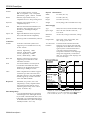
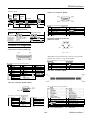
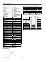
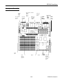
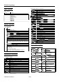
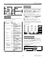
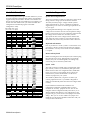
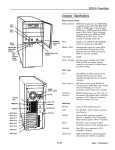
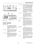
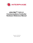
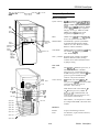
EPSON PowerSpan
(This desc~ihes the updated Powe~Span with the wd logo on the
Computer Specifications
front.,
Main System Board
System memory
SME RAM standard on two 4ME SIMMs;
expandable using lMB, 2MB, 4ME, SME,
16ME, or 32ME single- or double-sided
SIMMs up to 128ME (maximum); SIMMs
must be Sons, 36-bit, 72-pin, tin-plated,
fast-page mode type; 16ME and 32ME
SIMMs may be 7Ons, 36-bit, 72-pin,
tin-plated, fast-page mode type
BIOS
256KE on two 128KE FLASH EEPROM
devices for system and video BIOS
Shadow RAM
Automatically copies the system BIOS
from ROM into RAM; shadow RAM
addresses for video BIOS and external
BIOS are software selectable
Video RAM
512KE standard; expandable to 1ME using
four 256KE x 4,60ns, fast-page mode
video DRAM chips
Clock / calendar
Real-time clock, calendar, and CMOS
RAM for BIOS use; battery backup;
contents can be cleared to default values
by jumper setting
reset
button
\
power
button \
keyboard/
mouse lock
button
power
indicator ,
IDE/SCSI hard
disk drive
activity
indicator
r
keyboard/mouse lock
indicator
CPU Card
voltage
selector switch
CPU
Intel 486DX2,66 MHz microprocessor; or
Intel Pentium 60 MHz or 90 MHz
microprocessor; or Intel Dual Pentium
66 MHz microprocessor; simulated 8 MHz
processor speed selectable through
software or keyboard command
Cache memory
SKE internal cache in the 486DX2 / 66
microprocessor; 128KE Intel cache module
with write-through, two-way set
associative cache memory
AC inlet
keyboard
16KE internal cache in the Pentium / 60
and / 90 microprocessors; 256KE
(Pentium/60) or 512KE (Pentium/ 90)
cache module with write-back, two-way
set associative cache memory
Port
mouse port
serial port 2
serial port 1
parallel port
VGA port
ttIvY
B
01
option slot 1
Dual Pentium / 66 microprocessor contains
two independent 256KB, write-back cache
modules
cover lock
option slot 2
option slot 3
option slot 4
Interfaces
option slot 5
Monitor
15-pin, D-shell analog connector
Serial
Two RS-232-C, 9-pin, D-shell connectors;
asynchronous
option slot 6
option slot 7
option slot 8
’
10/94
EPSON PowerSpan-1
EPSON PowerSpan
Parallel
25-pin, D-shell connector; supports
IBM AT compatible or PS/ 2 compatible
(bidirectional) signals; software selectable
Physical Characteristics
Width
8.5 inches (21.5 cm)
Mini DIN, 6-pin connector for PS / 2
compatible mouse or other pointing device
Depth
23 inches (58.4 cm)
Height
20.4 inches (51.8 cm)
Keyboard
Mini DIN, 6-pin connector for PS / 2
compatible keyboard
Weight
44.5 lb (20 kg) with one diskette drive only
SCSI
Built-in TwinChannel SCSI interface; two
SCSI buses, each supporting up to seven
SCSI devices, including the adapter
(interface)
Mouse
Option slots
Eight 32-bit EISA bus master expansion
slots (16-bit and S-bit ISA compatible)
Speaker
Internal; operation controllable by software
Power Supply
Type
230W, fan-cooled, switch-selectable voltage
Input ranges
100 to 120 VAC and 200 to 240 VAC,
50 to 60 Hz
Maximum
current
At 115 Volts, 5 Amps; at 230 Volts, 4 Amps
Output cables
Three main system board cables; nine
mass storage power cables
+5 Volt current
limitation
To determine the maximum allowable
amperage of your option cards and other
equipment, use the table below. It lists the
typical system +5 Volt current drain for
your main system board and other
components. Check the +5 Volt amperage
rating of the equipment you install and
make sure the total system amperage does
not exceed 30 Amps..
Controllers
Diskette
Controller on the main system board
supports up to two diskette drives in any
of these formats:
5.25-inch,
5.25-inch,
3.5-inch,
3.5-inch,
Hard disk
SCSI
Video
Keyboard
high-density, 1.2MB
double-density, 360KB
high-density, 1.44MB
double-density, 720KB
Interface on the main system board
supports up to two IDE drives with
embedded controllers
S,ystem cumnt drain
Two SCSI-2 interfaces on main system
board feature 32-bit EISA bus master
interface; Twin Channel SCSI supports
transfers up to 10MB per second
Main system board
Total installed memory
on SlMMs
VESA compliant VGA controller supports
resolutions up to 800 x 600 in 256 colors
and 1024 x 768 in 16 colors with 512KB of
VRAM; supports up to 1024 x 768 in 256
colors with 1MB of VRAM
CPU cards:
486DX2/66 lw 128KB
cache
Pentium 60
Pentium 66
Pentium 90
Dual Pentium 66
CPU card integrated
cache (128KB)
3.5inch diskette drive
EISA option slot *
Cooling fan
Detachable, two position, 101 or 102
sculpted keys; country-dependent main
typewriter keyboard; numeric/cursor
control keypad; four-key cursor control
keypad; 12 function keys
*
Mass Storage Bays
Up to nine half-height devices maximum;
one full-height or two half-height internal
bays for IDE or SCSI hard disk drives; four
half-height or two full-height internal bays
for SCSI hard disk drives; three half-height
externally-accessible drive bays
EPSON PowerSpan-2
10/94
+5v
amperage
(typical)
4.OA
4MB
2.OA
8MB
2.1A
6 4 M B 2.4A
128MB 2.8A
T
+12v
amperage
-12v
amperage
.06A
-
-
4.1A
5.4A
5.8A
1.2A
11.9A
2.5A
0.5A
2.OA
-
0.3A
Each EISA option slot is rated at 4.5A per slot, however average current
consumption for all slots used should not exceed 3A per slot. Most EISA
option cards draw 2A. If you install a card drawing more than 2A, install it in
a lower numbered slot (such as 1 or 2) to ensure adequate cooling.
EPSON PowerSpan
Maximum outputs
Output
voltage
PC)
+5
-5
+12
-12
Serial Port Connectors (J0700)
Maximum
continuous
current
(Amps)
30A
0.5A
8A
O.lA
T
Minimum
load
3A
0A
0.25A
0A
Peak surge
30A
0.5A
IIA
Maximum capacitive
load ~350 F
Watts
15ow
2.5W
96W
12w
Swial port connector pin assignnw0zts
Pin
1
2
3
4
Environmental Requirements
Condition
Temoerature
Operating
range
5O’to 95’ F
Non-operating range
40’ to 149’ F
(4O’to 65’ C)
20% to 92% at 149’ F
(65’ C)
To 50.000 ft (15.240 m)
Signal
Data Carrier Detect
Receive Data
Transmit Data
Data Terminal Ready
Pin
6
7
9
Keyboard and Mouse Connector
(JO800 two-tiered)
Pin
6
Connector Pin Assignments
Pin
Pin 14
Pin
1
Keyhoayd and mouse connector pin assignmL&s
PaYallel port connector pin assignments
1 Pin 1 Signal
IO
ACK*
11
BUSY
12
PE
13
SELECT
14
AUTO*
1 15 1 ERROR*
2
Although the keyboard and mouse connectors are physically
identical, they cannot be used interchangeably.
(y-1
1 Pin 1 Signal
1
STROBE
2
DATA0
3
DATA1
4
DATA2
5
DATA3
16 1 DATA4
DATA5
DATA6
DATA7
5
Pin 4 43 Pin 3
Pin 1
Pin 25
Pin
I
Parallel Port Connector (JO600 top)
Pin 13
Signal
Data Set Ready
Rearrest To Send
Clear To Send
Ring Indicator
1 Pin 1 Signal
19
SIGNAL GND
20
SIGNAL GND
21
SIGNAL GND
22
SIGNAL GND
23
SIGNAL GND
124
1 SIGNALGND
SIGNAL GND
Pin
1
2
3
I
Signal
Data
NC
Ground
Pin
4
5
6
Signal
+5 VDC (fused)
Clock
NC
CPU Card Connector (J0730)
1
Pin 131
Pin 1
*Active low logic
Pin 2
Pin 132
VGA Port Connector (JO600 bottom)
CPU cayd connector pin assignments
~~
VGA port connector pin assignmL&s
Pin
1
2
3
4
5
Signal
Red
Green
Blue
NC
Ground
8
1 Ground
Pin
11
12
13
14
15
13
15
17
19
21
Horizontal Sync
Vertical Sync
10/94
Cache Flush
Write Modified Cache Entries
Maskable Interrupt
+5 VDC
1Snoop Status Available
14
16
18
20
122
Ground
Interrupt Request 13
Nonmaskable Interrupt
Cache Data Modified
1Snoop Strobe
EPSON PowerSpan-3
EPSON PowerSpan
CPU card connector pin assignments (continued)
CPU cayd
po71w
Pin Signal
1
Ground
2
+5 VDC
CPU cayd
po71w
Pin Signal
1
Ground
2
vcc
and ground connector TO71 0 pin assignments
Pin Signal
3
Ground
4
+5 VDC
Pin Signal
5
Ground
6
+5 VDC
and ground connector TO770 pin assignments
Pin Signal
3
Reserved
4
Reserved
Pin Signal
5
Reserved
6
vcc
SCSI Channel A and B Connectors (J0060 and J0080)
SCSI channel A and B connector pin assignmL&s
51
53
55
57
59
61
63
65
67
69
71
73
75
77
79
81
83
85
87
89
91
93
95
97
99
1101
103
105
107
109
Ill
113
115
117
119
121
123
125
127
129
131
Address Bit
Address Bit
+5 VDC
Address Bit
Address Bit
1Address Bit
1Address Bit
+5 VDC
Address Bit
Address Bit
Ground
Address Bit
Address Bit
Address Bit
+5 VDC
Address Bit
Address Bit
Ground
Address Bit
Address Bit
Ground
Data Bit 1
Ground
Data Bit 3
Data Bit 5
1Data Bit 7
Data Bit 9
Data Bit 11
Ground
Data Bit 13
Data Bit 15
1Data Bit 17
Data Bit 19
Data Bit 21
Ground
Data Bit 23
Data Bit 25
1Data Bit 27
1Data Bit 29
1Data Bit 31
1Ground
3
5
52
54
56
58
60
162
164
66
68
70
72
74
76
78
80
82
84
86
88
90
92
94
96
98
100
1102
104
106
108
110
112
1114
116
118
120
122
124
1126
1128
1130
132
7
9
11
13
15
17
19
21
23
25
27
29
31
Byte Enable 2
+5 VDC
Address Bit 2
Address Bit 4
Address Bit 6
1Ground
1Address Bit 8
Address Bit IO
+5 VDC
Address Bit 12
Address Bit 14
Address Bit 16
Address Bit 18
+5 VDC
Address Bit 20
Address Bit 22
Address Bit 24
Address Bit 26
Ground
Address Bit 28
Address Bit 30
Ground
Data Bit 0
Data Bit 2
Data Bit 4
1 +5VDC
Data Bit 6
Data Bit 8
Data Bit IO
Data Bit 12
Data Bit 14
1 +5VDC
Data Bit 16
Data Bit 18
Data Bit 20
Data Bit 22
Data Bit 24
1+5VDC
1Data Bit 26
1Data Bit 28
1Data Bit 30
1
~Pin
S i g n a l
:
3
9
IO
11
12
13
14
15
16
I
I
CPU Card Power and Ground Connectors
(J0710 and J0770)
Pin 1
Pin 5
Pin 2
EPSON PowerSpan-4
10/94
1 Ground
Ground
Ground
Ground
Reserved
Open
Reserved
Ground
Ground
20
21
22
23
24
25
26
27
-DB2
-DB3
-DB4
-DB5
-DB6
Reserved
Termpwr
Reserved
Ground
-ATN
Ground
-BSY
-ACK
-RST
-MSG
-SEL
-CID
-REQ
EPSON PowerSpan
Main System Board Map
video memory socketss
U0830
U0732
U0731
U0730
jumpers
E0722
E0721
E0720
CPU card
connector
J0710
CPU card
connector
J0770
SIMM sockets
IDE hard
disk drive
interface
option
slots
VGA
feature
connector
(JO41 0)
SCSI A
10/94
SCSI B
SCSI hard
disk drive
activity LED
connector
JO190
EPSON PowerSpan-5
EPSON PowerSpan
DMA Channels
DMA channels
1 Function
1Option card
Channel
0
System Interrupts
System
IRQ
NMI
0
1
2
3
4
5
6
7
8
9
IO
11
12
13
14
15
intmupts
Device
Parity error
Reserved, interval timer
Reserved, keyboard buffer full
Reserved, cascade interrupt from slave PIC
Onboard serial pod 2 (COM2), if enabled
Onboard serial pod 1 (COMI), if enabled
LPT2, if enabled
Onboard diskette drive controller, if enabled
LPTI, if enabled
Real-time clock (RTC)
User definable; can be set for EISA option cards using the ECU
COM3, if enabled; can be set for EISA option cards using the ECU
COM4, if enabled; can be set for EISA option cards using the ECU
SCSI controller, if enabled; can be set for EISA option cards using the
ECU
Onboard PS12 mouse pod, if enabled
Reserved, math coprocessor
IDE hard drive controller, if enabled
User definable; can be set for the following (up to three choices)
using the ECU:
EISA option cards
IDE hard disk drive controller
Built-in video controller; programmable to 9, 10, II, or 15
Built-in SCSI controller; programmable to 9, 10, II, or 15
Input/output addresses (continued)
l/O address
OAO - OAI
OCO - ODE
OF0
OF8 - OFF
IFO- IF8
278 - 278
12C0 - 2DF
2E8 - 2EF
2F8 - 2FF
378 - 37F
380 - 388
3BC - 3BE
3BF - 3DF
3E8 - 3EF
3F0 - 3F5
3F6
3F7
3F7
3F8 - 3FF
400 - 408
40C - 40F
461 - 464
464 - 465
480 - 48F
4C2 - 4CE
4D0
4Dl
4D4
4D4
co2 - co4
C80 - C83
C84
C85 - C87
9nnn - 9FFF
System Memory Map
Starting
address
IKB
512KB
Input/output Addresses
540KB
Input/output addresses
l/O address
000 - 00F
020 - 021
026
027
040 - 043
048 - 048
060,064
061
070
070
071
078
080
081 - 08F
768KB
Device
Slave DMA controller 1
Master interrupt controller 1
Configuration controller index registers
Configuration controller data registers
Interval timer 1
Interval timer 2
Keyboard/mouse controller
NMI and diagnostic pod
Real-time clock
Enable NMI
Real-time clock
BIOS loop timer
Power-on diagnostic error codes
DMA page register
EPSON PowerSpan-6
Device
Slave interrupt controller 2
Master DMA controller 2
Reset numeric coprocessor
Numeric coprocessor
IDE hard drive controller
Parallel pod 2 (LPT2); parallel port 3 (PS/2-compatible)
Clock calendar
Serial port 4 (COM4)
Serial port 2 (COM2)
Parallel pod 1 (LPTI); parallel port 2 (PS/2-compatible)
WD9OC31 onboard video registers
Parallel pod 3 (LPTB); parallel port 1 (PS/2-compatible)
16C552 registers
Serial port 3 (COM3)
Onboard diskette controller
Onboard IDE hard drive controller
Onboard IDE read
Onboard diskette controller read/write
Serial port 1 (COMI)
Extended DMA controller 1 registers
Extended control/test registers
Extended NMI register
Extended bus master
Extended DMA page register
Extended DMA 2 registers
Extended interrupt 1
Extended interrupt 2
Extended DMA 2 chaining
Extended DMA 2 write mode
System baseboard configuration information
Svstem baseboard EISA ID resister
System baseboard enable
Reserved
Built-in SCSI controller
300KB
332KB
896KB
928KB
936KB
944KB
10/94
iex address
.ange
IOOOOh to
17FFFh
30000h to
3FFFFh
Size
512KB
Function
3ase memory
128KB
3ase memory enabled in
SETUP or the EISA
Zonfiguration utility
dideo display RAM
IAOOOOh to
IBFFFFh
ICOOOOh to
lC7FFFh
128KB
lC8000h to
3FFFFh
IDOOOOh to
JFFFFh
OEOOOOh to
OE7FFFh
32KB
OE8000h to
E9FFFh
OEAOOOh to
OEBFFFh
OECOOOh to
OEFFFFh
32KB
54KB
32KB
Dffboard video BIOS (can be
shadowed) or built-in SCSI
310s (can be shadowed)
Adapter BIOS extensions (can
oe shadowed)
Adapter BIOS extensions
Built-in video BIOS (can be
shadowed or mapped to
OCOOOOh)
EISA Configuration utility data
Reserved memory
16KB
Recovery BIOS
EPSON PowerSpan
System memory map (continued)
Starting
address
960KB
FFFFFh
1 OOOOOh to
FFFFFFFh
OCSOOOh to
ODFFFFh
1MB
Top of
system
memory
Top of
system
SIMM Installation
Hex address
t
Oh to SOOFFFFFh
Size
64KB
Function
System BIOS
15MB
Extended memory
96KB
Reserved for ROM and RAM
expansion boards
2GB +
1MB
Limit of system architecture
There are four SIMM sockets organized in two banks on the
main system board. You can install 36-bit, tin-plated, fastpage mode, single or double-sided SIMMs with a capacity of
lMB, 2MB, 4MB, or SME running at 7Ons or a capacity of
16ME or 32ME running at 70ns or 801~. Check the following
guidelines to ensure that you choose the correct type of
SIMMs and install them properly:
u Use only 36-bit, tin-plated, fast-page mode, single- or
double-sided SIMMs that operate at an access speed of 70
or 80 nanoseconds (ns). You can install lME, 2ME, 4ME,
or SME Sons SIMMs and 16ME or 32ME 7Ons SIMMs.
t?Et?lOlV
Jumper Settings
u Fill each bank with two SIMMs of the same size.
See the Main System Board Map on page 5 for the location of
the jumpers on the main system board.
Main system board jumper settings
u Install SIMMs in Bank 0 first (sockets JO550 and J0551).
Then use Bank 1 (sockets JO650 and J0651).
The table below lists some sample memory configurations.
You can install SIMMs in many different configurations than
those listed in the table.
Enables FLASH memory BIOS for
SIMM configurations
T Total
Disables onboard video controller so
you can install a video controller on
t
It
(read/write mode) for any diskette
drive connected to the built-in
t
t
t
Enables write-protection (read-only
mode) for any diskette drive
32 MB
32 MB
Changes EISA configuration or
SETUP values stored in non-volatile
132MB
132MB
116MB
132MB
116MB
132MB
memory
8 MB*
IOMB
16MB
16MB
24 MB
32 MB
32 MB
64 MB
96 MB
128 MB
*Standard memory configuration
Disables and clears the power-on
Video Memory Installation
installed in Bank 0
16MB or 32MB SlMMs are installed
The computer comes with 512KE of video memory that you
can increase to 1MB by installing four video DRAM DIP
chips. The chips must be 20-pin, 256KE, fast-page mode chips
that operate at 60ns access speed. You must install one chip
in each empty video RAM socket.
installed in Bank 1
16MB or 32MB SlMMs are installed
The table bellow lists the video DRAM DIP chips that are
approved for use in the computer.
Video DRAM DIP chip types
using the EISA Configuration utility or
Manufacturer
Hyundai
address to 03C3H if you installed a
Fuiitsu
Starting video controller address is
Samsung
Part number
HY534256AS-60
HY534256ALS-60
MB8’lC4256A-60P
1V53C104FP-60
1KM44C256CP-6
L
* Default setting
10/94
EPSON PowerSpan-7
EPSON PowerSpan
Hard Disk Drive Types
Installation/Support Tips
The following table lists the types of hard disk drives you can
use in the computer. Check this table and the documentation
supplied with your hard disk to find the correct number for
the type of hard disk drive(s) installed in your computer. You
need to enter this number when you set the hard disk drive
configuration in the SETUP program or the EISA
Configuration utility.
System Power Requirements
06
07
08
09
10
11
12
1820
918
762
900
977
1855
1855
110
15
8
15
5
15
17
1-1
-1
0
-1
0
1-1
1-1
117
17
39
17
17
117
117
168MB
114MB
116MB
112MB
40MB
135MB
149MB
The power cord must be rated for at least 125% of the current
rating of the AC voltage system and must be less than
14.76 feet (4.5 meters) long to comply with the system’s
safety requirements. Do not use or attempt to modify the
supplied AC power cord if it is not the type required for use
in your region.
To avoid permanent damage to the computer, be sure the
voltage selector switch is set to the correct input line voltage
before you turn on the power. The computer is shipped with
the voltage selector switch set to 115 VAC, which is
appropriate for line source voltages between 100 and 120
VAC. If the line source voltage in your location is between
200 and 240 VAC, make sure you set the switch to 230 VAC.
I
Keyboard and Monitor
Even if you intend to use this system as a network file server,
you need to connect a monitor and a keyboard to complete
the installation. You may remove them once the installation
is complete.
Mouse and Keyboard
120
21
22
23
24
25
1814
968
873
636
830
751
19
10
13
16
10
8
1-1
-1
-1
-1
-1
-1
132
34
36
63
26
17
1114MB
160MB
199MB
313MB
105MB
49MB
I
When connecting the mouse and keyboard, be careful to plug
them into the proper ports. Although they are physically
identical, they are not interchangeable, and damage may
occur to the ports or the main system board.
Option Cards
The order in which you install option cards depends on the
type of cards you have. If you install only ISA option cards
that do not have their own configuration files, install them
before you connect your peripheral devices. Follow the
instructions in your ISA card manual to set the card’s
switches or jumpers for your system.
Also install any EISA cards you plan to use before you
connect peripheral devices so your EISA Configuration
utility can automatically detect the cards and configure them
correctly.
40
41
42
43
44
45
615
917
1023
820
I-
8
15
15
6
I-
128
-1
-1
-1
I-
17
17
17
17
I-
46
47
48,49
925
699
-
9
7
-
-1
256
-
17
17
-
EPSON PowerSpan-8
40MB
114MB
127MB
Unused
40MB
I Unused
69MB
40MB
User-definable
If you install ISA cards that came with their own
configuration (CFG) files, install them after you have
connected the necessary peripheral devices and run the
computer’s EISA Configuration utility. This allows you to
add the CFG file information to your configuration so the
program can give you the card’s correct jumper and switch
settings. Then you can set the switches and jumpers and
install the card. See the documentation that came with your
card(s) for more information.
I
10/94
EPSON PowerSpan
SETUP Program
Use the SETUP program in your system’s BIOS ROM to
configure your computer only if you installed only ISA
option cards that did not come with CFG files or you do not
have a diskette drive or you have disabled the diskette drive.
Run the EISA Configuration utility to configure the system in
all other cases.
Information Reference List
Engineering Change Notices
None.
Technical Information Bulletins
None.
Product Support Bulletins
None.
Related Documentation
TM-PSPAN
EPSON PowerSpan Service Manual
PL-PSPAN
EPSON PowerSpan Parts Price List
400363600
EPSON PowerSpan User’s Guide
10/94
EPSON PowerSpan-9